Experimental Setup: Two Camera Four-Exposure PIV · PDF fileExperimental Setup: Two Camera...
8
Experimental Setup: Two Camera Four-Exposure PIV • Dimensions of Cavity Cavity width (L): 38.1mm Cavity depth (H): 30.0mm • Laser New Wave minilase Nd:YAG Laser, 10-15mJ/pulse. • Cameras Kodak ES4.0 -8bit 2Kx2K; Photron FASTCAN-ultima APX (high-speed ); Kodak Ektapro 1012 (high-speed ). • Lens Nikon 105mm f/2.8D AF • Tracer Particles Hollow glass spheres, 8-12m, specific gravity 1.05-1.15. • Free Stream Speed in Experiment 5 m/s – 10 m/s. Flow Direction Leading Edge Trailing Edge Cavity Wall L=38.1 mm H=30.0 mm
Transcript of Experimental Setup: Two Camera Four-Exposure PIV · PDF fileExperimental Setup: Two Camera...

Experimental Setup: Two Camera Four-Exposure PIV• Dimensions of Cavity
Cavity width (L): 38.1mm Cavity depth (H): 30.0mm
• Laser
New Wave minilase Nd:YAG Laser, 10-15mJ/pulse.
• Cameras
Kodak ES4.0 -8bit 2Kx2K;
Photron FASTCAN-ultima APX (high-speed);
Kodak Ektapro 1012 (high-speed).
• Lens
Nikon 105mm f/2.8D AF
• Tracer Particles
Hollow glass spheres, 8-12m, specific gravity 1.05-1.15.
• Free Stream Speed in Experiment
5 m/s – 10 m/s.
Flow DirectionLeading Edge Trailing Edge
Cavity Wall
L=38.1 mm
H=30.0 mm
Presenter
Presentation Notes
Now let’s look at the experimental setup. This is the cavity model installed in a water tunnel. The width of the cavity is 38.1mm. The measurement system consists of two sets of lasers and two CCD cameras. The two sets of laser beams are orthogonally polarized so that the cameras receive only the designated scatter light. Now let’s move on to the next part: experimental results. In addition to the spatial pressure measurement, we also used high-speed cameras to record images of the cavitation inception.

• High Speed Camera– PCO.dimax, 12 bit– Resolution: 1008x1000 pixels @ 4500 fps– Resolution: 2000x2000 pixels @ 1400 fps
• High Repetition Rate Laser– Photonics DM60-527 Nd:YLF– Maximum pulse rate - 10 kHz– Pulse energy: 60mJ at 1KHz
• Tracer Particles
-- Hollow glass spheres, 8-12m• Dimensions of Cavity
– Cavity width (L): 38.1mm– Cavity depth (H): 30.0mm
• Free Stream Speed in Experiment– 1.125m/s
• Reynolds Number– Re=37,700 (based on cavity width)
• Image size: 25x25 mm
• Vector Spacing: 0.2 mm
• Interrogation window size: 0.4X0.4 mm
Flow Direction
Leading Edge Trailing Edge
Cavity Wall
L=38.1 mm
H=30.0 mm
Field of View (2525 mm)
Experimental Setup: Time-Resolved Measurements with High-Speed Camera
Presenter
Presentation Notes
The camera sampling frequency is 4500 frames per second. The Reynolds number is 37,000. We performed the measurements at this highlighted region around the cavity corner.
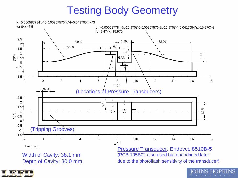
Testing Body Geometry
Pressure Transducer: Endevco 8510B-5(PCB 105B02 also used but abandoned laterdue to the photoflash sensitivity of the transducer)
Width of Cavity: 38.1 mmDepth of Cavity: 30.0 mm
y= -0.000587784*(x-15.970)^5-0.00957576*(x-15.970)^4-0.0417054*(x-15.970)^3for 9.47<x<15.970
y= 0.000587784*x^5-0.00957576*x^4+0.0417054*x^3for 0<x<6.5
(Locations of Pressure Transducers)
(Tripping Grooves)
-1.5-1
-0.50
0.51
1.52
2.5
-2 0 2 4 6 8 10 12 14 16 18x (in)
-1.5-1
-0.50
0.51
1.52
2.5
-2 0 2 4 6 8 10 12 14 16 18x (in)
6.500
Unit: inch
8.000 1.500 6.5000.4
0.75
0.52

Testing Body Picture
Presenter
Presentation Notes
Now this picture shows what the testing body looks like when we first got it from the machine shop. The opening for the installation of flush-mounted pressure transducer can be clearly seen. This tiny-tiny hole is the pressure tap for monitoring the static pressure upstream of the cavity.

Water Tunnel Test Section
Presenter
Presentation Notes
Now I’d like to show you what the facility looks like. This is the test-section of the water-tunnel. These are the optics for the laser beams, and these two black boxes are power supplies for the Nd:Yag lasers.

Two-Camera Four-Exposure Setup
Presenter
Presentation Notes
Now the close-up view of the two identical Kodak ES4.0 CCD cameras. In front of the lens is the 2 inch polarizing beam splitter cube.

Two Double Head Laser
Presenter
Presentation Notes
This picture shows the close-up view of the optics for combining the two laser beams. A half-wave plate is used to turn the polarization direction of this laser beam to be perpendicular to the other.

High Speed Camera
high speed camera
test section
2D cavity model