EXPERIMENTAL INVESTIGATION OF THE SHEAR CAPACITY … · EXPERIMENTAL INVESTIGATION OF THE SHEAR...
6
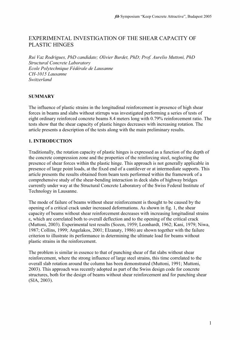
fib Symposium “Keep Concrete Attractive”, Budapest 2005 1 EXPERIMENTAL INVESTIGATION OF THE SHEAR CAPACITY OF PLASTIC HINGES Rui Vaz Rodrigues, PhD candidate; Olivier Burdet, PhD; Prof. Aurelio Muttoni, PhD Structural Concrete Laboratory Ecole Polytechnique Fédérale de Lausanne CH-1015 Lausanne Switzerland SUMMARY The influence of plastic strains in the longitudinal reinforcement in presence of high shear forces in beams and slabs without stirrups was investigated performing a series of tests of eight ordinary reinforced concrete beams 8.4 meters long with 0.79% reinforcement ratio. The tests show that the shear capacity of plastic hinges decreases with increasing rotation. The article presents a description of the tests along with the main preliminary results. 1. INTRODUCTION Traditionally, the rotation capacity of plastic hinges is expressed as a function of the depth of the concrete compression zone and the properties of the reinforcing steel, neglecting the presence of shear forces within the plastic hinge. This approach is not generally applicable in presence of large point loads, at the fixed end of a cantilever or at intermediate supports. This article presents the results obtained from beam tests performed within the framework of a comprehensive study of the shear-bending interaction in deck slabs of highway bridges currently under way at the Structural Concrete Laboratory of the Swiss Federal Institute of Technology in Lausanne. The mode of failure of beams without shear reinforcement is thought to be caused by the opening of a critical crack under increased deformations. As shown in fig. 1, the shear capacity of beams without shear reinforcement decreases with increasing longitudinal strains ε, which are correlated both to overall deflection and to the opening of the critical crack (Muttoni, 2003). Experimental test results (Sozen, 1959; Leonhardt, 1962; Kani, 1979; Niwa, 1987; Collins, 1999; Angelakos, 2001; Elzanaty, 1986) are shown together with the failure criterion to illustrate its performance in determining the ultimate load for beams without plastic strains in the reinforcement. The problem is similar in essence to that of punching shear of flat slabs without shear reinforcement, where the strong influence of large steel strains, this time correlated to the overall slab rotation around the column has been demonstrated (Muttoni, 1991; Muttoni, 2003). This approach was recently adopted as part of the Swiss design code for concrete structures, both for the design of beams without shear reinforcement and for punching shear (SIA, 2003).
Transcript of EXPERIMENTAL INVESTIGATION OF THE SHEAR CAPACITY … · EXPERIMENTAL INVESTIGATION OF THE SHEAR...
fib Symposium “Keep Concrete Attractive”, Budapest 2005
1
EXPERIMENTAL INVESTIGATION OF THE SHEAR CAPACITY OF PLASTIC HINGES Rui Vaz Rodrigues, PhD candidate; Olivier Burdet, PhD; Prof. Aurelio Muttoni, PhD Structural Concrete Laboratory Ecole Polytechnique Fédérale de Lausanne CH-1015 Lausanne Switzerland SUMMARY The influence of plastic strains in the longitudinal reinforcement in presence of high shear forces in beams and slabs without stirrups was investigated performing a series of tests of eight ordinary reinforced concrete beams 8.4 meters long with 0.79% reinforcement ratio. The tests show that the shear capacity of plastic hinges decreases with increasing rotation. The article presents a description of the tests along with the main preliminary results. 1. INTRODUCTION Traditionally, the rotation capacity of plastic hinges is expressed as a function of the depth of the concrete compression zone and the properties of the reinforcing steel, neglecting the presence of shear forces within the plastic hinge. This approach is not generally applicable in presence of large point loads, at the fixed end of a cantilever or at intermediate supports. This article presents the results obtained from beam tests performed within the framework of a comprehensive study of the shear-bending interaction in deck slabs of highway bridges currently under way at the Structural Concrete Laboratory of the Swiss Federal Institute of Technology in Lausanne. The mode of failure of beams without shear reinforcement is thought to be caused by the opening of a critical crack under increased deformations. As shown in fig. 1, the shear capacity of beams without shear reinforcement decreases with increasing longitudinal strains ε, which are correlated both to overall deflection and to the opening of the critical crack (Muttoni, 2003). Experimental test results (Sozen, 1959; Leonhardt, 1962; Kani, 1979; Niwa, 1987; Collins, 1999; Angelakos, 2001; Elzanaty, 1986) are shown together with the failure criterion to illustrate its performance in determining the ultimate load for beams without plastic strains in the reinforcement. The problem is similar in essence to that of punching shear of flat slabs without shear reinforcement, where the strong influence of large steel strains, this time correlated to the overall slab rotation around the column has been demonstrated (Muttoni, 1991; Muttoni, 2003). This approach was recently adopted as part of the Swiss design code for concrete structures, both for the design of beams without shear reinforcement and for punching shear (SIA, 2003).
2
0.00
0.05
0.10
0.15
0.20
0.25
0.30
0.35
0.40
0.0 0.2 0.4 0.6 0.8 1.0 1.2 1.4 1.6 1.8 2.0 2.2
[mm]
b dVRτR =
1648
max +⋅⋅
Ddε
16487.73
1
max +⋅⋅⋅+
=⋅⋅
Ddfdb
V
c
R
εc
R
fdbV⋅⋅
0.0
0.1
0.2
0.3
0.4
0.5
0.6
0.7
0.8
0 1 2 3 4 5 6 7 8 9 10 11
[mm]
θ
1648
max +⋅⋅
Ddθ
164831.01
75.0
max +⋅⋅⋅+
=⋅⋅
Ddfdu
V
c
R
θc
R
fduV⋅⋅
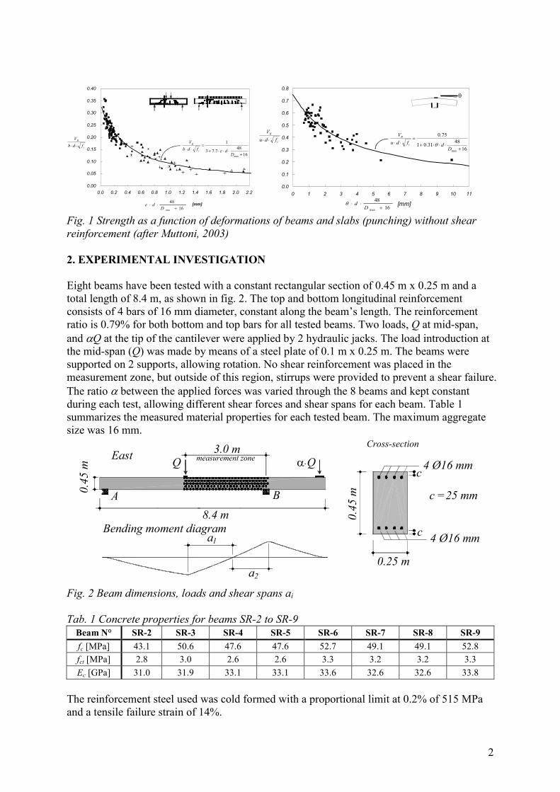
Fig. 1 Strength as a function of deformations of beams and slabs (punching) without shear reinforcement (after Muttoni, 2003) 2. EXPERIMENTAL INVESTIGATION Eight beams have been tested with a constant rectangular section of 0.45 m x 0.25 m and a total length of 8.4 m, as shown in fig. 2. The top and bottom longitudinal reinforcement consists of 4 bars of 16 mm diameter, constant along the beam’s length. The reinforcement ratio is 0.79% for both bottom and top bars for all tested beams. Two loads, Q at mid-span, and αQ at the tip of the cantilever were applied by 2 hydraulic jacks. The load introduction at the mid-span (Q) was made by means of a steel plate of 0.1 m x 0.25 m. The beams were supported on 2 supports, allowing rotation. No shear reinforcement was placed in the measurement zone, but outside of this region, stirrups were provided to prevent a shear failure. The ratio α between the applied forces was varied through the 8 beams and kept constant during each test, allowing different shear forces and shear spans for each beam. Table 1 summarizes the measured material properties for each tested beam. The maximum aggregate size was 16 mm.
4 Ø16 mm
A B8.4 m
Q α⋅Q
0.45
m
0.45
m
0.25 m
c
c
c =25 mm
4 Ø16 mm
East
aBending moment diagram
Cross-section
1
a2
3.0 mmeasurement zone
Fig. 2 Beam dimensions, loads and shear spans ai Tab. 1 Concrete properties for beams SR-2 to SR-9
Beam N° SR-2 SR-3 SR-4 SR-5 SR-6 SR-7 SR-8 SR-9 fc [MPa] 43.1 50.6 47.6 47.6 52.7 49.1 49.1 52.8 fct [MPa] 2.8 3.0 2.6 2.6 3.3 3.2 3.2 3.3 Ec [GPa] 31.0 31.9 33.1 33.1 33.6 32.6 32.6 33.8
The reinforcement steel used was cold formed with a proportional limit at 0.2% of 515 MPa and a tensile failure strain of 14%.
3
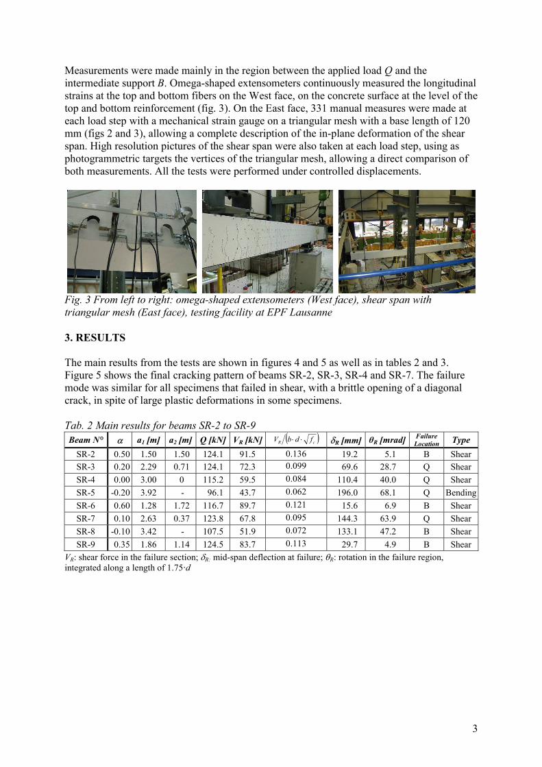
Measurements were made mainly in the region between the applied load Q and the intermediate support B. Omega-shaped extensometers continuously measured the longitudinal strains at the top and bottom fibers on the West face, on the concrete surface at the level of the top and bottom reinforcement (fig. 3). On the East face, 331 manual measures were made at each load step with a mechanical strain gauge on a triangular mesh with a base length of 120 mm (figs 2 and 3), allowing a complete description of the in-plane deformation of the shear span. High resolution pictures of the shear span were also taken at each load step, using as photogrammetric targets the vertices of the triangular mesh, allowing a direct comparison of both measurements. All the tests were performed under controlled displacements.
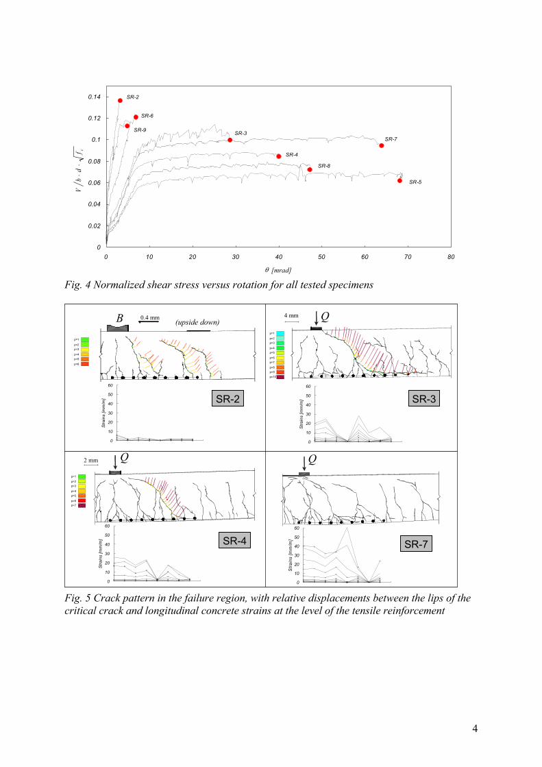
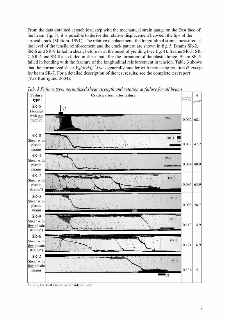
Fig. 3 From left to right: omega-shaped extensometers (West face), shear span with triangular mesh (East face), testing facility at EPF Lausanne 3. RESULTS The main results from the tests are shown in figures 4 and 5 as well as in tables 2 and 3. Figure 5 shows the final cracking pattern of beams SR-2, SR-3, SR-4 and SR-7. The failure mode was similar for all specimens that failed in shear, with a brittle opening of a diagonal crack, in spite of large plastic deformations in some specimens. Tab. 2 Main results for beams SR-2 to SR-9 Beam N° α a1 [m] a2 [m] Q [kN] VR [kN] ( )cR fdbV ⋅⋅ δR [mm] θR [mrad] Failure
Location Type
SR-2 0.50 1.50 1.50 124.1 91.5 0.136 19.2 5.1 B Shear SR-3 0.20 2.29 0.71 124.1 72.3 0.099 69.6 28.7 Q Shear SR-4 0.00 3.00 0 115.2 59.5 0.084 110.4 40.0 Q Shear SR-5 -0.20 3.92 - 96.1 43.7 0.062 196.0 68.1 Q BendingSR-6 0.60 1.28 1.72 116.7 89.7 0.121 15.6 6.9 B Shear SR-7 0.10 2.63 0.37 123.8 67.8 0.095 144.3 63.9 Q Shear SR-8 -0.10 3.42 - 107.5 51.9 0.072 133.1 47.2 B Shear SR-9 0.35 1.86 1.14 124.5 83.7 0.113 29.7 4.9 B Shear
VR: shear force in the failure section; δR: mid-span deflection at failure; θR: rotation in the failure region, integrated along a length of 1.75·d
4
cR fτ
0
0.02
0.04
0.06
0.08
0.1
0.12
0.14
0 10 20 30 40 50 60 70 80
θ [mrad]
SR-2
SR-3
SR-4
SR-5
SR-6
SR-7
SR-8
SR-9
cfd
bV
⋅⋅
Fig. 4 Normalized shear stress versus rotation for all tested specimens
SR-2
0
10
20
30
40
50
60
Stra
ins
[mm
/m] SR-3
p=6
p=5p=4
p=3p=2
p=1
p=8
p=7
p=9p=10
4 mm Q
0
10
20
30
40
50
60
Stra
ins
[mm
/m]
SR-4
p=6
p=5p=4
p=3p=2
p=1
p=7
2 mm Q
0
10
20
30
40
50
60
Stra
ins
[mm
/m]
Q
0
10
20
30
40
50
60
Stra
ins
[mm
/m]
SR-7
p=6
p=5p=4
p=3p=2
p=1
0.4 mmB (upside down)
Fig. 5 Crack pattern in the failure region, with relative displacements between the lips of the critical crack and longitudinal concrete strains at the level of the tensile reinforcement
5
From the data obtained at each load step with the mechanical strain gauge on the East face of the beam (fig. 3), it is possible to derive the relative displacement between the lips of the critical crack (Muttoni, 1991). The relative displacement, the longitudinal strains measured at the level of the tensile reinforcement and the crack pattern are shown in fig. 5. Beams SR-2, SR-6 and SR-9 failed in shear, before or at the onset of yielding (see fig. 4). Beams SR-3, SR-7, SR-4 and SR-8 also failed in shear, but after the formation of the plastic hinge. Beam SR-5 failed in bending with the fracture of the longitudinal reinforcement in tension. Table 3 shows that the normalized shear VR/(b·d·fc
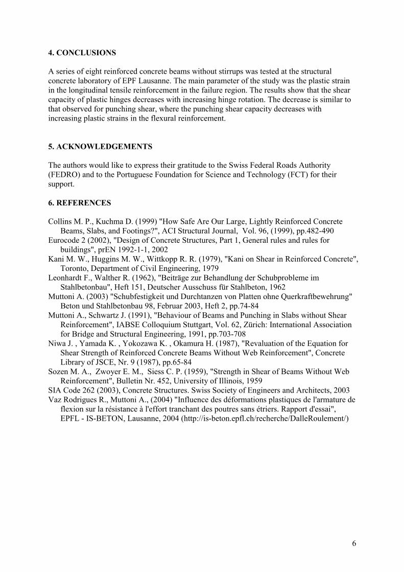
0.5) was generally smaller with increasing rotation θ, except for beam SR-7. For a detailed description of the test results, see the complete test report (Vaz Rodrigues, 2004). Tab. 3 Failure type, normalized shear strength and rotation at failure for all beams
Failure type
Crack pattern after failure
c
R
fdbV⋅⋅
θ [mrad]
SR-5 Flexural with bar fracture
Q
0.062 68.1
SR-8 Shear with
plastic strains
0.072 47.2
SR-4 Shear with
plastic strains
0.084 40.0
SR-7 Shear with
plastic strains*) First failure Second failure
0.095 63.9
SR-3 Shear with
plastic strains
0.099 28.7
SR-9 Shear with few plastic strains*)
Second failure
First failure 0.113 4.9
SR-6 Shear with few plastic strains*)
First failure Second failure
0.121 6.9
SR-2 Shear with few plastic
strains B
0.136 5.1
*) Only the first failure is considered here
6
4. CONCLUSIONS A series of eight reinforced concrete beams without stirrups was tested at the structural concrete laboratory of EPF Lausanne. The main parameter of the study was the plastic strain in the longitudinal tensile reinforcement in the failure region. The results show that the shear capacity of plastic hinges decreases with increasing hinge rotation. The decrease is similar to that observed for punching shear, where the punching shear capacity decreases with increasing plastic strains in the flexural reinforcement. 5. ACKNOWLEDGEMENTS The authors would like to express their gratitude to the Swiss Federal Roads Authority (FEDRO) and to the Portuguese Foundation for Science and Technology (FCT) for their support. 6. REFERENCES Collins M. P., Kuchma D. (1999) "How Safe Are Our Large, Lightly Reinforced Concrete
Beams, Slabs, and Footings?", ACI Structural Journal, Vol. 96, (1999), pp.482-490 Eurocode 2 (2002), "Design of Concrete Structures, Part 1, General rules and rules for
buildings", prEN 1992-1-1, 2002 Kani M. W., Huggins M. W., Wittkopp R. R. (1979), "Kani on Shear in Reinforced Concrete",
Toronto, Department of Civil Engineering, 1979 Leonhardt F., Walther R. (1962), "Beiträge zur Behandlung der Schubprobleme im
Stahlbetonbau", Heft 151, Deutscher Ausschuss für Stahlbeton, 1962 Muttoni A. (2003) "Schubfestigkeit und Durchtanzen von Platten ohne Querkraftbewehrung"
Beton und Stahlbetonbau 98, Februar 2003, Heft 2, pp.74-84 Muttoni A., Schwartz J. (1991), "Behaviour of Beams and Punching in Slabs without Shear
Reinforcement", IABSE Colloquium Stuttgart, Vol. 62, Zürich: International Association for Bridge and Structural Engineering, 1991, pp.703-708
Niwa J. , Yamada K. , Yokozawa K. , Okamura H. (1987), "Revaluation of the Equation for Shear Strength of Reinforced Concrete Beams Without Web Reinforcement", Concrete Library of JSCE, Nr. 9 (1987), pp.65-84
Sozen M. A., Zwoyer E. M., Siess C. P. (1959), "Strength in Shear of Beams Without Web Reinforcement", Bulletin Nr. 452, University of Illinois, 1959
SIA Code 262 (2003), Concrete Structures. Swiss Society of Engineers and Architects, 2003 Vaz Rodrigues R., Muttoni A., (2004) "Influence des déformations plastiques de l'armature de
flexion sur la résistance à l'effort tranchant des poutres sans étriers. Rapport d'essai", EPFL - IS-BETON, Lausanne, 2004 (http://is-beton.epfl.ch/recherche/DalleRoulement/)