Experimental Evaluation of Antenna Polarization and ...
10
Experimental Evaluation of Antenna Polarization and Elevation Effects on Drone Communications Mahmoud Badi, John Wensowitch, Dinesh Rajan, and Joseph Camp Southern Methodist University {mbadi,jwensowitch,rajand,camp}@smu.edu ABSTRACT In the next wave of swarm-based applications, unmanned aerial vehicles (UAVs) need to communicate with peer drones in any direc- tion of a three-dimensional (3D) space. On a given drone and across drones, various antenna positions and orientations are possible. We know that, in free space, high levels of signal loss are expected if the transmitting and receiving antennas are cross polarized. How- ever, increasing the reflective and scattering objects in the channel between a transmitter and receiver can cause the received polar- ization to become completely independent from the transmitted polarization, making the cross-polarization of antennas insignif- icant. Usually, these effects are studied in the context of cellular and terrestrial networks and have not been analyzed when those objects are the actual bodies of the communicating drones that can take different relative directions or move at various elevations. In this work, we show that the body of the drone can affect the received power across various antenna orientations and positions and act as a local scatterer that increases channel depolarization, re- ducing the cross-polarization discrimination (XPD). To investigate these effects, we perform experimentation that is staged in terms of complexity from a controlled environment of an anechoic cham- ber with and without drone bodies to in-field environments where drone-mounted antennas are in-flight with various orientations and relative positions with the following outcomes: (i.) drone relative direction can significantly impact the XPD values, (ii.) elevation an- gle is a critical factor in 3D link performance, (iii.) antenna spacing requirements are altered for co-located cross-polarized antennas, and (iv.) cross-polarized antenna setups more than double spectral efficiency. Our results can serve as a guide for accurately simulating and modeling UAV networks and drone swarms. 1 INTRODUCTION The commercial use of UAVs, in addition to military applications, has been exponentially increasing. In 2017, the number of commer- cial drones increased by 58% in North America compared to 2016 with a projected global market of $11.61 billion by 2022 [1]. With the new advancements in UAVs such as the ability to hover and rapidly change locations and respond to control commands, UAVs are becoming more attractive to many organizations in a diversified Permission to make digital or hard copies of all or part of this work for personal or classroom use is granted without fee provided that copies are not made or distributed for profit or commercial advantage and that copies bear this notice and the full citation on the first page. Copyrights for components of this work owned by others than ACM must be honored. Abstracting with credit is permitted. To copy otherwise, or republish, to post on servers or to redistribute to lists, requires prior specific permission and/or a fee. Request permissions from [email protected]. MSWiM ’19, November 25–29, 2019, Miami Beach, FL, USA © 2019 Association for Computing Machinery. ACM ISBN 978-1-4503-6904-6/19/11. . . $15.00 https://doi.org/10.1145/3345768.3355916 array of applications (e.g., inspection, mapping, monitoring). The next wave of these and other applications will be coordination of drone swarms to achieve automated tasks, leading researchers to extensively study UAV-based communications. The majority of lit- erature, however, focuses on simulations ([2] and references within) or optimization models that target the optimal placement of a UAV [3–6] in various applications. These methods are important research tools and give valuable insight but may be misleading if these tools are not grounded in reality. Recently, measurement-based studies have been conducted with the majority of them focusing on air-to- ground (AtG) communications [7–13]. Experiments that investigate air-to-air (AtA) links mainly focus on received signal variations with distance and finding path-loss exponents with little emphasis on the body effects, antenna radiation pattern, polarization, and their joint effects. For example, authors in [14] measure the received signal strength (RSS) over various altitudes and empirically model the ground effects on multipath propagation. Furthermore, authors in [15] investigate network performance of AtA and AtG links in different network topologies and measure throughput at various distances and find the path-loss exponent. More elaborate details on related work are presented in §5. As drones are expected to communicate in swarms, carry 5G traf- fic, and be integrated in IoT applications [6, 9], drone-based MIMO systems that offer higher throughput and more robust airborne links are becoming more attractive than ever [11–13]. However, it is well known that the capacity of these MIMO systems can be significantly reduced due to high spatial correlation of its channels [26, 33]. The MIMO spatial correlation is known to largely depend on antenna spacing, radiation pattern and polarization; factors that are found to be crucial when modeling polarized MIMO [25–28] channels in 3D. These factors are of particular interest to us because of the unique form factor and the potential effects of the body on the radiation pattern and polarization, the ability to move freely in 3D space (i.e., in elevation and azimuth planes), and the limited space on UAVs, which might pose a challenge on antenna spacing and correlation in MIMO applications. Cross-polarization discrimination (XPD) has a significant im- pact on the spatial correlation of the MIMO channel [26, 33] and according to the geometrical theory of channel depolarization [24] and measurement campaigns [25], depends largely on the envi- ronment and local scatterers around a receiving body. However, none of the current works that model 3D UAV channels [30, 31] investigate and quantify the impact of the drone body on XPD. In this paper, we experimentally measure how the drone body can affect the received power and XPD in different blocking scenarios. Furthermore, as elevation between drones can cause polarization mismatch and consequent power losses, we measure the RSS in a UAV-to-UAV link at different elevation angles for six different Session: Performance Evaluation MSWiM ’19, November 25–29, 2019, Miami Beach, FL, USA 211
Transcript of Experimental Evaluation of Antenna Polarization and ...

Experimental Evaluation of Antenna Polarization and ElevationEffects on Drone Communications
Mahmoud Badi, John Wensowitch, Dinesh Rajan, and Joseph CampSouthern Methodist University
mbadi,jwensowitch,rajand,[email protected]
ABSTRACTIn the next wave of swarm-based applications, unmanned aerialvehicles (UAVs) need to communicate with peer drones in any direc-tion of a three-dimensional (3D) space. On a given drone and acrossdrones, various antenna positions and orientations are possible. Weknow that, in free space, high levels of signal loss are expected ifthe transmitting and receiving antennas are cross polarized. How-ever, increasing the reflective and scattering objects in the channelbetween a transmitter and receiver can cause the received polar-ization to become completely independent from the transmittedpolarization, making the cross-polarization of antennas insignif-icant. Usually, these effects are studied in the context of cellularand terrestrial networks and have not been analyzed when thoseobjects are the actual bodies of the communicating drones thatcan take different relative directions or move at various elevations.In this work, we show that the body of the drone can affect thereceived power across various antenna orientations and positionsand act as a local scatterer that increases channel depolarization, re-ducing the cross-polarization discrimination (XPD). To investigatethese effects, we perform experimentation that is staged in termsof complexity from a controlled environment of an anechoic cham-ber with and without drone bodies to in-field environments wheredrone-mounted antennas are in-flight with various orientations andrelative positions with the following outcomes: (i.) drone relativedirection can significantly impact the XPD values, (ii.) elevation an-gle is a critical factor in 3D link performance, (iii.) antenna spacingrequirements are altered for co-located cross-polarized antennas,and (iv.) cross-polarized antenna setups more than double spectralefficiency. Our results can serve as a guide for accurately simulatingand modeling UAV networks and drone swarms.
1 INTRODUCTIONThe commercial use of UAVs, in addition to military applications,has been exponentially increasing. In 2017, the number of commer-cial drones increased by 58% in North America compared to 2016with a projected global market of $11.61 billion by 2022 [1]. Withthe new advancements in UAVs such as the ability to hover andrapidly change locations and respond to control commands, UAVsare becoming more attractive to many organizations in a diversified
Permission to make digital or hard copies of all or part of this work for personal orclassroom use is granted without fee provided that copies are not made or distributedfor profit or commercial advantage and that copies bear this notice and the full citationon the first page. Copyrights for components of this work owned by others than ACMmust be honored. Abstracting with credit is permitted. To copy otherwise, or republish,to post on servers or to redistribute to lists, requires prior specific permission and/or afee. Request permissions from [email protected] ’19, November 25–29, 2019, Miami Beach, FL, USA© 2019 Association for Computing Machinery.ACM ISBN 978-1-4503-6904-6/19/11. . . $15.00https://doi.org/10.1145/3345768.3355916
array of applications (e.g., inspection, mapping, monitoring). Thenext wave of these and other applications will be coordination ofdrone swarms to achieve automated tasks, leading researchers toextensively study UAV-based communications. The majority of lit-erature, however, focuses on simulations ([2] and references within)or optimization models that target the optimal placement of a UAV[3–6] in various applications. Thesemethods are important researchtools and give valuable insight but may be misleading if these toolsare not grounded in reality. Recently, measurement-based studieshave been conducted with the majority of them focusing on air-to-ground (AtG) communications [7–13]. Experiments that investigateair-to-air (AtA) links mainly focus on received signal variationswith distance and finding path-loss exponents with little emphasison the body effects, antenna radiation pattern, polarization, andtheir joint effects. For example, authors in [14] measure the receivedsignal strength (RSS) over various altitudes and empirically modelthe ground effects on multipath propagation. Furthermore, authorsin [15] investigate network performance of AtA and AtG links indifferent network topologies and measure throughput at variousdistances and find the path-loss exponent. More elaborate detailson related work are presented in §5.
As drones are expected to communicate in swarms, carry 5G traf-fic, and be integrated in IoT applications [6, 9], drone-based MIMOsystems that offer higher throughput and more robust airbornelinks are becoming more attractive than ever [11–13]. However,it is well known that the capacity of these MIMO systems can besignificantly reduced due to high spatial correlation of its channels[26, 33]. The MIMO spatial correlation is known to largely dependon antenna spacing, radiation pattern and polarization; factors thatare found to be crucial when modeling polarized MIMO [25–28]channels in 3D. These factors are of particular interest to us becauseof the unique form factor and the potential effects of the body onthe radiation pattern and polarization, the ability to move freelyin 3D space (i.e., in elevation and azimuth planes), and the limitedspace on UAVs, which might pose a challenge on antenna spacingand correlation in MIMO applications.
Cross-polarization discrimination (XPD) has a significant im-pact on the spatial correlation of the MIMO channel [26, 33] andaccording to the geometrical theory of channel depolarization [24]and measurement campaigns [25], depends largely on the envi-ronment and local scatterers around a receiving body. However,none of the current works that model 3D UAV channels [30, 31]investigate and quantify the impact of the drone body on XPD. Inthis paper, we experimentally measure how the drone body canaffect the received power and XPD in different blocking scenarios.Furthermore, as elevation between drones can cause polarizationmismatch and consequent power losses, we measure the RSS ina UAV-to-UAV link at different elevation angles for six different
Session: Performance Evaluation MSWiM ’19, November 25–29, 2019, Miami Beach, FL, USA
211
antenna orientation combinations to determine which antenna ori-entations are best to cover movement in 3D space. Based on ourresults, we accurately model drone networks with an awareness ofantenna spacing and orientations and relative elevations for usein simulation or real-world deployments. Our contributions in thispaper are as follows.
• We build a UAV-based 1 × 2 diversity system using SoftwareDefined Radio (SDR) to explore the effects of the UAV body,elevation and antenna orientation on the performance ofUAV-to-UAV links.
• In an anechoic chamber, we experimentally characterizethe effects of the designed UAV platform and show thatthe drone body significantly impacts channel depolarizationand reduce XPD by an average of 14.5 dB over all azimuthdirections compared to an isolated antenna scenario.
• We perform in-field measurements and characterize thebody-induced losses on RSS when two drones move in dif-ferent azimuth directions at the same altitude. We show thatthe relative direction of one drone to another can reduceRSS by up to 16 dB compared to when the two drones areexactly facing each other. Based on this finding, we proposea range of body excess loss that should be added to the con-ventional log-distance path-loss model for more accuratepredictions of UAV-to-UAV links. This model is shown toachieve a lower absolute error in prediction by 89% comparedto the conventional model.
• We perform in-field measurements on the impact of the ele-vation angle on RSS and SNR improvements due to diversityfor six different antenna orientation combinations. We findthat when the two drones are facing each other, performanceof UAV-to-UAV links in 3D space is mainly driven by theelevation angle. We show that the average RSS can changeby more than 30 dB, even when the polarization is matched.
• We provide recommendations on antenna placement andorientations based on our measurement results. We find that,in general, a 2
3λ is enough spacing to achieve a correlationcoefficient that is less than 0.7. Furthermore, in order toachieve the best performance in UAV-to-UAV links in 3Dspace, we show that horizontal antennas perform betterthan vertical antennas when near locations that are aboveor below the transmit drone while other locations are bestcovered by vertical antennas.
This paper is organized as follows. We present a baseline under-standing of the effects of the drone body on co-polarized and cross-polarized channels and XPD degradation in §2. In §3, we reportresults from in-field experiments that demonstrate the impact ofthe drone body and relative direction on RSS and cross-polarizedchannels and propose an initial model that takes body-inducedlosses into account to provide more accurate large-scale fadingpredictions. Then, in §4, we discuss correlation, antenna placement,and the impact of elevation angle on RSS and diversity. Relatedwork is discussed in §5, and we conclude in §6.
2 BASELINE UNDERSTANDING OF DRONEBODY EFFECTS USING ANECHOICCHAMBER MEASUREMENTS
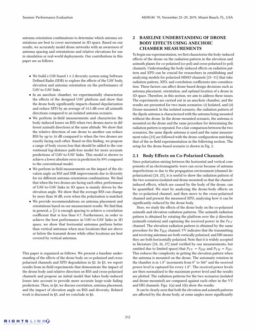
To begin our experimentation, we first characterize the body-inducedeffects of the drone on the radiation pattern in the elevation andazimuth planes for co-polarized (co-pol) and cross-polarized (x-pol)channels. Understanding the body-induced effects on radiation pat-tern and XPD can be crucial for researchers in establishing andanalyzing models for polarized MIMO channels [25–31] that takeradiation pattern, XPD, and correlation coefficients into considera-tion. These factors can affect drone-based design decisions such asantenna placement, orientation, and optimal location of a drone in3D space. Therefore, in this section, we aim to address these issues.The experiments are carried out in an anechoic chamber, and theresults are presented for two main scenarios: (i) Isolated, and (ii)Drone-mounted. In the isolated scenario, the radiation pattern ofthe dipole antenna is characterized with the antenna beingmountedwithout the drone. In the drone-mounted scenario, the antenna ismounted on the drone and the same procedure for determining theradiation pattern is repeated. For a fair comparison between the twoscenarios, the same dipole antenna is used and the same measure-ment rules [23] are followed with the drone configuration matchingthat of the in-field experimentation in the following section. Thesetup for the drone-based scenario is shown in Fig. 2.
2.1 Body Effects on Co-Polarized ChannelsSince polarization mixing between the horizontal and vertical com-ponents of an electromagnetic wave can occur because of antennaimperfections or due to the propagation environment (channel de-polarization) [24, 25], it is useful to show the radiation pattern ofthe two scenarios (isolated and drone mounted) so that the channel-induced effects, which are caused by the body of the drone, canbe quantified. We start by analyzing the drone-body effects onthe co-polarized channel, and then move to the cross-polarizedchannel and present the measured XPD, analyzing how it can besignificantly reduced by the drone body.
Here, we study the effects of the drone body on the co-polarizedazimuth and elevation radiation patterns. The azimuth radiationpattern is obtained by rotating the platform over the ϕ direction(azimuth rotation) and capturing the received power in the PVVchannel. The elevation radiation pattern is obtained by the sameprocedure for the PHH channel; VV indicates that the transmittingand receiving antennas are both vertically polarized, and HHmeansthey are both horizontally polarized. Note that it is widely acceptedin literature [24, 26, 27] (and verified by our measurements, butomitted due to limited space) that PVV = PHH and PVH = PHV .This reduces the complexity in getting the elevation pattern whenthe antenna is mounted on the drone. The automatic rotation inthe chamber is in 1.8 increments from 0 to 360 and the receivedpower level is captured for every 1.8. The received power levelsare then normalized to the maximum power level and the resultsare plotted. The radiation patterns for the two scenarios (isolatedand drone-mounted) are compared against each other in the VVand HH channels. Figs. 1(a) and 1(b) show the results.
It can be clearly seen that both the elevation and azimuth patternsare affected by the drone body, at some angles more significantly
Session: Performance Evaluation MSWiM ’19, November 25–29, 2019, Miami Beach, FL, USA
212

0
30
60
90
120
150
180
210
240
270
300
330
-40
-30
-20
-10
0
Isolated
Antenna on Drone
(a)
0
30
60
90
120
150
180
210
240
270
300
330
-50
-30
-20
-10
0
Isolated
Antenna On Drone
(b)
0
30
60
90
120
150
180
210
240
270
300
330
-50
-30
-20
-10
0
Co-pol (Isolated)
X-pol (Isolated)
XPD=34 dB
(c)
0
30
60
90
120
150
180
210
240
270
300
330
-50
-30
-20
-10
0
Co-pol - Antenna on Drone
X-pol - Antenna on Drone
XPD=13.35 dB
(d)
Figure 1: Effects of the drone body on co-polarized azimuth (a) and elevation (b) radiation patterns for two scenarios: isolated(no drone), and drone-mounted. Effects of the drone body on cross-polarized power levels andXPDwhen the receiving antennais isolated (c) and drone-mounted (d).
Figure 2: Anechoic chamber characterization of the radia-tion pattern when the antenna is mounted on the drone(Drone-mounted scenario) for the PVV channel.than others. In the azimuth plane, we can see that the drone body canreduce the received power by a maximum of 11 dB approximatelywhen the drone is facing away (around ϕ = 210). This resultagrees with many other findings in literature [9–11, 14]. In theelevation plane, we can see that the effect of the body is moresignificant and less symmetrical when compared to the isolatedcase. We can see that the received power when the antenna ismounted on the drone can be reduced by up to (max difference)18 dB compared to the isolated case. It is worth mentioning that thesame experiments were conducted for another antenna position onthe drone (right position in Fig. 2) and, albeit a different radiationpattern was obtained, similar differences in values (average andstandard deviations) were found.
The min, max, average, and standard deviation of the differencein power levels between the isolated and the drone-mounted casein the azimuth and elevation planes are denoted by Łazimuth andŁelevation and defined as PVV ,isolated −PVV ,drone−mounted andPHH,isolated −PHH,drone−mounted for the azimuth and elevationplanes, respectively. The results are summarized in Table 1.Table 1: Body-Induced Losses on co-polarized azimuth andelevation power levels
Plane Min. Max. Avg. SDŁazimuth (dB) 0.016 10.96 3.03 2.53Łelevation (dB) 0.02 18.72 4.13 4.06
2.2 Body Effects on Cross-Polarized ChannelsIn this section, we analyze the impact of the drone body on thecross-polarization discrimination (XPD), which describes how wellthe two orthogonal polarization components can be separated. XPDis calculated as the ratio of the amount of power received in theco-polarized versus cross-polarized directions [28]:
XPD = Pcopol /Pxpol (1)
Here, we present results of the PHH (black solid lines in Figs. 1(c)and 1(d)) and PVH (red lines in the same figures) and calculatethe difference between the two as the angle-specific XPD value. Itis well known that channel induced XPD can vary depending onthe distance, environment (LOS or NLOS), and the angle betweentransmitters and receivers[25]. This is because of the variations inthe number and nature of scatterers along the path between thetransmit and receive antennas. In scenarios where multipath doesnot exist, and for identical antennas at the same orientation angle,the XPD is found to be approximately constant and independentof distance [32]. Therefore, it is expected that a higher amount ofpolarization mixing might occur due to reflections from the dronebody surrounding the antenna, and, as a result, lower XPD valuesare expected in the drone-mounted scenario. From Fig. 1(d) we cansee a clear impact of the drone body on the cross-polarized powermeasured by the receiving antenna when it is mounted on thedrone. Even when the receiving antenna (when drone-mounted) isdirectly facing the transmitter (ϕ = 0), the drone body can reducethe the XPD by approx. 9 dB (from 24 dB in the isolated scenario to15 dB when drone-mounted). More significant reduction appearswhen the drone is facing-away with an XPD reduction by 20.6dB. We find that, on average over all angles, the XPD is reducedfrom 19.2 dB in the isolated case to 4.6 dB when drone-mounted.In addition, the maximum XPD in the isolated case is found tobe 41.15 dB as opposed to 28.02 dB in the drone-mounted case.Results are summarized in Table 2. These are significant findingsdue to the impact that XPD can have on correlation and achievedcapacity in MIMO [33] or diversity applications [34] that leveragedifferently-polarized channels. For example, an average XPD valueof 0 dB means that the rank of the MIMO channel is 1. Hence,spatial multiplexing is not possible [33]. On the other hand, thesame 0 dB value can indicate a richness of scatterers in themultipathenvironment, which leads to a low correlation coefficient and highdiversity gains [29]. Surprisingly, and to the best of our knowledge,there is no prior work that characterizes polarization mixing andXPD degradation due to the sole effects of the drone body.
Table 2: XPD in The Isolated and Drone-mounted Scenarios
Setup Min. Max. Avg. SDXPDisolated (dB) -10.14 41.15 19.22 8.17
XPDdrone−mounted (dB) -19.23 28.02 4.61 8.41
Session: Performance Evaluation MSWiM ’19, November 25–29, 2019, Miami Beach, FL, USA
213

(a) Location(50-110 m height). (b) Receiver drone setup.
Figure 3: In-field experiment locationwith receiver in centerand transmitter in pictured locations along four cardinal di-rections (a). UAV-based SDR platform for the receiver dronewith two (VU and VD) of the three antenna orientations(b).
After understanding the effect of the drone body on the receivedpower in polarized channels, it is now possible to experimentallyanalyze (in-field) UAV-to-UAV links with different antenna orienta-tions and at different elevation angles to understand the impact ofthe drone body and its location in space on performance.
3 IN-FIELD EXPERIMENTS: BODY-INDUCEDEFFECTS ON POLARIZED AIR-TO-AIRCHANNELS
In this section, we investigate the body-induced effects on thereceived signal strength when the transmitting drone moves in fourrelative directions (North, South, East, and West) to the receivingdrone; this means that it can be in front of (North), on the side(East or West), or behind (South) the receiving drone. Thus, the RSSmay be affected differently depending on the transmitter’s relativelocation. First, we explain the experimental setup and procedure.Then, we discuss measurement results and show how a predictionthat is based only on a log-distance path loss model can significantlydiffer from the measured values because of the drone body-inducedeffects. Finally, we quantify these effects and give a range of valuesof excess loss that might be added to the conventional path-lossmodel to obtain more accurate predictions of the RSS in UAV-to-UAV links. The results presented here can be integrated in simulatedor in-field environments where multiple different connections (e.g.,in swarms) are needed on different sides of the drone and relativedirection becomes an important aspect in decisions made by dronesthat aim to optimize their links [19].
3.1 Hardware and Software SetupWe use the Universal Software Radio Peripheral (USRP) Ettus E312,which is a battery-operated 2 × 2 MIMO software defined radioplatform with an operational frequency range of 70 MHz – 6 GHzand up to 56 MHz of instantaneous bandwidth. The transmissionpower of the USRP at 2.5 GHz was calibrated by connecting theUSRP to a Rohde and Schwarz FSH8 Spectrum Analyzer using anSMA connector and a 50Ω cable, and a measured value of 6.2 dBmwas recorded. Then, using GNU Radio blocks and through a Pythonscript, we configure the transmitter to send a constant envelopesinusoid at a sampling rate of 32k samples/second and build areceiver that can simultaneously record the received signal on two
receiving RF chains through two antennas mounted at a distanceof 2
3λ where λ is the wavelength of the transmitted carrier. Wedevelop shell scripts that perform GPS logging and capture velocity,altitude, and IMU data while the drones are hovering. These sensormeasurements are then used in splicing the data sets for analysis.
Using a ROBO 3D printer and MatterControl (printing software),we design and 3D print mounts for the USRP and antennas tobe installed on a DJI Matrice 100 drone. Three different antennamounts are built: vertical up (VU), horizontal (H), and verticaldown (VD). In this set of experiments, the VU and H orientationsare implemented at the receiver while the transmitting drone hasa VU antenna orientation. The VD mount is used for the next setof experiments where we explore elevation effects. These antennamounts are securely fastened to the central frame on the front of theMatrice 100. The placement decision was based on the measuredstability against vibrations while maintaining the load of the USRPat the center of the drone body. Furthermore, it is often desired tofocus electromagnetic energy at some directions more than others,which might dictate the placement decisions of the antennas ona drone [9, 10, 12] to be on a certain side. The in-phase (rI ) andquadrature (rQ ) components of the received signal of both RF chainsare stored in a .dat file. Then, the signal envelope |r | is obtained as|r | =
√r2I + r
2Q . The received power is calculated and a per-location
analysis is carried out according to sensor measurements.
3.2 Experiment ProcedureThroughout this set of experiments, the heading direction (whichcorresponds to the locations of the antennas in our experiments) forboth UAVs is North.We fly the receiving UAV and let it continuouslyhover at a 60-m altitude in the same location (fixed) throughoutall experiments while the transmitting UAV moves in the sameplane. The transmitting drone starts at 20 m away in each cardinaldirection (North, South, East, and West) and then flies in 20-mincrements away from the receiving drone until it reaches 100 mof separation distance, creating 5 distinct hovering locations perdirection, each at a height of 60 m (i.e., these hovering locationsare all at the same altitude). We define each experiment by itscorresponding relative transmit drone direction. For example, anEast experiment means that, with both UAVs facing North, thetransmitting UAV moves linearly, 20 m away from the receivingdrone in the East direction (see Fig. 3(a)).
3.3 Relative Direction and Body Effects on RSSGiven that no obstacles exist in the path between the two UAVswith negligible ground effects on multipath at 60 m altitude [14],one would expect that the relative direction of one drone to theother would not result in significant variations in received signallevels. Interestingly, our results show that the relative directionof the drone and its body placement with respect to its receivingantennas can result in a different RSS of up to 16 dB. If we look atthe results of the least squares fitting of the average RSS values inFig. 4, we see how signal reception can significantly vary accordingto the relative direction of the transmitting drone. For example, at40 m distance, when the transmit drone is in the relative Northdirection, the average received signal is 12 dB higher than when itis in the South direction. This additional loss due to the drone body
Session: Performance Evaluation MSWiM ’19, November 25–29, 2019, Miami Beach, FL, USA
214
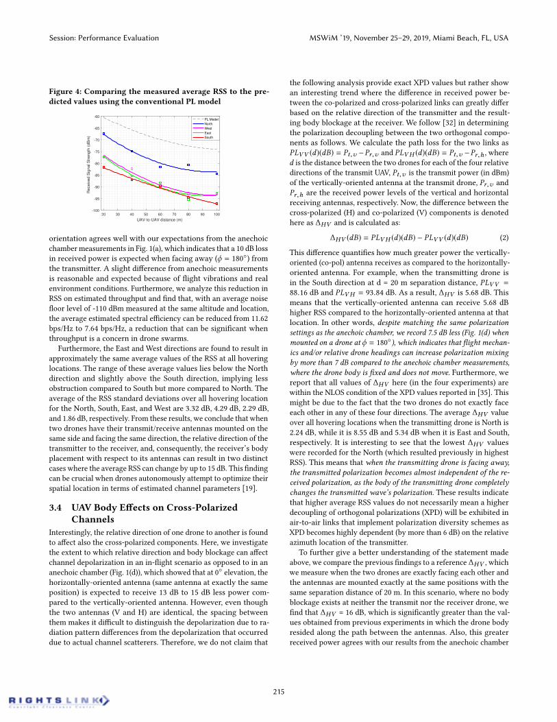
Figure 4: Comparing the measured average RSS to the pre-dicted values using the conventional PL model
20 30 40 50 60 70 80 90 100
UAV-to-UAV distance (m)
-100
-95
-90
-85
-80
-75
-70
-65
-60
Receiv
ed S
ignal S
trength
(dB
m)
PL Model
North
West
East
South
orientation agrees well with our expectations from the anechoicchamber measurements in Fig. 1(a), which indicates that a 10 dB lossin received power is expected when facing away (ϕ = 180) fromthe transmitter. A slight difference from anechoic measurementsis reasonable and expected because of flight vibrations and realenvironment conditions. Furthermore, we analyze this reduction inRSS on estimated throughput and find that, with an average noisefloor level of -110 dBm measured at the same altitude and location,the average estimated spectral efficiency can be reduced from 11.62bps/Hz to 7.64 bps/Hz, a reduction that can be significant whenthroughput is a concern in drone swarms.
Furthermore, the East and West directions are found to result inapproximately the same average values of the RSS at all hoveringlocations. The range of these average values lies below the Northdirection and slightly above the South direction, implying lessobstruction compared to South but more compared to North. Theaverage of the RSS standard deviations over all hovering locationfor the North, South, East, and West are 3.32 dB, 4.29 dB, 2.29 dB,and 1.86 dB, respectively. From these results, we conclude that whentwo drones have their transmit/receive antennas mounted on thesame side and facing the same direction, the relative direction of thetransmitter to the receiver, and, consequently, the receiver’s bodyplacement with respect to its antennas can result in two distinctcases where the average RSS can change by up to 15 dB. This findingcan be crucial when drones autonomously attempt to optimize theirspatial location in terms of estimated channel parameters [19].
3.4 UAV Body Effects on Cross-PolarizedChannels
Interestingly, the relative direction of one drone to another is foundto affect also the cross-polarized components. Here, we investigatethe extent to which relative direction and body blockage can affectchannel depolarization in an in-flight scenario as opposed to in ananechoic chamber (Fig. 1(d)), which showed that at 0 elevation, thehorizontally-oriented antenna (same antenna at exactly the sameposition) is expected to receive 13 dB to 15 dB less power com-pared to the vertically-oriented antenna. However, even thoughthe two antennas (V and H) are identical, the spacing betweenthem makes it difficult to distinguish the depolarization due to ra-diation pattern differences from the depolarization that occurreddue to actual channel scatterers. Therefore, we do not claim that
the following analysis provide exact XPD values but rather showan interesting trend where the difference in received power be-tween the co-polarized and cross-polarized links can greatly differbased on the relative direction of the transmitter and the result-ing body blockage at the receiver. We follow [32] in determiningthe polarization decoupling between the two orthogonal compo-nents as follows. We calculate the path loss for the two links asPLVV (d)(dB) = Pt,v −Pr,v and PLVH (d)(dB) = Pt,v −Pr,h , whered is the distance between the two drones for each of the four relativedirections of the transmit UAV, Pt,v is the transmit power (in dBm)of the vertically-oriented antenna at the transmit drone, Pr,v andPr,h are the received power levels of the vertical and horizontalreceiving antennas, respectively. Now, the difference between thecross-polarized (H) and co-polarized (V) components is denotedhere as ∆HV and is calculated as:
∆HV (dB) = PLVH (d)(dB) − PLVV (d)(dB) (2)
This difference quantifies how much greater power the vertically-oriented (co-pol) antenna receives as compared to the horizontally-oriented antenna. For example, when the transmitting drone isin the South direction at d = 20 m separation distance, PLVV =88.16 dB and PLVH = 93.84 dB. As a result, ∆HV is 5.68 dB. Thismeans that the vertically-oriented antenna can receive 5.68 dBhigher RSS compared to the horizontally-oriented antenna at thatlocation. In other words, despite matching the same polarizationsettings as the anechoic chamber, we record 7.5 dB less (Fig. 1(d) whenmounted on a drone at ϕ = 180), which indicates that flight mechan-ics and/or relative drone headings can increase polarization mixingby more than 7 dB compared to the anechoic chamber measurements,where the drone body is fixed and does not move. Furthermore, wereport that all values of ∆HV here (in the four experiments) arewithin the NLOS condition of the XPD values reported in [35]. Thismight be due to the fact that the two drones do not exactly faceeach other in any of these four directions. The average ∆HV valueover all hovering locations when the transmitting drone is North is2.24 dB, while it is 8.55 dB and 5.34 dB when it is East and South,respectively. It is interesting to see that the lowest ∆HV valueswere recorded for the North (which resulted previously in highestRSS). This means that when the transmitting drone is facing away,the transmitted polarization becomes almost independent of the re-ceived polarization, as the body of the transmitting drone completelychanges the transmitted wave’s polarization. These results indicatethat higher average RSS values do not necessarily mean a higherdecoupling of orthogonal polarizations (XPD) will be exhibited inair-to-air links that implement polarization diversity schemes asXPD becomes highly dependent (by more than 6 dB) on the relativeazimuth location of the transmitter.
To further give a better understanding of the statement madeabove, we compare the previous findings to a reference ∆HV , whichwe measure when the two drones are exactly facing each other andthe antennas are mounted exactly at the same positions with thesame separation distance of 20 m. In this scenario, where no bodyblockage exists at neither the transmit nor the receiver drone, wefind that ∆HV = 16 dB, which is significantly greater than the val-ues obtained from previous experiments in which the drone bodyresided along the path between the antennas. Also, this greaterreceived power agrees with our results from the anechoic chamber
Session: Performance Evaluation MSWiM ’19, November 25–29, 2019, Miami Beach, FL, USA
215
measurements (Fig. 1(d)), signaling the loss is more due to the dronebody than the in-flight vibrations. Furthermore, this value agreeswith the LOS XPD values range found in [25, 35]. With these ex-perimental findings, we conclude that: (i.) the relative directionof a transmitter drone to another can affect both the average RSSin a co-polarized channel by 16 dB and the decoupling betweenorthogonally-polarized waves represented by XPD by more than14 dB, (ii.) unless the two drones are facing each other ∆HV , whichrepresents XPD in our field experiments, is reported to fall in theNLOS range of the XPD values reported in [35], and (iii.) when thetwo drones are facing each other, we find that ∆HV = 16 dB, whichis the highest value compared to the different relative direction sce-narios and agrees well with the LOS XPDmeasurements reported in[25, 35]. These findings would be valuable to researchers whenmod-eling and deploying UAV swarms that incorporate various antennaorientations and move freely in any direction.
Table 3: Additional Drone Body Losses Per Hovering Loca-tion When Tx Drone is in The North and South Directions
Avg.lossDistance 20m 40m 60m 80m 100m
Γ0 (dB) 6.92 8.97 10.05 10.26 9.66Γ180 (dB) 21.16 20.66 20.7 21.58 23.15
3.5 Body-Induced Effects on PredictingLarge-Scale Fading
In this section, we discuss how predicting the performance of UAV-to-UAV links can give erroneous results if the blockage created bythe different relative directions is not taken into consideration. Weuse the path-loss model given by [12, 14]:
Pr = Pt − PL(do ) − 10αloд(d/do ) + ξs (3)
Here, Pr and Pt are the received and transmitted power (in dBm),respectively. PL(do ) is the path loss at a reference distance (do )and is given by PL(do ) = 20loд(4πdo/λ), and d is the distancebetween the transmitter and receiver. The shadowing parameter ξsis normally distributed with zero mean, and a standard deviationσ in dB. Finally, α is the path loss exponent, which is known todepend largely on the surrounding environment of the transmitterand receiver and found to be close to 2 in many drone-to-dronelinks [7]. In this model, the transmit power is 6.2 dBm, and thestandard deviation of the shadowing parameter is chosen to beσ = 2 dB. The measured reference path loss (PL(do ) at do = 20 m)with both UAVs facing each other (PL = 67.7 dB) is found to be veryclose to the free-space path-loss at this distance (PL = 66.41 dB),which indicates that when UAVs are facing each other. No additionaldrone body losses need to be included and the log-distance path-lossmodel can accurately describe such links [15].
However, this is not the case when drones move in differentdirections from each other. According to our measurements, andas we saw in Fig. 4, when the transmit drone moves in variousrelative directions with respect to the receiving drone, the body ofthe transmitting and receiving drones become an obstacle in thereceived signal’s path causing significant reductions in the averageRSS level (up to 16 dB). We quantify the difference between themeasured PL in the four directions and the PL predicted using the
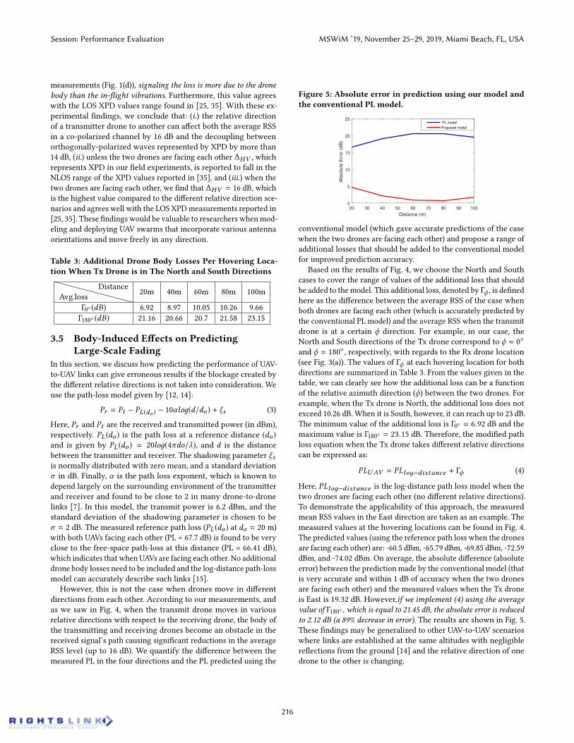
Figure 5: Absolute error in prediction using our model andthe conventional PL model.
20 30 40 50 60 70 80 90 100
Distance (m)
0
5
10
15
20
25
Ab
so
lute
Err
or
(dB
)
PL model
Proposed model
conventional model (which gave accurate predictions of the casewhen the two drones are facing each other) and propose a range ofadditional losses that should be added to the conventional modelfor improved prediction accuracy.
Based on the results of Fig. 4, we choose the North and Southcases to cover the range of values of the additional loss that shouldbe added to the model. This additional loss, denoted by Γϕ , is definedhere as the difference between the average RSS of the case whenboth drones are facing each other (which is accurately predicted bythe conventional PL model) and the average RSS when the transmitdrone is at a certain ϕ direction. For example, in our case, theNorth and South directions of the Tx drone correspond to ϕ = 0and ϕ = 180, respectively, with regards to the Rx drone location(see Fig. 3(a)). The values of Γϕ at each hovering location for bothdirections are summarized in Table 3. From the values given in thetable, we can clearly see how the additional loss can be a functionof the relative azimuth direction (ϕ) between the two drones. Forexample, when the Tx drone is North, the additional loss does notexceed 10.26 dB. When it is South, however, it can reach up to 23 dB.The minimum value of the additional loss is Γ0 = 6.92 dB and themaximum value is Γ180 = 23.15 dB. Therefore, the modified pathloss equation when the Tx drone takes different relative directionscan be expressed as:
PLUAV = PLloд−distance + Γϕ (4)
Here, PLloд−distance is the log-distance path loss model when thetwo drones are facing each other (no different relative directions).To demonstrate the applicability of this approach, the measuredmean RSS values in the East direction are taken as an example. Themeasured values at the hovering locations can be found in Fig. 4.The predicted values (using the reference path loss when the dronesare facing each other) are: -60.5 dBm, -65.79 dBm, -69.85 dBm, -72.59dBm, and -74.02 dBm. On average, the absolute difference (absoluteerror) between the prediction made by the conventional model (thatis very accurate and within 1 dB of accuracy when the two dronesare facing each other) and the measured values when the Tx droneis East is 19.32 dB. However,if we implement (4) using the averagevalue of Γ180 , which is equal to 21.45 dB, the absolute error is reducedto 2.12 dB (a 89% decrease in error). The results are shown in Fig. 5.These findings may be generalized to other UAV-to-UAV scenarioswhere links are established at the same altitudes with negligiblereflections from the ground [14] and the relative direction of onedrone to the other is changing.
Session: Performance Evaluation MSWiM ’19, November 25–29, 2019, Miami Beach, FL, USA
216

4 IMPACT OF ELEVATION ANGLE ON RSSAND DIVERSITY WITH DIFFERENTANTENNA ORIENTATIONS
It is well established in literature that the performance of MIMOsystems highly depends on the spatial correlation of the channel ma-trix. This spatial correlation is found to vary according to changesin the channel induced by different antenna radiation patterns,spacing, orientation, polarization, and elevation and azimuth an-gle of arrivals [26, 27, 33, 34]. In addition, recent studies, such as[36], found that, in drone swarm applications, if all ground stationantennas are identically oriented and a UAV is moving at differentelevation angles, the received signal can be effectively lost due topolarization mismatch. This motivates us to experimentally investi-gate the effects of elevation angle on the RSS with various antennaorientations at the receiver drone in a 1 × 2 receive diversity sys-tem. First, we discuss the experiment procedure. Then, the effectof the elevation angle on RSS for different antenna orientations isanalyzed. After that, we discuss antenna spacing and correlationand conclude the section with SNR gains due to diversity and theirdependence on antenna orientation and elevation.
4.1 Experiment ProcedureIn this set of experiments, the transmitting UAV is hovering at analtitude of 80 m with its transmitting antenna oriented verticallyupward (VU), facing the receiving drone which moves around thetransmitting UAV in a predefined sequence of hovering locations,creating a 3D shape (Fig. 6). Diversity is implemented at the re-ceiving UAV which flies in an automated, repeatable fashion usingwaypoints and resulting in four distinct (negative) angles belowthe transmitter and four (positive) angles above the transmitter.The below and above points are separated by an elevation angleof θelev . = 0. The horizontal distance (dh ) between the Tx andRx drones is 20 m at θelev . = 0 and the angle-specific distance isdθelev .
=√d2h + d
2v , where dv is the vertical distance, which varies
from -30 m (i.e., 50 m above ground) to +30 m (i.e., 110 m aboveground) in 10-m increments. The different elevation angles made (insequence) are: −90, −56.3, −45, −26.5, 0, +26.5, +45, +56.3and +90 and can be calculated as θelev . = arctan(dv/dh ).
Experiments are carried out for six different antenna orientationcombinations (VU-VU, VU-VD, VU-H, VD-VD, H-H and H-VD)where VU, VD, and H represents vertical-up, vertical-down, andhorizontal antenna orientations, respectively. See Fig. 6. The RSSis recorded at each hovering location for 30 s at a sampling rate of32k samples/s and averaged over 10 seconds. The two UAVs are ina perfect LOS condition at a carrier frequency of 2.5 GHz 5 and ameasured average noise floor of -110 dBm. The average RSS valuesare fitted using a second-order polynomial in the range θelev . =−56 to +56, and the results are plotted and analyzed.
4.2 Effect of Elevation Angle on RSSIn this section, we study the dependence of RSS on the elevationangle between two drones for different antenna orientations. In gen-eral, if we look at Figs. 7(a) and 7(b), we observe an expected trendwhere the average RSS follows an arch-like shape in all vertically-oriented antennas in the range θelev . = −56 to +56, with the
Figure 6: 3D experiment setup with 6 Rx antenna orienta-tion combinations in the 1 × 2 diversity system.
strongest average RSS recorded at an elevation angle of θelev . = 0;this is where the two drones exhibit perfect LOS at the same alti-tude. As the receiving drone starts moving up (to 110 m) or down(to 50 m), reductions in the signal level start to appear. These reduc-tions are mainly caused by polarization mismatch and the elevationprofile of the radiation pattern [18], which we characterized in theanechoic chamber (see Fig. 1(b)) for isolated (no drone, antennaonly) and drone-mounted scenarios.
We first analyze results from the vertically-oriented receivers(VD-VD) (Fig. 7(b)) to understand the effect of elevation on RSSbetween two UAVs when the antennas used are identical withmatched orientations (vertical). We can see that the two receivingantennas undergo the same behavior versus the elevation angle.The received signal level increases from around −87 dBm to −67dBm (20 dB increase) when the receiving drone moves from −56.3to 0 elevation angle. Then, as the drone moves higher (from 0 to+56 elevation), the received signal level decreases from -67 dBmto -85 dBm (18 dB decrease), until it reaches around -91 dBm asit reaches exactly above the transmitting drone (+90). When thisreceiving drone moves to the −90 elevation location (right belowthe Tx drone), an average RSS level of -97 dBm is reported. Thistrend is observed for all vertically-oriented receivers.
We conclude here that in an air-to-air links where two droneshave the same antenna types and orientation, movement of thereceiving drone at different elevation angles can reduce the signallevel by up to 30 dB. This 30 dB difference in RSS can be crucialwhen designing algorithms for optimal drone placement [19]. Sim-ilar findings in cellular to UAV and air-to-ground scenarios werereported in [18], and [10]. However, in addition to not coveringair-to-air links, the proximity of the receiver or transmitter to theground in both studies makes it difficult to isolate the elevationfactor from multipath and the surrounding environment.
Furthermore, the nature of drone movement in 3D space andthe low RSS levels measured by vertical antennas at θelev . = |90|motivate us to employ polarization diversity [21] that is representedby using two co-located orthogonally-oriented antennas. If we lookat Fig. 7(a), where we implement a horizontally-oriented (H) receiveantenna in addition to a vertically-oriented (VD) antenna, we cansee that although VD results in higher RSS values throughout mostelevation angles, around +56 the RSS for the H receiver starts toincrease, where lower RSS values for the VD receiver are measured.
Session: Performance Evaluation MSWiM ’19, November 25–29, 2019, Miami Beach, FL, USA
217

-60 -40 -20 0 20 40 60
Elevation Angle ( °)
-110
-105
-100
-95
-90
-85
-80
-75
-70
-65
-60
Receiv
ed S
ignal S
trength
(dB
m)
Mean-RX1(VD)
LS fit(VD)
Prediction(VD)
Mean-RX2(H)
LS fit(H)
Prediction(H)
(a)
-60 -40 -20 0 20 40 60
Elevation Angle ( °)
-110
-105
-100
-95
-90
-85
-80
-75
-70
-65
-60
Receiv
ed S
ignal S
trength
(dB
m)
Mean-RX1(VD)
LS fit-RX1
Mean-RX2(VD)
LS fit-Rx2
Prediction
(b)
H-H H-VD VD-VD VU-H VU-VD VU-VU0
0.2
0.4
0.6
0.8
1
Envelo
pe c
ross-c
orr
ela
tion c
oeffic
ient
(c)
Figure 7: Average RSS vs. elevation angle for two different antenna orientation combinations: H-VD (a) and VD-VD (b). Corre-lation coefficient for the received signal envelope in the 1 × 2 drone-based system with different antenna orientations (c).For example, at exactly +90, H is reported to measure an averageRSS value of -85.8 dBm, where VD results in an average RSS of-98 dBm (approx. 12 dB higher RSS at H). In another example (VU-H experiment) the H antenna captures 20 dB higher average RSScompared to the VU antenna. These results also agree with ouranechoic chamber measurements (Fig. 1(d)) that show a measuredreceived power of 16 dB higher for the H orientation.
To predict the average RSS and compare against the measuredvalues, we add a polarization-mismatch loss [36] to the model in(3). Polarization-mismatch loss, also known as polarization lossfactor (PLF), between a linearly-polarized (LP) incoming wave andLP antennas is a function of δ , which is the difference between theantenna tilt angle (θt il t ) and the incident angle of the incomingwave (θi ) [17]. This PLF is given by PLF (dB) = 20 log(cos(δ )). Thereference received power is taken at 20 m when both drones arefacing each other with vertical antennas. It is assumed that thelocation of the drone is known to the model; that is, for the samedθelev .
, it is known whether the drone is at a positive or a negativeθelev . . This is important because of the different direction-specificgain values of the antenna (see Fig. 1(b)). We include these radiationpattern gain values at the elevation angles as Gt and Gr for thetransmit and receive antennas, respectively. A shadowing of σ = 1.5dB is used, and the prediction results are plotted in the same figures.
4.3 Antenna Placement, Orientation andCorrelation
Since the orientation and spacing of two co-located receiving anten-nas can greatly affect the correlation and consequently the capacityof a MIMO system [29], we analyze the cross-correlation coefficientof the received signal at the two receiving branches in all of our sixexperiments. In doing so, we see how our antenna spacing decisionof 2
3λ compares against what has been studied in literature andprovide recommendations on antenna placement and polarizationdecisions. The correlation coefficient between the two receivedsignal envelopes is calculated according to [34]:
ρi, j =
∑Nn=1(ri − ri )(r j − r j )√∑N
n=1(ri − ri )2√∑N
n=1(r j − r j )2(5)
Here, N is the total number of samples, and ri is the mean value ofthe fast-fading signal envelope ri , which corresponds to the first an-tenna orientation. The term r j corresponds to the second receiver’santenna orientation. For example, ρh,vd is the correlation coeffi-cient between the signal envelopes of the H and VD antennas inthe H-VD experiment. We calculate this correlation coefficient forthe signal envelopes received throughout the flight path mentionedabove and find that, except for one antenna orientation combina-tion (VD-VD), the correlation coefficient is found to always be lessthan 0.7. For example, the VU-VU and VU-VD experiments result inρvu,vu = 0.61 and ρvu,vd = 0.62. Furthermore, the orthogonal an-tenna orientations (H-VD and VU-H) result in the lowest correlationcoefficients (around 0.2) among all experiments, which can offergreater diversity gains. The obtained values from our 2
3λ antennaspacing and orientations are similar to the values found by [29] of0.6λ in which a correlation coefficient of 0.7 and 0.3 were found forthe VU-VU and VU-H orientations, respectively. The correlationcoefficient for the six antenna orientation combinations are shownin Fig. 7(c). Using these results and based on the objective (diversity ormultiplexing gains), researchers can make informed decisions whenselecting antenna orientation and spacing for drone communications.
4.4 Elevation Impact on SNR Improvements forDifferent Antenna Orientations
We now analyze the effect of elevation on the SNR improvementsthat can be achieved by selection diversity in all of the six exper-iments. The SNR improvement over a reference branch i at anelevation angle θ is defined here (in dB) as the expected value ofthe difference between the selected (maximum) SNR in the 1 × 2setup over the reference branch. It is given by:
γ θi = E[SNRθ1×2 − SNRθi ] (6)
For example, in the VU-VD experiment, γ1 and γ2 indicate theSNR improvement over the VU and VD antenna orientations, re-spectively. Refer to Fig. 6 for the antenna orientations. As we sawearlier, different antenna polarizations can perform differently atdifferent elevation angles due to the elevation radiation patternand polarization mismatch. For example, the SNR improvementin the VU-H setup over H as the reference branch (i.e., γ2) at 0elevation would be significantly different from the improvement
Session: Performance Evaluation MSWiM ’19, November 25–29, 2019, Miami Beach, FL, USA
218
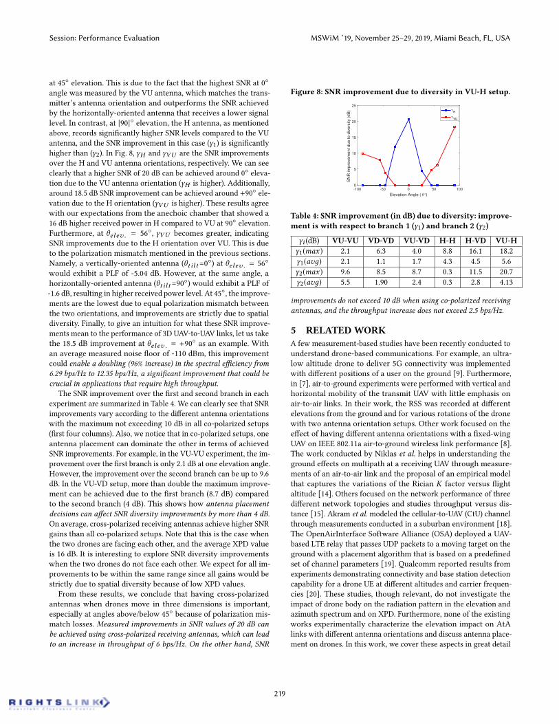
at 45 elevation. This is due to the fact that the highest SNR at 0angle was measured by the VU antenna, which matches the trans-mitter’s antenna orientation and outperforms the SNR achievedby the horizontally-oriented antenna that receives a lower signallevel. In contrast, at |90| elevation, the H antenna, as mentionedabove, records significantly higher SNR levels compared to the VUantenna, and the SNR improvement in this case (γ1) is significantlyhigher than (γ2). In Fig. 8, γH and γVU are the SNR improvementsover the H and VU antenna orientations, respectively. We can seeclearly that a higher SNR of 20 dB can be achieved around 0 eleva-tion due to the VU antenna orientation (γH is higher). Additionally,around 18.5 dB SNR improvement can be achieved around +90 ele-vation due to the H orientation (γVU is higher). These results agreewith our expectations from the anechoic chamber that showed a16 dB higher received power in H compared to VU at 90 elevation.Furthermore, at θelev . = 56, γVU becomes greater, indicatingSNR improvements due to the H orientation over VU. This is dueto the polarization mismatch mentioned in the previous sections.Namely, a vertically-oriented antenna (θt il t=0) at θelev . = 56would exhibit a PLF of -5.04 dB. However, at the same angle, ahorizontally-oriented antenna (θt il t=90) would exhibit a PLF of-1.6 dB, resulting in higher received power level. At 45, the improve-ments are the lowest due to equal polarization mismatch betweenthe two orientations, and improvements are strictly due to spatialdiversity. Finally, to give an intuition for what these SNR improve-ments mean to the performance of 3D UAV-to-UAV links, let us takethe 18.5 dB improvement at θelev . = +90 as an example. Withan average measured noise floor of -110 dBm, this improvementcould enable a doubling (96% increase) in the spectral efficiency from6.29 bps/Hz to 12.35 bps/Hz, a significant improvement that could becrucial in applications that require high throughput.
The SNR improvement over the first and second branch in eachexperiment are summarized in Table 4. We can clearly see that SNRimprovements vary according to the different antenna orientationswith the maximum not exceeding 10 dB in all co-polarized setups(first four columns). Also, we notice that in co-polarized setups, oneantenna placement can dominate the other in terms of achievedSNR improvements. For example, in the VU-VU experiment, the im-provement over the first branch is only 2.1 dB at one elevation angle.However, the improvement over the second branch can be up to 9.6dB. In the VU-VD setup, more than double the maximum improve-ment can be achieved due to the first branch (8.7 dB) comparedto the second branch (4 dB). This shows how antenna placementdecisions can affect SNR diversity improvements by more than 4 dB.On average, cross-polarized receiving antennas achieve higher SNRgains than all co-polarized setups. Note that this is the case whenthe two drones are facing each other, and the average XPD valueis 16 dB. It is interesting to explore SNR diversity improvementswhen the two drones do not face each other. We expect for all im-provements to be within the same range since all gains would bestrictly due to spatial diversity because of low XPD values.
From these results, we conclude that having cross-polarizedantennas when drones move in three dimensions is important,especially at angles above/below 45 because of polarization mis-match losses. Measured improvements in SNR values of 20 dB canbe achieved using cross-polarized receiving antennas, which can leadto an increase in throughput of 6 bps/Hz. On the other hand, SNR
Figure 8: SNR improvement due to diversity in VU-H setup.
-100 -50 0 50 100
Elevation Angle ( °)
0
5
10
15
20
25
SN
R im
pro
vem
ent due to d
ivers
ity (
dB
) H
VU
Table 4: SNR improvement (in dB) due to diversity: improve-ment is with respect to branch 1 (γ1) and branch 2 (γ2)
γi (dB) VU-VU VD-VD VU-VD H-H H-VD VU-Hγ1(max) 2.1 6.3 4.0 8.8 16.1 18.2γ1(avд) 2.1 1.1 1.7 4.3 4.5 5.6γ2(max) 9.6 8.5 8.7 0.3 11.5 20.7γ2(avд) 5.5 1.90 2.4 0.3 2.8 4.13
improvements do not exceed 10 dB when using co-polarized receivingantennas, and the throughput increase does not exceed 2.5 bps/Hz.
5 RELATEDWORKA few measurement-based studies have been recently conducted tounderstand drone-based communications. For example, an ultra-low altitude drone to deliver 5G connectivity was implementedwith different positions of a user on the ground [9]. Furthermore,in [7], air-to-ground experiments were performed with vertical andhorizontal mobility of the transmit UAV with little emphasis onair-to-air links. In their work, the RSS was recorded at differentelevations from the ground and for various rotations of the dronewith two antenna orientation setups. Other work focused on theeffect of having different antenna orientations with a fixed-wingUAV on IEEE 802.11a air-to-ground wireless link performance [8].The work conducted by Niklas et al. helps in understanding theground effects on multipath at a receiving UAV through measure-ments of an air-to-air link and the proposal of an empirical modelthat captures the variations of the Rician K factor versus flightaltitude [14]. Others focused on the network performance of threedifferent network topologies and studies throughput versus dis-tance [15]. Akram et al. modeled the cellular-to-UAV (CtU) channelthrough measurements conducted in a suburban environment [18].The OpenAirInterface Software Alliance (OSA) deployed a UAV-based LTE relay that passes UDP packets to a moving target on theground with a placement algorithm that is based on a predefinedset of channel parameters [19]. Qualcomm reported results fromexperiments demonstrating connectivity and base station detectioncapability for a drone UE at different altitudes and carrier frequen-cies [20]. These studies, though relevant, do not investigate theimpact of drone body on the radiation pattern in the elevation andazimuth spectrum and on XPD. Furthermore, none of the existingworks experimentally characterize the elevation impact on AtAlinks with different antenna orientations and discuss antenna place-ment on drones. In this work, we cover these aspects in great detail
Session: Performance Evaluation MSWiM ’19, November 25–29, 2019, Miami Beach, FL, USA
219

and provided valuable insight that can help simulating, modeling,and deploying drone-based networks.
6 CONCLUSIONIn this work, we presented results from experiments that mainlyinvestigate the effects of the drone body and elevation on the per-formance of polarized UAV-to-UAV links. First, we analyzed theimpact of relative direction and body obstruction on the RSS whentwo drones are in the same plane and showed that the average RSScan be reduced by up to 16 dB depending on the relative directionof the transmitter. Then, we investigated the impact of the dronebody on polarization mixing and XPD and found that the body ofthe drone can manipulate the polarization of the incoming wavesand reduce XPD by more than 20 dB compared to when the antennais isolated and not mounted on a drone; a result that can be cru-cial when modeling polarized UAV-based MIMO channels. Second,we proposed a model that includes these additional body-inducedlosses for more accurate results when predicting the large-scalefading behavior of air-to-air links with different relative movementsand directions in the azimuth plane. Third, we analyzed the impactof elevation angle on the RSS and the improvements due to diver-sity in a LOS UAV-to-UAV link for six different antenna orientationsetups. In doing so, we found that the overall performance in threedimensions with various antenna orientations is mainly driven bythe elevation angle. The RSS for the same antenna orientation canchange dramatically (by up to 30 dB) depending on the elevationangle of the receiving drone with respect to the transmitting drone.We also showed that a correlation coefficient less than 0.7 and rea-sonable diversity gains can be achieved with an antenna spacingof 2
3λ for both co-polarized and cross-polarized channels. We be-lieve that these results can affect drone-based antenna placementand selection algorithms, optimization models that target droneplacement, and future UAV-based channel models that currentlyfall short in capturing the discussed effects.
7 ACKNOWLEDGEMENTSThis work has been supported by the U.S. Department of HomelandSecurity (DHS), CounteringWeapons of Mass Destruction (CWMD)Office, under a competitively awarded grant No. 18DNARI00029-01-00. This support does not constitute an express or implied en-dorsement on the part of the Government. This work was alsosupported in part by the National Science Foundation under grantsCNS-1526269 and CNS-1823304.
REFERENCES[1] "Global Commercial Drones Market 2018-2022," in Business Wire, August 2018.[2] S. Baidya, Z. Shaikh, and M. Levorato, "FlyNetSim: An Open Source Synchronized
UAV Network Simulator based on ns-3 and Ardupilot," in Proc.of the 21st ACMIntern. Conference on Modeling, Analysis and Simulation of Wireless and MobileSystems (ACM MSWiM), 2018.
[3] A. Al-Hourani, S. Kandeepan, and S. Lardner, "Optimal LAP Altitude For MaximumCoverage," in Proc. of IEEE Letters on Wireless Communications, December 2014.
[4] E. Kalantari, M. Shakir, H. Yanikomeroglu, and A. Yongacoglu, "Backhaul-awareRobust 3D Drone Placement in 5G+ Wireless Networks," in Proc. IEEE Intern.Conference on Communications Workshops (ICC Workshops), July, 2017
[5] R. Ghanavi, E. Kalantari, M. Sabbaghian, H. Yanikomeroglu, and A. Yongacoglu"Efficient 3D aerial base station placement considering users mobility by reinforce-ment learning," in Proc. of IEEE WCNC, 2018.
[6] M. Mozaffari, W. Saad, M. Bennis, and M. Debbah, "Mobile Internet of Things:Can UAVs Provide an Energy-Efficient Mobile Architecture?," Proc. of IEEE Global
Communications Conference (GLOBECOM), 2016.[7] E. Yanmaz, R. Kuschnig, and C. Bettstetter, "Achieving air-ground communications
in 802.11 networks with three-dimensional aerial mobility," in Proc. of IEEE Intern.Conf. Comp. Commun. (INFOCOM), Mini conference,, April 2013.
[8] C.-M. Cheng, P.-H. Hsiao, H. Kung, and D. Vlah, "Performance measurement of802.11a wireless links from UAV to ground nodes with various antenna orienta-tions," in Proc. of Intl. Conf. Computer Comm. and Networks, October 2006.
[9] Philip A. Catherwood, Brendan Black, Ebrahim Bedeer, Adnan Ahmad Cheema,Joseph Rafferty, James A. D. McLaughlin,"Radio Channel Characterization of Mid-Band 5G Service Delivery for Ultra-LowAltitude Aerial Base Stations," IEEE Access7: 8283-8299, Jan. 2019.
[10] E. Yanmaz, R. Kuschnig, and C. Bettstetter, "Channel measurements over 802.11a-based UAV-to-ground links," in Proc. Intern. Workshop on Wireless Networkingfor Unmanned Autonomous Vehicles, 2011.
[11] T. Willink, C. Squires, G. Colman, and M. Muccio, "Measurement and characteri-zation of low altitude air-to-ground MIMO channels," IEEE Trans. Veh. Technol.,vol. 65, no. 4, Apr. 2016
[12] Y. Shi, R. Enami, J. Wensowitch, and J. Camp, "UABeam: UAV-Based BeamformingSystem Analysis with In-Field Air-to-Ground Channels," Proc. of 15th Annual IEEEIntern. Conference on Sensing, Communication, and Networking (SECON), 2018.
[13] J. Chen, B. Daneshrad, and W. Zhu, "MIMO performance evaluation for airbornewireless communication systems," in Proc. IEEE MILCOM, 2011.
[14] N. Goddemeier and C. Wietfeld, "Investigation of Air-to-Air Channel Charac-teristics and a UAV Specific Extension to the Rice Model," Proc. of IEEE GlobecomWorkshops (GC Wkshps), 2015.
[15] E. Yanmaz, S. Hayat, J. Scherer, and C. Bettstetter, "Experimental PerformanceAnalysis of Two-Hop Aerial 802.11 Networks," in Proc. of IEEE WCNC, 2014.
[16] D. Tse and P. Viswanath, "Fundamentals of Wireless Communication," CambridgeUniversity Press, 2005.
[17] W. Stutzman and G. Thiele, "Antenna Theory and Design," 3rd Ed. Wiley, 2013.[18] A. Al-Hourani and K. Gomez, "Modeling Cellular-to-UAV Path-Loss for Suburban
Environments," in IEEE Wireless Communications Letters, vol. 7, no.1, Feb. 2018.[19] R. Gangula, O. Esrafilian, D. Gesbert, C. Roux, F. Kaltenberger, and R. Knopp,
"Flying Rebots: First Results on an Autonomous UAV-Based LTE Relay UsingOpen Airinterface," Proc. of IEEE 19th International Workshop on Signal ProcessingAdvances in Wireless Communications (SPAWC), June 2018.
[20] "LTE Unmanned Aircraft Systems: Trial Report," Qualcomm, May 2017.[21] R. Vaughan, "Polarization Diversity in Mobile Communications," IEEE Transac-
tions on Vehicular Technology, Vol. 39, No. 3, August 1990, pp. 177-186[22] R. G. Vaughan and J. B. Andersen, "Antenna diversity in mobile communications,"
IEEE Trans. Veh. Technol., vol. VT-36, Nov. 1987.[23] V. Rodriguez, "Basic Rules for Indoor Anechoic Chamber Design [Measurements
Corner]," IEEE Antennas Propagat. Mag., Vol. 58, No. 6, Dec. 2016[24] S.-C. Kwon and G. L. St Âĺuber, "Geometrical theory of channel depolarization,"
IEEE Trans. Veh. Technol., vol. 60, Oct. 2011[25] M. Shafi, M. Zhang, A. Moustakas, P. Smith, A. Molisch, F. Tufvesson, and S.
Simon, "Polarized MIMO channels in 3-D: models, measurements and mutualinformation," IEEE J. Select. Areas Commun., vol. 24, no. 3, Mar. 2006
[26] "Spatial channel model for multiple input multiple output MIMO simulations,"3GPP, vol. TR 25.996, v6.1.0, Sep. 2003
[27] J. Wang, J. Zhao, and X. Gao, "Modeling and analysis of polarized MIMO channelsin 3D propagation environment," in PIMRC, 2010.
[28] X. Su, D. Choi, X. Liu, and B Peng, "Channel Model for Polarized MIMO SystemsWith Power Radiation Pattern Concern," IEEE Access, vol. 4, Mar. 2016
[29] M.-T. Dao, V.-A. Nguyen, Y.-T. Im, S.-O. Park, and G. Yoon, "3D polarized channelmodeling and performance comparison of MIMO antenna configurations withdifferent polarizations," IEEE Trans. Antennas Propag., vol. 59, no. 7, 2011.
[30] L. Zeng, X. Cheng, C.-X. Wang, and X. Yin, "A 3D geometry-based stochasticchannel model for UAV-MIMO channels," in Proc. IEEE WCNC, Mar. 2017.
[31] H. Jiang, Z. Zhang, L. Wu, and J. Dang, "Three-dimensional geometry based UAV-MIMO channel modeling for A2G communication environments," IEEE Commun.Lett., vol. 22, no. 7, Jul. 2018.
[32] Y. Xing, O. Kanhere, S. Ju, T. S. Rappaport, and G. R. MacCartney Jr., "Verificationand calibration of antenna cross-polarization discrimination and penetrationloss for millimeter wave communications," 2018 IEEE 88th Vehicular TechnologyConference (VTC2018-Fall), Chicago, USA, Aug. 2018.
[33] Y.-G. Lim, Y. J. Cho, T. Oh, Y. Lee, and C.-B. Chae, "Relationship between cross-polarization discrimination (XPD) and spatial correlation in indoor small-cellMIMO systems," IEEE Wireless Commun. Lett., vol. 7, no. 4, Aug. 2018
[34] Y. Yao, J. Zheng, and Z. Feng,"Diversity measurements for on-body channelsusing a tri-polarization antenna at 2.45 GHz", IEEE Antennas Wirel. Propag. Lett.,2012.
[35] T. Neubauer and P. C. F. Eggers, "Simultaneous characterization of polarizationmatrix components in pico cells," in Proc. Veh. Technol. Conf., 1999.
[36] P. Chandhar, D. Danev, and E. G. Larsson, "Massive MIMO for communicationswith drone swarms," IEEE Transactions on Wireless Communications, vol. 17, no.3, March 2018.
Session: Performance Evaluation MSWiM ’19, November 25–29, 2019, Miami Beach, FL, USA
220