EXPERIMENTAL DETERMINATION OF PORO-ELASTIC PROPERTIES OF MATERIALS …€¦ · ·...
8
1 15 th International Congress on Sound and Vibration 6-10 July 2008, Daejeon, Korea EXPERIMENTAL DETERMINATION OF PORO-ELASTIC PROPERTIES OF MATERIALS COMMONLY USED FOR NOISE AND VIBRATION CONTROL G.Amadasi 1 A.Cerniglia 2 and B.Duperray 3 1 SCS Euroacoustic/01dB Solution, Avigliana, Italy, [email protected] 2 SCS Euroacoustic, Avigliana, Italy, [email protected] 3 01dB Metravib, Limonest, France, [email protected] Abstract In our modern world almost everything is designed through simulation, as the power of computers allows implementing extremely advanced simulation modeling: even Sound and Vibration characteristics of a “project” are very well simulated giving reliable results in very short time. However, computer simulation need data input, and among them are the material characteristics for Sound and Vibration simulation. It is clear that even the best simulation models cannot overcome the fact of “rubbish in = rubbish out” Materials are a fundamental resources and their utilization derives from exploiting the properties and processing capabilities as well as functionality. But engineers continuously design new materials, with new properties and capabilities for a specific function and at lower cost. A common and updated public data-base of material properties, and more specifically for poro-elastic properties for Noise control applications, does not exist and each parameter shall be measured with an independent method and with different equipment, facing the problem of data format and consistency in the Data base construction. A single and unique system has been developed in an integrated environment, capable of performing all necessary measurements and fill in the Database. Nowadays a good design simulation must be based on the knowledge of material characteristics. 1. INTRODUCTION Poro-Elastic properties of materials for Noise and Vibration Control applications, are normally defined within 3 main categories of materials applications: Sound Absorption, Sound Insulation and Vibration damping; those yield to measure 3 ensemble characteristics: Elastic characteristics, Impedance and porosity aspects. From the characteristic of machines structure, to porous materials for Noise and Vibration control (foams or textile), elastic and damping properties have to be determined. More specific parameters are Young’s and shear moduli, Poisson’s ratios and structural damping coefficients in quasistatic and dynamic (resonant) conditions. Impedance is an important parameter for Sound and Vibration applications, even if some more specific ones are more commonly used, it is related to the possibility to “transport” the Sound
Transcript of EXPERIMENTAL DETERMINATION OF PORO-ELASTIC PROPERTIES OF MATERIALS …€¦ · ·...

1
15th International Congress on Sound and Vibration6-10 July 2008, Daejeon, Korea
EXPERIMENTAL DETERMINATION OF PORO-ELASTIC PROPERTIES OF MATERIALS
COMMONLY USED FOR NOISE AND VIBRATION CONTROL
G.Amadasi1 A.Cerniglia2 and B.Duperray3
1SCS Euroacoustic/01dB Solution, Avigliana, Italy, [email protected] 2SCS Euroacoustic, Avigliana, Italy, [email protected]
301dB Metravib, Limonest, France, [email protected]
Abstract In our modern world almost everything is designed through simulation, as the power of computers allows implementing extremely advanced simulation modeling: even Sound and Vibration characteristics of a “project” are very well simulated giving reliable results in very short time. However, computer simulation need data input, and among them are the material characteristics for Sound and Vibration simulation. It is clear that even the best simulation models cannot overcome the fact of “rubbish in = rubbish out” Materials are a fundamental resources and their utilization derives from exploiting the properties and processing capabilities as well as functionality. But engineers continuously design new materials, with new properties and capabilities for a specific function and at lower cost. A common and updated public data-base of material properties, and more specifically for poro-elastic properties for Noise control applications, does not exist and each parameter shall be measured with an independent method and with different equipment, facing the problem of data format and consistency in the Data base construction. A single and unique system has been developed in an integrated environment, capable of performing all necessary measurements and fill in the Database. Nowadays a good design simulation must be based on the knowledge of material characteristics.
1. INTRODUCTION
Poro-Elastic properties of materials for Noise and Vibration Control applications, are normally defined within 3 main categories of materials applications: Sound Absorption, Sound Insulation and Vibration damping; those yield to measure 3 ensemble characteristics: Elastic characteristics, Impedance and porosity aspects. From the characteristic of machines structure, to porous materials for Noise and Vibration control (foams or textile), elastic and damping properties have to be determined. More specific parameters are Young’s and shear moduli, Poisson’s ratios and structural damping coefficients in quasistatic and dynamic (resonant) conditions. Impedance is an important parameter for Sound and Vibration applications, even if some more specific ones are more commonly used, it is related to the possibility to “transport” the Sound

ICSV15 • 6-10 July 2008 • Daejeon • Korea
2
energy, while Sound Energy represent the energy stored in a travelling wave. Specific Impedance in a point is the ratio of Complex Amplitudes of Sound Pressure P to Particle Velocity u , and the phase relationship between P and u is the same we have between voltage and current in an electrical circuit. Determining Impedance requires a well defined measurement conditions like in the Kundt tube apparatus, in which we will have plane waves hitting a materials (direct waves), and reflected plane waves; measuring the direct and reflected energy yield to the Sound Absorption coefficient and Impedance on the material surface. Porosity express the relationship of volume occupied by fluid and by solid component and it is also in relationship with density of the air inside the pores, density of the porous and density of the material composing the skeleton. Porosity can be derived from the Flow Resistivity, quantifing the permeability of the material to the passage of the air through it: this is a sort index of the viscous dissipation potential of the material. The ensemble of Porous material parameters necessary to characterize their behaviour relay on different physical models from Bolton, Allard, Johnson, Delany-Bazley, Biot and some others. Some of these parameters are relatively simple to measure (i.e. density and flow resistance) while others are more complicated (i.e. tortousity, viscous and thermal lenghts). An additional difficulty is that some porous materials are composed by two phases: the solid phase is the frame (called also skeleton) and the fluid phase is the air inside the pores. The dynamical behaviour is very complex and is related not only to the fluid and solid phase separately but also to the interaction between them. Among the different physical models proposed we can distinguish two main cathegories:
• simplified models where only few parameters allows to characterize the material • complete models where almost all parameters are required to characterize the behaviour
It cannot be possible to give a general rule to choose one model instead of another one, the choice is more a kind of compromise between the informations really available, the kind of material, the role of the porous materials in the Noise control package and the acoustic quantity we are loking for. For example Delany-Bazley model take in consideration mainly the flow resistance and it can be a good choice to determine absorption of a porous layer rigidly or free backed, but on the other hand this model is not good at all when the porous material is in the midlle of an acoustic barrier as the frame elasticity is not taken into account; it becomes critical when the stifness of the skeleton is similar to the bulk modulus of the fluid. Some other models are more suitable for porous having opened or semi-opened cells (like foams) whereas others are good for porous fibrous having synthetic or natural or mineral fibers (like poorus textile, glass wool, ..). Below there is a table of properties of porous materials and corresponding physical models.

ICSV15 • 6-10 July 2008 • Daejeon • Korea
3
2. POROUS MATERIALS INTRINSIC PROPERTIES, DEFINITIONS AND EXPERIMENTAL DEVICES
Porosity is a dimensionless parameter, simply espress the ratio between the volume of the air inside the pores and total volume (i.e. the volume of the mixture where "mixture" means skeleton plus air inside the skeleton):
The porosity ranges from 0.6÷ 0.7 for high density material (highly pressed textile fibrous) to 0.9÷ 0.98 for low density material (foam or soft and limp fibrous). Porosity can be deduced by the previous relationship when mixture and frame material’s density are known or measured by a device based on Boyle’s law (for ideal gas) Flow resistivity is a physical quantity directly obtained by measurement of the Flow resistance (often indicated with "R" in bibliography) defined as: where ∆p is the drop of pressure (expressed in Pascal) due to the sample presence and v is the airflow speed (in m/s). the flow resistance is expressed in Pa/(ms-1) = Nm-3s often indicated as "rayls" (1 rayls = 1 Nm-3s). The Flow resisitivity R1 is derived from the flow resistance dividing by the sample’s thickness (t) its unit of measure is Pa/(m2s) or Nm-4s or rayls/m. The SCS 9023 is a device to measure the flow resistance system and is composed of a 100mm diameter cylinder, holding a low frequency pressure wave source, a low frequency response ½” microphone and an adjustable sample holder, according to UNI EN 29053. The low frequency pressure wave in generated by means of a piston, which alternating displacement is driven by a 10:1 geared motor and an electronic, closed loop speed controller. Further to the standard reference flow speed, three different flow speeds may be generated by simply substituting one-of-four calibrated cam on the geared motor shaft.
Frame Young modulus, Loss factor, Poisson coefficient and Bulk Modulus in vacuum (sometimes indicated as E, ν, η and K ) allow to quantify the elastic behaviour of the solid phase of the porous material. Basically they must be determined in vacuum condition otherwise the dynamic of the frame is affected by the elasticity the air inside the pores with react with its bulk modulus and loss factor.

ICSV15 • 6-10 July 2008 • Daejeon • Korea
4
Several devices are available to measure mechanical impedance of the porous material considering it always acting like a pure spring. The elasticity of the frame (generally expressed in Pascal units) plays an important role especially when the porous material is an intermediate layer in a double wall barrier system, or when frame’s Young modulus has a value not far away from the fluid bulk modulus. This last happens generally with low density (10÷ 100 kg/m3) foam and fibrous. It is well known that real Young modulus and loss factor can be combined into a complex Young modulus E where the imaginary part expresses the dissipative term. This parameter is frequency dependent and is called dynamic complex Young modulus, even that a quasi-static or static value is generally used. However, the elasticity of a porous material is strictly related to the elastic property of the skeleton’s constituent material and to the porosity with affect the porous stiffness. For this reason is generally a good practice to produce the curve of the Young modulus versus the porous density. The SCS 9026 device allows to measure several quantities both in quasi static and dynamic conditions, the later also in vacuum. To determine frame K (Bulk Modulus) is necessary a dynamic experiment in which the sample of porous material is placed between an electrodynamic shaker and a rigid structure at the top or, alternatively, a free suspended mass. Measuring the transfer function between the displacement of the lower plate and the force resulting to the upper plate (rigid case) yield to dynamic E, from which we can derive K (bulk modulus) out of a set of test on sample of the same materials but with different geometry. Theory applied is from Lindley for cylinder geometry rigidly connected to both ends, in which the Compressibillity modules G is calculated from experimental results for at least 2 different geometries (ratio of samples diameter to samples length). From the 2 measurements it is possible to calculate G and ν and then K, as the solution of a 2-linear equations system in G and ν using Newton-Raphson method. DMA+450 is dedicated to the accurate analysis of the viscoelastic properties of advanced polymer based materials: thermoplastic polymers, thermosetting polymers, rubbers, etc… Based on the principle of a forced sinusoidal excitation , out of resonance, of a specimen of material, the DMA+450 allows to measure accurately the Young Modulus, (E*) the Shear Modulus (G*) of solids materials, as well as the dynamic viscosity of pastes and high viscosity liquids. By controlling separately both dynamic and static setting values applied to the specimen, DMA+450 allows to perform as well pure dynamic tests, combined static/dynamic tests, and as well pure static tests as creep tests, strain relaxation, compression or tension tests. A dedicated thermal chamber makes possible analysis over a wide temperature range from -150°C up to 450°C. Using a large range of specimen holders, DMA+450 allows tests on a large variety of specimen geometries and natures, for bending, shear, tension, and compression tests. DMA+450 allows determining the glass transition temperature, secondary transitions, frequency dependence (from 10E-5 Hz up to 1000 Hz), non linear behaviour (Mullis effect,

ICSV15 • 6-10 July 2008 • Daejeon • Korea
5
Payne effect), and as well curing follow up analysis in order to optimize curing process according to raw materials rheological characteristics. Specific calculations are included in the software to predict long term creep behaviour or viscoelastic characteristics beyond the experimental analysis range. The High sensibility of DMA+450 makes it very suitable for :
• Selection of materials • Determination of industrial products performances • Prediction of industrial products performances (by modelization from
viscoelastic properties) • Optimization of manufacturing process: Curing cycle, gel time, viscosity
profile, post-curing effects • Polymers’ formulation optimization: Fillers orientation, Polymers
compatibility, Selection of additives… • Durability of materials: ageing, fatigue, creep, prediction of long term
performances evolutions, conditioning effects… VHF 104 is an innovative Dynamic Mechanical Analyzer that offers a direct experimental method to measure the materials' viscoelastic properties (E*, G*)over a very high frequencies range from 100 Hz up to 10 kHz. Such a test requires only a few minutes, while traditional approach using DMA low frequency test on several temperature stages, requires a few hours test and a calculation through WLF law.
Temperature controlled tests may as well be achieved in the range from -50°C up to 110°C. VHF 104 allows optimizing the laboratory's productivity in meeting the requirements of industrials who wish to rapidly analyze large number of formulations of materials. Fluid in pore Bulk modulus Ka is the compression modulus of the air inside the pores. It could be considered as the compression Young modulus of the gas. The nominal value of the bulk modulus is: B = ρ c2 where ρ is the density of the gas (about 1.225 kg/m3 for air at room temperature) and c is the gas sound speed (about 340 m/s at room temperature). It results that the bulk modulus Ka is about 141610 Pascal. Neverthless the fluid bulk modulus of the air is related to the thermal condition at which there is interaction between the fluid and the frame. These conditions can vary from isothermal to adiabatic corresponding so that the fluid bulk modulus ranges from 1.02E+5 to 1.46E+5 Pascal. Generally isothermal conditions happen at low frequency when there is sufficent time for heat exchange between pore’s air and surrounding frame, on the opposite at high frequency there is not enough time for the heat exchange and the process is adiabatic. Concerning the fluid loss factor it can be said that it plays an important role at the resonance frequencies of a trim reducing the amplitude of the dynamic response. For free air the loss factor is very low but for air constrained into a pore becomes higher due to viscous coupling between solid and fluid phases. An indicative value suggested for the simulation is about 10%. For determining Loss factor η there are two accelerometers, located respectively at the shaker plate and at the top plate; the resonance of the system and the structural damping (obtained as ∆F/F with the 3 dB below peak method) are known. Then, being the top plate mass known, the stiffness of the spring is obtained and finally on the base of the geometry sample the Young modulus is derived. Young’s modulus is often used as a reference in order to classify the porous material into three main categories: limp, elastic or rigid, by comparing frame modulus "E" to that one of the air (indicated as "B" and ranging from 1.02E5 to 1.46E5 Pa) so that the porous is considered as:
ICSV15 • 6-10 July 2008 • Daejeon • Korea
6
• Limp when E < B • Elastic when E ≈ B • Rigid when E > B
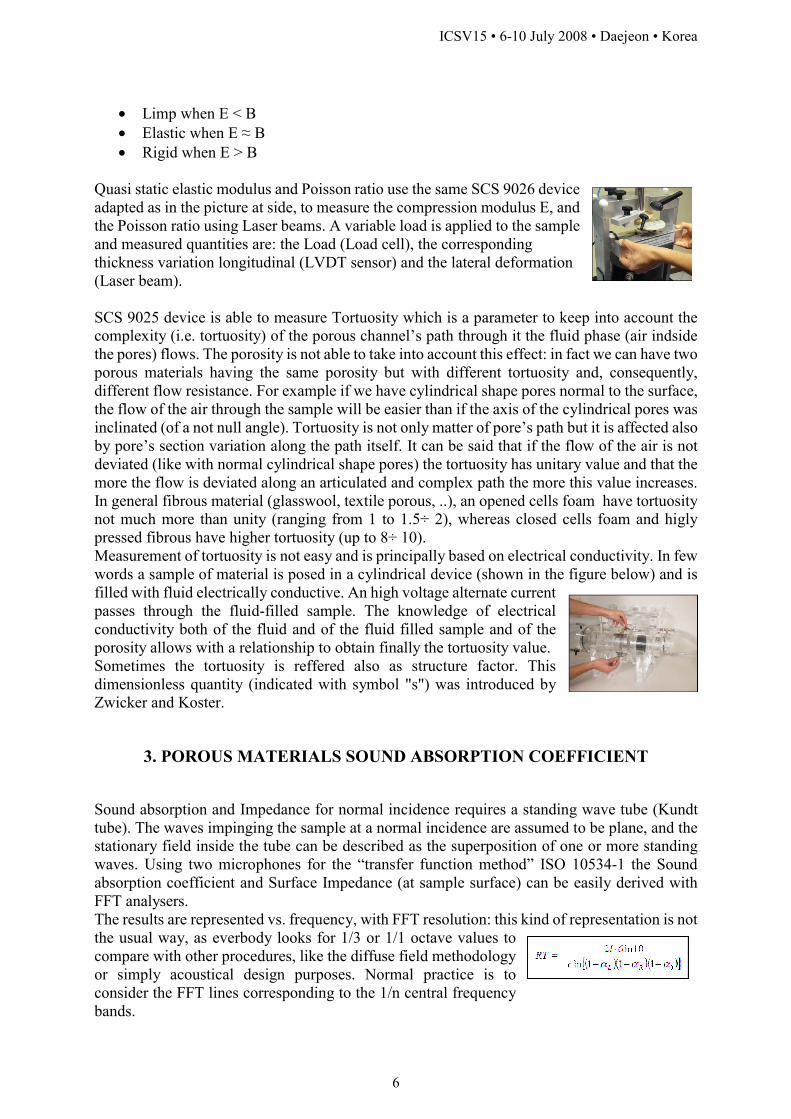
Quasi static elastic modulus and Poisson ratio use the same SCS 9026 device adapted as in the picture at side, to measure the compression modulus E, and the Poisson ratio using Laser beams. A variable load is applied to the sample and measured quantities are: the Load (Load cell), the corresponding thickness variation longitudinal (LVDT sensor) and the lateral deformation (Laser beam). SCS 9025 device is able to measure Tortuosity which is a parameter to keep into account the complexity (i.e. tortuosity) of the porous channel’s path through it the fluid phase (air indside the pores) flows. The porosity is not able to take into account this effect: in fact we can have two porous materials having the same porosity but with different tortuosity and, consequently, different flow resistance. For example if we have cylindrical shape pores normal to the surface, the flow of the air through the sample will be easier than if the axis of the cylindrical pores was inclinated (of a not null angle). Tortuosity is not only matter of pore’s path but it is affected also by pore’s section variation along the path itself. It can be said that if the flow of the air is not deviated (like with normal cylindrical shape pores) the tortuosity has unitary value and that the more the flow is deviated along an articulated and complex path the more this value increases. In general fibrous material (glasswool, textile porous, ..), an opened cells foam have tortuosity not much more than unity (ranging from 1 to 1.5÷ 2), whereas closed cells foam and higly pressed fibrous have higher tortuosity (up to 8÷ 10). Measurement of tortuosity is not easy and is principally based on electrical conductivity. In few words a sample of material is posed in a cylindrical device (shown in the figure below) and is filled with fluid electrically conductive. An high voltage alternate current passes through the fluid-filled sample. The knowledge of electrical conductivity both of the fluid and of the fluid filled sample and of the porosity allows with a relationship to obtain finally the tortuosity value. Sometimes the tortuosity is reffered also as structure factor. This dimensionless quantity (indicated with symbol "s") was introduced by Zwicker and Koster.
3. POROUS MATERIALS SOUND ABSORPTION COEFFICIENT
Sound absorption and Impedance for normal incidence requires a standing wave tube (Kundt tube). The waves impinging the sample at a normal incidence are assumed to be plane, and the stationary field inside the tube can be described as the superposition of one or more standing waves. Using two microphones for the “transfer function method” ISO 10534-1 the Sound absorption coefficient and Surface Impedance (at sample surface) can be easily derived with FFT analysers. The results are represented vs. frequency, with FFT resolution: this kind of representation is not the usual way, as everbody looks for 1/3 or 1/1 octave values to compare with other procedures, like the diffuse field methodology or simply acoustical design purposes. Normal practice is to consider the FFT lines corresponding to the 1/n central frequency bands.

ICSV15 • 6-10 July 2008 • Daejeon • Korea
7
Sound absorption coefficient and Surface Impedance of a test sample can also be derived by a method based on the measurement of the reverberation time inside the tube. In fact the transient properties of the sound field in a closed tube show that the succession of wave fronts obeys a simple exponential rule so that the impact of the sound absorption of the termination can be predicted analytically. Though a similar procedure outlined by Beranek, a new apparatus has been recently developed with a different processing. The sound is injected in the tube by a hole on the side and the RT is measured using Impulse Response. The expression derived for RT includes α0 as the Sound Absorption coefficient for the tube without any materials, and αL and αR for Sound Absorption coefficient of materials placed to the Left and Right ends respectively. “l” is the total tube length, c the speed of sound. From the above RT expression the following expressines applies. For an empty tube (rigid termination ends) is: and For one sample to the Right end: and
For samples at both ends: Clearly, from the measurement of reverberation time in the tube, it is not possible to derive separately the two unknowns αL and αR and it is necessry to define the equivalent absorption coefficient α* in which it is artificially set α*= αL = αR thus gives an absorption equivalent to that produced by two terminations of the same type giving the same reverberation time in the tube. It can be demonstrated that, by applying the Millington-Sette formulation for reverberation time, the equivalent reflection coefficient r* is given by the geometric average of the single reflection coefficients and Sound absorption coefficient becomes: The sound absorption α* can be regarded an expected value from a simple theory which basically combines the separated coefficients taken as inputs. The “Acoustic Material Properties Measurement System SCS9020B – Kundt/T60/TL Tubes”, is a complete set of hardware and software tools, for measuring porous acoustic material properties as Acoustic Absorption, standard Impedance, characteristic Impedance Zc, Gamma function, Transmission Loss function. The sound absorption measurement is related to the capacity of materials to absorb, reflect and dissipate acoustic energy; SCS9020B – Kundt/T60/TL tubes allow accurate soft and porous material properties measurement, based on this assumption. Depending on the specific system arrangement, the user can perform many measurement of different porous acoustic properties on the same material sample. The system has been conceived in a modular way, thus minimizing the total number of physical tube pieces: in fact only 7 cylindrical elements are needed to arrange three different measuring systems.
1 “Kundt tubes” configuration represents the basic, standard system setup for Acoustic

ICSV15 • 6-10 July 2008 • Daejeon • Korea
8
absorption coefficient and Impedance measurements (2 microphones - transfer function method), according to ISO 10534-2 and ASTM E1050-98.
2 “T60 tubes” configuration represents a novel method for absorption coefficient measurements of one or two material samples (even different) at a time, based on the reverberation time measurements inside the tube setup (1 microphone). This original method has been introduced and developed by researchers of University of Ferrara – Italy.
3 “TL tubes” configuration represents the third tube arrangement scheme, which allows Transmission Loss measurements (2, 3 or 4 microphones method).
A complete series of porous material testing for poro-elastic properties is available under the name of SCS-902A Material Testing suite
References [1] J.-F. Allard, “Propagation of sound in porous media. Modelling sound absorbing materials”, Elsevier, 1993. [2] M. Devergea and L. Jaouenb, “A review of experimental methods for the elastic and damping characterizations of acoustical porous materials” [3] Leo L. Beranek, "Noise and vibration control" Revised Edition – INCE (Institute of Noise Control Engineering) [4] EN ISO 10534-1: 2001 “Acoustics – Determination of sound absorption coefficient and impedance in impedances tube – Part 1: Method using standing wave ratio” [5] EN ISO 10534-2: 2001 “Acoustics – Determination of sound absorption coefficient and impedance in impedances tube – Part 2: Transfer – function method” [6] ISO 354: 1985 “Acoustics – Measurement of sound absorption in a reverberation room”. [7] M. Schröeder, “New method of measuring reverberation time”, J. Acoust. Soc. Am., 37, 409-412 (1965). [8] L. E. Kinsler et al., “Fundamentals of Acoustics”, Third Edition, John Wiley & Sons (1982). [9] H. Kuttruff, “Room Acoustics” Fourth edition, Spoon Press, London (2000).