Experimental and Analytical Study on Reinforced Concrete...
11
Send Orders for Reprints to [email protected] The Open Construction and Building Technology Journal, 2014, 8, 153-163 153 1874-8368/14 2014 Bentham Open Open Access Experimental and Analytical Study on Reinforced Concrete Beams in Bending Strengthened with FRP C.C. Spyrakos 1,* , I.G. Raftoyiannis 1 , L. Credali 2 and J. Ussia 2 1 Civil Engng Dept., National Technical University of Athens, Greece; 2 Ardea e Sistemi S.r.l., Bolonia, Spain Abstract: The performance of the interface between fiber reinforced polymer (FRP) composites and concrete is one of the key factors affecting the behavior of strengthened reinforced concrete (RC) structures. Existing laboratory research has shown that RC beams strengthened with FRP sheets usually fail because of either debonding of the impregnated fabric from the concrete substrate or fracture of the FRP. This work presents an experimental and analytical investigation of the effectiveness of FRP strengthening sheets on RC beams aiming at increasing their flexural strength and stiffness. Experi- mental results obtained from beam specimens tested under four-point bending are examined with main parameters being the resin type and the anchoring system. In addition, the procedure suggested by the EC8 - Greek Assessment & Retrofit- ting Code (EC8-GARC) provisions is applied and compared with the experimental results. Keywords: Anchoring systems, assessment of FRP design codes, concrete beam testing, FRP debonding, FRP failure modes, FRP strengthening. 1. INTRODUCTION External bonding of FRP composites constitutes a popular technique to strengthen concrete structures worldwide. Two types of debonding failure are commonly observed in strengthened RC members: sheet-end and intermediate crack induced debonding. In order to understand and develop meth- ods to predict such debonding failures, the bond behavior between concrete and FRP has been widely studied using simple shear tests on FRP plate/sheet-to-concrete bonded joints and a great deal of research results is now available However, for intermediate crack induced debonding failures, the debonding behavior can significantly differ from that ob- served in a simple shear test. Among other factors, the most significant difference may be the fact that between two adja- cent cracks the FRP is subjected to tension at both cracks. Teng et al. [1] presented an analytical model for the debonding process of an FRP-to-concrete bonded joint model where the FRP is subject to tension at both ends. Subramaniam et al. [2] studied the influence of the width of FRP sheets on the load-carrying capacity of RC beams for shear debonding. Chen and Qiao [3] presented a cohesive interface modeling approach for debonding analysis of adhe- sively bonded interface between two adjacent flexural cracks in concrete beams strengthened with externally bonded FRP plates. Chen et al. [4] presented a simplified analytical solu- tion for the debonding failure along a softening FRP-to- concrete interface between two adjacent cracks in concrete members. Gunes et al. [5] studied, experimentally and ana- lytically, debonding failures of FRP strengthened RC beams. Ombres [6] studied the debonding failure modes on FRP- strengthened RC beams using a nonlinear local deformation model derived from crack analysis based on slip and bond *Address correspondence to this author at the Civil Engng Dept., National Technical University of Athens, Greece; Tel: 00302107721180; Fax: 00302107721182; E-mail: [email protected] stresses. Benzarti et al. [7] presented a damage model to pre- dict the durability of bonded assemblies and particularly the debonding behavior of FRP strengthened concrete members. Ceroni et al. [8] presented a brief overview of anchorage systems by introducing experimental tests on several types of end-fixing for reinforced polymers (FRP) sheets glued on RC elements. Bruno et al. [9] proposed a refined model able to analyze edge-mixed-mode debonding problems of beams strengthened with externally bonded composite laminated plates, where the structural system consisted of a base beam, an adhesive layer and a bonded FRP plate. Casas and Pas- cual [10] presented a simplified model and an experimental validation for debonding of FRP strengthend RC beams in bending. Beams under four-point bending tested by Alagusunda- ramoorthy et al. [11] failed because of reinforcement yield- ing in tension before the concrete compression strain reached the limit of 0.3%. Bending cracks in the area between the two concentrated loads were observed in all beams tested – either prior or after strengthening. The majority of beams strengthened with CFRP sheets failed because of concrete compression at one of the concentrated loading positions. Upon the beginning of concrete compression, separation of FRP sheets was also observed. The RC beams tested by Takeda et al. [12] developed bending cracks and finally failed in compression of concrete. The strengthened beams also developed bending cracks, but failed in rupture of the carbon FRP sheets. Takeda et al. [12] concluded that by increasing the number of FRP sheets the flexural stiffness and strength increased, while the strain capacity decreased. The beam that was already loaded before being strengthened, after comparing it to a similar one strengthened with identical carbon FRP, a similar behavior was observed. Thus, it was concluded that the effect of initial loading on the flexural behavior of strengthened beams is negligible.
Transcript of Experimental and Analytical Study on Reinforced Concrete...

Send Orders for Reprints to [email protected]
The Open Construction and Building Technology Journal, 2014, 8, 153-163 153
1874-8368/14 2014 Bentham Open
Open Access
Experimental and Analytical Study on Reinforced Concrete Beams in Bending Strengthened with FRP
C.C. Spyrakos1,*
, I.G. Raftoyiannis1, L. Credali
2 and J. Ussia
2
1Civil Engng Dept., National Technical University of Athens, Greece;
2Ardea e Sistemi S.r.l., Bolonia, Spain
Abstract: The performance of the interface between fiber reinforced polymer (FRP) composites and concrete is one of the
key factors affecting the behavior of strengthened reinforced concrete (RC) structures. Existing laboratory research has
shown that RC beams strengthened with FRP sheets usually fail because of either debonding of the impregnated fabric
from the concrete substrate or fracture of the FRP. This work presents an experimental and analytical investigation of the
effectiveness of FRP strengthening sheets on RC beams aiming at increasing their flexural strength and stiffness. Experi-
mental results obtained from beam specimens tested under four-point bending are examined with main parameters being
the resin type and the anchoring system. In addition, the procedure suggested by the EC8 - Greek Assessment & Retrofit-
ting Code (EC8-GARC) provisions is applied and compared with the experimental results.
Keywords: Anchoring systems, assessment of FRP design codes, concrete beam testing, FRP debonding, FRP failure modes, FRP strengthening.
1. INTRODUCTION
External bonding of FRP composites constitutes a popular technique to strengthen concrete structures worldwide. Two types of debonding failure are commonly observed in strengthened RC members: sheet-end and intermediate crack induced debonding. In order to understand and develop meth-ods to predict such debonding failures, the bond behavior between concrete and FRP has been widely studied using simple shear tests on FRP plate/sheet-to-concrete bonded joints and a great deal of research results is now available However, for intermediate crack induced debonding failures, the debonding behavior can significantly differ from that ob-served in a simple shear test. Among other factors, the most significant difference may be the fact that between two adja-cent cracks the FRP is subjected to tension at both cracks.
Teng et al. [1] presented an analytical model for the debonding process of an FRP-to-concrete bonded joint model where the FRP is subject to tension at both ends. Subramaniam et al. [2] studied the influence of the width of FRP sheets on the load-carrying capacity of RC beams for shear debonding. Chen and Qiao [3] presented a cohesive interface modeling approach for debonding analysis of adhe-sively bonded interface between two adjacent flexural cracks in concrete beams strengthened with externally bonded FRP plates. Chen et al. [4] presented a simplified analytical solu-tion for the debonding failure along a softening FRP-to-concrete interface between two adjacent cracks in concrete members. Gunes et al. [5] studied, experimentally and ana-lytically, debonding failures of FRP strengthened RC beams. Ombres [6] studied the debonding failure modes on FRP-strengthened RC beams using a nonlinear local deformation model derived from crack analysis based on slip and bond
*Address correspondence to this author at the Civil Engng Dept., National
Technical University of Athens, Greece; Tel: 00302107721180;
Fax: 00302107721182; E-mail: [email protected]
stresses. Benzarti et al. [7] presented a damage model to pre-dict the durability of bonded assemblies and particularly the debonding behavior of FRP strengthened concrete members. Ceroni et al. [8] presented a brief overview of anchorage systems by introducing experimental tests on several types of end-fixing for reinforced polymers (FRP) sheets glued on RC elements. Bruno et al. [9] proposed a refined model able to analyze edge-mixed-mode debonding problems of beams strengthened with externally bonded composite laminated plates, where the structural system consisted of a base beam, an adhesive layer and a bonded FRP plate. Casas and Pas-cual [10] presented a simplified model and an experimental validation for debonding of FRP strengthend RC beams in bending.
Beams under four-point bending tested by Alagusunda-ramoorthy et al. [11] failed because of reinforcement yield-ing in tension before the concrete compression strain reached the limit of 0.3%. Bending cracks in the area between the two concentrated loads were observed in all beams tested – either prior or after strengthening. The majority of beams strengthened with CFRP sheets failed because of concrete compression at one of the concentrated loading positions. Upon the beginning of concrete compression, separation of FRP sheets was also observed.
The RC beams tested by Takeda et al. [12] developed bending cracks and finally failed in compression of concrete. The strengthened beams also developed bending cracks, but failed in rupture of the carbon FRP sheets. Takeda et al. [12] concluded that by increasing the number of FRP sheets the flexural stiffness and strength increased, while the strain capacity decreased. The beam that was already loaded before being strengthened, after comparing it to a similar one strengthened with identical carbon FRP, a similar behavior was observed. Thus, it was concluded that the effect of initial loading on the flexural behavior of strengthened beams is negligible.
154 The Open Construction and Building Technology Journal, 2014, Volume 8 Spyrakos et al.
Kim and Shin [13] studied the flexural behavior of beams strengthened with different types of FRP sheets. Beams on which a glass FRP sheet was applied first, demonstrated higher strength and stiffness compared to the others. They also reported that the consequences on preloaded beams can be easily overcome by retrofitting the cracks (resin fill) be-fore the application of composite materials.
Norris et al. [14] stressed the fact that the increase of strength and stiffness as well as the failure mode depend on fiber direction. When the orientation of carbon fibers is per-pendicular to the cracks, the strength and stiffness increase is larger and concrete failure occurs because of stress concen-tration about the edge of the composite material. When the fibers are applied at an angle of 45° to the cracks, the strength and stiffness increase are smaller but the failure mode is still the same as before.
Regarding FRP anchorage, Demakos and Dimitrakis [15] concluded that U-shape sheet anchorage led to higher stiffness for beams compared to those on which carbon fiber anchors were applied. Additionally, beams with one anchor at each end were more flexible than those with two anchors at each end. In any case, the beams with two an-chors at each end failed at a higher load [16]. In general, all beams demonstrated a flexural failure mode and minor compression cracks on the upper side. The group of beams with the U-shape sheet anchorage exhibited the following behavior: for two out of three beams the sheet detached from the middle section, while for the third the sheet de-tached from the left-end section. The response of beams with one anchor at each side was practically the same, apart from the fact that one of these beams developed flexural-shear cracks. The FRP sheet applied on beams with two anchors at each side was ruptured at either the middle or the left-end section and the beams showed significant in-crease in their stiffness [17-19].
Regarding the most widely used codes and provisions, one could refer to the International Federation for Structural Concrete (FIB) [20], the Italian Code (CNR-DT 200/2004)
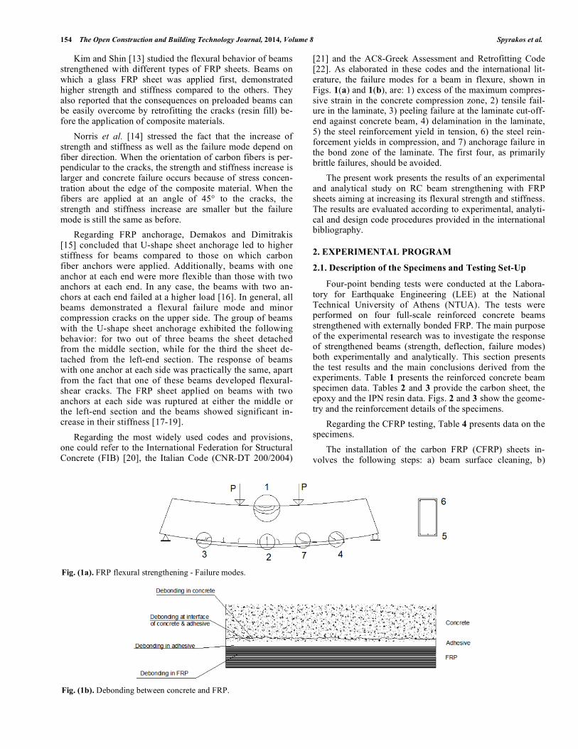
[21] and the AC8-Greek Assessment and Retrofitting Code [22]. As elaborated in these codes and the international lit-erature, the failure modes for a beam in flexure, shown in Figs. 1(a) and 1(b), are: 1) excess of the maximum compres-sive strain in the concrete compression zone, 2) tensile fail-ure in the laminate, 3) peeling failure at the laminate cut-off-end against concrete beam, 4) delamination in the laminate, 5) the steel reinforcement yield in tension, 6) the steel rein-forcement yields in compression, and 7) anchorage failure in the bond zone of the laminate. The first four, as primarily brittle failures, should be avoided.
The present work presents the results of an experimental and analytical study on RC beam strengthening with FRP sheets aiming at increasing its flexural strength and stiffness. The results are evaluated according to experimental, analyti-cal and design code procedures provided in the international bibliography.
2. EXPERIMENTAL PROGRAM
2.1. Description of the Specimens and Testing Set-Up
Four-point bending tests were conducted at the Labora-tory for Earthquake Engineering (LEE) at the National Technical University of Athens (NTUA). The tests were performed on four full-scale reinforced concrete beams strengthened with externally bonded FRP. The main purpose of the experimental research was to investigate the response of strengthened beams (strength, deflection, failure modes) both experimentally and analytically. This section presents the test results and the main conclusions derived from the experiments. Table 1 presents the reinforced concrete beam specimen data. Tables 2 and 3 provide the carbon sheet, the epoxy and the IPN resin data. Figs. 2 and 3 show the geome-try and the reinforcement details of the specimens.
Regarding the CFRP testing, Table 4 presents data on the specimens.
The installation of the carbon FRP (CFRP) sheets in-volves the following steps: a) beam surface cleaning, b)
Fig. (1a). FRP flexural strengthening - Failure modes.
Fig. (1b). Debonding between concrete and FRP.

Experimental and Analytical Study The Open Construction and Building Technology Journal, 2014, Volume 8 155
smoothing of beam edges to create appropriate curvature, c) launching of water under pressure and then drying the con-crete surface until the beam moisture is <4%, d) coating of concrete application area with resin, and e) application of FRP sheets. When the ARDFIX system was applied, the anchors were placed prior to step (e) by proper drilling and use of 5cm carbon strips as shown in Figs. 4(a) and 4(b).
Table 1. Concrete section no 1 data.
Beam Section (Height h –
Width b) 50cm x 25cm
Concrete average compres-
sive strength fcm= 20 MPa
Steel type S500
Steel Modulus of Elasticity Es= 200 GPa
Compression reinforcement 2 14 Ascom=3.079 cm2
Tension reinforcement 2 14 Asten=3.079 cm2
Transverse reinforcement
diameter w= 8 mm
Compression reinforcement
diameter Lt= 14 mm
Tension reinforcement
diameter Lb= 14 mm
Concrete cover c= 2.00 cm
Beam length l = 4.5 m
Distance of tension rein-
forcement from edge db=c+ w+0.5 Lb= 3.50 cm
Distance of compression
reinforcement from edge dt=c+ w+0.5 Lt= 3.50 cm
Table 2. Carbon sheet data.
Modulus of Elasticity Ej= 240 GPa
Characteristic value of tensile strength ffuk= 3500 MPa
Characteristic value of ultimate strain fuk= 1.5%
Thickness of fabric tj= 0.17 mm
Width of fabric wj = 0.20 m
Number of layers of fabric nj = 3
Table 3. Epoxy and IPN resin data.
ERC= 2.50 GPa Modulus of Elasticity
EIPN= 3.00 GPa
RC= 2.8 – 3.0‰ Elongation at Break
IPN= 1.2 – 2.5‰
Fig. (2). Geometry and reinforcement details of tested beams.
Fig. (3). Strengthened RC specimens.
Table 4. Data on the specimens.
Specimen 0: Concrete beam without the FRP strengthening system.
Specimen 1:
FRP strengthening system with 3 layers of BETONTEX
GV330-U-HT,
wj=200mm carbon sheets, resin type: BETONTEX
RC01-RC02, no ARDFIX connector.
Specimen 2:
Strengthening system with 3 layers of BETONTEX
GV330-U-HT,
wj=200mm carbon sheets, resin type: BETONTEX
RC01-RC02 and U-Shape ties.
Specimen 3:
Strengthening system of with 3 layers of BETONTEX
GV330-U-HT,
wj=200mm carbon sheets, resin type: BETONTEX
RC01-RC02 with ARDFIX connectors.
Specimen 4:
Strengthening system with 3 layers of BETONTEX
GV330- U-HT,
wj=200mm carbon sheets, resin type: BETONTEX
IPN01-IPN02, no ARDFIX connectors.
Fig. (4a). Drilling and placing of anchors.

156 The Open Construction and Building Technology Journal, 2014, Volume 8 Spyrakos et al.
Fig. (4b). Placing of anchors and CFRP application.
2.2. Test Results
All specimens were tested in four-point bending up to failure. The experimental set-up is shown in Fig. 5. The load-deflection curves obtained for each specimen are pre-sented in Fig. 6. The positions of the deflection meters are indicated as D1, D2 and D3 in Fig. 5(c).
2.3. Observed Modes of Failure
For specimen 1, debonding failure between FRP and concrete along the length of beam was observed. Also, flex-
ural cracks developed at mid-span of the beam as shown in Figs. (7 and 8).
For specimen 2 flexural cracks at mid-span of the beam were observed. The test stopped when failure and breaking of U-Shape ties of carbon fibers and debonding from con-crete were observed as shown in Figs. (9 and 10).
For specimen 3, flexural cracks at mid-span of the beam were observed (Fig. 11). The test ended when rupture of the carbon reinforcement at mid-span of the beam occurred (Fig. 12). During this test, no debonding between FRP and con-crete was practically observed.
For specimen 4, small horizontal cracks were initially ob-served at both ends of the beam. With load increase, flexural cracks developed and propagated upwards in the region of high bending moment, that is, between the points of applica-tion of the concentrated loads to the beam. The test stopped when debonding of the CFRP sheets from concrete was ob-served, as shown in Figs. (13 and 14). No delamination among the composite layers appeared, attributed to their good impregnation with the IPN resin.
3. ANALYSIS AND COMPARISON WITH CURRENT DESIGN PROVISIONS
As a next step, using equilibrium and compatibility re-quirements, the strains, stresses and forces developed to the
Fig. (5). Experimental setup (a) general view, (b) detail and (c) drawing.

Experimental and Analytical Study The Open Construction and Building Technology Journal, 2014, Volume 8 157
Fig. (6). Load-deflection curves for specimens 1, 2, 3 and 4, respectively.
Fig. (7). Specimen 1 - (a) CFRP debonding along the beam length, and (b) Flexural cracks at mid-span.

158 The Open Construction and Building Technology Journal, 2014, Volume 8 Spyrakos et al.
Fig. (8). Specimen 1 - Crack pattern at the end of test.
Fig. (9). Specimen 2 - Debonding of the CFRP strengthening system.
Fig. (10). Specimen 2: Crack pattern at the end of test.
Fig. (11). Specimen 3 - (a) Flexural cracks at mid-span, and (b) rupture of CFRP strengthening system.
Fig. (12). Specimen 3 - Crack pattern at the end of test.
Fig. (13). Specimen 4- Debonding the CFRP sheets at the end of the
test.
Fig. (14). Specimen 4 - Crack pattern at the end of the test.

Experimental and Analytical Study The Open Construction and Building Technology Journal, 2014, Volume 8 159
composite materials are analytically calculated, as antici-pated by the load (F) causing failure to each one of the specimens. Consequently, an analysis was contacted and a comparison between the experimentally based values and the ones obtained according to the EC8-GARC.
3.1. Analysis Procedure
The analytical calculations refer to the force-equilibrium of the concrete beam strengthened with the CFRP system, as shown schematically in Fig. 15. In all calculations that fol-low the factors of safety are taken as equal to 1.
The analytical procedure is presented only for the first specimen. The corresponding results for all the other speci-mens are presented in Table 5.
The load-deflection curve for specimen No 1 is shown in Fig. 6(a). From this curve, the measured force at failure is F = 181.45 kN and from equilibrium, including the dead load of the beam, the corresponding flexural strength is obtained via equilibrium to be: R = 143.90 kNm.
Applying an iterative analytical procedure (IAP) one can arrive at the following strains ( c, s1, s2, f) that fulfill the compatibility and equilibrium requirements at the section for
R = 143.90 kNm, that is Notice that the elongation at fail-ure caused by debonding of the composite material is
f = 6.854‰.
3.2. Calculations According to the Greek Assessment and
Retrofitting Code
According to the (EC8-GARC), failure of the strengthen-ing material occurs when
j ,crit = f jk (1)
jd =1
m
f jk (2)
where f jk is the characteristic value of material strength and
m is the factor of safety for the material.
Early debonding of the strengthening material because of inadequate bonding or inadequate anchorage at its edges occurs when
jd =1
Rd
j ,crit (3)
where Rd
is the factor of safety that accounts for all the model uncertainties and j ,crit is the material stress for debonding.
The design effective stress jd of the CFRP reinforcement is estimated according to the critical stress j,crit and has to be smaller than the jd corresponding to the worst of the follow-ing failure modes:
Fig. (15). Analysis of section subjected to bending.
c=–1.690‰
f=6.854‰
=
c (6 c)
12, c 0.002
3 c 2
3 c
, c > 0.002
= 0.606
=
8c
4 (6c), c 0.002
c (3 c 4) + 2
2 c (3 c 2), c > 0.002
= 0.366
x = d =c
c+
s
ten(h d
b) x = 9.89 cm
= x = 0.0362 m
scom
=–1.092‰ fscom
=218.40 MPa
sten
=6.256‰ fsten
=500.00 MPa
Fc= ·0.85·fcd·x·b Fc=254.51 kN
Fscom
=Ascom
·fscom
=67.24 kN (compression steel)
Fsten
=Asten
·fsten
=153.94 kN
(tension steel)
Fj1= f·Ej·nj·tj·wj=167.79 kN (tension composite)
Fc + Fscom
– Fsten
– Fj1 = 0
MR = Fc(0.5h-a)+Fj10.5h+Fsten
(0.5h-db) +Fscom
(0.5h-dt) = 143.90 kNm

160 The Open Construction and Building Technology Journal, 2014, Volume 8 Spyrakos et al.
a. Failure of the Composite Material
The ultimate strain of the composite material is equal to
frp,u=15‰.
Accordingly, the design effective stress of the CFRP re-inforcement is equal to
jd=fjk/ m=3500 MPa.
Employing the IAP, one can calculate the design moment MRd according to EC8-GARC, that is:
Yielding a flexural strength: Rd = 220.11 kNm
b. Debonding of the Composite Material
This failure mode usually occurs simultaneously with the failure of concrete cover of the longitudinal reinforcement at the edge of the FRP sheets. The EC8-GARC suggests the following approximate relationships for this failure mode:
j ,crb
debond
t jLe
b
debondfctm = 0.30 fcm
2/3= 2.210 MPa
Le =Ejt j
2 fctm= 166.41 mm
w =2 wj / b
1+ wj / b= 0.816
L=1.0 (since Lav=1750 mm > Le=166.41mm), where Lav and Le is the available and the required anchorage length, respectively. Thus,
= w· L=0.816
j,cr=588.784 MPa
j,cr= j,cr/Ej=2.453‰
Employing the IAP, the design moment MRd according to EC8-GARC is obtained: Rd = 84.75 kNm
c. Design Effective Stress jd
The CFRP reinforcement is calculated so that it can un-dertake, in cooperation with the existing reinforcement, the additional imposed moment. In order to calculate the re-quired section of strengthening CFRP reinforcement ( j) the following approximate analytical expression can be used [20]:
Aj =Mdo
z jd
do = jd z Aj
z = 0,9·(h-db) = 41.85 cm
c=–3.500‰
f=13.743‰
=
c (6 c)
12, c 0.002
3 c 2
3 c
, c > 0.002
= 0.810
=
8c
4 (6c), c 0.002
c (3 c 4) + 2
2 c (3 c 2), c > 0.002
= 0.416
x = d =c
c+
s
tend x = 10.15cm
= x = 0.0422m
scom
=–2.293‰ fscom
=458.60 MPa
sten
=12.536‰ fsten
=500.00 MPa
Fc= ·0.85·fcd·x·b Fc=349.18 kN
Fscom
=Ascom
·fscom
=141.19 kN (compression
steel)
Fsten
=Asten
·fsten
=153.94 kN (tension steel)
Fj1= f·Ej·nj·tj·wj=336.43 kN (tension composite)
Fc + Fscom
– Fsten
– Fj1 = 0
MR = Fc(0.5h-a)+Fj10.5h+Fsten
(0.5h-db) +Fscom
(0.5h-dt)=220.11 kNm
Table 5. Experimental values (F) and corresponding values (MRd, f, j) for specimens 1, 2, 3 and 4.
Specimen 1 Specimen 2 Specimen 3 Specimen 4
F=181.45 kN F=191.82 kN F=213.50 kN F=98.26 kN
MR=143.90 kNm MR=151.68 kNm MR=167.94 kNm MR=81.51 kNm
f=6.854‰ f=7.538‰ f=8.993‰ f=2.363‰
j=1644.960 MPa j=1809.120 MPa j=2158.320 MPa j=567.120 MPa

Experimental and Analytical Study The Open Construction and Building Technology Journal, 2014, Volume 8 161
a. Failure of the Composite Material
Effective Stress: jd = 3500 MPa.
Flexural Strength: = 149.40 kNm
b. Early Debonding of the Composite Material
Effective Stress: jd = 588.784 MPa.
Flexural Strength: = 25.13 kNm
A comparison between the results for the four specimens is presented in Table 5.
Comparing the results for the four specimens, it can be seen that there is a significant difference in the flexural strength of the beam for bonding the FRP fabric with epoxy RC resin, epoxy RC resin with U-Shape ties, epoxy RC resin with ARDFIX connectors and IPN resin.
Application of the connectors, in this case at a distance of 40 cm, has significantly increased the flexural strength of the beam, that is, about 76.0% of the maximum flexural strength corresponding to failure of the FRP fibers in tension.
For specimen 4, where the IPN resin was applied, a sub-stantial difference is observed when the results are compared with specimen 1. Nevertheless, consequent experience has shown that proper wetting and roughening of the contact area can increase the adhesion of IPN resin to the concrete substrate, so that the elongation at failure from debonding may well exceed 3%.
Table 6 presents the design values according to the (EC8-GARC) and Table 7 shows the test result for tha cubic specimens.
Table 6. Design values according to the (EC8-GARC).
(EC8-GARC)- (IAP) (EC8-GARC) - Mdo= jd·z·Aj
a. Failure of the a. Failure of the
Composite Material: Composite Material:
frp,u=15‰ frp,u=15‰
jd=3500 MPa jd=3500 MPa
Flexural Strength: Flexural Strength:
MRd=220.11 kNm MRd=149.40 kNm
b. Early Debonding of b. Early Debonding of
the Composite Material: the Composite Material:
frp,u=2.453‰ frp,u=2.453‰
j,cr=588.784 MPa j,cr=588.784 MPa
Flexural Strength: Flexural Strength:
MRd=84.75 kNm MRd=25.13 kNm
Comparing the results of the four specimens with the
ones calculated according to the (EC8-GARC), see Table 6, it can be stated that: when the controlling failure is debond-ing, the calculated flexural strength is much lower (less than
1/3) than the one deducted from the measurements for all of the tests with Epoxy RC resin, and close to the one calcu-lated only in specimen 4 for which the IPN was used. This clearly indicates that the EC8-GARC is very conservative, rendering a value that is about (41%) or (83%) less than the experimentally determined value when using the IAP or the approximate Mdo expression, respectively.
When calculations according to the approximate analyti-cal expression do = jd·z·Aj are performed, for either fail-ure or early debonding of the composite material, it is ob-served that the calculated flexural strength substantially dif-fers with the ones obtained according to the IAP, which means that the (EC8-GARC) expression is very conserva-tive.
In order to provide valuable measurements for the design process, pull-out tests were conducted in order to measure the debonding stress,
b
debond. Specifically, six cubic speci-
mens were constructed (three with IPN and three with epoxy RC resin) and three pull-out tests were conducted for each one of them, as shown in Fig. 16.
Fig. (16). Cubic specimens for pull-out tests.
Table 7. Tests Results for the Cubic Specimens.
Resin IPN
a) 1st Cubic Specimen
1st test: 2.97 MPa
2nd test: 2.66 MPa
3rd test: 2.37 MPa
b) 2nd Cubic Specimen
1st test: 2.21 MPa
2nd test: 2.98 MPa
3rd test: 2.60 MPa
c) 3rd Cubic Specimen
1st test: 2.38 MPa
2nd test: 2.60 Mpa
3rd test: 2.03 MPa
Mean Value of Debonding Stress:
2.53 MPa
Epoxy Resin RC
a) 4th Cubic Specimen
1st test: 1.77 MPa
2nd test: 3.56 MPa
3rd test: 1.40 MPa
b) 5th Cubic Specimen
1st test: 4.05 MPa
2nd test: 1.11 MPa
3rd test: 1.47 MPa
c) 6th Cubic Specimen
1st test: 2.81 MPa
2nd test: 2.85 MPa
3rd test: 1.77 MPa
Mean Value of Debonding Stress:
2.31 MPa
Table 8 presents the
b
debond obtained from (EC8-GARC)
and the mean debonding stresses from the pull –out tests, as well as the anchor length L
e, the critical stress correspond-

162 The Open Construction and Building Technology Journal, 2014, Volume 8 Spyrakos et al.
ing to the debonding failure stress j ,cr and the flexural strength corresponding to debonding failure for both the (EC8-GARC) provisions and the IAP.
Comparing the calculated debonding stress b
debond ac-
cording to the (EC8-GARC) with the one obtained from the pull-out tests to the cubic specimens, it can be stated that the calculations according to [22] are close to the ones obtained from the tests. Nevertheless, it should be common practice to perform pull-out tests as specified in pertinent codes, e.g., ref. [20].
Also comparison between the MR and do the from Ta-ble 6 and 8, respectively, it is observed that the flexural strength calculated according to the EC8-GARC is always much lower than the one resulting from the experiments, indicating that the code is conservative. However, for the specimen 4, the experiment and EC8-GARC yield practically identical flexural strengths.
CONCLUSION
Based on the results presented herein, the following con-clusions can be drawn:
• The CFRP application led to an increase of the beam
strength and stiffness. Although all specimens were rein-forced with identical layers of CFRP, it was observed
that different resin and anchorage systems significantly
influenced the resulting strength and stiffness of the specimens. The best results were achieved with connec-
tors.
• The results of the experiments have verified that: the
code [20] evaluated increase in bending strength is sub-
stantially underestimated, when delamination is the mode of failure.
• All tests verified a common design practice, that is, a
minimum strain of 3% at failure can be considered in de-sign even with the presence of a minimum number of an-
chors. This is an observation of particular importance in
avoiding overdesign of CFRP strengthened structural members in bending. Nevertheless, such a practice
should always be accompanied by in-situ pull-out testing.
• Regarding the EC8-GARC code, the experimental and
analytical work demonstrated that: a) the debonding stress
b
debond calculated according to the EC8-GARC is
quite accurate, b) when debonding is the mode of failure,
the strength calculated with the analytical models pro-posed by the Code [22] are conservative, and c) the ap-
proximate analytical expression do = jd·z·Aj of the
Code is, by no means an accurate analytical expression, greatly underestimating the increase achieved by the
CFRP reinforcement.
• The recommended practice would be to perform in-situ
pull-out tests, calculate the strength through satisfaction
of equilibrium and compatibility requirements, that is use of the IAP, and installation of a minimum number of an-
chors.
• Spacing of anchors in the range of 2/3rds
of the beam height led to dramatically higher debonding strains; thus,
allowing a more efficient use or the CFRP reinforcement.
However, more research is needed in order to assess the effect of anchoring systems and arrive at well docu-
mented design recommendations.
CONFLICT OF INTEREST
The authors confirm that this article content has no con-flict of interest.
ACKNOWLEDGEMENTS
The FRP were provided by BETONTEX®
and the appli-cation of the strengthening material was performed under the supervision of technical personnel of the company.
REFERENCES
[1] J. G. Teng, H. Yuan, and J. F. Chen, “FRP-to-concrete interfaces
between two adjacent cracks: Theoretical model for debonding failure”, International Journal of Solids & Structures, vol. 43, pp.
5750-78, 2006. [2] K. V. Subramaniam, C. Carloni, and L. Nobile, “Width effect in the
interface fracture during shear debonding of FRP sheets from con-crete”, Engineering Fracture Mechanics, vol. 74, pp. 578-94, 2007.
[3] F. Chen, and P. Qiao, “Debonding analysis of FRP-concrete be-tween two balanced adjacent flexural cracks in plated beams”, In-
Table 8. Comparative Table of Results for the cubic specimens pull-out tests.
Greek Assessment and Retrofitting Code Cubic pull-out tests Resin IPN Cubic pull-out tests Epoxy Resin RC
b
debond 2.21 MPa 2.53 MPa 2.31 MPa
166.41 mm 155.53 mm 162.77 mm
588.784 MPa 629.970 MPa 601.958 MPa
j,cr 2.453‰ 2.625‰ 2.508‰
do= j·z·Aj 25.13 kNm 26.89 MPa 25.70 MPa
IAP 84.75 kNm 90.82 kNm 86.65 kNm

Experimental and Analytical Study The Open Construction and Building Technology Journal, 2014, Volume 8 163
ternational Journal of Solids & Structures, vol. 46, pp. 2618-28,
2009. [4] J. F. Chen, H. Yuan, and J. G. Teng, “Debonding failure along a
softening FRP-to-concrete interface between two adjacent cracks in concrete members”, Engineering Structures, vol. 29, pp. 259-270,
2007. [5] O. Gunes, O. Buyukozturk, and E. Karaka, “A fracture-based
model for FRP debonding in strengthened beams”, Engineering Fracture Mechanics, vol. 76, pp. 1897-909, 2009.
[6] L. Ombres, “Prediction of intermediate crack debonding failure in FRP-strengthened reinforced concrete beams”, Composite Struc-
tures, vol. 92, pp. 322-329, 2010. [7] K. Benzarti, F. Freddi, and M. Frémond, “A damage model for
predicting the durability of bonded assemblies. Part I: Debonding behavior of FRP strengthened concrete members”, Construction &
Building Materials, vol. 25, pp. 547-55, 2011. [8] F. Ceroni, M. Pecce, S. Matthys, and L. Taerwe, “Debonding
strength and anchorage devices for reinforced concrete elements strengthened with FRP sheets”, Composites Part: B, vol. 39, pp.
429-41, 2008. [9] D. Bruno, R. Carpino, and F. Greco, “Modeling of mixed mode
debonding in externally FRP reinforced beams”, Composite Sci-ence & Technology, vol. 67, pp. 1459-1474, 2007.
[10] J. R. Casas, and J. Pascual, “Debonding of FRP in bending: Simpli-fied model and experimental validation”, Construction & Building
Materials, vol. 21, pp. 1940-1949, 2007. [11] P. Alagusundaramoorthy, I. E. Harik, and C. C. Choo, “Flexural
behavior of R/C beams strengthened with Carbon Fiber Reinforced Polymer Sheets or Fabric”, Journal of Composites for Construc-
tion, vol. 7, No. 4, pp. 292-301, 2003. [12] K. Takeda, Y. Mitsui, K. Murakami, H. Sakai, and M. Nakamura,
“Flexural Behavior of reinforced concrete beams strengthened with Carbon Fiber sheets”, Composites Part A, vol. 27, No. A, pp. 981-
987, 1996.
[13] H. S. Kim, and Y. S. Shin, “Flexural behavior of Reinforced Con-
crete (RC) beams retrofitted with Hybrid Fiber Reinforced Poly-mers (FRPs) under sustaining loads”, Composite Structures, vol.
93, pp. 802-811, 2011. [14] T. Norris, “Flexural behavior of Reinforced Concrete (RC) Beams
retrofitted with hybrid fiber reinforced polymers (FRPs) under sus-taining loads”, Journal of Structural Engineering, vol. 123, No. 7,
pp. 903-911, 1997. [15] C. B. Demakos, and G. Dimitrakis, “On the Effect of FRP Sheet
Composite Anchorage to Flexural Behavior of Reinforced Concrete Beams”, in Proceedings of Excellence in Concrete Construction
through Innovation, 2009, pp. 345-355. [16] C. B. Demakos, C. C. Repapis, and D. Drivas, “Investigation of
structural response of reinforced concrete beams strengthened with anchored FRPs”, The Open Construction and Building Technology
Journal, vol. 7, pp. 146-57, 2013. [17] C. C. Spyrakos, “Structural Strengthening for Seismic Loads,” (in
Greek), Athens: Technical Chamber of Greece (T. . .), 2004. [18] D. Gay, S. V. Hoa, and S. W. Tsai, “Composite Materials Design
and Applications,” Boca Raton: CRC PRESS, 2002. [19] ACI 440.3R - 04, “Guide Test Methods for Fiber-Reinforced
Polymers (FRPs) for reinforcing or strengthening concrete struc-tures”, Reported by ACI Committee 440, 2004
[20] International Federation for Structural Concrete (FIB). “Externally Bonded FRP Reinforcement for RC Structures – Bulletin 14”, July,
2001. [21] Consiglio Nazionale Delle Ricerche. Instruzioni per la Progettazio-
ne, l’ Esecuzione ed il Controllo di Interventi di Consolidamento Statico mediante l’ utillizzo di Compositi Fibrorinforzati, CNR-DT
200/2004. [22] Earthquake Planning and Protection Organization. Eurocode 8 –
Greek Assessment and Retrofitting Code (EC8-GARC), Jan. 2012.
Received: December 23, 2013 Revised: June 04, 2014 Accepted: June 04, 2014
© Spyrakos et al.; Licensee Bentham Open.
This is an open access article licensed under the terms of the Creative Commons Attribution Non-Commercial License (http://creativecommons.org/-
licenses/by-nc/3.0/) which permits unrestricted, non-commercial use, distribution and reproduction in any medium, provided the work is properly cited.