
NATIONAL TECHNICAL UNIVERSITY OF ATHENS...
46
NATIONAL TECHNICAL UNIVERSITY OF ATHENS LABORATORY FOR EARTHQUAKE ENGINEERING Seismic design of bridges Lecture 1 Ioannis N. Psycharis
Transcript of NATIONAL TECHNICAL UNIVERSITY OF ATHENS...
NATIONAL TECHNICAL UNIVERSITY OF ATHENS LABORATORY FOR EARTHQUAKE ENGINEERING
Seismic design of bridges
Lecture 1
Ioannis N. Psycharis
I. N. Psycharis “Seismic design of bridges” 2
Bridge types
I. N. Psycharis “Seismic design of bridges” 3
Common bridge types
Horizontal slabs or girders supported by abutments and piers.
Common types:
● Slab type
● I-beam type
● Box girder
I. N. Psycharis “Seismic design of bridges” 4
Common bridge types
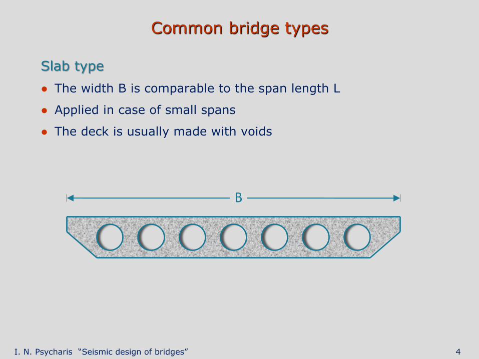
Slab type
● The width B is comparable to the span length L
● Applied in case of small spans
● The deck is usually made with voids
B
I. N. Psycharis “Seismic design of bridges” 5
Common bridge types
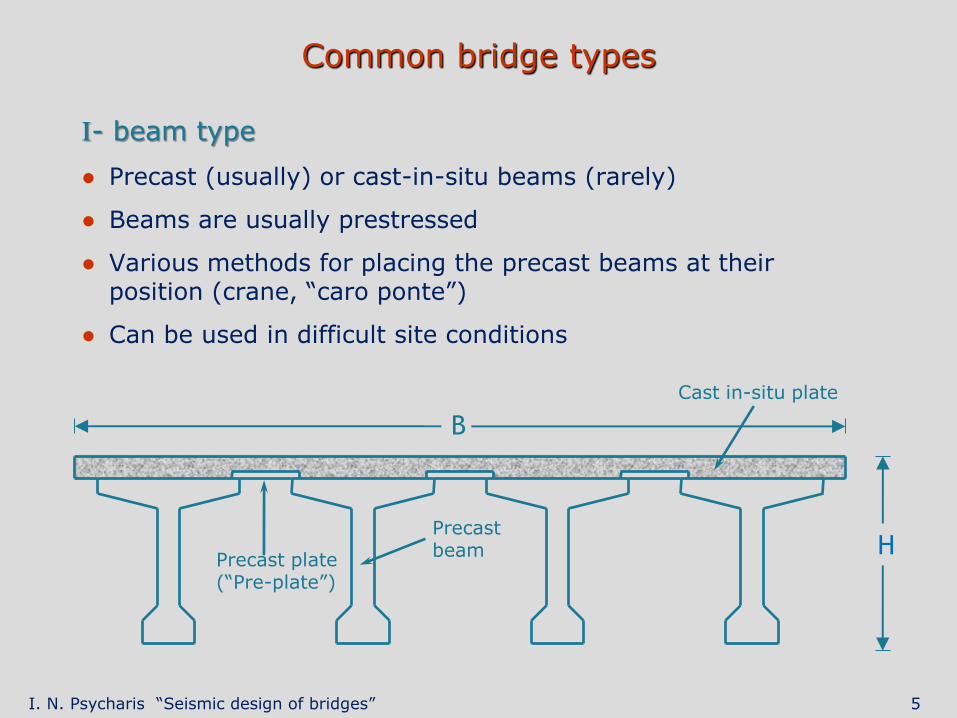
I- beam type
● Precast (usually) or cast-in-situ beams (rarely)
● Beams are usually prestressed
● Various methods for placing the precast beams at their position (crane, “caro ponte”)
● Can be used in difficult site conditions
B
H Precast plate (“Pre-plate”)
Cast in-situ plate
Precast beam
I. N. Psycharis “Seismic design of bridges” 6
Common bridge types
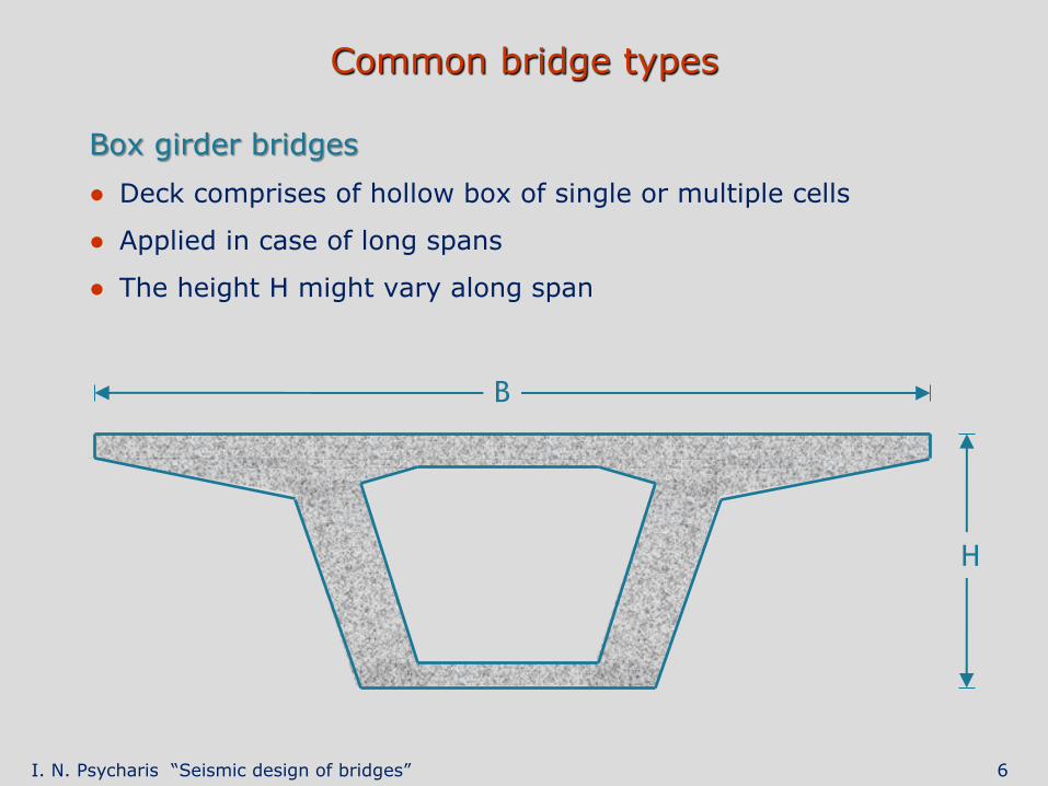
Box girder bridges
● Deck comprises of hollow box of single or multiple cells
● Applied in case of long spans
● The height H might vary along span
B
H
I. N. Psycharis “Seismic design of bridges” 7
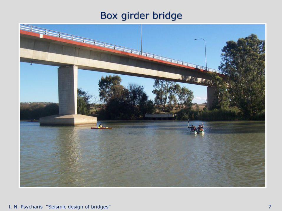
Box girder bridge
I. N. Psycharis “Seismic design of bridges” 8
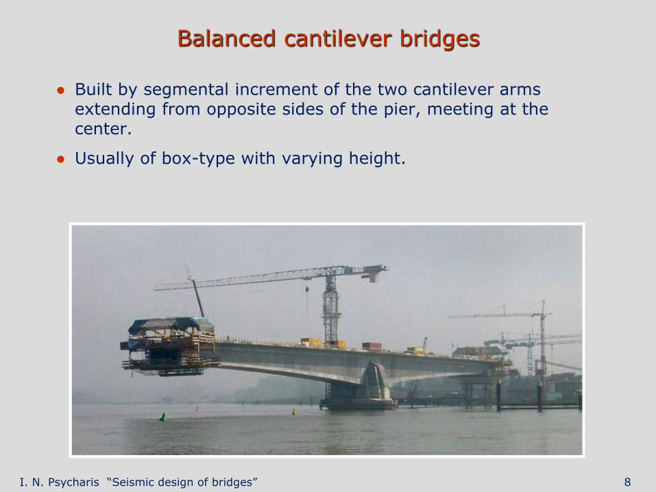
Balanced cantilever bridges
● Built by segmental increment of the two cantilever arms extending from opposite sides of the pier, meeting at the center.
● Usually of box-type with varying height.
I. N. Psycharis “Seismic design of bridges” 9
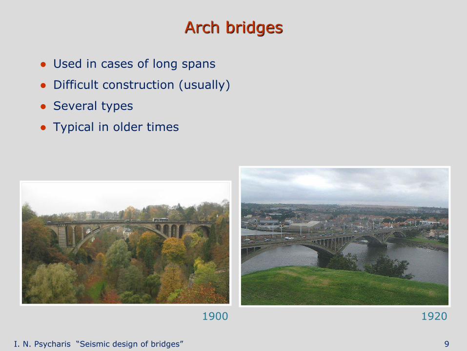
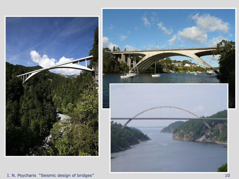
Arch bridges
● Used in cases of long spans
● Difficult construction (usually)
● Several types
● Typical in older times
1900 1920
I. N. Psycharis “Seismic design of bridges” 10
I. N. Psycharis “Seismic design of bridges” 11
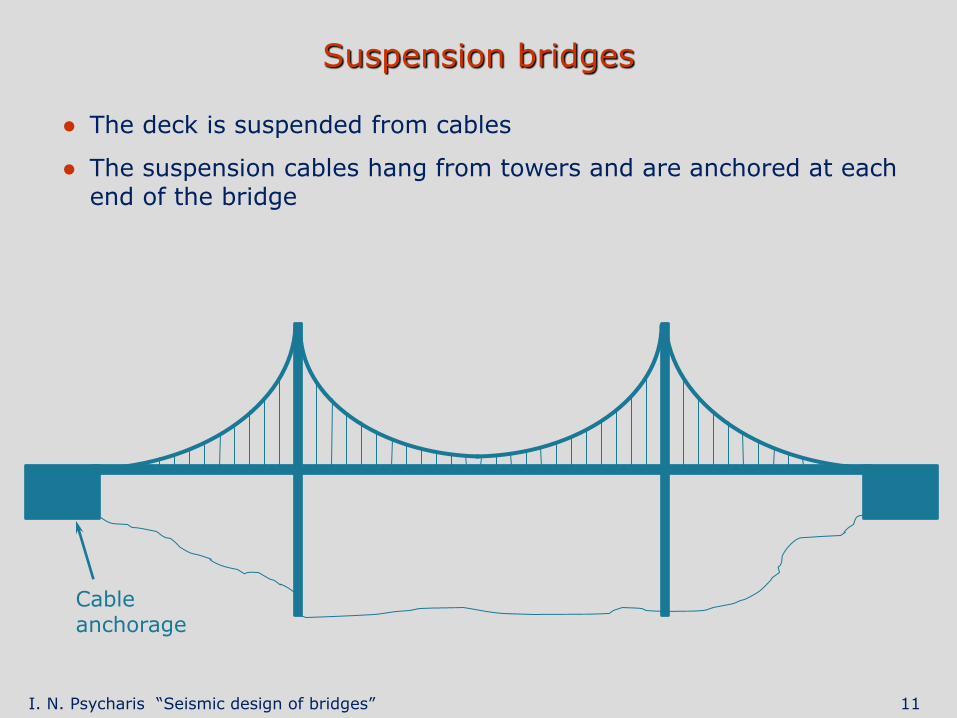
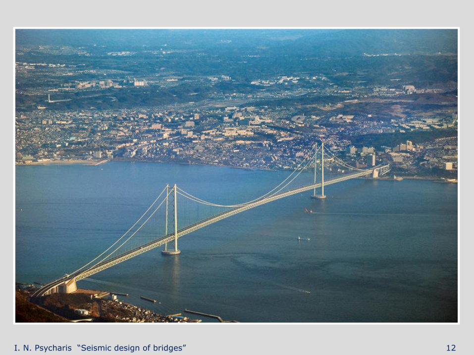
Suspension bridges
● The deck is suspended from cables
● The suspension cables hang from towers and are anchored at each end of the bridge
Cable anchorage
I. N. Psycharis “Seismic design of bridges” 12
I. N. Psycharis “Seismic design of bridges” 13
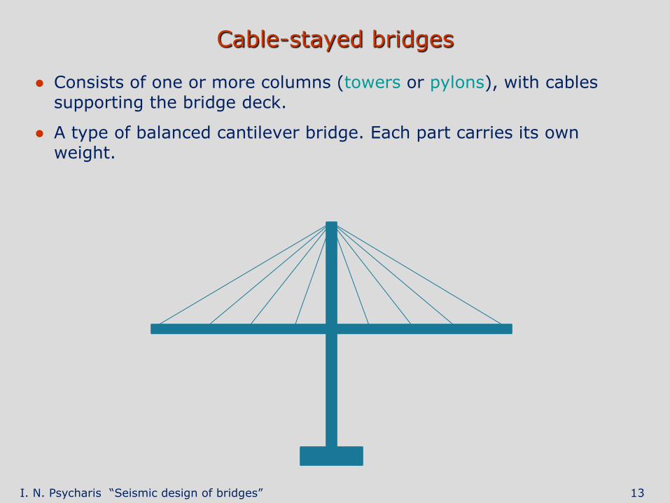
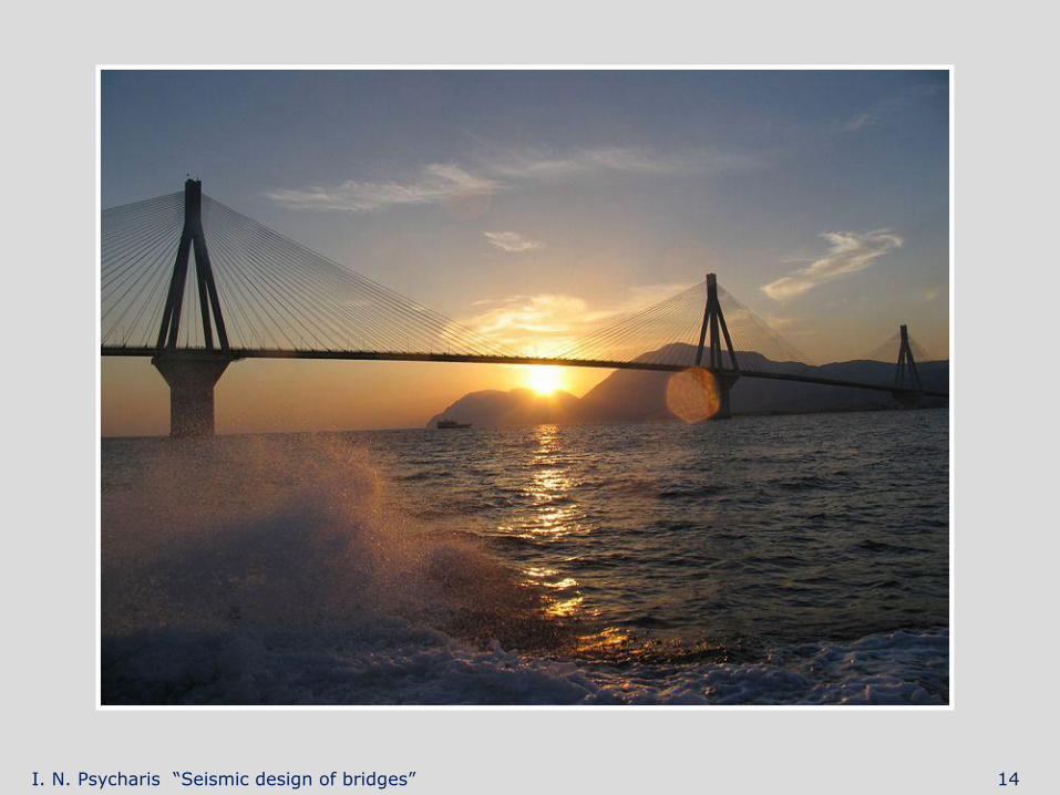
Cable-stayed bridges
● Consists of one or more columns (towers or pylons), with cables supporting the bridge deck.
● A type of balanced cantilever bridge. Each part carries its own weight.
I. N. Psycharis “Seismic design of bridges” 14
I. N. Psycharis “Seismic design of bridges” 15
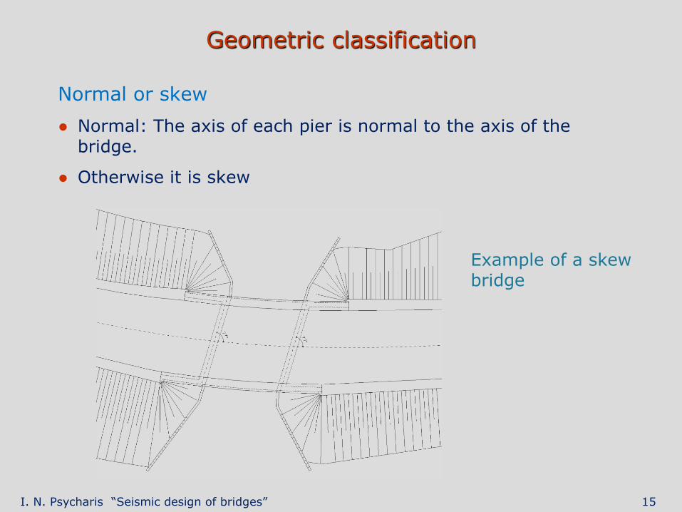
Geometric classification
Normal or skew
● Normal: The axis of each pier is normal to the axis of the bridge.
● Otherwise it is skew
Example of a skew bridge
I. N. Psycharis “Seismic design of bridges” 16
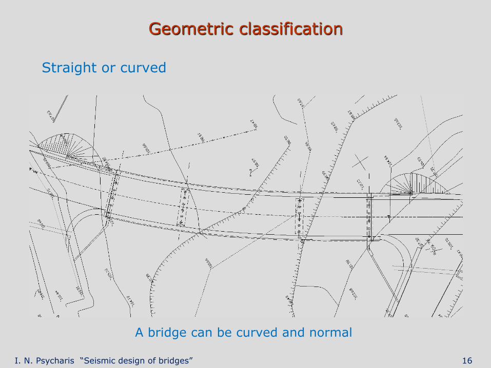
Geometric classification
Straight or curved
A bridge can be curved and normal
I. N. Psycharis “Seismic design of bridges” 17
Structural considerations
I. N. Psycharis “Seismic design of bridges” 18
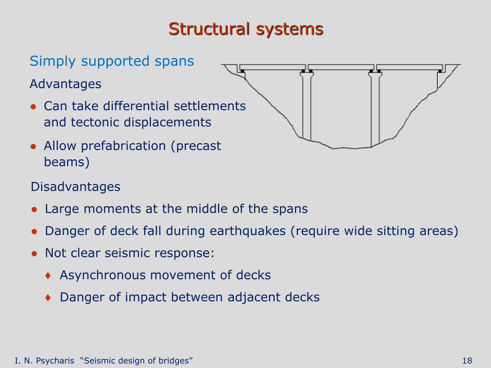
Structural systems
Simply supported spans
Advantages
● Can take differential settlements
and tectonic displacements
● Allow prefabrication (precast
beams)
Disadvantages
● Large moments at the middle of the spans
● Danger of deck fall during earthquakes (require wide sitting areas)
● Not clear seismic response:
♦ Asynchronous movement of decks
♦ Danger of impact between adjacent decks

I. N. Psycharis “Seismic design of bridges” 19
Structural systems
Continuous deck
Advantages
● Good distribution of moments between supports and spans → small
deck thickness
● Good seismic behavior:
♦ The deck acts as a diaphragm →
all piers move similarly
♦ Practically, no danger of deck fall
Disadvantages
● Sensitive to differential settlements of piers
● Cannot accommodate tectonic movements
I. N. Psycharis “Seismic design of bridges” 20
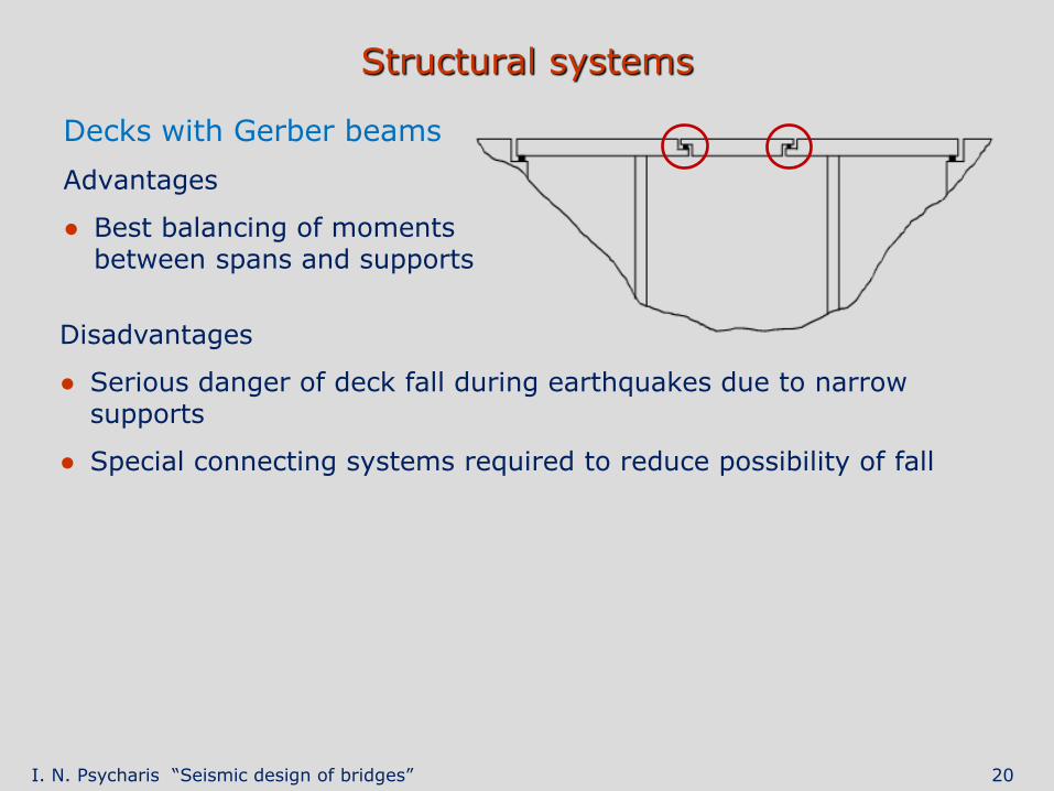
Structural systems
Decks with Gerber beams
Advantages
● Best balancing of moments between spans and supports
Disadvantages
● Serious danger of deck fall during earthquakes due to narrow supports
● Special connecting systems required to reduce possibility of fall
I. N. Psycharis “Seismic design of bridges” 21
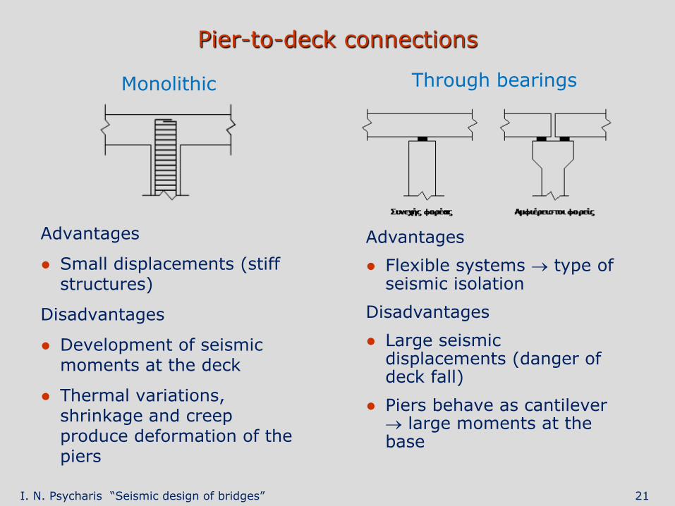
Pier-to-deck connections
Monolithic
Advantages
● Small displacements (stiff structures)
Disadvantages
● Development of seismic moments at the deck
● Thermal variations, shrinkage and creep produce deformation of the piers
Through bearings
Advantages
● Flexible systems type of seismic isolation
Disadvantages
● Large seismic displacements (danger of deck fall)
● Piers behave as cantilever large moments at the base
I. N. Psycharis “Seismic design of bridges” 22
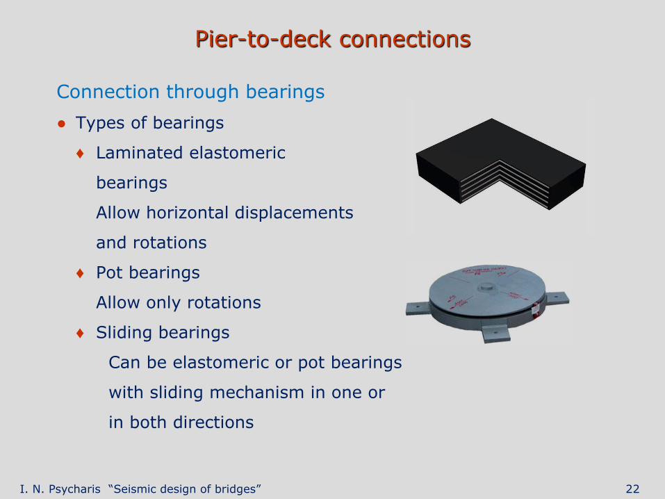
Pier-to-deck connections
Connection through bearings
● Types of bearings
♦ Laminated elastomeric
bearings
Allow horizontal displacements
and rotations
♦ Pot bearings
Allow only rotations
♦ Sliding bearings
Can be elastomeric or pot bearings
with sliding mechanism in one or
in both directions
I. N. Psycharis “Seismic design of bridges” 23
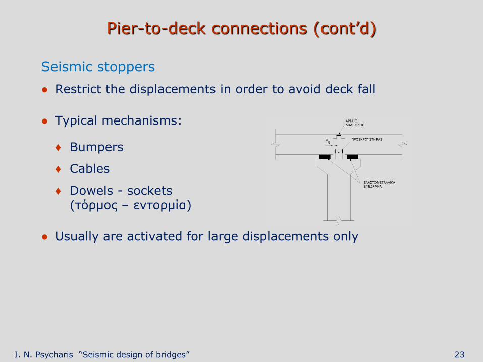
Pier-to-deck connections (cont’d)
Seismic stoppers
● Restrict the displacements in order to avoid deck fall
● Typical mechanisms:
♦ Bumpers
♦ Cables
♦ Dowels - sockets (τόρμος – εντορμία)
● Usually are activated for large displacements only
I. N. Psycharis “Seismic design of bridges” 24
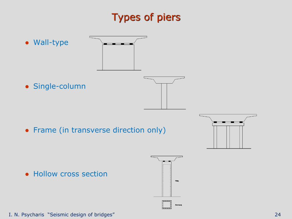
Types of piers
● Wall-type
● Single-column
● Frame (in transverse direction only)
● Hollow cross section
I. N. Psycharis “Seismic design of bridges” 25
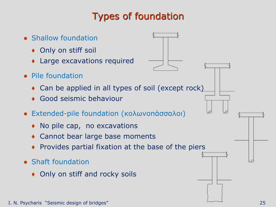
Types of foundation
● Shallow foundation
♦ Only on stiff soil
♦ Large excavations required
● Pile foundation
♦ Can be applied in all types of soil (except rock)
♦ Good seismic behaviour
● Extended-pile foundation (κολωνοπάσσαλοι)
♦ No pile cap, no excavations
♦ Cannot bear large base moments
♦ Provides partial fixation at the base of the piers
● Shaft foundation
♦ Only on stiff and rocky soils
I. N. Psycharis “Seismic design of bridges” 26
Damage from earthquakes
I. N. Psycharis “Seismic design of bridges” 27
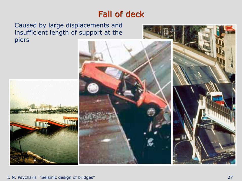
Fall of deck
Caused by large displacements and insufficient length of support at the piers
I. N. Psycharis “Seismic design of bridges” 28
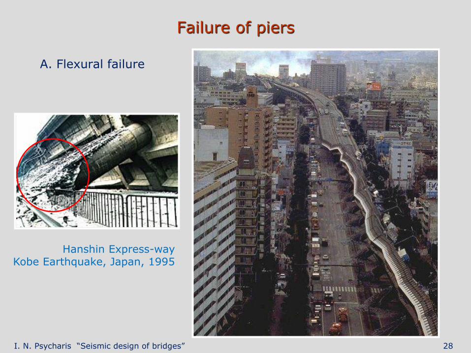
Failure of piers
A. Flexural failure
Hanshin Express-way Kobe Earthquake, Japan, 1995
I. N. Psycharis “Seismic design of bridges” 29
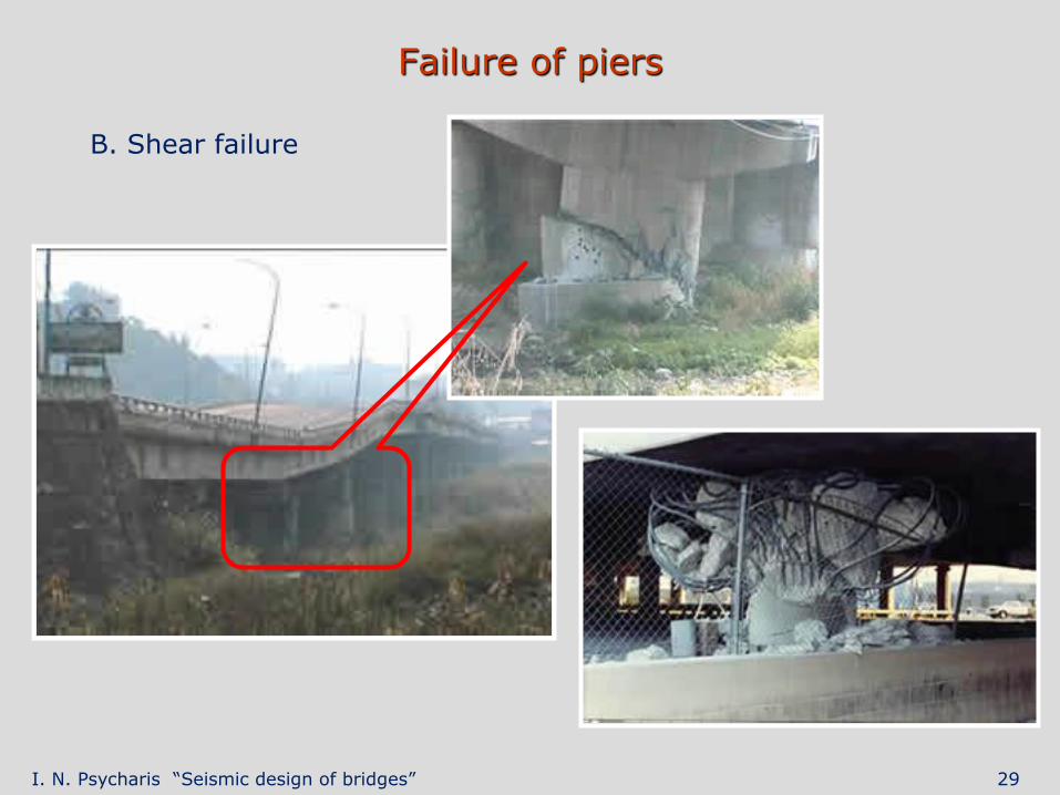
Failure of piers
B. Shear failure
I. N. Psycharis “Seismic design of bridges” 30
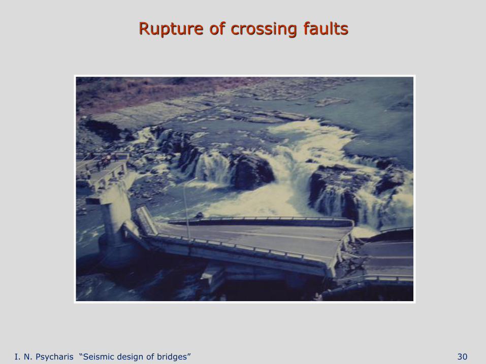
Rupture of crossing faults
I. N. Psycharis “Seismic design of bridges” 31
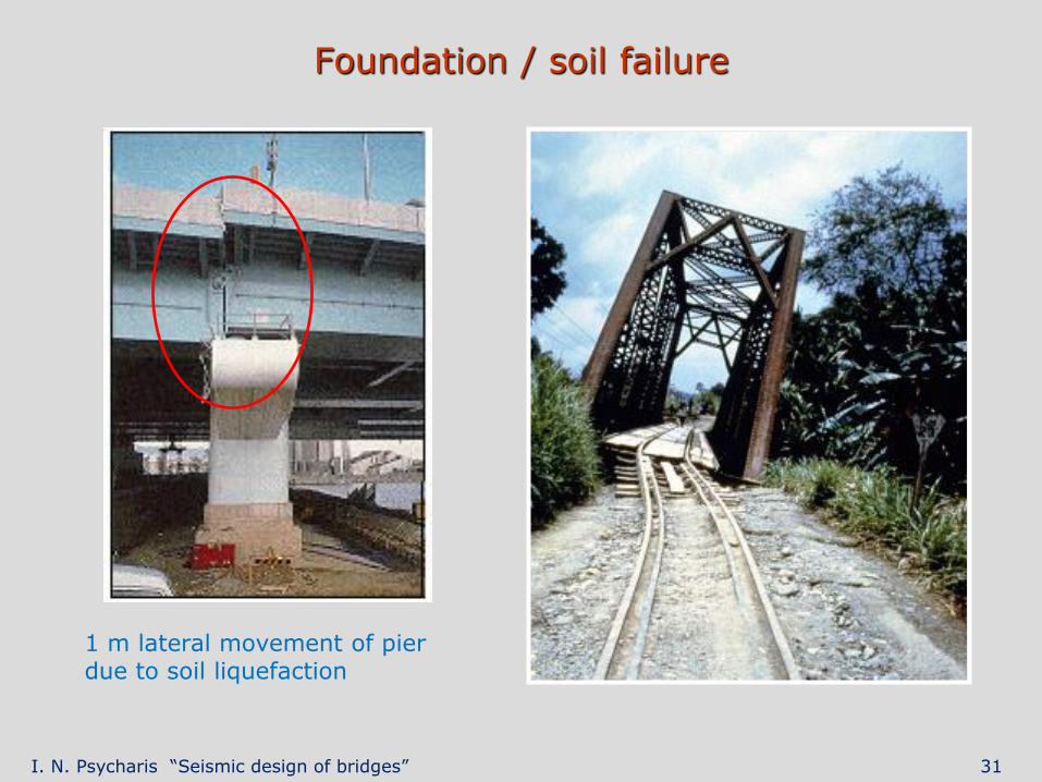
Foundation / soil failure
1 m lateral movement of pier due to soil liquefaction
I. N. Psycharis “Seismic design of bridges” 32
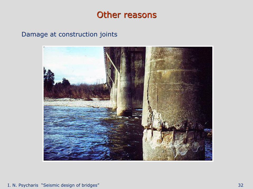
Other reasons
Damage at construction joints
I. N. Psycharis “Seismic design of bridges” 33
Seismic design
I. N. Psycharis “Seismic design of bridges” 34
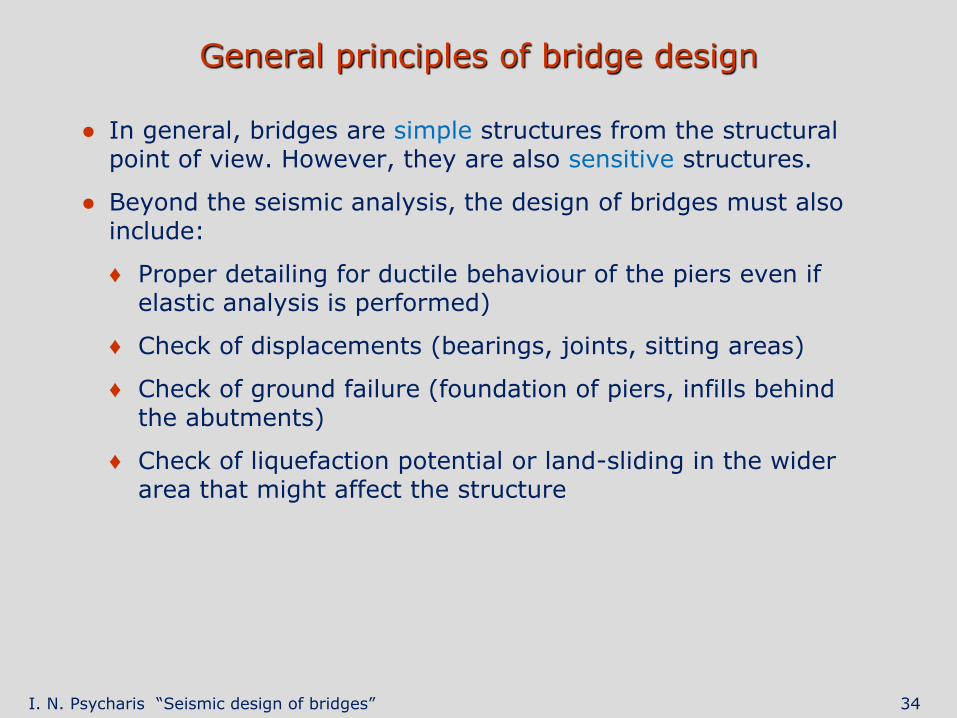
General principles of bridge design
● In general, bridges are simple structures from the structural point of view. However, they are also sensitive structures.
● Beyond the seismic analysis, the design of bridges must also include:
♦ Proper detailing for ductile behaviour of the piers even if elastic analysis is performed)
♦ Check of displacements (bearings, joints, sitting areas)
♦ Check of ground failure (foundation of piers, infills behind the abutments)
♦ Check of liquefaction potential or land-sliding in the wider area that might affect the structure
I. N. Psycharis “Seismic design of bridges” 35
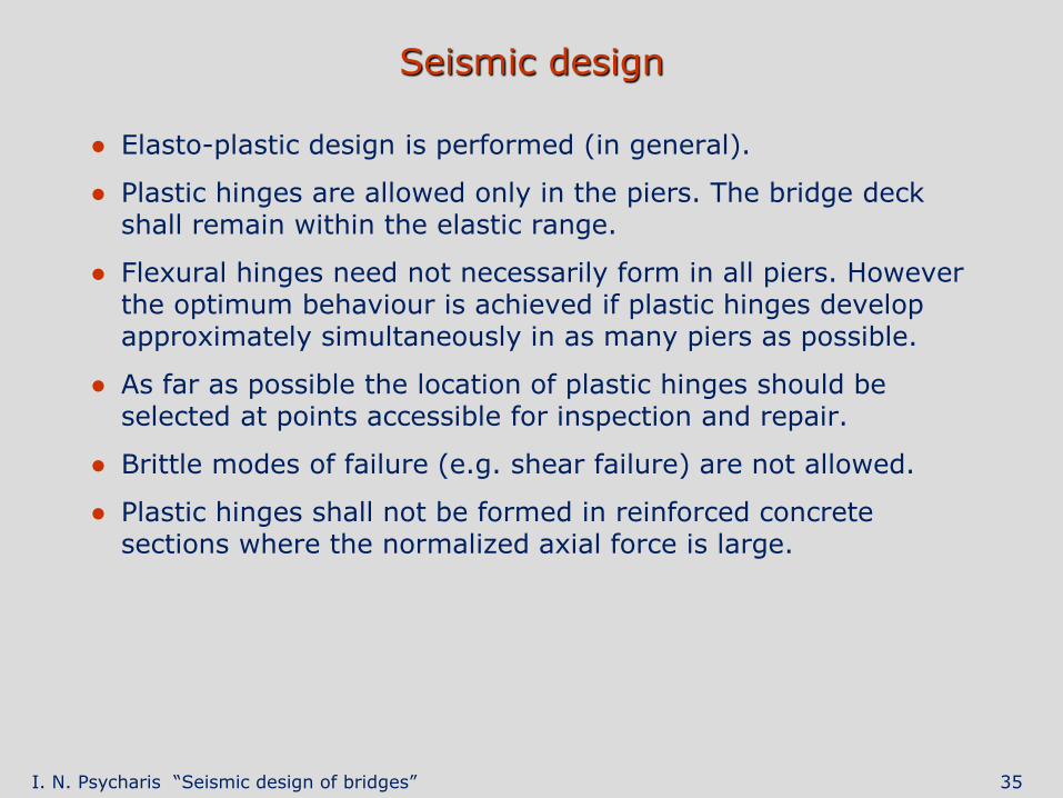
Seismic design
● Elasto-plastic design is performed (in general).
● Plastic hinges are allowed only in the piers. The bridge deck shall remain within the elastic range.
● Flexural hinges need not necessarily form in all piers. However the optimum behaviour is achieved if plastic hinges develop approximately simultaneously in as many piers as possible.
● As far as possible the location of plastic hinges should be selected at points accessible for inspection and repair.
● Brittle modes of failure (e.g. shear failure) are not allowed.
● Plastic hinges shall not be formed in reinforced concrete sections where the normalized axial force is large.
I. N. Psycharis “Seismic design of bridges” 36
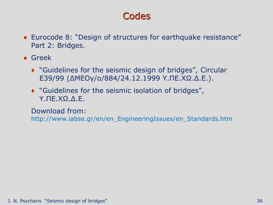
Codes
● Eurocode 8: “Design of structures for earthquake resistance” Part 2: Bridges.
● Greek
♦ “Guidelines for the seismic design of bridges”, Circular Ε39/99 (ΔΜΕΟγ/ο/884/24.12.1999 Υ.ΠΕ.ΧΩ.Δ.Ε.).
♦ “Guidelines for the seismic isolation of bridges”, Υ.ΠΕ.ΧΩ.Δ.Ε.
Download from: http://www.iabse.gr/en/en_EngineeringIssues/en_Standards.htm
I. N. Psycharis “Seismic design of bridges” 37
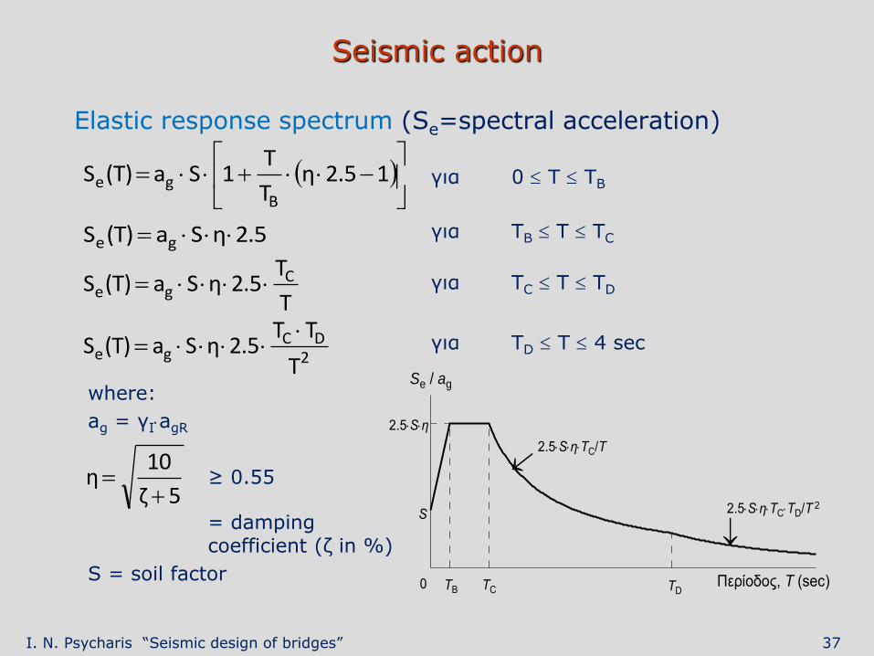
Seismic action
Elastic response spectrum (Se=spectral acceleration)
για 0 Τ ΤΒ
για ΤΒ Τ ΤC
για ΤC Τ ΤD
για ΤD Τ 4 sec
15.2η
T
T1Sa)T(S
Bge
5.2ηSa)T(S ge
T
T5.2ηSa)T(S C
ge
2DC
geT
TT5.2ηSa)T(S
5ζ
10η
Περίοδος, T (sec)
Se / ag
2.5Sη
S
0 ΤΒ ΤC TD
2.5SηTC/T
2.5SηTCTD/T 2
where:
ag = γIagR
≥ 0.55
= damping coefficient (ζ in %)
S = soil factor
I. N. Psycharis “Seismic design of bridges” 38
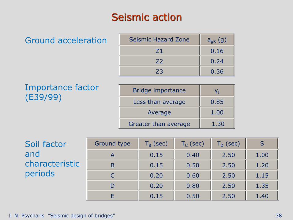
Seismic action
Ground acceleration
Importance factor (E39/99)
Soil factor and characteristic periods
Seismic Hazard Zone agR (g)
Ζ1 0.16
Ζ2 0.24
Ζ3 0.36
Bridge importance γΙ
Less than average 0.85
Average 1.00
Greater than average 1.30
Ground type ΤΒ (sec) ΤC (sec) ΤD (sec) S
Α 0.15 0.40 2.50 1.00
Β 0.15 0.50 2.50 1.20
C 0.20 0.60 2.50 1.15
D 0.20 0.80 2.50 1.35
E 0.15 0.50 2.50 1.40
I. N. Psycharis “Seismic design of bridges” 39
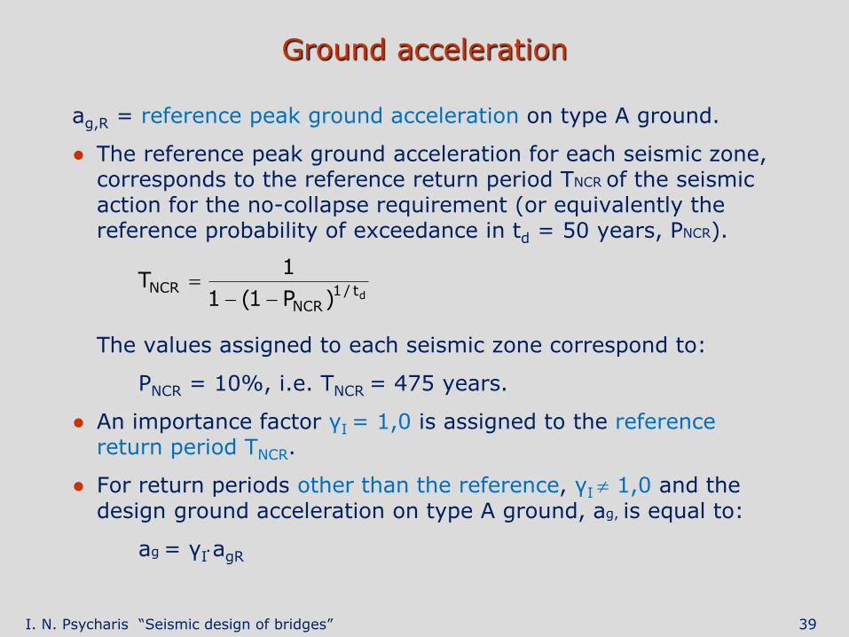
Ground acceleration
ag,R = reference peak ground acceleration on type A ground.
● The reference peak ground acceleration for each seismic zone, corresponds to the reference return period TNCR of the seismic action for the no-collapse requirement (or equivalently the reference probability of exceedance in td = 50 years, PNCR).
The values assigned to each seismic zone correspond to:
PNCR = 10%, i.e. TNCR = 475 years.
● An importance factor γI = 1,0 is assigned to the reference return period TNCR.
● For return periods other than the reference, γI 1,0 and the design ground acceleration on type A ground, ag, is equal to:
ag = γIagR
dt/1NCR
NCR)P1(1
1T
I. N. Psycharis “Seismic design of bridges” 40
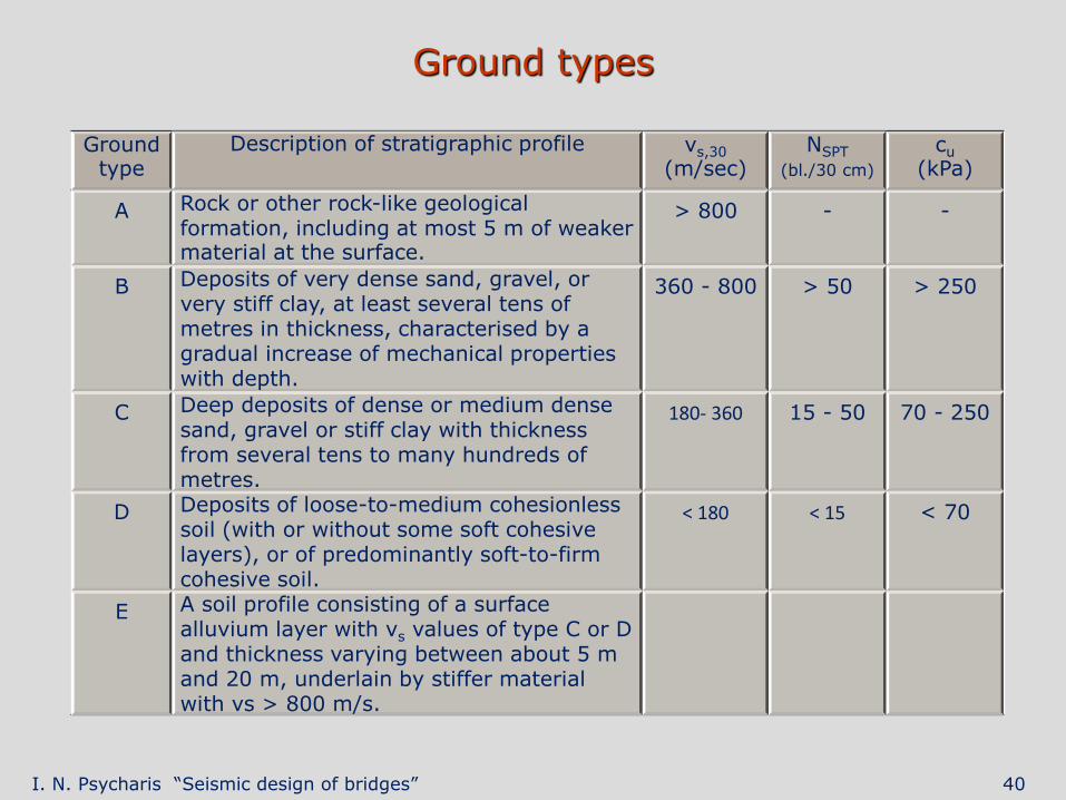
Ground types
Ground type
Description of stratigraphic profile vs,30
(m/sec) NSPT
(bl./30 cm)
cu
(kPa)
Α Rock or other rock-like geological formation, including at most 5 m of weaker material at the surface.
> 800 - -
Β Deposits of very dense sand, gravel, or very stiff clay, at least several tens of metres in thickness, characterised by a gradual increase of mechanical properties with depth.
360 - 800 > 50 > 250
C Deep deposits of dense or medium dense sand, gravel or stiff clay with thickness from several tens to many hundreds of metres.
180- 360 15 - 50 70 - 250
D Deposits of loose-to-medium cohesionless soil (with or without some soft cohesive layers), or of predominantly soft-to-firm cohesive soil.
< 180 < 15 < 70
E A soil profile consisting of a surface alluvium layer with vs values of type C or D and thickness varying between about 5 m and 20 m, underlain by stiffer material with vs > 800 m/s.
I. N. Psycharis “Seismic design of bridges” 41
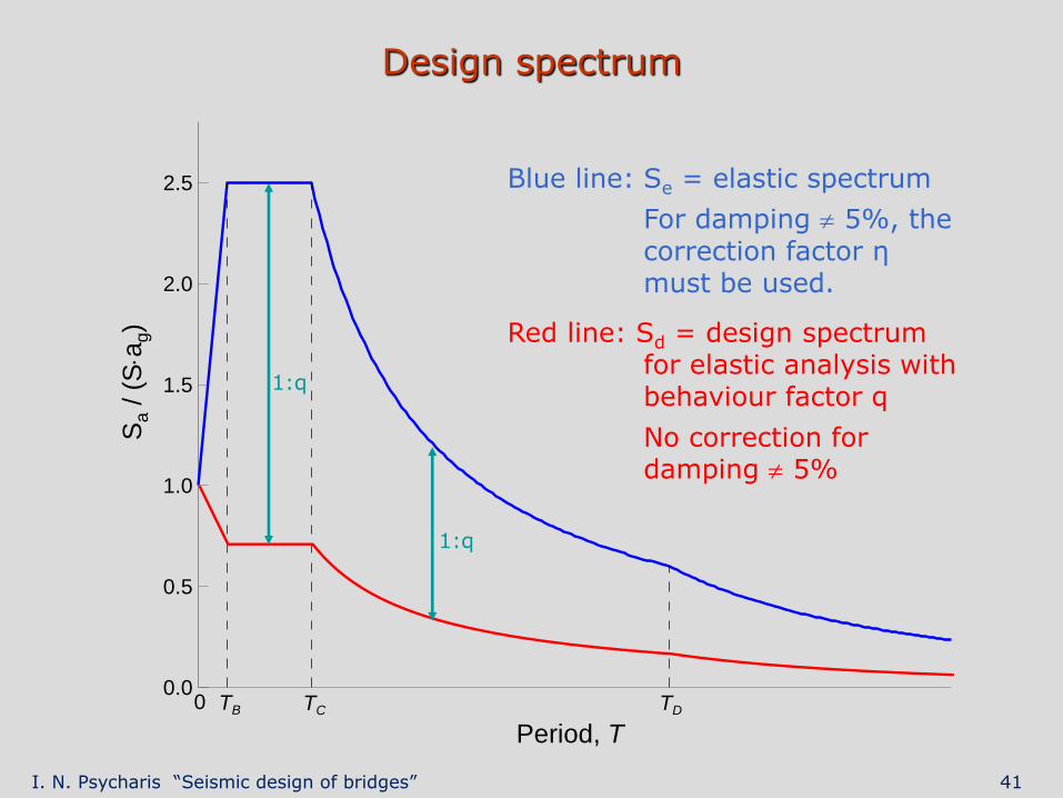
Design spectrum
Period, T
0.0
0.5
1.0
1.5
2.0
2.5
Sa /
(S
ag
R)
TB TC TD0
1:q
1:q
Sa / (
Sa
g)
Blue line: Se = elastic spectrum
For damping 5%, the correction factor η must be used.
Red line: Sd = design spectrum for elastic analysis with behaviour factor q
No correction for damping 5%
I. N. Psycharis “Seismic design of bridges” 42
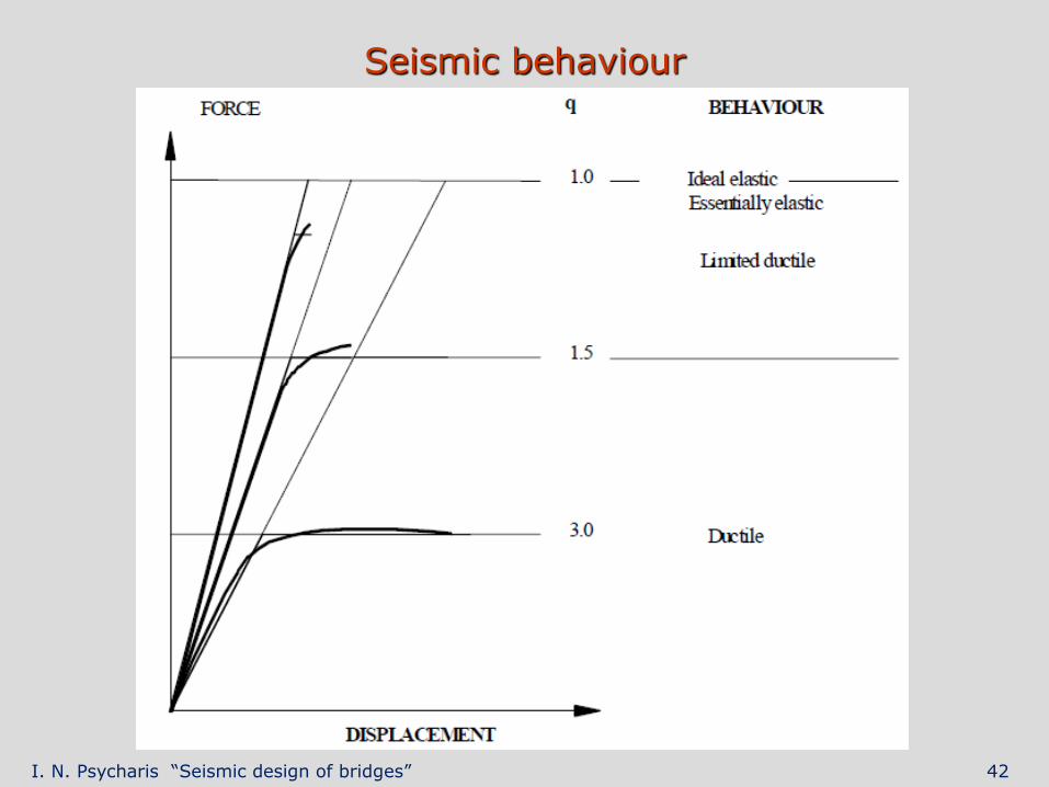
Seismic behaviour
I. N. Psycharis “Seismic design of bridges” 43
Design for ductile behaviour
● Preferred in regions of moderate to high seismicity (economic and safety reasons)
● In bridges of ductile behaviour it is expected that flexural plastic hinges will be formed, normally in the piers, which act as the primary energy dissipating components.
● As far as possible the location of plastic hinges should be selected at points accessible for inspection and repair
● The bridge deck must remain within the elastic range
● Plastic hinges are not allowed in reinforced concrete sections where the normalised axial force ηk exceeds 0,6
● Flexural hinges need not necessarily form in all piers. However it is desired that plastic hinges develop approximately simultaneously in as many piers as possible
● Piers and abutments connected to the deck through sliding or flexible elastomeric bearings must, in general, remain within the elastic range.
I. N. Psycharis “Seismic design of bridges” 44
Limited ductile/essentially elastic behaviour
● Corresponds to a behaviour factor q ≤ 1,5
● No significant yield appears under the design earthquake
● For bridges where the seismic response may be dominated by higher mode effects (e.g cable-stayed bridges) or where the detailing for ductility of plastic hinges may not be reliable (e.g. due to the presence of high axial force or of a low shear ratio), it is preferable to select an elastic behaviour (q = 1).
I. N. Psycharis “Seismic design of bridges” 45
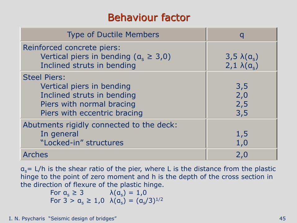
Behaviour factor
Type of Ductile Members q
Reinforced concrete piers: Vertical piers in bending (αs ≥ 3,0) Inclined struts in bending
3,5 λ(αs) 2,1 λ(αs)
Steel Piers: Vertical piers in bending Inclined struts in bending Piers with normal bracing Piers with eccentric bracing
3,5 2,0 2,5 3,5
Abutments rigidly connected to the deck: In general “Locked-in” structures
1,5 1,0
Arches 2,0
αs= L/h is the shear ratio of the pier, where L is the distance from the plastic hinge to the point of zero moment and h is the depth of the cross section in the direction of flexure of the plastic hinge. For αs ≥ 3 λ(αs) = 1,0 For 3 > αs ≥ 1,0 λ(αs) = (αs/3)1/2
I. N. Psycharis “Seismic design of bridges” 46
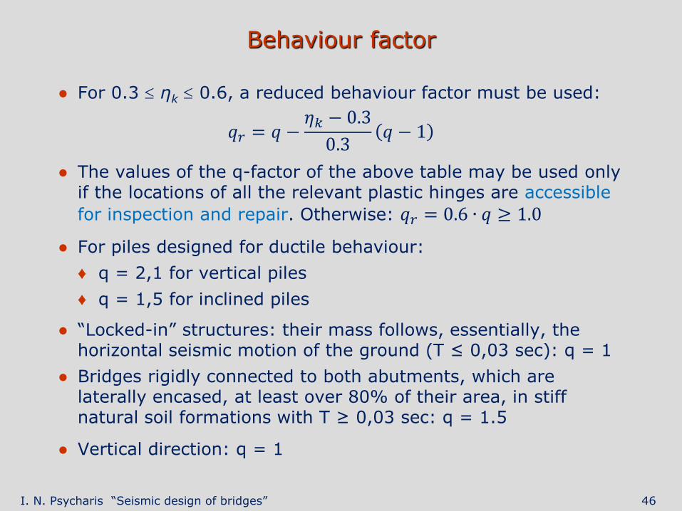
Behaviour factor
● For 0.3 ηk 0.6, a reduced behaviour factor must be used:
𝑞𝑟 = 𝑞 −𝜂𝑘 − 0.3
0.3𝑞 − 1
● The values of the q-factor of the above table may be used only if the locations of all the relevant plastic hinges are accessible
for inspection and repair. Otherwise: 𝑞𝑟 = 0.6 ∙ 𝑞 ≥ 1.0
● For piles designed for ductile behaviour:
♦ q = 2,1 for vertical piles
♦ q = 1,5 for inclined piles
● “Locked-in” structures: their mass follows, essentially, the horizontal seismic motion of the ground (T ≤ 0,03 sec): q = 1
● Bridges rigidly connected to both abutments, which are laterally encased, at least over 80% of their area, in stiff natural soil formations with T ≥ 0,03 sec: q = 1.5
● Vertical direction: q = 1


![NEAR FIELD GROUND MOTION - NTUAlee.civil.ntua.gr/pdf/mathimata/eidika_themata_texnikis/simeioseis/... · —4.3 sec Time [sec] 100 60 40 0.0 2.0 3.0 Imperial valley 1979 (E03-230)](https://static.fdocuments.us/doc/165x107/5b783de57f8b9a4c438ed3a6/near-field-ground-motion-43-sec-time-sec-100-60-40-00-20-30-imperial.jpg)
