Exercise 5 Simulation of HDA plant in UniSim · UniSim –Equation of state • In the window...
24
© Davide Manca – Process Systems Engineering – Politecnico di Milano Exercise 5 Simulation of HDA plant in UniSim ® Process Systems Engineering Prof. Davide Manca – Politecnico di Milano LAB5-1 Lab assistants: Roberto Abbiati – Valentina Depetri
Transcript of Exercise 5 Simulation of HDA plant in UniSim · UniSim –Equation of state • In the window...
© Davide Manca – Process Systems Engineering – Politecnico di Milano
Exercise 5
Simulation of HDA plant in UniSim®
Process Systems Engineering
Prof. Davide Manca – Politecnico di Milano
LAB5-1
Lab assistants: Roberto Abbiati – Valentina Depetri

© Davide Manca – Process Systems Engineering – Politecnico di Milano
The economic potential of the fourth level is defined as:
with EP4 in [M€/y].
• If the potential of the fourth level is greater than zero, the process may
be economically attractive; vice versa, the process is definitely not
economically interesting.
• Remarks: The cost of the flash is considered to be negligible, because it
is much lower than that of a distillation column.
• To calculate EP4, we must measure all the pieces of equipment for the
separation of the products from light and heavy products.
Defining EP4
4 3 €separation sectionEP EP
LAB5-2
© Davide Manca – Process Systems Engineering – Politecnico di Milano
CostEquipment costs are the sum of two contributions:
• the fixed costs of investment;
• operating costs.
In the calculation of EP4, the cost of columns and heat exchangers (i.e. reboilers
and condensers, but also the furnace and other important process to process heat
exchangers) is taken into account.
For the sake of simplicity, we will assume the same depreciation period for all the
process units which is the one assumed for the EP3 assessment that it is 5 years
due to the mechanical and thermal stresses on the compressor.
The investment costs are the sum of the physical costs of the material used for the
construction of the equipment and processing costs (i.e. welds, ...).
The operating costs are dependent on the operating conditions, by the
consumption of electrical energy and utilities (i.e. compressed air, oil, ...).
LAB5-3

© Davide Manca – Process Systems Engineering – Politecnico di Milano
Problem!
• To find the costs of investment and operation of a column it is necessary
to know the diameter and the number of trays required for the separation.
• In this phase, the hypothesis of ideal separation of the components is
removed (as was introduced in the calculation of EP2). It is therefore
necessary to introduce the tray efficiencies in the separator section.
To simplify this complex operation you can simulate the system
through a process simulator (UniSim®)!
LAB5-4
© Davide Manca – Process Systems Engineering – Politecnico di Milano
UniSim – Setting the simulation
To set up a simulation with UniSim® you must do the following:
• Select all the components inside the system.
• Select the equation of state to use.
• Select the kinetic scheme.
LAB5-5
© Davide Manca – Process Systems Engineering – Politecnico di Milano
UniSim – Chemical compositionOnce you set a new simulation, you must do the followings:
• In the window "Simulation Basis Manager" can be entered by selecting the tab
"Components", add new components to the simulation by pressing the "View ...".
• You can search for a single component within the UniSim database in three
ways:o By name in the database.
o Through the real name of the chemical species.
o Through its chemical formula
• Once you have selected the component of interest, press the button “Add
Pure”.
• Once you have entered all the chemical species of interest, close the window.
LAB5-6

© Davide Manca – Process Systems Engineering – Politecnico di Milano
UniSim – Equation of state
• In the window "Simulation Basis Manager" it is possible adding new equations of
state to model the system by selecting the tab "Fluid Pkgs".
• Once you have identified the equation of state of interest, select it.
o We recommend using the equation of state for vapor-liquid equilibrium called
“RKS”.
LAB5-7

© Davide Manca – Process Systems Engineering – Politecnico di Milano
UniSim – Kinetic Scheme• It can be done, in the window "Simulation Basis Manager", by selecting the tab
"Reactions", add a set of chemical reactions.
• Using the button "Add Rxn ..." you can enter a single reaction in the kinetic
scheme: at this point you need to select the typology (kinetics, equilibrium,
conversion ...).
• Once you open the new window, in the menu "stoichiometry" insert chemical
species taking part in the reaction, accompanied by their stoichiometric
coefficients (those of the reactants are negative). Then make sure that the mass
balance is satisfied.
• Within the tab "Basis" select the main component, the phase in which the
reaction takes place and, if the reaction is conversion, the expression of the
latter property.
• If the reaction is kinetic, enter the pre-exponential term and the activation energy
in the tab "Parameters".
• Once you've entered all the reactions, add the package thermodynamic by
selecting the "Add to FP."
LAB5-8

© Davide Manca – Process Systems Engineering – Politecnico di Milano
UniSim – Kinetic Scheme
It is possible to fit the kinetic scheme in two different ways:
• Reactions to conversion: it is necessary to provide conversion of the reactions
with respect to the main reagent (toluene and benzene respectively for the first
and the second reaction) calculated by Matlab™ at 4 different temperatures.
Once we are inside the simulation environment, it will be necessary to use a
reactor conversion.
• Reaction kinetics: You must provide the kinetic parameters of the reactions.
Once we are inside the simulation environment, it will be necessary to use a
reactor PFR. Because of non-ideality of the reaction mixture, the conversion will
be less than that calculated by Matlab ™; it will be therefore appropriate to resize
the reactor to meet the specifications.
LAB5-9

© Davide Manca – Process Systems Engineering – Politecnico di Milano
UniSim – Simulation environment
After completing all the above steps, you can enter in the simulation by pressing the
"Enter Simulation Environment".
At this point you can provide to build the plant.
LAB5-10

© Davide Manca – Process Systems Engineering – Politecnico di Milano
Flowsheet HDA
Reattore
Fornace
Fuel
Scambiatore
CompressoreSpurgo
Quench
Fla
sh
Cooler
Sta
bil
ize
r
Co
lon
na
de
l p
rod
ott
o
Co
lon
na
de
l ri
cic
lo
Metano
Benzene Toluene
Difenile
Toluene fresco
Idrogeno fresco
Riciclo gassoso
Reattore
Fornace
Fuel
Scambiatore
CompressoreSpurgo
Quench
Fla
sh
Cooler
Sta
bil
ize
r
Co
lon
na
de
l p
rod
ott
o
Co
lon
na
de
l ri
cic
lo
Metano
Benzene Toluene
Difenile
Toluene fresco
Idrogeno fresco
Riciclo gassoso
LAB5-11
© Davide Manca – Process Systems Engineering – Politecnico di Milano
Some tips
• It would be better to start from the values of the first attempt of the streams of the
process, identified in the calculation of EP2. Thus simulating the first mixer
accounting only for the fresh streams (F1 and F2), it is better accounting also for
the recycling stream in the gaseous phase (R) and the recycling stream of
toluene in the liquid phase (T).
• The feed ratio of 5:1 can be controlled by means of two operations: the
"Spreadsheet", i.e. a spreadsheet where you can import the compositions of the
two main components in the stream exiting the first mixer and then calculate the
ratio, and the operator "Adjust ", capable of acting on a dependent variable (the
hydrogen feed), in order to reach the specified value of the objective function
(the cell of the Spreadsheet where it is calculated the ratio between hydrogen
and toluene).
LAB5-12

© Davide Manca – Process Systems Engineering – Politecnico di Milano
Flash• The separation section involves a partial condenser, followed by flash operating
at 32 bar and 35 °C.
• Downstream of the flash, the vapor phase is re-circulated to the reactor after
purging.
• The composition of the flow coming out of the flash depends ONLY on the
temperature and the molar fraction of hydrogen in the vent. This stream is
heated to T = 93 °C and laminated to 3.6 bar to be sent to the distillation
columns.
LAB5-13

© Davide Manca – Process Systems Engineering – Politecnico di Milano
Recycle and compression• The splitting factor should be taken from the optimal value of EP3 (found in
previous exercise with Matlab).
• The outlet pressure of the compressor on the recycle line should be 37 bar, in
order to account for distributed pressure drops.
• To equalize all the pressures in the inlet mixer:
Mixer/Design/Parameters/Automatic pressure assignment: set outlet to lowest
inlet.
LAB5-14

© Davide Manca – Process Systems Engineering – Politecnico di Milano
Distillation columnDownstream of the flash, the liquid phase is sent to the distillation section to separate further the components and reach specific purity of benzene (purity 99.97% molar).
We have to design some columns to operate the separation between four different phases:
• Benzene (main product)
• light products (i.e. methane and hydrogen, burnt to produce energy)
• Toluene (to be recycled to the reactor)
• Biphenyl (to be burnt to produce energy)
You need to design a section separation, while working to minimize costs.
LAB5-15

© Davide Manca – Process Systems Engineering – Politecnico di Milano
Designing section separationYou need to separate four components: there are 5 different options!
However, there are guidelines to help you select the most appropriate sequence:
1. Remove the CORROSIVE components as soon as possible (the columns in
carbon steel cost more).
2. Remove components and REACTIVE MONOMERS.
3. Remove PRODUCTS streams and recycling as DISTILLATES in order to have
purified streams that do not degrade the quality of the product and of the
reactants.
4. In the case in which PRODUCTS and recycle are located at bottom of the
column, it is better to take them in the vapor phase and then condense them for
the same reason of point 3.
LAB5-16

© Davide Manca – Process Systems Engineering – Politecnico di Milano
Designing section separationFollowing the guidelines, we can draw these conclusions:
Remove first corrosive components and use stainless steel for separating hydrogen
and methane through a column (Stabilizer) to avoid the corrosion of the metal by
hydrogen.
To separate benzene, toluene and biphenyl you can proceed in two different ways:
1. Separate first Benzene from Toluene + Biphenyl and then from Toluene;
2. First separate Benzene + Toluene from Biphenyl and then the Benzene from
Toluene.
You choose the first option because Benzene is the most abundant compound.
Furthermore, the main product (benzene) and the recycled stream to the reactor
(toluene) will be separated as distillates of the columns, thus resulting streams can
be purified more easily.
LAB5-17

© Davide Manca – Process Systems Engineering – Politecnico di Milano
Column stabilizerThe stabilizer is made up of five real stages (3 trays) and its “feed tray” is 2nd. The pressure on the first plate is 3.5730 atm.
Remarks:
It is possible to use a full reflux: the refrigerant to be used is water, as it is an economical fluid and does not create safety problems or corrosion (the inlet temperature is 30 °C, whereas the maximum recommended output temperature is 38 °C). Despite this limitation, it is needed to recover the maximum possible benzene in the liquid.
Specifications:
• Distillate temperature = 50 °C;
• Approximated reflux ratio L/D = 0.619.
The liquid stream exiting the stabilizer is cooled to T = 87 °C and laminated to 1 bar.
LAB5-18
© Davide Manca – Process Systems Engineering – Politecnico di Milano
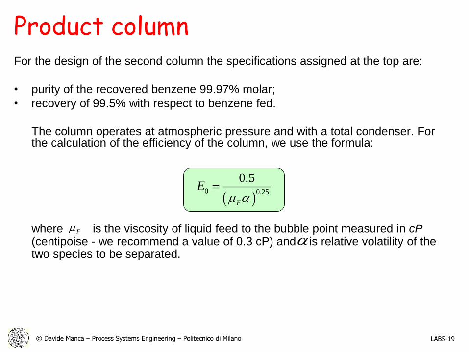
Product columnFor the design of the second column the specifications assigned at the top are:
• purity of the recovered benzene 99.97% molar;
• recovery of 99.5% with respect to benzene fed.
The column operates at atmospheric pressure and with a total condenser. For the calculation of the efficiency of the column, we use the formula:
where is the viscosity of liquid feed to the bubble point measured in cP(centipoise - we recommend a value of 0.3 cP) and is relative volatility of the two species to be separated.
F
0 0.25
0.5
F
E
LAB5-19

© Davide Manca – Process Systems Engineering – Politecnico di Milano
Product columnThe design of the product column should be entirely done by the student.
The column should be sized by methods other than McCabe and Thiele because it
is not ideal (e.g. Fenske). It is possible to assume a reflux ratio 1.3 times the
minimum ratio.
To choose the number of trays you have to analyze the temperature and
concentration profiles in column (Output - Generate Plot).
The choice will have to take into account that the lowering of number of trays
involves an increase in the duties.
LAB5-20

© Davide Manca – Process Systems Engineering – Politecnico di Milano
Recycling columnYou are required to recover:
• Top product at 99.5% of the toluene fed;
• Bottom product at 99.5% of biphenyl fed.
The real stages are 20 (18 trays) and the “feed tray” is at 14th stage
(numbered from the top). The efficiency of the column is computed with the
formula previously presented.
Additional data:
• head pressure of 1 atm;
• (Indicative: it is advisable to operate with a recycle ratio of not less than 1.5
times the minimum. Estimated reflux ratio L/D = 0.012).
LAB5-21

© Davide Manca – Process Systems Engineering – Politecnico di Milano
Efficiency conceptThe efficiency is related to the mass transfer, which depends on the geometry and
the design of the trays by the flow rate, from the paths followed by the currents,
from the composition.
You can define:
The efficiency of the column:
Basically you assign a unique value of efficiency to the entire column. Is it okay for
a preliminary design? In fact the concept of efficiency is too articulated in order to
be confined to a single parameter for the whole column.
id
real
N
N
LAB5-22

© Davide Manca – Process Systems Engineering – Politecnico di Milano
Concept of efficiency
• The “local efficiency”: identifies the efficiency of a point on the plate, good for
large diameter columns.
• The “tray efficiency” : also known as the Murphree efficiency. The calculation
assumes a perfect mixing on the plate. For multi-component mixtures must be
assigned an efficiency of tray for each of the components themselves.
LAB5-23
© Davide Manca – Process Systems Engineering – Politecnico di Milano
Suggestions
• You have to assess if it is possible to operate with only two columns to separate:
the benzene in the top in the first and in the second biphenyl in the bottom,
recycling the residual toluene fraction. Specify the reasons for the impossibility of
such a solution.
• Identify and design the best separation section.
• Perform the short-cut design of the column of the product (NOT using UniSim) in
order to determine the minimal number of plates and the real one, and the
optimal feed point.
LAB5-24