
Executive Summary Batakundi HPP (27-11-2014) -...
24
96 MW Batakundi Hydropower Project Feasibility Study Report Executive Summary DOCUMENTS / REPORT CONTROL FORM Project Name Draft Feasibility Study of Batakundi Hydropower Project Report Name Executive Summary Project Number 218 Report for: Pakhtunkhwa Energy Development Organization PREPARATION, REVIEW AND AUTHORIZATION Revision # Date Prepared by Reviewed by Approved for Issue by 01 02 18-Sep-2014 08-Oct-2014 Ilyas Ahmad Arshad Fayaz Dr. Habib-ur-Rehman Muhammad Inam M.D Zulfi Syed Karamat Ali Dr. Ramzan Chaudhry Arshad Munir Dr. Tahir Masood Hasnain Reza Mirza ISSUE REGISTER: Distribution List Date Issued Number of Copies Pakhtunkhwa Energy Development Organization 10-Oct-2014 10 No. MAES, ILF, BA, 10-Oct-2014 1 No (each) by e-mail Project File 10-Oct-2014 1 No PROJECT OFFICE: Mirza Associates Engineering Services (Pvt.) Ltd. (Lead Consultant) H. No. 105, Street No. 07, Sector - H-3, Phase II, Hayatabad, Peshawar. Tel: +92-91-5813459 E-mail: [email protected] URL: www.maes.com.pk
Transcript of Executive Summary Batakundi HPP (27-11-2014) -...

96 MW Batakundi Hydropower ProjectFeasibility Study ReportExecutive Summary
DOCUMENTS / REPORT CONTROL FORM
Project Name Draft Feasibility Study of Batakundi Hydropower Project
Report Name Executive Summary
Project Number 218
Report for: Pakhtunkhwa Energy Development Organization
PREPARATION, REVIEW AND AUTHORIZATION
Revision # Date Prepared by Reviewed byApproved for
Issue by
01
02
18-Sep-2014
08-Oct-2014
Ilyas AhmadArshad FayazDr. Habib-ur-RehmanMuhammad InamM.D ZulfiSyed Karamat AliDr. Ramzan Chaudhry
Arshad Munir
Dr. Tahir Masood
Hasnain Reza Mirza
ISSUE REGISTER:
Distribution List Date Issued Number of Copies
Pakhtunkhwa Energy Development Organization 10-Oct-2014 10 No.
MAES, ILF, BA, 10-Oct-2014 1 No (each) by e-mail
Project File 10-Oct-2014 1 No
PROJECT OFFICE:
Mirza Associates Engineering Services (Pvt.) Ltd. (Lead Consultant)
H. No. 105, Street No. 07, Sector - H-3, Phase II,
Hayatabad, Peshawar.
Tel: +92-91-5813459
E-mail: [email protected]
URL: www.maes.com.pk


96 MW Batakundi Hydropower ProjectFeasibility Study ReportExecutive Summary
LIST OF VOLUMES
EXECUTIVE SUMMARY
VOLUME - 1 MAIN REPORT
VOLUME - 2 DESIGN CRITERIA (CIVIL, ELECTRICAL, MECHANICAL)
VOLUME - 3 TOPOGRAPHIC AND HYDROGRAPHIC SURVEYS
VOLUME - 4 HYDROLOGY AND SEDIMENTATION STUDIES
Vol. 4-1/2 - Report
Vol. 4-2/2 - Annexures
VOLUME - 5 NEOTECTONICS AND SEISMIC HAZARD STUDIES
VOLUME - 6 GEOLOGICAL AND GEOTECHNICAL STUDIES
Vol. 6-1/6 - General
Vol. 6-2/6 - Dam and Intake Structures
Vol. 6-3/6 - Dam (Annexures)
Vol. 6-4/6 - Headrace Tunnel
Vol. 6-5/6 - Powerhouse and Outlet Structures
Vol. 6-6/6 - Powerhouse (Annexures)
VOLUME - 7 CIVIL, DAM & OTHER HYDRAULIC STRUCTURES
VOLUME - 8 POWER TRANSMISSION STUDIES
VOLUME - 9 ENVIRONMENTAL AND SOCIAL IMPACT ASSESSMENT
Vol. 9-1/2 - Report
Vol. 9-2/2 - Annexure
VOLUME - 10 PROJECT DRAWINGS


96 MW Batakundi Hydropower ProjectFeasibility Study ReportExecutive Summary TOC-1
TABLE OF CONTENTS
Sr. No Description Page No.
1 INTRODUCTION..............................................................................................1
2 DESIGN CRITERIA (CIVIL, ELECTRICAL AND MECHANICAL) ....................4
3 TOPOGRAPHIC AND HYDROGRAPHIC SURVEYS ......................................4
4 HYDROLOGY AND SEDIMENTATION STUDIES ...........................................5
5 NEOTECTONICS AND SEISMIC HAZARD STUDIES.....................................5
5.1 SEISMIC DESIGN PARAMETERS BASED ON DETERMINISTIC SEISMICHAZARD ASSESSMENT (DSHA) APPROACH................................................5
5.2 SEISMIC DESIGN PARAMETERS BASED ON PROBABILISTIC SEISMICHAZARD ASSESSMENT (PSHA) APPROACH................................................6
6 GEOLOGICAL AND GEOTECHNICAL STUDIES ...........................................6
7 PROJECT LAYOUT STUDIES.........................................................................7
8 PROJECT SIZING AND POWER POTENTIAL STUDIES ...............................7
9 CIVIL, DAM AND OTHER HYDRAULIC STRUCTURES .................................8
9.1 MAIN DAM .......................................................................................................9
9.2 RIVER DIVERSION SCHEME..........................................................................9
9.3 POWER INTAKE STRUCTURE .......................................................................9
9.4 LOW PRESSURE HEADRACE TUNNEL.........................................................9
9.5 PRESSURE TUNNEL ....................................................................................10
9.6 TAILRACE TUNNEL.......................................................................................10
9.7 HEAD LOSSES IN THE CONDUIT SYSTEM .................................................10
9.8 SURGE TANK ................................................................................................10
9.9 POWER COMPLEX .......................................................................................10
9.9.1 Multi Storied Transformer Cavern...................................................................10
9.9.2 Access Tunnel................................................................................................11
9.9.3 Cable and Ventilation Tunnel..........................................................................11
10 ELECTRICAL EQUIPMENT STUDIES ..........................................................11
11 REMOTE CONTROL SYSTEM STUDIES......................................................11
12 POWER TRANSMISSION STUDIES .............................................................11
13 ENVIRONMENTAL AND SOCIAL IMPACT ASSESSMENT..........................12
14 COST ESTIMATES ........................................................................................13
15 PROJECT IMPLEMENTATION AND CONSTRUCTION PLANNING ............15
16 ECONOMIC AND FINANCIAL ANALYSIS ....................................................16


96 MW Batakundi Hydropower ProjectFeasibility Study ReportExecutive Summary Page - 1
EXECUTIVE SUMMARY
1 INTRODUCTION
Batakundi Hydropower Project (HPP) is one of the series of hydropowerdevelopment projects launched by Pakhtunkhwa Energy DevelopmentOrganization (PEDO), Government of Khyber Pakhtunkhwa (KP). The objective ofthe proposed hydropower scheme is to generate and add cheap energy to thesystem in order to meet the current shortfall and increasing demand of electricityin the region through economical and sustainable means.
Batakundi HPP was originally identified under the study “Identification ofHydropower Potential in Kaghan Valley”by the then Sarhad Hydel DevelopmentOrganization (SHYDO) (now called PEDO) with the technical collaboration of theGerman Agency for Technical Cooperation (GTZ).The project envisaged a 60 mhigh dam with a 4.5 km long headrace tunnel and an underground powerhouse onthe right bank of Kunhar River. The dam axis was, identified 8 km upstream ofBatakundi Village, headrace tunnel on the right bank and the powerhouse nearDhadar nullah confluence with Kunhar River.
PEDO carried out ICB in 2011 for the selection of Consultant to carry out detailedFeasibility Study of the Project. As a result of the competitive bidding, theConsortium of Consultants led by Mirza Associates Engineering Services (Pvt.)Ltd. (MAES) was selected for implementation of the Feasibility Study of BatakundiHPP. The letter of commencement was issued on June 13, 2012 for pre-feasibiltystudy,which was later converted to the feasibility study. The Consultants carriedout the services for two years i.e. June 2012 to October 2014 and have completeda bankable Feasibility Study of the project.
The study has resulted in a project size of 96 MW with an excellent economic rateof return. Table - 1 presents the salient features of the project. The BatakundiHPP is proposed to be located on Kunhar River, with its powerhouse locatedabout 1 (One) km downstream of Batakundi Village, which falls in DistrictMansehra of KP Province. The project area is accessible by road from Rawalpindi/ Islamabad through Abbotabad, Mansehra and Balakot (Figure 1)
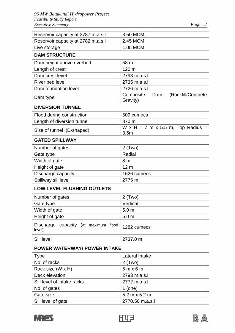
Table - 1: Salient Features of the Project
HYDROLOGY (DESIGN FLOWS)
Catchment area at dam site 720 km2
Mean annual flow 32 cumecs
Design discharge 52.0 cumecs
Design flood (10,000 Year Flood) 2244 cumecs
RESERVOIR
Reservoir length 2080 m
Reservoir area 0.235 km2
Maximum flood level 2790 m.a.s.l
Max. reservoir operating level 2787 m.a.s.l
Min. reservoir operating level 2782 m.a.s.l
96 MW Batakundi Hydropower ProjectFeasibility Study ReportExecutive Summary Page - 2
Reservoir capacity at 2787 m.a.s.l 3.50 MCM
Reservoir capacity at 2782 m.a.s.l 2.45 MCM
Live storage 1.05 MCM
DAM STRUCTURE
Dam height above riverbed 58 m
Length of crest 120 m
Dam crest level 2793 m.a.s.l
River bed level 2735 m.a.s.l
Dam foundation level 2726 m.a.s.l
Dam typeComposite Dam (Rockfill/ConcreteGravity)
DIVERSION TUNNEL
Flood during construction 509 cumecs
Length of diversion tunnel 370 m
Size of tunnel (D-shaped)W x H = 7 m x 5.5 m, Top Radius =3.5m
GATED SPILLWAY
Number of gates 2 (Two)
Gate type Radial
Width of gate 8 m
Height of gate 12 m
Discharge capacity 1626 cumecs
Spillway sill level 2775 m
LOW LEVEL FLUSHING OUTLETS
Number of gates 2 (Two)
Gate type Vertical
Width of gate 5.0 m
Height of gate 5.0 m
Discharge capacity (at maximum floodlevel)
1282 cumecs
Sill level 2737.0 m
POWER WATERWAY/ POWER INTAKE
Type Lateral Intake
No. of racks 2 (Two)
Rack size (W x H) 5 m x 6 m
Deck elevation 2793 m.a.s.l
SilI level of intake racks 2772 m.a.s.l
No. of gates 1 (one)
Gate size 5.2 m x 5.2 m
Sill level of gate 2770.50 m.a.s.l
96 MW Batakundi Hydropower ProjectFeasibility Study ReportExecutive Summary Page - 3
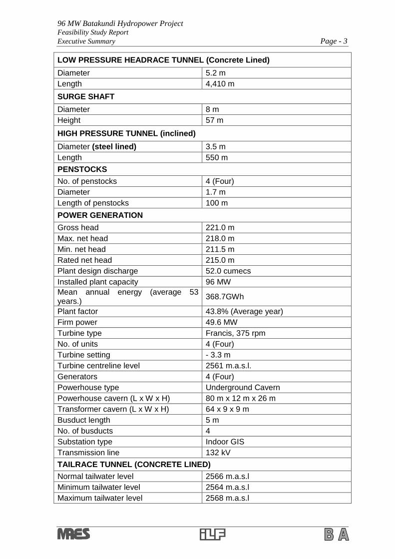
LOW PRESSURE HEADRACE TUNNEL (Concrete Lined)
Diameter 5.2 m
Length 4,410 m
SURGE SHAFT
Diameter 8 m
Height 57 m
HIGH PRESSURE TUNNEL (inclined)
Diameter (steel lined) 3.5 m
Length 550 m
PENSTOCKS
No. of penstocks 4 (Four)
Diameter 1.7 m
Length of penstocks 100 m
POWER GENERATION
Gross head 221.0 m
Max. net head 218.0 m
Min. net head 211.5 m
Rated net head 215.0 m
Plant design discharge 52.0 cumecs
Installed plant capacity 96 MW
Mean annual energy (average 53years.)
368.7GWh
Plant factor 43.8% (Average year)
Firm power 49.6 MW
Turbine type Francis, 375 rpm
No. of units 4 (Four)
Turbine setting - 3.3 m
Turbine centreline level 2561 m.a.s.l.
Generators 4 (Four)
Powerhouse type Underground Cavern
Powerhouse cavern (L x W x H) 80 m x 12 m x 26 m
Transformer cavern (L x W x H) 64 x 9 x 9 m
Busduct length 5 m
No. of busducts 4
Substation type Indoor GIS
Transmission line 132 kV
TAILRACE TUNNEL (CONCRETE LINED)
Normal tailwater level 2566 m.a.s.l
Minimum tailwater level 2564 m.a.s.l
Maximum tailwater level 2568 m.a.s.l

96 MW Batakundi Hydropower ProjectFeasibility Study ReportExecutive Summary Page - 4
Width of tunnel 5.0 m
Length of tailrace tunnel 110 m
Outlet sill level 2564 m.a.s.l
Stoplog operation platform level 2574 m.a.s.l
This Feasibility Study Report consists of a Main Report (Volume-1) and nine (9)supporting volumes. The Main Report consists of eighteen (18) sectionscompletely covering all aspects of the project at feasibility study level, whereas thenine(9) volumes present details of the studies, field data, drawings and otherrequired information related to different sections of the Main Report.
2 DESIGN CRITERIA (CIVIL, ELECTRICAL AND MECHANICAL)
A design criteria is necessary for setting out the guidelines / basis of all thedesigns and field operations necessary for preparing the Feasibility Report. Thedesign criteria document for Civil, Electrical and Mechanical works has beenprepared, which covers all aspects of the design and field operations.
3 TOPOGRAPHIC AND HYDROGRAPHIC SURVEYS
The topographic survey and mapping have been carried out for all thecomponents of the project. The tasks include establishment of datum and groundcontrol points (GCPs), detailed topographic ground survey at the sites for dam,reservoir area, tunnels, powerhouse, tailrace outlet; and the river valley crosssections at the dam and powerhouse areas. The work has been done mainly byconventional survey aided by SPOT-5 satellite imagery.
Topographic surveys for the project features have been carried out at thefollowing scales:
a. Reservoir area, Headrace Tunnel / Channels, Access Roads 1:2000
b. Dam Site and Intake Area 1:500
c. Surge Tank, Pressure Tunnel / Penstock,Powerhouse and Tailrace 1:1000
d. Project Layout 1:25,000
The survey has been carried out in local grid system of Survey of Pakistan (SOP)using the benchmark at Batrasi as datum. All survey work has been duly verifiedwith dual frequency GPS survey instruments and found to be correct.
The terrestrial survey has been carried-out for the two (2) alternative projectlayouts conceived and selected for the field work at the Inception Stage andcovers all the above mentioned project components.
For the inaccessible areas of the tunnel alignments, topographic maps have beendeveloped with the help of high resolution Digital Elevation Models (DEMs), ortho-rectified with ground survey.
Hydrographic survey was carried out and longitudinal profiles of the relevantstretch of Kunhar River were prepared.
96 MW Batakundi Hydropower ProjectFeasibility Study ReportExecutive Summary Page - 5
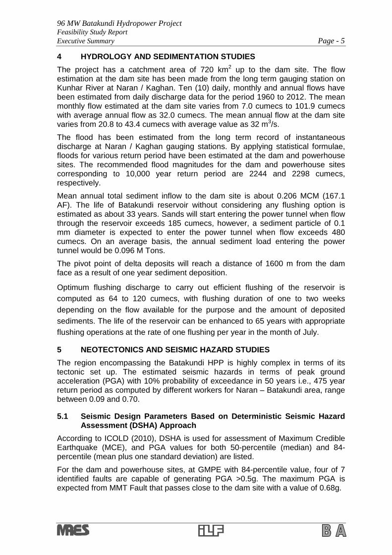
4 HYDROLOGY AND SEDIMENTATION STUDIES
The project has a catchment area of 720 km2 up to the dam site. The flowestimation at the dam site has been made from the long term gauging station onKunhar River at Naran / Kaghan. Ten (10) daily, monthly and annual flows havebeen estimated from daily discharge data for the period 1960 to 2012. The meanmonthly flow estimated at the dam site varies from 7.0 cumecs to 101.9 cumecswith average annual flow as 32.0 cumecs. The mean annual flow at the dam sitevaries from 20.8 to 43.4 cumecs with average value as 32 m3/s.
The flood has been estimated from the long term record of instantaneousdischarge at Naran / Kaghan gauging stations. By applying statistical formulae,floods for various return period have been estimated at the dam and powerhousesites. The recommended flood magnitudes for the dam and powerhouse sitescorresponding to 10,000 year return period are 2244 and 2298 cumecs,respectively.
Mean annual total sediment inflow to the dam site is about 0.206 MCM (167.1AF). The life of Batakundi reservoir without considering any flushing option isestimated as about 33 years. Sands will start entering the power tunnel when flowthrough the reservoir exceeds 185 cumecs, however, a sediment particle of 0.1mm diameter is expected to enter the power tunnel when flow exceeds 480cumecs. On an average basis, the annual sediment load entering the powertunnel would be 0.096 M Tons.
The pivot point of delta deposits will reach a distance of 1600 m from the damface as a result of one year sediment deposition.
Optimum flushing discharge to carry out efficient flushing of the reservoir is
computed as 64 to 120 cumecs, with flushing duration of one to two weeks
depending on the flow available for the purpose and the amount of deposited
sediments. The life of the reservoir can be enhanced to 65 years with appropriate
flushing operations at the rate of one flushing per year in the month of July.
5 NEOTECTONICS AND SEISMIC HAZARD STUDIES
The region encompassing the Batakundi HPP is highly complex in terms of itstectonic set up. The estimated seismic hazards in terms of peak groundacceleration (PGA) with 10% probability of exceedance in 50 years i.e., 475 yearreturn period as computed by different workers for Naran –Batakundi area, rangebetween 0.09 and 0.70.
5.1 Seismic Design Parameters Based on Deterministic Seismic HazardAssessment (DSHA) Approach
According to ICOLD (2010), DSHA is used for assessment of Maximum CredibleEarthquake (MCE), and PGA values for both 50-percentile (median) and 84-percentile (mean plus one standard deviation) are listed.
For the dam and powerhouse sites, at GMPE with 84-percentile value, four of 7identified faults are capable of generating PGA >0.5g. The maximum PGA isexpected from MMT Fault that passes close to the dam site with a value of 0.68g.

96 MW Batakundi Hydropower ProjectFeasibility Study ReportExecutive Summary Page - 6
5.2 Seismic Design Parameters Based on Probabilistic Seismic HazardAssessment (PSHA) Approach
Ground motion parameters for return periods from 150 to 10,000 years forappropriate selection as the MDE parameters corresponding to PGAs of 0.33 to0.68g for the dam and the powerhouse sites have been included. However,considering the seismic history of the Naran-Batakundi area, it is recommendedthat the ground-motion parameters for the MDE may be selected for 1000 yearreturn period as a minimum and 10,000 year as the maximum.
The OBE is expected to occur during the lifetime of the structure. No damage orloss of service is allowed. It has a probability of occurrence of about 50% duringthe service life of 100 years. The return period is taken as 150 years (ICOLD2010). The OBE ground motion parameters are estimated based on PSHA. Forthe project, 150 year return period has been recommended for selection of theOBE ground-motion parameters, which corresponds to 0.15g for the dam site andthe powerhouse sites.
6 GEOLOGICAL AND GEOTECHNICAL STUDIES
The field work for the project comprised surface geological mapping includingscan line surveys, geophysical survey using seismic refraction method, drilling ofboreholes, coring and logging, performance of permeability and water pressuretests, and excavation of test pits at potential construction material sources.
Sedimentary and metamorphic rocks are exposed in the project area. Thefollowing two formations / rock units are encountered along the dam site,headrace tunnel and powerhouse area of the Batakundi HPP, which belong toSharda Group.
Burawai Gneisses (Bans Pelite)
Dadar Migmatites
A total of 08 scan line surveys and 06 profiles of seismic refraction survey, werecarried out at the dam / intake area, headrace tunnel, powerhouse etc.
For collection of the soil / rock samples and to perform in-situ tests, 21 boreholeswere drilled at the proposed structure locations, with total drilling depth of 1414 m.
Test pits were also excavated at various structure locations for investigation andverification of the extent of overburden and physical inspection of its nature at thesite. Some other pits were excavated in prospective borrow areas for evaluation ofthe construction materials i.e. coarse as well as fine aggregate, rockfill andcohesive material.
Suitability of the potential construction material sources has been examinedthrough laboratory testing of representative samples.
On the basis of observed RQD values, the bedrock can be classified as “VeryPoor to Excellent”with a very wide range of core recovery.
In the light of data collected and analyses carried out, the rock mass designparameters were determined for various components of the project, and used forevaluating the stability as well as foundation design parameters for the variousstructures. For the underground structures i.e. headrace tunnel, surge shaft,

96 MW Batakundi Hydropower ProjectFeasibility Study ReportExecutive Summary Page - 7
powerhouse caverns and tailrace tunnel, stability analyses and design of supportsystems have been carried out.
7 PROJECT LAYOUT STUDIES
The Consultants identified alternative dam and powerhouse sites in addition to thepreviously identified sites by GTZ-SHYDO (now PEDO) (Figure 2). The selectedproject layout is on the right bank of Kunhar River with the geodetic co-ordinatesof the dam and powerhouse sites as follows:
Site Latitude Longitude
Dam 340 –55’–07” 730 –48’–23”
Powerhouse 340 –56’–20” 730 –46’–24”
Based on the parameters for screening viz: good topographical, hydrological andgeological conditions, minimal environmental issue etc, the dam site selected islocated 4.5 km upstream of Batakundi Village. At the selected dam site, the valleysections are narrow at the upstream cofferdam, downstream cofferdam, diversiontunnel, main dam, plunge pool and power intake area.
The selected powerhouse site is near Dhadar nullah confluence and BatakundiVillage. The topographic and geological conditions at the powerhouse site favouran underground powerhouse. Necessary investigations have been carried out atthe dam, powerhouse and headrace tunnel alignment to confirm the technicalviability of project layout.
The previously identified project layout by GTZ-SHYDO (now PEDO) has beenfound technically un-feasible due to poor geological conditions at the proposeddam site D-1. The geological conditions at the dam site D-1 do not favour theplacement of the main dam and allied structures for dam construction, as well asthe power intake for the headrace tunnel.
The alternative Project layout has sound geological conditions at the dam site D-2,headrace tunnel, powerhouse and tailrace outlet areas. The sound geologicalconditions and promising topography for the project area and the availability oflong historical record of flows at Batakundi give the confidence to improve thedesign discharge and installed capacity of Batakundi Hydropower Project.
The selected layout has relatively smaller dam, shorter low pressure tunnel, and areservoir with adequate storage for daily peaking. The dam, reservoir andpowerhouse sites have minimum environmental issues in terms of landacquisition, people’s resettlement, road realignment etc (Figure 2).
8 PROJECT SIZING AND POWER POTENTIAL STUDIES
For the selected project layout, optimization of capacity, diameters of headracetunnel and pressure shaft have been performed. For capacity optimization, longrun marginal power and energy prices are used to estimate benefits for variousdesign discharges. Considering the flows in the river at the dam site, a designdischarge range from 24 to 76 cumecs with incremental intervals of 4 cumecs hasbeen considered to determine the capacity, energy, benefits and costing. For eachdischarge, preliminary costs of the project have been estimated. Benefits havebeen estimated for each considered design discharge by computing power and

96 MW Batakundi Hydropower ProjectFeasibility Study ReportExecutive Summary Page - 8
energy on monthly basis. Corresponding net present value (NPV) calculationswere also performed. The capacity with the highest NPV value has been selectedas the installed capacity.
For optimization of the design of headrace tunnel and pressure tunnel, differentdiameters were assumed. The diameter having the lowest sum of incremental andenergy loss costs was taken as the optimum. With sound and good geologicalconditions for the headrace tunnel, concrete lining is considered adequate and anoptimized diameter of 5.2 m has been selected. Similarly, steel lining for theinclined pressure tunnel has been considered for which 3.5 m diameter isoptimized for design discharge of 52 cumecs.
For optimization of plant capacity, run-of-the river and peaking options wereevaluated and sensitivity analysis performed. It has been found that 4-hour peakwith design discharge of 52 cumecs and plant capacity of 68 MW will be theoptimum. The maximum and minimum reservoir levels were assumed as 2787.0and 2782.0 m.a.s.l. respectively.
A residual flow of 0.70 cumecs in winter months and 1.5 cumecs in summermonths has been assumed to estimate the power and energy on 10 daily basis.Efficiencies of 91.0%, 97.0% and 99% have been used for the turbines,generators and transformers respectively. The head loss has been estimated as9.70 m for the design discharge of 52 cumecs.
During the low flow periods, the live storage is used to store water during off peakhours to improve the flows for power generation in the peak hours. It has beenestimated that 1.05 MCM storage would provide additional flows in 4 peak hours.
The tailwater elevation varies from 2564 to 2568 m.a.s.l, and the net head variesbetween 211.5 to 218.0 m with an average value of 215.0 m. For the designdischarge of 52 cumecs and net head of 215.0 m, the optimum installed capacitywould be 96 MW with average mean annual energy of 368.7 GWh, at a plantfactor of 43.8%. The calculated annual energy, for the years 2012 wet year, 1983average year and 2006 dry year, is 505.56,364.06 and 288.9 GWh respectively.
9 CIVIL, DAM AND OTHER HYDRAULIC STRUCTURES
Hydraulic analysis and sizing of the project structures has been carried out to thefeasibility design level for the following structures:
a. Main Dam
b. Power intake structure on the right bank of the river
c. Low pressure headrace tunnel
d. Surge tank
e. Steel lined high pressure tunnel
f. High pressure penstocks
g. Underground powerhouse with transformer cavern
h. Free-flow tailrace tunnel

96 MW Batakundi Hydropower ProjectFeasibility Study ReportExecutive Summary Page - 9
9.1 Main Dam
At Batakundi dam axis, the right abutment has exposed rock while the geology atleft abutment is weeker with a rock wedge avilable to an elevation of 2760 ma.s.l.,and above this rock wedge the abutment contains glacial deposits.
Considering the geology at dam axis, a composite dam has been planned for theproject. The dam at the right abutment and across the river width will be aconcrete gravity dam while at the left abutment, it will be a concrete core rockfilldam (Figure 3).
A two bay gated spillway each of H x W = 12 m x 8 m has been provided with thecrest level at 2775 m.a.s.l., two low level outlets each of H x W = 5 m x 5 m havebeen set with crest level at 2737 m.a.s.l.
The gated spillway has a dischrge capacity 1626 m3/s which is more than 1:1000Yflood. PMF (1:10,000Y flood) will be discharged using a combination of gatedspillways and low level outlets. In n-1 hydraulic condition i.e. with one spillwayinoperative, the combination will pass PMF with reservoir level below theMaximum Flood Level i.e. 2790 m.a.s.l.
Low Level Oultlets (LLOs) have a discharge capacity of 1282 m3/s. Thsese outletswill also be used for annual sediment flushing from the reservoir. The river bedlevel at the dam axis is 2735 m.a.s.l. and the bedrock is encountered at EL. 2727m.a.s.l. Height of the main dam from the river bed is 58 m.
9.2 River Diversion Scheme
The river diversion works consist of the following components:
a. Rockfill cofferdam with impervious core and crest level at 2751 m.a.s.l at theupstream side.
b. Rockfill cofferdam with impervious core and crest level at 2747 m.a.s.l at thedownstream side.
c. A D-shaped diversion tunnel with rectangular section W x H = 7 m x 5.5 mand arch section of 3.5 m radius having a length of 370 m has beenproposed to direct the flows for the dam construction area.
9.3 Power Intake Structure
A 2-bay intake structure with trash racks has been proposed for passing thedesign discharge. A 5.2 m wide 5.2 m high, control gate equipped with upstreamsealing has been provided.
9.4 Low Pressure Headrace Tunnel
Headrace tunnel has been optimized by considering different diameters for thedesign discharge with the following parameters:
a. Manning- Stickler coefficient (shotcrete) 60
b. Tunnel slope 0.11 %
c. Shotcrete lining thickness 0.10-0.3 m (as per conditions)
d. Concrete lining 0.3 m

96 MW Batakundi Hydropower ProjectFeasibility Study ReportExecutive Summary Page - 10
The optimized diameter. of low pressure headrace tunnel is 5.2 m and it is 4410 mlong.
9.5 Pressure Tunnel
Pressure tunnel is steel lined and has the following dimensions.
Diameter 3.5m
Length 550 m
9.6 Tailrace Tunnel
The data of the main concrete lined tailrace tunnel is as follows:
Total Length 110 m
Cross section type ‘D’shaped
Width 5.0 m
Height 4.5 m
9.7 Head Losses in the Conduit System
The calculation results of the head loss of the conduit system indicated that thetotal head loss in the conduit system is approx. 9.70 m.
9.8 Surge Tank
A circular surge tank having 8.0 m diameter has been provided at the end of lowpressure headrace tunnel. The surge tank is 57.0 m deep starting fromEL.2765.95 m.a.s.l. and rising up to EL.2822.95 m.a.s.l.at the ceiling. Surge tankdiameter throttles to 3.0 m at the junction with headrace tunnel.
9.9 Power Complex
An underground powerhouse has been proposed comprising the followingstructures (Figure 4):
a. Underground Powerhouse Cavern
b. GIS Transformer Cavern
c. Main Access Tunnel
d. Cable and Ventilation Tunnel
The powerhouse cavern is 80 m long, 12.0 m wide and 26 m high from the maininlet valve floor to the arch roof crown.
9.9.1 Multi Storied Transformer Cavern
The main features of the transformer hall cavern (L 64m x W 9.0m x H 9.0m) andthe factors considered in the determination of the layout are:
a. Single phase generator transformers (3 per unit, plus one spare) will beplaced in separate fire-protected enclosures.
b. Transformer transfer facility through rails starting from the unloading bay ofpowerhouse at El: 2570.0 m.a.s.l.
c. Placement of GIS equipment,

96 MW Batakundi Hydropower ProjectFeasibility Study ReportExecutive Summary Page - 11
d. Facility for transfer of the power cable to the cable tunnel.
9.9.2 Access Tunnel
The access tunnel is the main point of entry to the underground powerhousecomplex. It is sized to accommodate two-way dump truck traffic duringconstruction, and to provide the space needed to transport heavy equipment onlow bay loaders or multi-wheeled transporters into the caverns. The largest itemsto be transported will be the generator transformers, the main inlet valves and theturbine spiral casing. A ‘D’shaped access tunnel of 247 m length and size of7.0 m width and 8.6 m height with a slope of 10% is provided.
9.9.3 Cable and Ventilation Tunnel
The cables from the transformer cavern are carried through a 4 m x 4 m cabletunnel up to the proposed 132 KV / 11 KV NTDC substation. This tunnel will alsobe used for ventilating the transformer and powerhouse caverns. Afterconstruction of the powerhouse roof, the construction adit will be used to ventilatethe powerhouse and connect with the cable tunnel.
10 ELECTRICAL EQUIPMENT STUDIES
This section includes, specifications of generators; cooling and heating system;excitation system; fire protection system for generators; generator isolated phasebus; unit step up transformers; 132 kV XLPE cables; station DC and AC auxiliarysupplies; protection equipment; main earthing and lightning protection system;plant control system (PCS); telecommunication; illumination; small power andvideo supervision system.
11 REMOTE CONTROL SYSTEM STUDIES
This section covers, computer supervisory and control system (CSCS) as anoption for remote control of Balakot, Naran and Batakundi HPPs from the centralcontrol room of Balakot HPP; configuration and equipment description of CSCSand organogram for the joint O&M staff required for central operation of the three(3) HPPs.
12 POWER TRANSMISSION STUDIES
The interconnection of the project to evacuate maximum power of 96 MW isenvisaged and studied in detail as follows:
a. According to National Power System Expansion Plan (NPSEP) of NTDC, a
500 kV double circuit (D/C) line will connect Suki Kinari HPP with Aliot S/S,
a switching station located on the right bank of Jhelum River downstream
of Neelum-Jhelum HPP, where Neelum-Jhelum HPP –Gujranwala S/S 500
kV D/C line will also be looped in-out.
b. Batakundi HPP will be connected by looping in-out one circuit of the D/C
line of 500 kV to be constructed from Basha HPP to Aliot that would be
passing near the powerhouse of the project. A double circuit 132 kV line

96 MW Batakundi Hydropower ProjectFeasibility Study ReportExecutive Summary Page - 12
using underground XLPE cables will be laid from Batakundi to Naran 500
kV take-off yard with provision of 500/132 kV extension.
c. The proposed scheme for 500 kV switchyard has double bus-bars of 500
kV with 04 diameters of breaker-and-half scheme.
Detailed load flow, short circuit and transient stability studies have beenconducted for the peak load conditions of June 2020 for the interconnectionscheme, as the plant is expected to be commissioned by the end of year 2019.Load flow analyses reveal that the scheme is adequate to evacuate the maximumpower of 300 MW under normal and N-1 contingency conditions.
The transmission system is based on an interconnection study covering detailedload flow as per June 2020 forecast, short circuit analysis and transient stabilityanalysis; configuration and equipment description of 132 kV GIS substation; 132kV XLPE power cables ; protection and metering equipment.
The transient stability analysis of the proposed scheme of interconnection hasbeen carried out. The stability check for the worst case of 3 phase fault right onthe 500 kV bus bar of the substation followed by the final trip of 500 kV circuitsemanating from this substation, has been performed for fault clearing of 5 cycles(100 ms), as understood to be the normal fault clearing time of 500 kV protectionsystem. The system has been found to be strong enough to stay stable andrecovers with fast damping, and therefore passed the transient stability checks.
The proposed scheme of interconnection has no technical constraints orproblems, and is accordingly recommended to be adopted.
13 ENVIRONMENTAL AND SOCIAL IMPACT ASSESSMENT
The broad objective of ESIA studies is to fulfil the mandatory legal requirment toassess the beneficial and adverse impacts of the project implementation on theenvironment including physical, biological and socio-economic parameters and tomitigate the adverse impacts.
The project area of the reservoir is under, agriculture, range land with some forestand fruit trees, mixed shrubs and rough grasses. There are no industries in andaround the project area; therefore, noise pollution is generally below the EPAlimits. The air quality in the area is also good.
The environmental and ecological water releases downstream of the dam will be0.7 cumecs and 1.5 cumecs in winter and summer respectively. The flora existingin the project as well as the study areas falls under moist sub-tropical pine forestsgenerally called Deodar forests.
Fauna of the tract consists of mammals, reptiles, amphibians and birds. Some ofthe most colorful and beautiful fowls like Monal pheasants and Kaleej are found inthe surrounding mountains. Archaeological / historical sites in the reservoir andpowerhouse areas do not exist.
The population of the project area is a mixture of Punjabi, Kashmiri andPathan.The major language of project area is Urdu, Hindko and Gojri. In theproject area, no proper medical facilities exist. Only one BHU and some privatemedical stores are available in Naran town, located about 17 km away from theBatakundi powerhouse. Majority (78%) of the female respondents also participate

96 MW Batakundi Hydropower ProjectFeasibility Study ReportExecutive Summary Page - 13
in work other than household chores and livelihood earning is the responsibility ofmales.
The reservoir of the project will permanently submerge 89.0 acre land. Out of thisland, 14 acre is irrigated agricultural land whereas 1, 9 and 49 acre land isresidential, forest / grazing and barren respectively. One acre land will beoccupied by the underground powerhouse, tailrace tunnel etc. In addition, area of15 acres will be occupied for staff / residential colony (10 acre in combined colonyin Sanghar village near Balakot HPP powerhouse, and 5 acre in BatakundiVillage).
In the reservoir area, 30 trees are being impacted. There will be no danger tolarge wildlife due to the execution of the project, as they live in forest areas, whichare located at higher altitude.
There will be positive impact on the birds and the fowl communities as a suitablehabitat will be formed for this community with the creation of the reservoir.Construction of the project will result in the creation of job opportunities, betterpotential for business, transport and tourism development.
During construction, environmental monitoring will be done for air quality, noiseand vibration, drinking water quality, sewage effluent, solid waste, explosivematerial used, hazardous / toxic materials and their proper disposal, flora / fauna,excavated material and traffic handling system etc. Due to the construction of theproject, 15 houses are being affected, which will require resettlement orcompensation.
All the owners of the land and land based assets will be resettled or compensatedaccording to the D.C. rates or the rates assessed by the Committee constituted forthis purpose by the D.C. The survey revealed that more than 90 % of theaffectees favored cash compensation. A Grievance Redressal Committee (GRC)is proposed, which will look into all the grievance cases.
The project environmental and resettlement cost amounts to US$ 1.612 million,which is less than 01% of the total project cost. PEDO will be responsible for theoverall implementation of environmental mitigation measures and the RAPthrough its Project Director and field offices, with the collaboration of districtgovernment departments.
14 COST ESTIMATES
The cost estimates for the various project works including InfrastructureDevelopment and Site Installations, Civil, Hydro-Mechanical, Hydraulic Steel,Electrical & Substation, have been prepared. These costs also include estimatesfor Environmental Mitigation Program.
The unit and lump sum prices were adopted after preparing the cost rate analysisfor various items, comparing and escalating the unit prices for certain itemsavailable from other on-going or recently completed similar projects. Table - 2presents summary of the cost estimates together with the phasing of yearly cashflow for the proposed five (5) year construction period.

96 MW Batakundi Hydropower ProjectFeasibility Study ReportExecutive Summary Page - 14
Table - 2: Summary of Cost Estimates of Project
Sr.No
DescriptionTotalCost
M. US $Year 1 Year 2 Year 3 Year 4 Year 5
AInfrastructure Development,Mitigation and Preparatoryworks
1Mobilization andDemobilization 4.902 4.902
2
Infrastructure & Technicalfacilities including AccessRoads, Water supply &Drainage and Power supply toResidential colonies at Damand Powerhouse sites
1.980 1.980
3Camps and Housing DuringConstruction 0.581 0.581
4Land Acquisition andEnvironmental MitigationMeasures
1.612 1.612
5Reservoir Slope Stabilizationand Construction DifficultiesCosts
1.200 1.200
Sub Total A 10.275 10.275
B Civil Works
1Coffer Dams and DiversionTunnel 3.559 1.779 1.779 0.000 0.000 0.000
2Dam and Plunge poolExcavation 27.365 0.000 8.209 13.682 5.473 0.000
3 Power Intake 2.984 0.000 2.089 0.895 0.000 0.000
4 Low Pressure Headrace Tunnel 20.716 2.072 6.215 6.215 4.143 2.072
5 Surge Shaft 1.057 0.000 0.211 0.846 0.000 0.000
6 Pressure Tunnel 1.705 0.000 0.341 1.364 0.000 0.000
8 Penstocks 0.130 0.000 0.026 0.104 0.000 0.000
9 Powerhouse 15.171 0.000 3.034 4.551 4.551 3.034
10 Tailrace Tunnel 0.762 0.000 0.381 0.381 0.000 0.000
Sub Total B 73.450 22.286 28.039 14.168 5.106 14.450
C HSS, Mechanical and

96 MW Batakundi Hydropower ProjectFeasibility Study ReportExecutive Summary Page - 15
Sr.No
DescriptionTotalCost
M. US $Year 1 Year 2 Year 3 Year 4 Year 5
Electrical Works
1 Hydraulic Steel Structures 16.777 0.000 8.389 8.389 0.000 0.000
2 Powerhouse Mechanical Works 24.569 0.000 4.914 9.828 7.371 2.457
3 Powerhouse Electrical Works 13.271 0.000 2.654 5.309 3.981 1.327
4 Switchyard Works 6.597 0.000 0.000 0.000 3.299 3.299
5 Transportation 2.800 0.000 0.477 0.954 0.923 0.446
Sub Total C 64.015 0.000 16.434 24.479 15.574 7.529
Sub Total A+B+C 147.739 14.126 38.720 52.518 29.741 12.635
DDesign, Tender Documents,Engineering and SupervisionConsultancy Costs @ 7%,
10.342 0.141 0.387 0.525 0.297 0.126
E Contingencies @ 5% 7.387 0.706 1.936 2.626 1.487 0.632
F
Miscellaneous (Insurance,Performance Bonds andWorkmen Compensation etc.)@ 2%
2.955 0.283 0.774 1.050 0.595 0.253
GDuties @ 5% of EquipmentCost 2.755 0.000 0.718 1.059 0.659 0.319
H EPC BASE COST 171.178 15.256 42.535 57.778 32.780 13.964
Client Expenses, Administrationand Legal Costs @ 5% 8.559 0.763 2.127 2.889 1.639 0.698
Allowance for Greater Risk andUncertainties @ 2% 3.424 0.305 0.851 1.156 0.656 0.279
PROJECT BASE COST 183.160 16.324 45.513 61.822 35.075 14.942
Interest During Construction @3% (LIBOR Rate 0.4% andMark up 2.5%)
5.135 0.458 1.276 1.733 0.983 0.419
TOTAL EPC PROJECTCONSTRUCTION COST 188.295 16.782 46.789 63.555 36.058 15.361
15 PROJECT IMPLEMENTATION AND CONSTRUCTION PLANNING
Project implementation period is estimated to be 5 years including pre-construction activities (Figure 5).

96 MW Batakundi Hydropower ProjectFeasibility Study ReportExecutive Summary Page - 16
16 ECONOMIC AND FINANCIAL ANALYSIS
Economic analysis carried out on the basis of consumer surplus indicates that theproposed investment is feasible as the NPV, at a discount rate of 12%, is310 M-US$ and the IRR is 27%.
Economics of the project was verified on the basis of benefits quantified on thelong run marginal costs (LRMC) of capacity, peak energy and off peak energy at500 KV level. The NPV at 12% discount rate is 269 M. US $ whereas the IRR isabout 26%.
The proposed investment seems to be robust as it is economic even when the
benefits and costs are changed by 20%, even a combined sensitivity with benefits
decreased by 20% and costs increased by 20% still results in a feasible project.
The switching values (estimates of LRMC which are used as benefit parameters)
at which the project is only marginally feasible are: firm capacity 153 $/kW; peak
energy 5.89 c/kWh; and off peak energy 3.68 c/kWh.
The financial analysis of the project has been conducted in accordance with theprocedure laid down by ADB Financial Management and Analysis of projects. Allfinancial costs and benefits have been expressed at early 2013 constant prices.Cost streams used for the purposes of FIRR determination (i.e. capital investment,operation and maintenance, insurance costs and taxes) reflect costs of deliveringthe estimated benefits. The NEPRA approved tariff for Suki Kinari, a high headhydroelectric project, was used to estimate the financial benefits.
The FIRR was calculated as 10.87% (about 22% on nominal basis) for the project.The overall rate compares favorably with the estimated WACC of 6.53%substantiating the financial viability of the project. The project is financiallyfeasible.
Risks have been quantified by the sensitivity analysis. The project is financiallyfeasible on certain assumptions, and based on robust parameters; it will be able towithstand reasonable uncertainties. The tariff at which the project becomesmarginaly feasible is 5.75 c/kWh.
However, the recommended tariff as calculated according to NEPRA/PPIBguidelines is 11.27 US c/KWH as shown in Table - 3 below.
Table - 3: Tariff Calculation
Summary of Tariff Calculations
Years Lev.
Avg. 1-10 11-20 21-30 at 12 %CPP Rs./kW/m 4136 1806 1806EPP Rs./kWh 0.16 0.16 0.16Total Rs./kWh 13.51 5.99 5.99Lev. Rs./kWh at 12% 11.27
In conclusion, the project is both economically and financially feasible. The projectis, however, sensitive to the cost overruns and reduction in tariff. It isrecommended that the project be implemented after tariff determination byNEPRA.

ANNEXURES