
Ex-1.2.5 Experiment Overview (C30C) S.Brezinsek, P.Coad, M.Groth, J.Likonen, G.F.Matthews, M.Rubel,...
20
Ex-1.2.5 Experiment Overview (C30C) S.Brezinsek, P.Coad, M.Groth, J.Likonen, G.F.Matthews, M.Rubel, A.Widdowson and all participants in C30C and JET-EFDA contributors
-
Upload
janis-chapman -
Category
Documents
-
view
213 -
download
0
Transcript of Ex-1.2.5 Experiment Overview (C30C) S.Brezinsek, P.Coad, M.Groth, J.Likonen, G.F.Matthews, M.Rubel,...
Ex-1.2.5Experiment Overview(C30C)
S.Brezinsek, P.Coad, M.Groth, J.Likonen, G.F.Matthews, M.Rubel, A.Widdowsonand all participants in C30C and JET-EFDA contributors
2
OutlineOutline
Goals Plasmaa for C30C experiment AKA Ex-1.2.5 Achievements Information about post-mortem analysis foreseen (back-up)
GoalsRepresentative foot print of material migration in H-Mode with ILWComparison of in-situ techniques with post-mortem analysisDocument the erosion pattern, i.e. Be.Fuel retention with the ILWGas balances vs. fuel content analysis from post-mortem analysisRole of co-deposition vs. implantationEvolution of wall conditions with the ILWPhases to be compared within C28A/monitoring pulse/C30CMini-campaign comparable to ~1 ITER pulse (fluence)

3
Ex-1.2.5 H-modes prior to long term sample removal
Reliable, safe and high repetitive plasma scenario Scenario must be robust and representative for ILW campaigns Use of well developed and exploited plasma scenario
with good confinement (NBI only) Compatible with multiple gas balance studies Minimise disruption risks / avoidance of MGI Plasma duration/repetition optimisation to achieve max fluence
Aim 1000s of divertor flux during heating phase => 1µm deposition at critical surfaces Avoid plasma movement/sweeping to avoid smearing Maximise the divertor time
Plasma scenario Low triangularity: V5_refFT_LT 2.0MA/2.0T/12 MW/6s flattop Identical configuration to first plasma operation and monitoring pulses Minimised Be wall interaction => reduce retention No need for ICRH
3

44
Multi-code approach to track impurity migration
Background plasma provided by EDGE2D/EIRENE and/or Onion-skin model build on Ex 3.1.3 (for low-⇒ config.)
OSM likely to provide better model for divertor conditions than EDGE2D/EIRENE
WALLDYN simulation of migration and mixing – particularly C28a and C30c
ERO for local Be and W migration in the divertor fuel retention; mirror ⇒deposition simulations at KY3 location
3D GAPS for migration into divertor gaps and pumping plenum
ASCOT for 10Be migration from IWGL
Low- V5_REF1FT_LT on stack C
High- HT3R on stack D
5
Initial session to set-up the plasma and characterise it with all available diagnostics prior to C30C (Thursday # 83553-83562)
Local 15N tracer exposure through GIM14 (Monday #83632-83635) 7 sessions with exposure of mirrors on KY3 probe head (cause
impurity influx) 3 AGHS gas balances (25 barl) included in the 2 weeks
Monday (16.7. and 23.7.) and 27.7.2012 (last day) Last day complete AGHS analysis of recovered gas from cryo panel
included Step one LHe Step two LN (possibilities to measure N and ND3 derivates)
Schedule and associated experiments
6
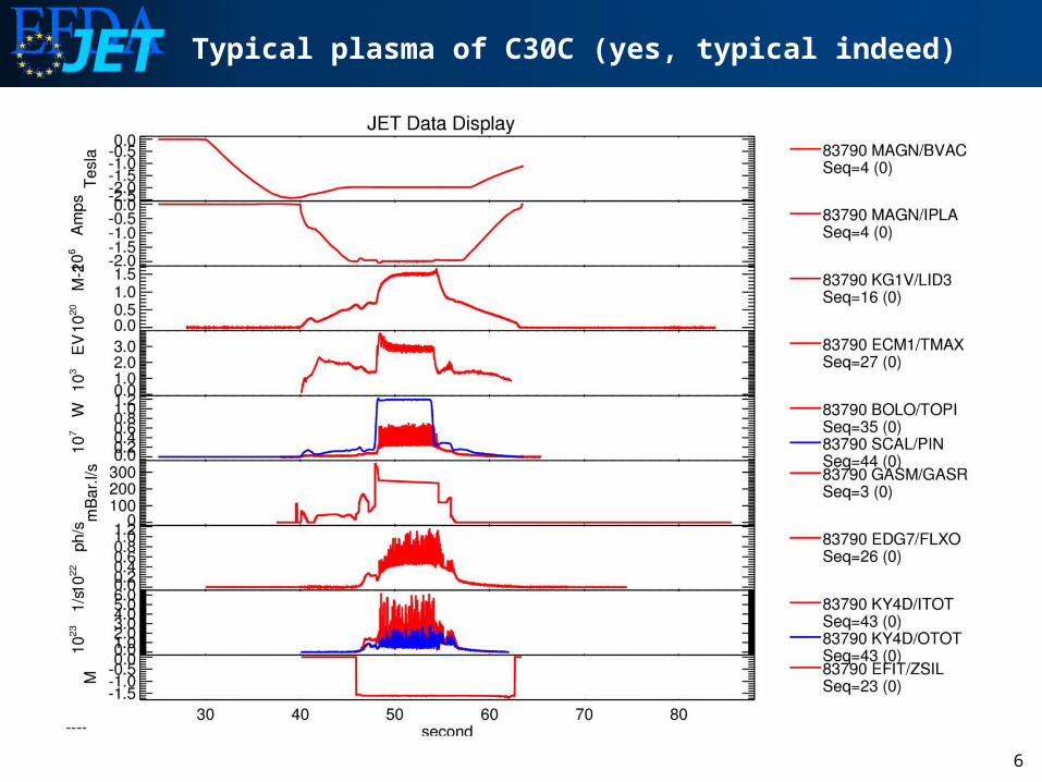
Typical plasma of C30C (yes, typical indeed)
7
Sessions summary
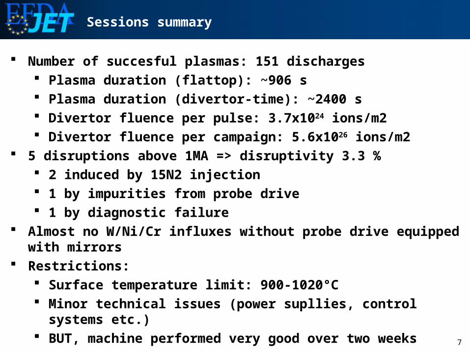
Number of succesful plasmas: 151 discharges Plasma duration (flattop): ~906 s Plasma duration (divertor-time): ~2400 s Divertor fluence per pulse: 3.7x1024 ions/m2 Divertor fluence per campaign: 5.6x1026 ions/m2
5 disruptions above 1MA => disruptivity 3.3 % 2 induced by 15N2 injection 1 by impurities from probe drive 1 by diagnostic failure
Almost no W/Ni/Cr influxes without probe drive equipped with mirrors Restrictions:
Surface temperature limit: 900-1020°C Minor technical issues (power supllies, control systems etc.) BUT, machine performed very good over two weeks

8
Gas Balances
C30C

9
Impurities
C30C C30C
Carbon Beryllium

10
Impurities
C30C
OxygenZeff
C30C
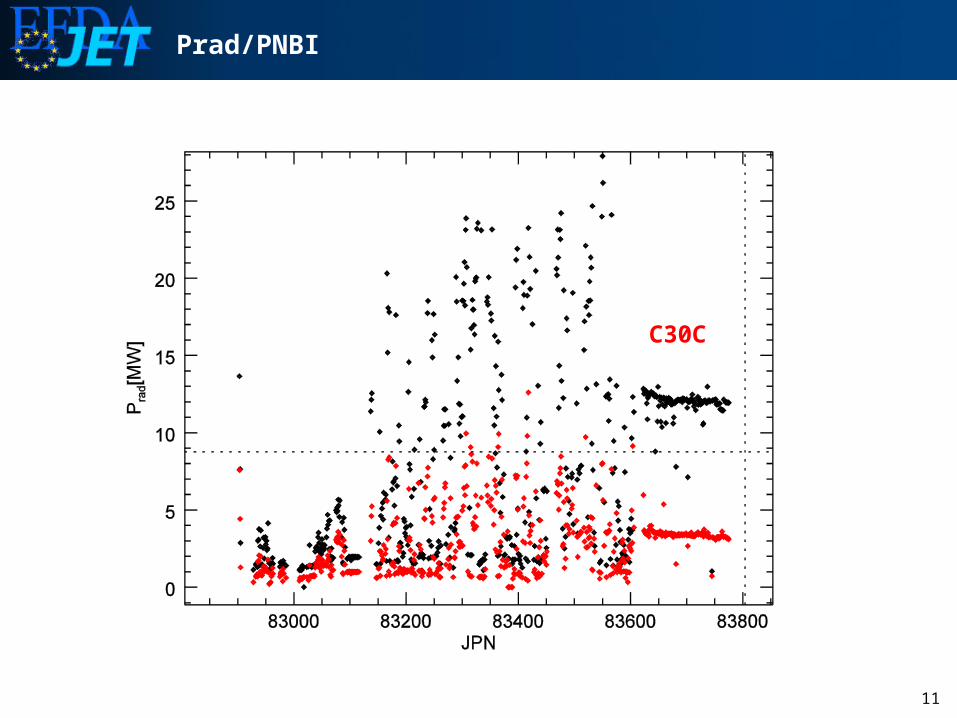
11
Prad/PNBI
C30C

12
Images
13
Experiment requirements / links to surface analysis
Ex-1.2.5 H-modes prior to long term sample retrieval with tracer injection- Main experiment to provide migration pattern specific to final H-mode phase: Mass balance will be carried out using profiling, weighing and IBA but other methods also relevant Dust collection will be used to provide dust conversion factor – link to Px-3.4.1 Dust detection after disruption
- Nitrogen 15 injected prior to repeat discharges to mark start of experiment – detection via AMS- Also to include Px-1.1.8 First mirror plasma facing tests with the reciprocating probe which will undergo
reflectivity and surface analysis of mirrors and channels after exposure
Codes: EDGE2D, OSM, ERO, WALLDYN
Ex-1.1.2 Initial first wall Be erosion, Be and W material mixing and fuel retention
All migration related surface analysis will be relevant but particular interest in analysis of indexed long term samples in the divertor which will have reached their 3000 pulse limit about now (Pulse no. ~ 83000).
Codes: EDGE2D, OSM, ERO, WALLDYN
Ex-1.1.4 Material migration to remote areas
QMB shutters will be opened during Ex-1.2.5 and shadowed area analysed also wheels from long term samples to be analysedCodes: EDGE2D, OSM, ERO
Ex-1.2.1 Be tile power handling, Bx-1.2.1 Study of accidental Be melt events, Ex-1.3.1 Disruption heat loads High resolution photo survey and removal of dump plate tiles (TC and LTS) for profiling, microscopy etc.
Codes: ENDEP, MEMOS

14
Experiment requirements / links to surface analysis
Ex-1.1.7 Divertor W erosion and ELM induced sputtering
IBA of divertor marker tiles and Mo surface marker
Codes: EDGE2D, OSM, ERO
Ex-1.1.5 Evaluation of fuel retention in all scenarios
IBA and TDS of deuterium content provides the backbone of the information
Codes: Intention is to repeat ITER analysis for JET which included some ERO based assumptions
Ex-1.1.9 Particle balance for N injection and development of removal technique
D-beam NRA needed for N14 detection, N15 detected by AMS
Ex-1.2.3 Bulk W tile power handling
Investigation (to be defined) of state of spring tension etc. in marker module removed from JET
Codes: Existing Efremov FE analysis
Ex-2.1.6 Characterisation of ICRF heating with the ILW
Analysis of tile 8 may be relevant also the proposed removal of re-ionisation, B&C and HFGC tiles for fast track
ion beam analysis. If replacement tiles are available these would be precision weighed providing a better baseline for the future.
Codes: TOPICA
Monitoring of W-coating condition and origin of W particles (UFO analysis group)
Microscopic analysis of tile surfaces and sectioning + dust collection and analysis

15
Overview of tiles to be removed in 2012
Goals Investigation of :• erosion of wall and divertor tiles• migration of impurities• deposition• fuel retention• migration of 10Be• transport of W in the divertor • T retention diagnostics (rotating collectors, mirrors, QMBs, louvre clips, deposition monitors)
Divertor tiles:• Full set of divertor tiles• 25 µm and 10µm W/Mo
IWGL, OPL, dump plate:• 7 µm Be/ 2 µm Ni• 10Be tile• Tiles for 10Be tape testing already identified
Tile 1
Tile 3
Tile 4
LBT
Tile 6Tile 7Tile 8
2XR3
2XR9
2XR10
2XR18
2XR19
2BC22BC4
4D23
4D14
4D3
Dump plates
OWPLIWGL
16
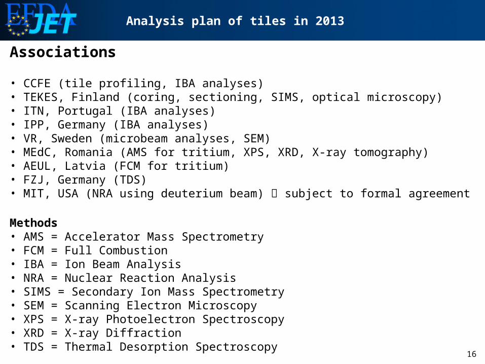
Analysis plan of tiles in 2013
Associations
• CCFE (tile profiling, IBA analyses)• TEKES, Finland (coring, sectioning, SIMS, optical microscopy)• ITN, Portugal (IBA analyses)• IPP, Germany (IBA analyses)• VR, Sweden (microbeam analyses, SEM)• MEdC, Romania (AMS for tritium, XPS, XRD, X-ray tomography)• AEUL, Latvia (FCM for tritium)• FZJ, Germany (TDS)• MIT, USA (NRA using deuterium beam) subject to formal agreement
Methods• AMS = Accelerator Mass Spectrometry• FCM = Full Combustion• IBA = Ion Beam Analysis• NRA = Nuclear Reaction Analysis• SIMS = Secondary Ion Mass Spectrometry• SEM = Scanning Electron Microscopy• XPS = X-ray Photoelectron Spectroscopy• XRD = X-ray Diffraction• TDS = Thermal Desorption Spectroscopy
17
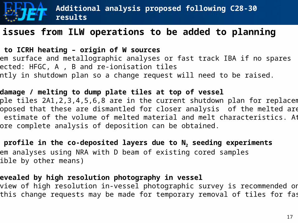
Additional analysis proposed following C28-30 results
Specific issues from ILW operations to be added to planning
Erosion due to ICRH heating – origin of W sources • Post-mortem surface and metallographic analyses or fast track IBA if no spares• Tiles affected: HFGC, A , B and re-ionisation tiles• Not currently in shutdown plan so a change request will need to be raised.
Disruption damage / melting to dump plate tiles at top of vessel• Thermocouple tiles 2A1,2,3,4,5,6,8 are in the current shutdown plan for replacement It is proposed that these are dismantled for closer analysis of the melted areas to get a better estimate of the volume of melted material and melt characteristics. At the same time a more complete analysis of deposition can be obtained.
Nitrogen 14 profile in the co-deposited layers due to N2 seeding experiments• Post-mortem analyses using NRA with D beam of existing cored samples (not possible by other means)
Anomalies revealed by high resolution photography in vessel• Prompt review of high resolution in-vessel photographic survey is recommended on the basis of this change requests may be made for temporary removal of tiles for fast track IBA
18
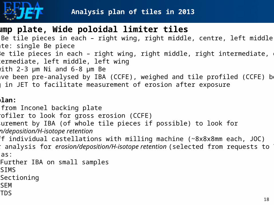
Analysis plan of tiles in 2013
IWGL, Dump plate, Wide poloidal limiter tiles • IWGL: 5 Be tile pieces in each – right wing, right middle, centre, left middle, left wing• Dump plate: single Be piece• WPL: 7 Be tile pieces in each – right wing, right middle, right intermediate, centre, • left intermediate, left middle, left wing• Coated with 2-3 µm Ni and 6-8 µm Be• Tiles have been pre-analysed by IBA (CCFE), weighed and tile profiled (CCFE) before mounting in JET to facilitate measurement of erosion after exposure
Analysis plan:1. Remove from Inconel backing plate 2. Tile profiler to look for gross erosion (CCFE)3. Re-measurement by IBA (of whole tile pieces if possible) to look for erosion/deposition/H-isotope retention 4. Part off individual castellations with milling machine (~8x8x8mm each, JOC)5. Further analysis for erosion/deposition/H-isotope retention (selected from requests to TFFT) such as:
• Further IBA on small samples• SIMS• Sectioning• SEM• TDS
19
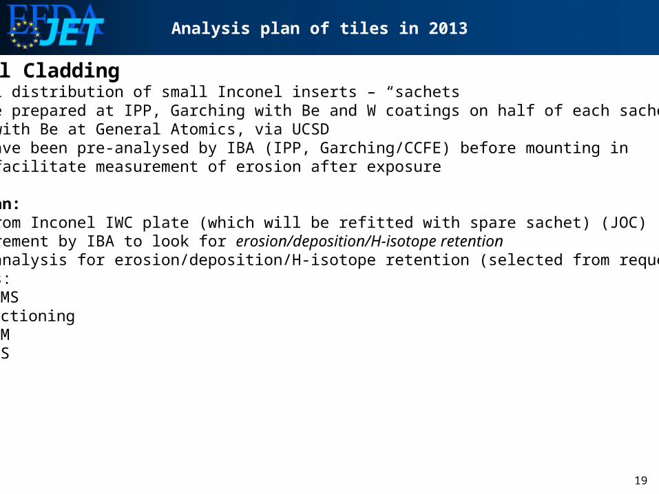
Analysis plan of tiles in 2013
Inner Wall Cladding • A toroidal distribution of small Inconel inserts – “sachets• 9 of these prepared at IPP, Garching with Be and W coatings on half of each sachet• 5 coated with Be at General Atomics, via UCSD• Samples have been pre-analysed by IBA (IPP, Garching/CCFE) before mounting in JET to facilitate measurement of erosion after exposure
Analysis plan:1. Remove from Inconel IWC plate (which will be refitted with spare sachet) (JOC)2. Re-measurement by IBA to look for erosion/deposition/H-isotope retention 3. Further analysis for erosion/deposition/H-isotope retention (selected from requests to TFFT) such as:
• SIMS• Sectioning• SEM• TDS

20
Analysis plan of tiles in 2013
Divertor tiles• Marker coated tiles 1,3,4,6,7,8 in Modules 2 and 14 • Standard divertor tiles are CFC coated with 2-3 µm Mo + 18-22 µm W (total 20-25 µm)• Marker tiles to be exchanged coated with 2-3 µm Mo + 12-14 µm W + 3-4 µm Mo + 3-4 µm W (total 20-25 µm)• Tiles have been pre-analysed by IBA (IPP, Garching) and tile profiler (CCFE) before mounting in JET to facilitate measurement of erosion after exposure
Analysis plan:1. Remove metal fastenings from tiles (JOC)2. Tile profiler to look for gross erosion (CCFE)3. Re-measurement by IBA (of whole tile pieces if possible) to look for erosion/deposition/H-isotope retention4. Cut series of 17mm diameter core samples from tile (TEKES)5. Further analysis for erosion/deposition/H-isotope retention and for interdiffusion, alloying, carbidisation etc (selected from requests to TFFT) such as:
• Further IBA on small samples• SIMS• Sectioning• SEM• TDS• XRD