EWM-COPPER EWM-SS EWM-SS-BLK SERVICE MANUALewm-copper, ewm-ss, ewm-ss-blk replacement parts wall...
13
PARTS AND SERVICE MANUAL FOR THE WALL MOUNTED FIREPLACE MODEL NUMBER: EWM-COPPER EWM-SS EWM-SS-BLK
Transcript of EWM-COPPER EWM-SS EWM-SS-BLK SERVICE MANUALewm-copper, ewm-ss, ewm-ss-blk replacement parts wall...

PARTS AND SERVICE MANUAL
FOR THE WALL MOUNTED FIREPLACE
MODEL NUMBER:
EWM-COPPER
EWM-SS EWM-SS-BLK
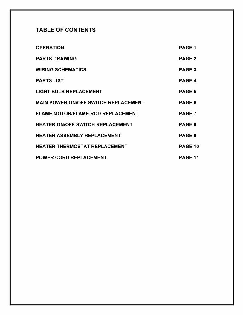
TABLE OF CONTENTS
OPERATION PAGE 1 PARTS DRAWING PAGE 2
WIRING SCHEMATICS PAGE 3
PARTS LIST PAGE 4 LIGHT BULB REPLACEMENT PAGE 5 MAIN POWER ON/OFF SWITCH REPLACEMENT PAGE 6 FLAME MOTOR/FLAME ROD REPLACEMENT PAGE 7 HEATER ON/OFF SWITCH REPLACEMENT PAGE 8 HEATER ASSEMBLY REPLACEMENT PAGE 9 HEATER THERMOSTAT REPLACEMENT PAGE 10 POWER CORD REPLACEMENT PAGE 11

1
EWM-COPPER, EWM-SS, EWM-SS-BLK OPERATION The controls are located on the lower right side of the wall mounted electric fireplace. (FIGURE 1)
A. MAIN ON/OFF SWITCH The MAIN ON/OFF SWITCH supplies power to all unit functions (heat/flame)
B. HEATER ON/OFF SWITCH The HEATER ON/OFF SWITCH supplies power to the heater fan and the heater element.
C. HEATER THERMOSTAT CONTROL To adjust the temperature to your individual requirements, turn the thermostat control clockwise all the way to turn on the heater. When the room reaches the desired temperature, turn the thermostat knob counter clockwise until you hear a click. Leave in this position to maintain the room temperature at this setting. For additional heat, turn clockwise until you hear the click again and the heater will turn on. To turn the heater off, switch the HEATER ON/OFF SWITCH to the OFF position.
NOTE: When the heater is switched ON, the heater fan will operate. The heater element may or may not be on, depending on the thermostat control setting (SEE “HEATER THERMOSTAT CONTROL”). RESETTING THE TEMPERATURE CUTOUT SWITCH The heater is protected with a safety device to prevent overheating. Should the heater overheat, an automatic cut out will turn the heater off and it will not come back on without being reset. Switching the main power switch OFF and waiting 5 minutes before switching it ON can reset the temperature cutout switch.
FIGURE 1

2
EWM-COPPER, EWM-SS, EWM-SS-BLK
10
7
8
9
6
5
4
3
2
1
10
7
8
9
6
5
4
3
2
1

3
EWM-COPPER, EWM-SS, EWM-SS-BLK WIRING DIAGRAM

4
EWM-COPPER, EWM-SS, EWM-SS-BLK REPLACEMENT PARTS
WALL MOUNT FIREPLACE
MOD LEVEL MOD A REPLACEMENT PART EWM-COPPER EWM-COPPER 1. MAIN ON/OFF SWITCH 2800070200RP 2800070200RP 2. HEATER ON/OFF SWITCH 2800070200RP 2800070200RP 3. THERMOSTAT KNOB 8800000300RP 8800000300RP 4. THERMOSTAT 2300150100RP 2300150100RP 5. HEATER ASSEMBLY 2000230100RP 2000230100RP 6. CORDSET 4100040200RP 4100040200RP 7. FLICKER MOTOR 2000140300RP 2000140300RP 8. REFLECTOR ROD 5900080600RP 5900080600RP 9. LOWER LIGHT HARNESS 2500170100RP 2500280100RP 10. GROMMET 8500260003RP 8500260003RP MOD LEVEL MOD A REPLACEMENT PART EWM-SS EWM-SS 1. MAIN ON/OFF SWITCH 2800070200RP 2800070200RP 2. HEATER ON/OFF SWITCH 2800070200RP 2800070200RP 3. THERMOSTAT KNOB 8800000300RP 8800000300RP 4. THERMOSTAT 2300150100RP 2300150100RP 5. HEATER ASSEMBLY 2000230100RP 2000230100RP 6. CORDSET 4100040200RP 4100040200RP 7. FLICKER MOTOR 2000140300RP 2000140300RP 8. REFLECTOR ROD 5900080600RP 5900080600RP 9. LOWER LIGHT HARNESS 2500170100RP 2500280100RP 10. GROMMET 8500260003RP 8500260003RP MOD LEVEL MOD A REPLACEMENT PART EWM-SS-BLK EWM-SS-BLK 1. MAIN ON/OFF SWITCH 2800070200RP 2800070200RP 2. HEATER ON/OFF SWITCH 2800070200RP 2800070200RP 3. THERMOSTAT KNOB 8800000300RP 8800000300RP 4. THERMOSTAT 2300150100RP 2300150100RP 5. HEATER ASSEMBLY 2000230100RP 2000230100RP 6. CORDSET 4100040200RP 4100040200RP 7. FLICKER MOTOR 2000140300RP 2000140300RP 8. REFLECTOR ROD 5900080600RP 5900080600RP 9. LOWER LIGHT HARNESS 2500170100RP 2500280100RP 10. GROMMET 8500260003RP 8500260003RP

5
EWM-COPPER, EWM-SS, EWM-SS-BLK LIGHT BULB REPLACEMENT Light bulbs need to be replaced when you notice a dark section in the flame or when the clarity and detail of the log exterior disappears. There are 2 light bulbs under the log set which generate the flames and embers. WARNING Allow at least 10 minutes for light bulbs to cool off before touching bulbs to avoid accidental burning of skin. LIGHT BULB REQUIREMENTS
Quantity of 2 clear chandelier or candelabra bulbs with an E-12 (small) socket base, 60 watt rating.
DO NOT EXCEED 60 WATTS PER BULB HELPFUL HINTS It is a good idea to replace all light bulbs at one time if they are close to the end of their rated life. Group replacement will reduce the number of times you need to open the unit to replace light bulbs. TOOL REQUIREMENTS Slot screwdriver LOWER BULB REPLACEMENT
1. Unplug the unit from the outlet. 2. Remove the two mounting screws from the bottom front of the heater assembly.
(FIGURE 2) 3. Loosen, but do not remove, the four heater / light assembly mounting screws located
on the bottom sides of the wall mounted electric fireplace. (FIGURE 2) 4. Slide the heater and light assembly forward to release it from the bottom of the wall
mounted electric fireplace (FIGURE 1). 5. Place heater and light assembly on a flat surface and examine the bulbs to determine
which bulb(s) require(s) replacement. 6. Unscrew the bulb(s) counter clockwise. 7. Insert new bulb(s). 8. Install the heater and light assembly onto the
four mounting screws. 9. Slide the assembly backwards to lock it into
position. 10. Tighten the four heater / light assembly mounting
screws. 11. Install the two front mounting screws. 12.Plug in the wall mounted electric fireplace.
FIGURE 1FIGURE 2

6
EWM-COPPER, EWM-SS, EWM-SS-BLK If the unit was operating prior to servicing allow at least 10 minutes for light bulbs and heating element to cool off to avoid accidental burning of skin. Disconnect power before attempting any maintenance or cleaning to reduce the risk of electric shock or damage to persons. TO REPLACE MAIN ON/OFF SWITCH
1. Unplug the unit from the outlet.
2. Remove the two mounting screws from the bottom front of the heater assembly.
3. Loosen but do not remove the four heater / light assembly mounting screws located on the bottom sides of the wall mounted electric fireplace.
4. Slide the heater and light assembly forward to release it from the bottom of the
wall mounted electric fireplace.
5. Place heater and light assembly on a flat surface and remove the six screws from the upper sides and back of the assembly.
6. Separate the flicker motor and light assembly from the lower assembly.
7. Locate the main on/off switch mounted in the lower cover and disconnect the
wiring clips and connections noting their original locations.
8. Properly orientate the new switch and connect all of the wiring clips and connections.
9. Reassemble in the reverse order as above.

7
EWM-COPPER, EWM-SS, EWM-SS-BLK If the unit was operating prior to servicing allow at least 10 minutes for light bulbs and heating element to cool off to avoid accidental burning of skin. Disconnect power before attempting any maintenance or cleaning to reduce the risk of electric shock or damage to persons. TO REPLACE FLAME MOTOR/FLAME ROD
1. Unplug the unit from the outlet.
2. Remove the two mounting screws from the bottom front of the heater assembly.
3. Loosen but do not remove the four heater / light assembly mounting screws located on the bottom sides of the wall mounted electric fireplace.
4. Slide the heater and light assembly forward to release it from the bottom of the
wall mounted electric fireplace.
5. Place heater and light assembly on a flat surface and remove the six screws from the upper sides and back of the assembly.
6. Separate the flicker motor and light assembly from the lower assembly.
7. Locate and disconnect the wiring connections for the flame motor noting their
original locations.
8. Remove the flame motor mounting bracket screws and pull the assembly out of the mounting bracket.
NOTE: When removing the flame motor some damage may occur to the flame rod. If flame rod is damaged replace to insure proper operation.
9. To remove the flame rod attach needle nose pliers to the spring on the motor
shaft and pull while rotating in the same direction of the spring winding.
10. To replace the flame rod attach needle nose pliers to the flame rod spring and push onto the flame motor shaft while rotating in the same direction of the spring winding.
11. Properly orientate the flame motor and connect all of the wiring clips connections
in their original locations.
12. Reassemble in the reverse order as above.

8
EWM-COPPER, EWM-SS, EWM-SS-BLK If the unit was operating prior to servicing allow at least 10 minutes for light bulbs and heating element to cool off to avoid accidental burning of skin. Disconnect power before attempting any maintenance or cleaning to reduce the risk of electric shock or damage to persons. TO REPLACE HEATER ON/OFF SWITCH
1. Unplug the unit from the outlet.
2. Remove the two mounting screws from the bottom front of the heater assembly.
3. Loosen but do not remove the four heater / light assembly mounting screws located on the bottom sides of the wall mounted electric fireplace.
4. Slide the heater and light assembly forward to release it from the bottom of the
wall mounted electric fireplace.
5. Place heater and light assembly on a flat surface and remove the six screws from the upper sides and back of the assembly.
6. Separate the flicker motor and light assembly from the lower assembly.
7. Locate the heater on/off switch mounted in the lower cover and disconnect the
wiring clips and connections noting their original locations.
8. Properly orientate the new switch and connect all of the wiring clips and connections.
9. Reassemble in the reverse order as above.

9
EWM-COPPER, EWM-SS, EWM-SS-BLK If the unit was operating prior to servicing allow at least 10 minutes for light bulbs and heating element to cool off to avoid accidental burning of skin. Disconnect power before attempting any maintenance or cleaning to reduce the risk of electric shock or damage to persons. TO REPLACE HEATER ASSEMBLY
1. Unplug the unit from the outlet.
2. Remove the two mounting screws from the bottom front of the heater assembly.
3. Loosen but do not remove the four heater / light assembly mounting screws located on the bottom sides of the wall mounted electric fireplace.
4. Slide the heater and light assembly forward to release it from the bottom of the
wall mounted electric fireplace.
5. Place heater and light assembly on a flat surface and remove the six screws from the upper sides and back of the assembly.
6. Turn the heater and light assembly over and remove the four heater mounting
screws.
7. Separate the flicker motor and light assembly from the lower assembly.
8. Locate the heater assembly and disconnect the wiring clips and connections noting their original locations.
9. Properly orientate the heater assembly and connect all of the wiring clips and
connections.
10. Reassemble in the reverse order as above.

10
EWM-COPPER, EWM-SS, EWM-SS-BLK If the unit was operating prior to servicing allow at least 10 minutes for light bulbs and heating element to cool off to avoid accidental burning of skin. Disconnect power before attempting any maintenance or cleaning to reduce the risk of electric shock or damage to persons. TO REPLACE HEATER THERMOSTAT CONTROL
1. Unplug the unit from the outlet.
2. Remove the two mounting screws from the bottom front of the heater assembly.
3. Loosen but do not remove the four heater / light assembly mounting screws located on the bottom sides of the wall mounted electric fireplace.
4. Slide the heater and light assembly forward to release it from the bottom of the
wall mounted electric fireplace.
5. Place heater and light assembly on a flat surface and remove the six screws from the upper sides and back of the assembly.
6. Separate the flicker motor and light assembly from the lower assembly.
7. Locate the heater thermostat mounted in the lower cover and disconnect the
wiring clips and connections noting their original locations.
8. Remove the thermostat control knob to expose the mounting screws.
9. Remove the mounting screws and remove the heater thermostat control switch.
9. Properly orientate the new thermostat and connect all of the wiring clips and connections.
10. Reassemble in the reverse order as above.

11
EWM-COPPER, EWM-SS, EWM-SS-BLK If the unit was operating prior to servicing allow at least 10 minutes for light bulbs and heating element to cool off to avoid accidental burning of skin. Disconnect power before attempting any maintenance or cleaning to reduce the risk of electric shock or damage to persons. TO REPLACE THE POWER CORD
1. Unplug the unit from the outlet.
2. Remove the two mounting screws from the bottom front of the heater assembly.
3. Loosen but do not remove the four heater / light assembly mounting screws located on the bottom sides of the wall mounted electric fireplace.
4. Slide the heater and light assembly forward to release it from the bottom of the
wall mounted electric fireplace.
5. Place heater and light assembly on a flat surface and remove the six screws from the upper sides and back of the assembly.
6. Separate the flicker motor and light assembly from the lower assembly.
7. Locate and disconnect the power cord wiring connections noting their original
locations.
8. With needle nose pliers grasp the power cord strain relief grommet from inside the lower cover and push while twisting to remove.
9. Pull the power cord out through the hole in the lower cover.
10. Install the new power cord through the hole in the lower cover and connect all of
the wiring connections in their original locations.
11. Install the power cord retaining grommet on the power cord and insert into the hole in the lower cover.
12. Reassemble in the reverse order as above.