EVPF/NC - DN 200 ÷ 300 1 2 -...
9
1 EVP... DN 200÷300 CHAPTER 2.2 SECTION 1 EVPF/NC - DN 200 ÷ 300 EVPF... II 3G - II 3D MADAS-01 ELETTROVALVOLE NORMALMENTE CHIUSE AUTOMATICHE TIPO EVPF.../NC DN 200÷300 EVPF.../NC DN 200÷300 AUTOMATIC NORMALLY CLOSED SOLENOID VALVES P. max 360 mbar Madas Technical Manual REV. 1 of 1s t March 2016 DESCRIZIONE Elettrovalvole automatiche normalmente chiuse di intercettazione per gas che aprono quando sono alimentate elettricamente e chiudono quando viene tolta tensione. Regolatore di portata incorporato. L’elettrovalvola può essere fornita anche con il microswitch di segnalazione (CPI Switch) e con possibilità di regolazione velocità apertura (versioni EVPR). Norma di riferimento EN 161 In conformità a: Direttiva ATEX 2014/34/UE (ex 94/9/CE) Direttiva EMC 2014/30/UE (ex 2004/108/CE) Direttiva LVD 2014/35/UE (ex 2006/95/CE) DESCRIPTION Gas interception automatic normally closed solenoid valves that open when they are powered and close when there is no tension. Equipped flow regulator . The solenoid valve can be supplied also with the closed position indicator switch (CPI Switch) and with the possibility of speed opening adjustment (EVPR versions). Reference standard EN 161 In conformity with: 2014/34/EU ATEX Directive (ex 94/9/EC) 2014/30/EU EMC Directive (ex 2004/108/EC) 2014/35/EU LVD Directive (ex 2006/95/EC)
-
Upload
trinhnguyet -
Category
Documents
-
view
214 -
download
0
Transcript of EVPF/NC - DN 200 ÷ 300 1 2 -...
1EVP...DN 200÷300
Chapter
2.2SeCtion
1EVPF/NC - DN 200 ÷ 300
EVPF...II 3G - II 3D
MADAS-01
ELETTROVALVOLE NORMALMENTE CHIUSE AUTOMATICHE TIPO EVPF.../NC DN 200÷300EVPF.../NC DN 200÷300 AUTOMATIC NORMALLY CLOSED SOLENOID VALVES
P. max 360 mbar
Madas Technical ManualREV. 1 of 1st March 2016
DESCRIZIONE
Elettrovalvole automatiche normalmente chiuse di intercettazione per gas che aprono quando sono alimentate elettricamente e chiudono quando viene tolta tensione.
Regolatore di portata incorporato.
L’elettrovalvola può essere fornita anche con il microswitch di segnalazione (CPI Switch) e con possibilità di regolazione velocità apertura (versioni EVPR).
Norma di riferimento EN 161
In conformità a:
Direttiva ATEX 2014/34/UE(ex 94/9/CE)
Direttiva EMC 2014/30/UE(ex 2004/108/CE)
Direttiva LVD 2014/35/UE(ex 2006/95/CE)
DESCRIPTION
Gas interception automatic normally closed solenoid valves that open when they are powered and close when there is no tension.
Equipped flow regulator.
The solenoid valve can be supplied also with the closed position indicator switch (CPI Switch) and with the possibility of speed opening adjustment (EVPR versions).
Reference standard EN 161
In conformity with:
2014/34/EU ATEX Directive(ex 94/9/EC)
2014/30/EU EMC Directive(ex 2004/108/EC)
2014/35/EU LVD Directive(ex 2006/95/EC)

2 EVP...DN 200÷300
Chapter
2.2SeCtion
1 EVPF/NC - DN 200 ÷ 300P. max 360 mbar
Madas Technical ManualREV. 1 of 1st March 2016
fig. 1 - carter (6) aperto
Per regolare la portata bisogna svitare la vite (17) e spostare il carter (6) verso l'alto come in figura sotto
fig. 1 - sump (6) open
To adjust the flow rate loose the screw (17) and shift up the sump (6) as per as shown below.
3EVP...DN 200÷300
Chapter
2.2SeCtion
1EVPF/NC - DN 200 ÷ 300P. max 360 mbar
Madas Technical ManualREV. 1 of 1st March 2016
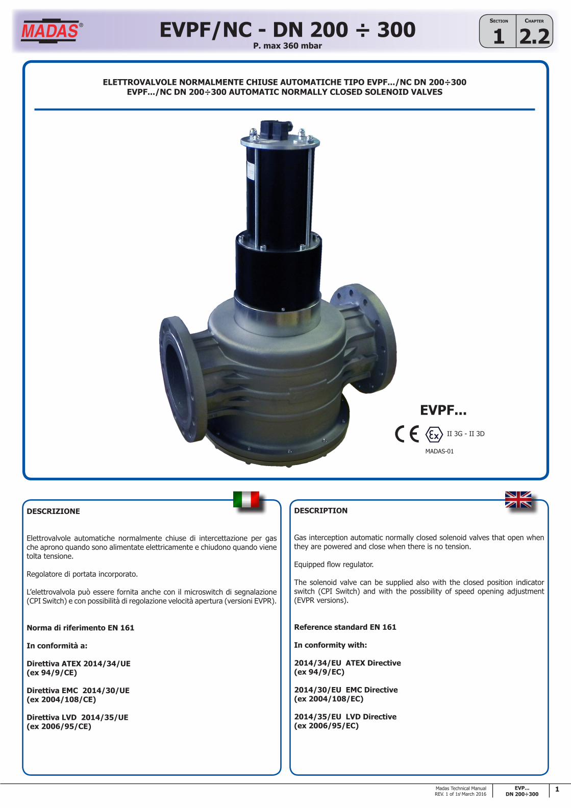
fig. 1 e 2
1. Dadi di fissaggio coperchio superiore2. Regolazione velocità apertura (solo versioni lente)3. Tappo di accesso regolazione4. Pompa attuatore5. Viti di fissaggio KIT ATTUATORE6. Carter di protezione regolazioni7. Vite fissaggio regolazione CPI Switch (optional)8. Closed Position Indicator Switch (optional)9. Perno superiore10. Perno centrale11. Fondello12. Viti fissaggio fondello13. Molla di chiusura14. Otturatore15. O-Ring tenuta fondello16. Corpo valvola17. Vite fissaggio carter18. Vite fissaggio Switch regolazione portata19. Switch regolazione portata20. Dischetto per contatti su micro21. Valvola N.A. automatica (circuito olio)22. Connettore valvola (circuito olio)23. Bobina valvola (circuito olio)24. Gruppo attuatore25. Cilindro idraulico26. Coperchio superiore27. Tappo serbatoio olio28. Serbatoio olio29. Connettore collegamento CPI Switch30. Connettore alimentazione elettrovalvola
vista dall'alto del coperchio (26) view from above without cover (26)
fig. 2
carter (6) chiusosump (6) closed
fig. 1 and 2
1. Fixing nuts for the top cover2. Adjustment of the opening speed(only for slow opening version)3. Cap for access to the adjustment 4. Pump (actuator)5. Fixing screws for ACTUATOR KIT6. Sump to protect the settings7. Fixing screw for CPI Switch adjustment8. Closed Position Indicator Switch (optional)9. Upper pin10. Central pin11. Bottom12. Fixing screws for bottom13. Closing spring14. Obturator15. Bottom seal O-Ring16. Valve body17. Fixing screw for sump18. Fixing screw for flow adjustment switch19. Flow adjustment switch20. Disk cfor microswitch contacts21. N.O. automatic valve (oil circuit)22. Valve connector (oil circuit)23. Valve coil (oil circuit)24. Actuator assembly25. Hydraulic cylinder26. Upper cover27. Oil filler cap28. Oil tank29. CPI Switch connection connector30. Solenod valve power connector

4 EVP...DN 200÷300
Chapter
2.2SeCtion
1 EVPF/NC - DN 200 ÷ 300P. max 360 mbar
Madas Technical ManualREV. 1 of 1st March 2016
CARATTERISTICHE TECNICHE
• Impiego: gas non aggressivi delle 3 famiglie (gas secchi). Su richiesta versioni idonee per biogas (solo corpi in alluminio)
• Attacchi flangiati PN 16: DN 200 ÷ DN 300 secondo ISO 7005
• Su richiesta attacchi flangiati ANSI 150
• Tensione di alimentazione: 24 Vdc, 24 V/50 Hz, 110 V/50 Hz, 230 V/50-60 Hz
• Tolleranza su tensione di alimentazione: -15% ... +10%
• Potenza max assorbita (fase di apertura / regime): 47 / 5 VA
• Pressione max esercizio: 360 mbar
• Temperatura ambiente: -20 ÷ +60 °C
• Grado di protezione: IP65
• Classe A (DN 200) - Classe B (DN 250 - DN 300)
• Gruppo: 2
• Tempo di apertura totale otturatore (ta= 25 °C Vn=230 V): DN 200: 13 s ± 20% - DN 250: 16 s ± 20% - DN 300: 18 s ± 20%
• Range tempo apertura (su versioni lente): fino a 40 s ± 20% (ta= 25 °C Vn=230 V)
MATERIALI
• Alluminio fuso (UNI EN 1706)
• Ottone OT-58 (UNI EN 12164)
• Alluminio 11S (UNI 9002-5)
• Acciaio zincato e acciaio INOX 430 F (UNI EN 10088)
• Gomma antiolio NBR e Viton (UNI 7702)
PESI
DN 200
• Netto: circa 101 Kg
• Lordo: circa 141 Kg
DN 250
• Netto: circa 140 Kg
• Lordo: circa 170 Kg
DN 300
• Netto: circa 160 Kg
• Lordo: circa 200 Kg
TECHNICAL DATA
• Use: not aggressive gases of the 3 families (dry gases) On request biogas versions available too (only on aluminum bodies)
• Flanged connections PN 16: DN 200 ÷ DN 300 according to ISO 7005
• ANSI 150 flanged connections on request
• Power supply voltage: 24 Vdc, 24 V/50 Hz, 110 V/50 Hz, 230 V/50-60 Hz
• Power supply voltage tolerance: -15% ... +10%
• Max. Power absorption: (opening phase / regime): 47 / 5 VA
• Max. working pressure: 360 mbar
• Environment temperature: -20 ÷ +60 °C
• Protection degree: IP65
• Class A (DN 200) - Class B (DN 250 - DN 300)
• Group: 2
• Total openig time of the obturator (ta= 25 °C Vn=230 V): DN 200: 13 s ± 20% - DN 250: 16 s ± 20% - DN 300: 18 s ± 20%
• Openig time range (on slow opening versions): until 40 s ± 20% (ta= 25 °C Vn=230 V)
MATERIALS
• Aluminium (UNI EN 1706)
• OT-58 brass (UNI EN 12164)
• 11S aluminium (UNI 9002-5)
• Galvanized and 430 F stainless steel (UNI EN 10088)
• NBR and Viton rubber (UNI 7702)
WEIGHT
DN 200
• Net: about 101 Kg
• Gross: about 141 Kg
DN 250
• Net: about 140 Kg
• Gross: about 170 Kg
DN 300
• Net: about 160 Kg
• Gross: about 200 Kg
5EVP...DN 200÷300
Chapter
2.2SeCtion
1EVPF/NC - DN 200 ÷ 300P. max 360 mbar
Madas Technical ManualREV. 1 of 1st March 2016
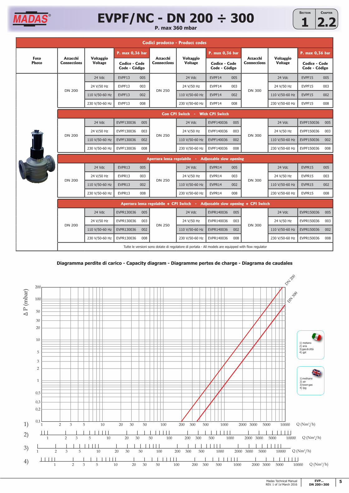
1) metano2) aria3) gas di città4) gpl
1) methane2) air3) town gas4) lpg
Diagramma perdite di carico - Capacity diagram - Diagramme pertes de charge - Diagrama de caudales
Codici prodotto - Product codes
FotoPhoto
AttacchiConnections
VoltaggioVoltage
P. max 0,36 barAttacchi
ConnectionsVoltaggioVoltage
P. max 0,36 barAttacchi
ConnectionsVoltaggioVoltage
P. max 0,36 bar
Codice - CodeCode - Código
Codice - CodeCode - Código
Codice - CodeCode - Código
DN 200
24 Vdc EVPF13 005
DN 250
24 Vdc EVPF14 005
DN 300
24 Vdc EVPF15 005
24 V/50 Hz EVPF13 003 24 V/50 Hz EVPF14 003 24 V/50 Hz EVPF15 003
110 V/50-60 Hz EVPF13 002 110 V/50-60 Hz EVPF14 002 110 V/50-60 Hz EVPF15 002
230 V/50-60 Hz EVPF13 008 230 V/50-60 Hz EVPF14 008 230 V/50-60 Hz EVPF15 008
Con CPI Switch - With CPI Switch
DN 200
24 Vdc EVPF130036 005
DN 250
24 Vdc EVPF140036 005
DN 300
24 Vdc EVPF150036 005
24 V/50 Hz EVPF130036 003 24 V/50 Hz EVPF140036 003 24 V/50 Hz EVPF150036 003
110 V/50-60 Hz EVPF130036 002 110 V/50-60 Hz EVPF140036 002 110 V/50-60 Hz EVPF150036 002
230 V/50-60 Hz EVPF130036 008 230 V/50-60 Hz EVPF140036 008 230 V/50-60 Hz EVPF150036 008
Apertura lenta regolabile - Adjustable slow opening
DN 200
24 Vdc EVPR13 005
DN 250
24 Vdc EVPR14 005
DN 300
24 Vdc EVPR15 005
24 V/50 Hz EVPR13 003 24 V/50 Hz EVPR14 003 24 V/50 Hz EVPR15 003
110 V/50-60 Hz EVPR13 002 110 V/50-60 Hz EVPR14 002 110 V/50-60 Hz EVPR15 002
230 V/50-60 Hz EVPR13 008 230 V/50-60 Hz EVPR14 008 230 V/50-60 Hz EVPR15 008
Apertura lenta regolabile + CPI Switch - Adjustable slow opening + CPI Switch
DN 200
24 Vdc EVPR130036 005
DN 250
24 Vdc EVPR140036 005
DN 300
24 Vdc EVPR150036 005
24 V/50 Hz EVPR130036 003 24 V/50 Hz EVPR140036 003 24 V/50 Hz EVPR150036 003
110 V/50-60 Hz EVPR130036 002 110 V/50-60 Hz EVPR140036 002 110 V/50-60 Hz EVPR150036 002
230 V/50-60 Hz EVPR130036 008 230 V/50-60 Hz EVPR140036 008 230 V/50-60 Hz EVPR150036 008
Tutte le versioni sono dotate di regolatore di portata - All models are equipped with flow regulator
DN 300
6 EVP...DN 200÷300
Chapter
2.2SeCtion
1 EVPF/NC - DN 200 ÷ 300P. max 360 mbar
Madas Technical ManualREV. 1 of 1st March 2016
INSTALLAZIONE
L’elettrovalvola è conforme alla Direttiva 2014/34/UE (ex 94/9/CE) come apparecchio del gruppo II, categoria 3G e come apparecchio del gruppo II, categoria 3D; come tale è idonea per essere installata nelle zone 2 e 22 come classificate nell’allegato I alla Direttiva 99/92/CE.
L’elettrovalvola non è idonea per l’utilizzo nelle zone 1 e 21 e, a maggior ragione, nelle zone 0 e 20 come definite nella già citata Direttiva 99/92/CE.
Per determinare la qualifica e l’estensione delle zone pericolose si veda la norma CEI EN 60079-10-1. L’apparecchio, se installato e sottoposto a manutenzione nel pieno rispetto di tutte le condizioni e istruzioni tecniche riportate nel presente documento, non costituisce fonte di pericoli specifici: in particolare, in condizioni di normale funzionamento, non è prevista, da parte dell’elettrovalvola, l’emissione in atmosfera di sostanza infiammabile con modalità tali da originare un’atmosfera esplosiva.
ATTENZIONE: le operazioni di installazione/cablaggio/manutenzione devono essere eseguite da personale qualificato.
• E’ necessario chiudere il gas prima dell’installazione.
• Verificare che la pressione di linea NON SIA SUPERIORE alla pressione massima dichiarata sull’etichetta del prodotto.
• Devono essere installate con la freccia (indicata sul corpo dell’apparecchio) rivolta verso l’utenza, con la tubazione in orizzontale e attuatore rivolto verso l'alto (come in fig. 1 e 2).
• Durante l’installazione evitare che detriti o residui metallici penetrino all’interno dell’apparecchio.
• Verificare che le controflange di ingresso e uscita siano perfettamente parallele per evitare di sottoporre il corpo a inutili sforzi meccanici, calcolare inoltre lo spazio per l’inserimento della guarnizione di tenuta. Se a guarnizioni inserite lo spazio rimanente è eccessivo non cercare di colmarlo stringendo eccessivamente i bulloni dell’apparecchio.
• In ogni caso dopo l’installazione verificare la tenuta dell’impianto.
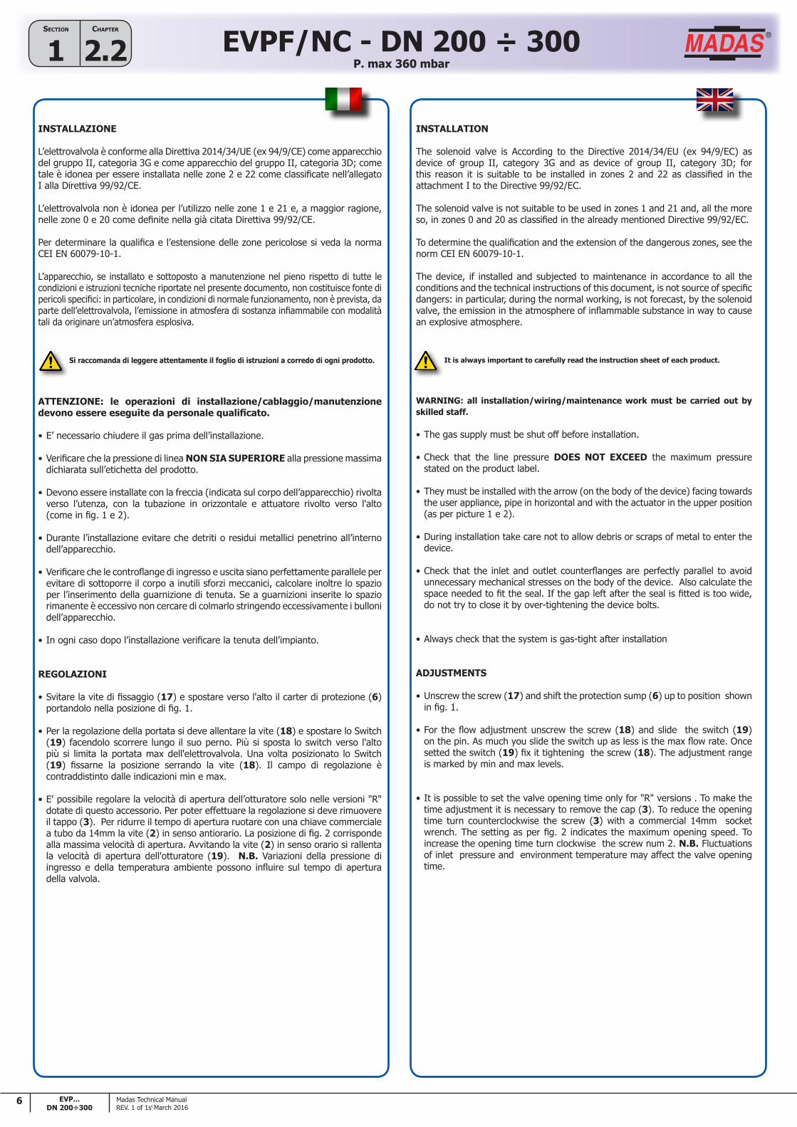
REGOLAZIONI
• Svitare la vite di fissaggio (17) e spostare verso l'alto il carter di protezione (6) portandolo nella posizione di fig. 1.
• Per la regolazione della portata si deve allentare la vite (18) e spostare lo Switch (19) facendolo scorrere lungo il suo perno. Più si sposta lo switch verso l'alto più si limita la portata max dell'elettrovalvola. Una volta posizionato lo Switch (19) fissarne la posizione serrando la vite (18). Il campo di regolazione è contraddistinto dalle indicazioni min e max.
• E' possibile regolare la velocità di apertura dell’otturatore solo nelle versioni "R" dotate di questo accessorio. Per poter effettuare la regolazione si deve rimuovere il tappo (3). Per ridurre il tempo di apertura ruotare con una chiave commerciale a tubo da 14mm la vite (2) in senso antiorario. La posizione di fig. 2 corrisponde alla massima velocità di apertura. Avvitando la vite (2) in senso orario si rallenta la velocità di apertura dell'otturatore (19). N.B. Variazioni della pressione di ingresso e della temperatura ambiente possono influire sul tempo di apertura della valvola.
Si raccomanda di leggere attentamente il foglio di istruzioni a corredo di ogni prodotto.
INSTALLATION
The solenoid valve is According to the Directive 2014/34/EU (ex 94/9/EC) as device of group II, category 3G and as device of group II, category 3D; for this reason it is suitable to be installed in zones 2 and 22 as classified in the attachment I to the Directive 99/92/EC.
The solenoid valve is not suitable to be used in zones 1 and 21 and, all the more so, in zones 0 and 20 as classified in the already mentioned Directive 99/92/EC.
To determine the qualification and the extension of the dangerous zones, see the norm CEI EN 60079-10-1.
The device, if installed and subjected to maintenance in accordance to all the conditions and the technical instructions of this document, is not source of specific dangers: in particular, during the normal working, is not forecast, by the solenoid valve, the emission in the atmosphere of inflammable substance in way to cause an explosive atmosphere.
WARNING: all installation/wiring/maintenance work must be carried out by skilled staff.
• The gas supply must be shut off before installation.
• Check that the line pressure DOES NOT EXCEED the maximum pressure stated on the product label.
• They must be installed with the arrow (on the body of the device) facing towards the user appliance, pipe in horizontal and with the actuator in the upper position (as per picture 1 e 2).
• During installation take care not to allow debris or scraps of metal to enter the device.
• Check that the inlet and outlet counterflanges are perfectly parallel to avoid unnecessary mechanical stresses on the body of the device. Also calculate the space needed to fit the seal. If the gap left after the seal is fitted is too wide, do not try to close it by over-tightening the device bolts.
• Always check that the system is gas-tight after installation
ADJUSTMENTS
• Unscrew the screw (17) and shift the protection sump (6) up to position shown in fig. 1.
• For the flow adjustment unscrew the screw (18) and slide the switch (19) on the pin. As much you slide the switch up as less is the max flow rate. Once setted the switch (19) fix it tightening the screw (18). The adjustment range is marked by min and max levels.
• It is possible to set the valve opening time only for "R" versions . To make the time adjustment it is necessary to remove the cap (3). To reduce the opening time turn counterclockwise the screw (3) with a commercial 14mm socket wrench. The setting as per fig. 2 indicates the maximum opening speed. To increase the opening time turn clockwise the screw num 2. N.B. Fluctuations of inlet pressure and environment temperature may affect the valve opening time.
It is always important to carefully read the instruction sheet of each product.
7EVP...DN 200÷300
Chapter
2.2SeCtion
1EVPF/NC - DN 200 ÷ 300P. max 360 mbar
Madas Technical ManualREV. 1 of 1st March 2016
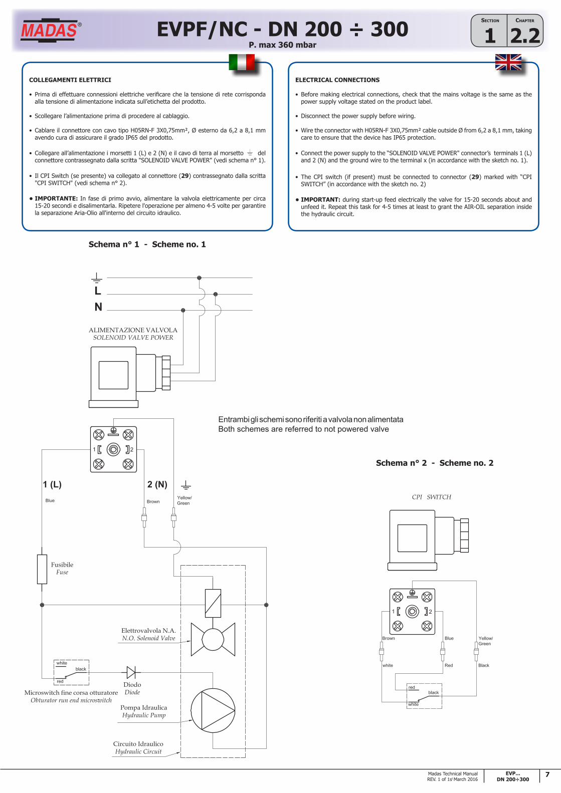
Schema n° 1 - Scheme no. 1
Schema n° 2 - Scheme no. 2
Entrambi gli schemi sono riferiti a valvola non alimentataBoth schemes are referred to not powered valve
COLLEGAMENTI ELETTRICI
• Prima di effettuare connessioni elettriche verificare che la tensione di rete corrisponda alla tensione di alimentazione indicata sull’etichetta del prodotto.
• Scollegare l’alimentazione prima di procedere al cablaggio.
• Cablare il connettore con cavo tipo H05RN-F 3X0,75mm², Ø esterno da 6,2 a 8,1 mm avendo cura di assicurare il grado IP65 del prodotto.
• Collegare all’alimentazione i morsetti 1 (L) e 2 (N) e il cavo di terra al morsetto del connettore contrassegnato dalla scritta "SOLENOID VALVE POWER" (vedi schema n° 1).
• Il CPI Switch (se presente) va collegato al connettore (29) contrassegnato dalla scritta "CPI SWITCH" (vedi schema n° 2).
• IMPORTANTE: In fase di primo avvio, alimentare la valvola elettricamente per circa 15-20 secondi e disalimentarla. Ripetere l'operazione per almeno 4-5 volte per garantire la separazione Aria-Olio all'interno del circuito idraulico.
ELECTRICAL CONNECTIONS
• Before making electrical connections, check that the mains voltage is the same as the power supply voltage stated on the product label.
• Disconnect the power supply before wiring.
• Wire the connector with H05RN-F 3X0,75mm² cable outside Ø from 6,2 a 8,1 mm, taking care to ensure that the device has IP65 protection.
• Connect the power supply to the “SOLENOID VALVE POWER" connector’s terminals 1 (L) and 2 (N) and the ground wire to the terminal x (in accordance with the sketch no. 1).
• The CPI switch (if present) must be connected to connector (29) marked with “CPI SWITCH” (in accordance with the sketch no. 2)
• IMPORTANT: during start-up feed electrically the valve for 15-20 seconds about and unfeed it. Repeat this task for 4-5 times at least to grant the AIR-OIL separation inside the hydraulic circuit.

8 EVP...DN 200÷300
Chapter
2.2SeCtion
1 EVPF/NC - DN 200 ÷ 300P. max 360 mbar
Madas Technical ManualREV. 1 of 1st March 2016
MANUTENZIONE
In ogni caso prima di effettuare operazioni di manutenzione sull'aparecchio è necessario accertarsi che:
1. l’apparecchio non sia alimentato elettricamente (scollegare i connettori elettrici posizionati sopra il coperchio (26))
2. all'interno dell’apparecchio non vi sia gas in pressione
Sostituzione gruppo attuatore (24)
Operare come indicato di seguito:
• Svitare la vite di fissaggio (17) e spostare verso l'alto il carter di protezione (6) portandolo nella posizione di fig. 3.
• Allentare le viti di fissaggio (7) e (18). Ruotare entrambi i microswitch (8) e (19) di 180° come raffigurato in fig. 3 e fissarli momentaneamente in questa posizione.
• Svitare e rimuovere le viti di fissaggio (5).
• Ora è possibile rimuovere (sfilandolo verso l'alto) il kit attuatore (24)
• Posizionare il nuovo kit attuatore (24) precedente nella stessa posizione del precedente e fissarlo serrando le viti (5).
• Riposizionare i microswitch (8) e (19) nelle posizione originali (come in fig. 1).
• Posizionare il CPI Switch (8), ruotandoli, in modo che a valvola chiusa il disco (20) chiuda il contatto (vedi fig. 1).
• Per il switch di regolazione portata (19) seguire le indicazioni riportate nel paragrafo "REGOLAZIONI".
• Abbassare il carter di protezione (6) e fissarlo tramite la vite (5).
• Cablare elettricamente il nuovo gruppo attuatore seguendo le istruzioni riportate al paragrafo "COLLEGAMENTI ELETTRICI".
• Alimentare e disalimentare l'elettrovalvola 2 o 3 volte verificandone la completa apertura e chiusura, testando così il corretto funzionamento dopo le operazioni di manutenzione.
ATTENZIONE: le operazioni di installazione/cablaggio/manutenzione devono essere eseguite da personale qualificato.
SERVICING
In all cases, before performing any internal checks make sure that:
1. the valve must not be powered (disconnect the electrical connectors placed on the top of the cover (26))
2. there is no pressurised gas inside the device
Actuator assembly replacement (24)
Do as follows:
• Unscrew the fixing screw (17) and shift the protection sump (6) up to position shown in fig. 3.
• Loose the fixing screws (7) and (18). Rotate 180 degrees both the microswitches (8) and (19) as per fig. 3 and temporary fix them in this position.
• Unscrew and remove the fixing screws (5).
• Now you can remove (from the top) the acturator kit (24)
• Place the new acturator kit (24) in the same location as the previous and fix it tightening the screws (5).
• Place the microswitches (8) and (19) to the original position (as per fig. 1)
• Rotate the CPI Switch (8) so that, when the valve is closed, the disk closes the contact (see fig. 1).
• Concerning the flow adjustment switch (19) follow the instructions on chapter “REGULATIONS”.
• Shift down the protection casing (6) and fix it with the screw (5).
• Electrically wire the new actuator assembly following the instructions on chapter “ELECTRICAL CONNECTIONS”.
• Power and power down the valve 2, 3 times verifying the complete valve opening and closing, thus testing the correct working after the maintenance operations.
WARNING: all installation/wiring/maintenance work must be carried out by skilled staff.
fig. 3
Gruppo attuatore (24) installato sulla valvola con carter (6) apertoActuator assembly (24) with open sump (6) mounted on the valve
Gruppo attuatore (24) separato dalla valvola con carter (6) chiuso
Actuator assembly (24) with closed sump (6) unmounted on the valve

9EVP...DN 200÷300
Chapter
2.2SeCtion
1EVPF/NC - DN 200 ÷ 300P. max 360 mbar
Madas Technical ManualREV. 1 of 1st March 2016
Dimensioni di ingombro in mm - Overall dimensions in mm
Attacchi flangiati Flanged connections A B C
DN 200 600 920 450
DN 250 673 1020 510
DN 300 737 1160 552


![Angle Seat Globe Valve, Metal · 550 3 Kv values [m³/h] DN 6 DN 8 DN 10 DN 15 DN 20 DN 25 DN 32 DN 40 DN 50 DN 65 DN 80 Butt weld spigots, DIN 11850 1.6 1.8 2.4 2.4 - - - - - - -](https://static.fdocuments.us/doc/165x107/5f9509c77c6fed50eb12dcff/angle-seat-globe-valve-metal-550-3-kv-values-mh-dn-6-dn-8-dn-10-dn-15-dn-20.jpg)