EVALUATION OF THE INFLUENCE OF ICING ON WINGS ON … · 3 The aircraft icing definition: The...
14
EVALUATION OF THE INFLUENCE OF ICING ON WINGS ON AIRCRAFT FLIGHT PARAMETERS Poznan University of Technology Institute of Combustion Engines and Transport Faculty of Transport Engineering Damian Olejniczak, Marcin Nowacki E-mail address: [email protected]
Transcript of EVALUATION OF THE INFLUENCE OF ICING ON WINGS ON … · 3 The aircraft icing definition: The...

EVALUATION OF THE INFLUENCE OF ICING ON
WINGS ON AIRCRAFT FLIGHT PARAMETERS
Poznan University of Technology
Institute of Combustion Engines and Transport
Faculty of Transport Engineering
Damian Olejniczak, Marcin Nowacki
E-mail address: [email protected]

2 Presentation plan:
Introduction
the aircraft icing definition
conditions conductive to icing of the aircraft structure
the shape and structure of icing on the surface of the aircraft wing
the effect of icing on the aircraft's flight characteristics
Methodology
wing models
CFD simulation conditions
Results
values of drag and lift force
Values of drag and lift force coefficient
Conclusions

3 The aircraft icing definition:The phenomenon of aircraft icing is defined as the process of changing
the concentration of water contained in the air in the form of steam into
a solid form accumulating on the elements of the aircraft structure
Two types of aircraft icing:
engine icing aircraft structure icing
The most common cause of air
accidents in the category of
accidents caused by bad weather
conditions

4 Conditions conductive to aircraft icing
Two types of aircraft icing:
engine icing aircraft structure icing
air temperature air temperature
< 10°C < 0°Chigh air humidity
presence of water in the atmosphere in all forms,
clouds, precipitation, overflowing water

5 The shape and structure of icing on the surface
of the aircraft wing
Solid
Profile
Mixed
+
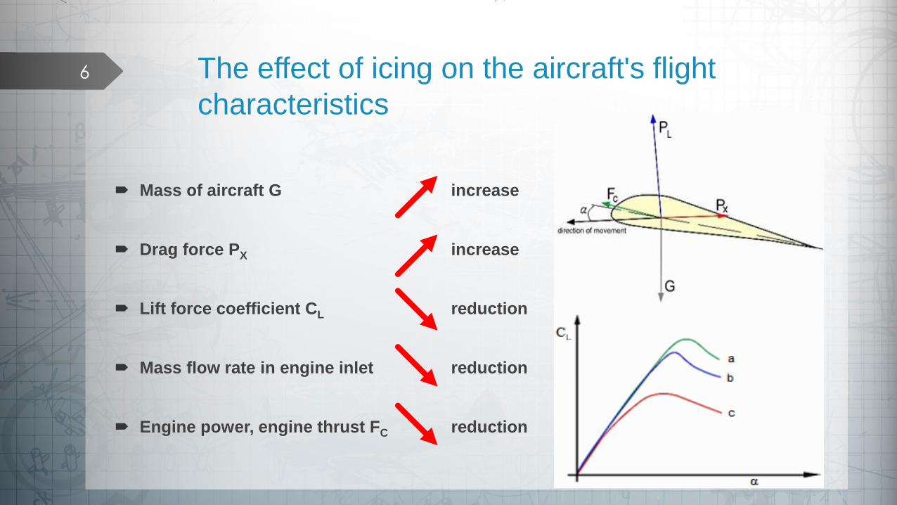
6 The effect of icing on the aircraft's flight
characteristics
Mass of aircraft G increase
Drag force PX increase
Lift force coefficient CL reduction
Mass flow rate in engine inlet reduction
Engine power, engine thrust FC reduction

7 Methodology: wing models
airfoil: NACA2410
chord: c=2.1 m
length: l=5 m
ice layer thickness: i=1 cm
ice density: ρi = 916 kg/m3
volume of ice coating: V1= 0.057041 m3
volume of ice coating: V2= 0.061021 m3
mass of ice: m1=52.29 kg
mass of ice: m2=55.94 kg
solid icing wing model
clean wing model
profile icing wing modelii Vm
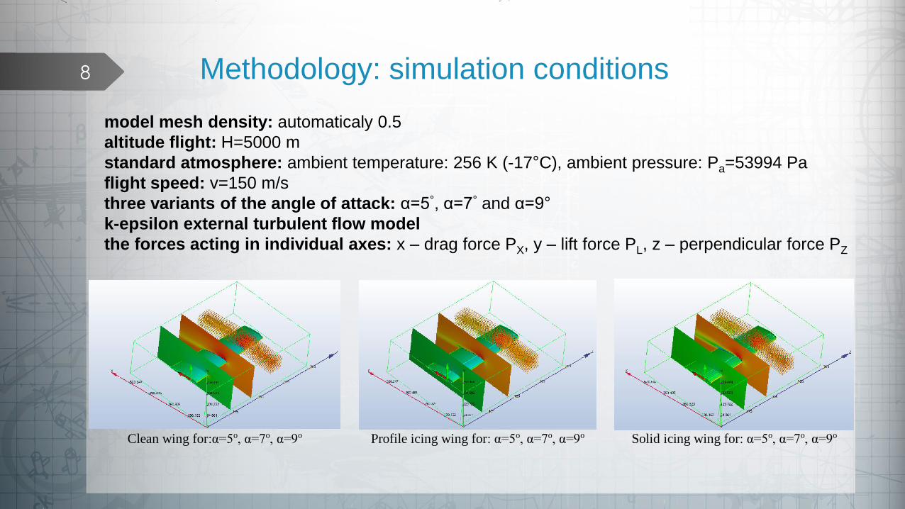
8 Methodology: simulation conditions
Clean wing for:α=5o, α=7o, α=9o Profile icing wing for: α=5o, α=7o, α=9o Solid icing wing for: α=5o, α=7o, α=9o
model mesh density: automaticaly 0.5
altitude flight: H=5000 m
standard atmosphere: ambient temperature: 256 K (-17°C), ambient pressure: Pa=53994 Pa
flight speed: v=150 m/s
three variants of the angle of attack: α=5°, α=7° and α=9°
k-epsilon external turbulent flow model
the forces acting in individual axes: x – drag force PX, y – lift force PL, z – perpendicular force PZ

9 ResultsNACA 2410 clean:
v=150 [m/s], ρa=0.7361 [kg/m3]
α=5o α=7o α=9o
S − Wing surface [m2] 16.47 16.47 16.47
PX – Resistance force [N] 4630.27 4349.82 3688.56
PL – Lift force [N] 24826.4 31560.8 37887
PZ – Perpendicular force [N] 248.12 245.47 209.2
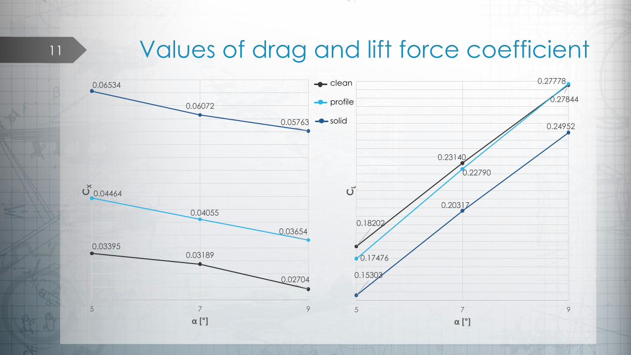
CX – Resistance force coefficient 0.03395 0.03189 0.02704
CL – Lift force coefficient 0.18202 0.2314 0.27778
NACA 2410 profile icing:
v=150 [m/s], ρa=0.7361 [kg/m3]
α=5o α=7o α=9o
S − Wing surface [m2] 21.96 21.96 21.96
PX – Resistance force [N] 6089.19 5530.48 4983.69
PL – Lift force [N] 23835.7 31084.2 37976.9
PZ – Perpendicular force [N] 4207.29 4149.18 4100.37
CX – Resistance force coefficient 0.04464 0.04055 0.03654
CL – Lift force coefficient 0.17476 0.2279 0.27844
NACA 2410 solid icing:
v=150 [m/s], ρa=0.7361 [kg/m3]
α=5o α=7o α=9o
S − Wing surface [m2] 22.26 22.26 22.26
PX – Resistance force [N] 8911.86 8282.44 7860.52
PL – Lift force [N] 20872.3 27710.9 34033
PZ – Perpendicular force [N] 4139.18 4078.76 4043.4
CX – Resistance force coefficient 0.06534 0.06072 0.05763
CL – Lift force coefficient 0.15303 0.20317 0.24952
2
2vSCP LL
2
2vSCP XXX
2
2vS
PC L
L
2
2vS
PC
X
XX
where:
PL – lift force [N]
CL – lift force coefficient [N]
PX – drag force [N]
CX – drag force coefficient [N]
ρ – air density [kg/m3]
S – wing surface [m2]
SX – surface of the projection of the body on a
plane perpendicular to the vector of the speed
of the body relative to the fluid [m2]
v – flight speed [m/s]

10 Values of drag and lift force
4630.274349.82
3688.56
6089.19
5530.48
4983.69
8911.86
8282.44
7860.52
2000
3000
4000
5000
6000
7000
8000
9000
10000
5 7 9
PX[N]
α [°]
24826.4
31560.8
37887
23835.7
31084.2
37976.9
20872.3
27710.9
34033
15000
18000
21000
24000
27000
30000
33000
36000
39000
42000
5 7 9
PL[N]
α [°]
clean
profile
solid
clean
profile
solid
11
0.033950.03189
0.02704
0.04464
0.04055
0.03654
0.06534
0.06072
0.05763
5 7 9
CX
α [°]
0.18202
0.23140
0.27778
0.17476
0.22790
0.27844
0.15303
0.20317
0.24952
5 7 9
CL
α [°]
Values of drag and lift force coefficientclean
profile
solid

12 Relative percentage increases in the value
of the drag and lift force in relation to the
drag and lift force value of the clean wing
31,51%27,14%
35,11%
92,47% 90,41%
113,11%
0%
20%
40%
60%
80%
100%
120%
5 7 9
PX[%]
α [°]
-4.16%
-1.53%
0%
-18.94%
-13.89%
-11.32%
-20%
-18%
-16%
-14%
-12%
-10%
-8%
-6%
-4%
-2%
0%
5 7 9
PL[%]
α [°]
profile
solid
profile
solid

13
Profile ice structure produces slightly lower values of lift force max -5 %
Profile icing leads to a significant increase in the value of drag force max 35 %
Solid icing significantly affects both the lift (max -19 %) and drag force (max113 %)
Already a centimeter of ice with a solid icing structure is the reason for the increase of the wing's drag force twice,
When increasing the value of the angle of attack for a profile ice wing, changes in the value of the generated lift force in relation
to the clean wing decreasing
Aircraft icing leading to increase the weight of the aircraft, increase the demand for the thrust force, which is tantamount to
increasing the fuel consumption of the aircraft engine
The icing phenomenon of the aircraft is a negative synergistic effect (the deterioration of the properties aerodynamic,
propulsion and pilot characteristics of the aircraft)
The results obtained during the simulation tests prove that 1 cm thick ice sheets effectively prevent further flight of the aircraft
and may cause an aircraft accident
Conclusions

14
Antonini, C., Innocenti, M., Horn, T., Marengo, M., Amirfazli, A., 2011. Understanding the effect of superhydrophobic coatings on energy reduction in anti-icing systems. Cold regions science and technology. Volume: 67. Issue: 1-2. Pages: 58-67. DOI: 10.1016/j.coldregions.2011.02.006.
Bragg, MB., Gregorek, GM., Lee, JD., 1986. Airfoil aerodynamics in icing conditions. Journal of aircraft. Volume: 23. Issue: 1. Pages: 76-81. DOI: 10.2514/3.45269.
Cebeci, T., Kafyeke, F., 2003. Aircraft icing. Annual review of fluid mechanics. Volume: 35. Pages: 11-21. DOI: 10.1146/annurev.fluid.35.101101.161217.
Chachurski R., Waślicki P., 2011. Instalacje przeciwoblodzeniowe i odladzające statków powietrznych. Prace Instytutu Lotnictwa 213. Warszawa.
Chachurski R., Waślicki P., 2011. Wykrywanie i sygnalizacja oblodzenia statków powietrznych. Prace Instytutu Lotnictwa 213. Warszawa.
Chen, J., Liu, J., He, M., Li, KY., Cui, DP., Zhang, QL., Zeng, XP., Zhang, YF., Wang, JJ., Song, YL., 2012. Superhydrophobic surfaces cannot reduce ice adhesion. Applied physics letters. Volume: 101. Issue: 11. Article Number: 111603. DOI: 10.1063/1.4752436.
Fortin, G., Laforte, JL., Ilinca, A., 2006. Heat and mass transfer during ice accretion on aircraft wings with an improved roughness model. International journal of thermal sciences. Volume: 45. Issue: 6. Pages: 595-606. DOI: 10.1016/j.ijthermalsci.2005.07.006.
Gębura A., Janusiak K., Paradowski M., 2014. Oblodzenie statku powietrznego – przyczyny, skutki, przeciwdziałanie. Journal of KONBiN 4(32)2014. ISSN 1895-8281. DOI 10.2478.
http://airfoiltools.com/airfoil. access 20.06.2018.
Lewitowicz J., Żyluk A., 2006. Podstawy eksploatacji statków powietrznych. TOM 5. Wydawnictwo Instytutu Technicznego Wojsk Lotniczych. Warszawa.
Liu, Y., Ma, LQ., Wang, W., Kota, AK., 2018. An experimental study on soft PDMS materials for aircraft icing mitigation. Applied surface science. Volume: 447. Pages: 599-609. DOI: 10.1016/j.apsusc.2018.04.032.
Milkiewicz A., Stepaniuk R., 2009. Praktyczna aerodynamika i mechanika lotu samolotu odrzutowego, w tym wysokomanewrowego. Wydawnictwo InstytutuTechnicznego Wojsk Lotniczych. Warszawa.
Pfitzenmaier, L., Unal, CMH., Dufournet, Y., Russchenberg, HWJ., 2018. Observing ice particle growth along fall streaks in mixed-phase clouds using spectral polarimetric radar data. Atmospheric chemistry and physics. Volume: 18. Issue: 11. Pages: 7843-7862. DOI: 10.5194/acp-18-7843-2018.
Szewczak, P., 2007. Meteorologia dla pilota samolotowego (PPL, CPL, ATPL, IR). Seria szkoleniowa ,,AVIA-TEST’’. Poznań.
Szutowski L., 2007. Poradnik pilota samolotowego. Seria szkoleniowa ,,AVIA-TEST’’. Poznań.
Wróbel M., 2008. Zjawisko i rodzaje oblodzenia profili łopat oraz struktury śmigłowca. Prace Instytutu Lotnictwa, Nr 3-4, Pages: 340-346, PZL Świdnik S. A.
Bibliography
Thank you for your attention