ETV 0855 - SIGMATEK
44
ETV 0855 Control Panel Date of creation: 20.04.2013 Version date: 27.04.2016 Article number: 13-230-0855-E
Transcript of ETV 0855 - SIGMATEK

ETV 0855
Control Panel
Date of creation: 20.04.2013 Version date: 27.04.2016 Article number: 13-230-0855-E
Publisher: SIGMATEK GmbH & Co KG
A-5112 Lamprechtshausen
Tel.: 06274/4321
Fax: 06274/4321-18
Email: [email protected]
WWW.SIGMATEK-AUTOMATION.COM
Copyright © 2013
SIGMATEK GmbH & Co KG
Translation from German
All rights reserved. No part of this work may be reproduced, edited using an electronic system, duplicated or dis-
tributed in any form (print, photocopy, microfilm or in any other process) without the express permission.
We reserve the right to make changes in the content without notice. The SIGMATEK GmbH & Co KG is not responsi-
ble for technical or printing errors in the handbook and assumes no responsibility for damages that occur through
use of this handbook.

CONTROL PANEL ETV 855
27.04.2016 Page 1
Control Panel ETV 0855
The control panel is an intelligent terminal for programming and visualization of automated processes. Process diagnosis as well as operating and monitoring automated procedures is simplified using this terminal.
A touch screen serves as the input medium for process data and parameters. The output is shown on an 8.4" SVGA TFT color display.
With the LSE mask editor, graphics can be created on the PC, then stored and displayed on the terminal.
The available interface connections can be used to exchange process data or configure the terminal. A micro SD card serves as the storage medium for the operating system, applica-tion and application data.
The integrated, high-performance VARAN bus can be used to control I/O modules directly.

ETV 0855 CONTROL PANEL
Page 2 27.04.2016
Contents
1 Technical Data ......................................................................... 5
1.1 Performance Data ......................................................................... 5
1.2 Electrical Requirements ............................................................... 6
1.3 Terminal ......................................................................................... 6
1.4 Environmental Conditions ........................................................... 6
1.5 8.7" SVGA Display ........................................................................ 7
1.6 Control Unit ................................................................................... 7
1.7 Digital Outputs .............................................................................. 8
1.8 Digital Inputs ................................................................................. 8
1.9 Miscellaneous ............................................................................... 8
2 Mechanical Dimensions .......................................................... 9
3 Chemical Resistance ............................................................ 10
3.1 Decorative Foil ............................................................................ 10
4 Connector Layout .................................................................. 11
4.1 Front ............................................................................................. 11
4.2 Rear and Bottom ......................................................................... 12
4.3 Applicable connectors ............................................................... 16
5 Buffer Battery ........................................................................ 17
5.1 Exchanging the Battery .............................................................. 18
6 BIOS ....................................................................................... 20

CONTROL PANEL ETV 855
27.04.2016 Page 3
7 Cooling ................................................................................... 20
8 Mounting Instructions ........................................................... 20
9 Wiring Guidelines .................................................................. 21
9.1 Earth Connection ........................................................................ 21
9.2 Shielding ...................................................................................... 21
9.3 ESD Protection ............................................................................ 21
9.4 USB Interface Connections ....................................................... 21
10 CAN Bus Setup ...................................................................... 22
10.1 CAN Bus Station Number .......................................................... 22
10.2 CAN Bus Data Transfer Rate ..................................................... 22
10.3 CAN Bus Termination ................................................................. 23
11 Process Diagram ................................................................... 24
12 Status and Error Messages .................................................. 25
13 Application exceptions ......................................................... 33
13.1 SRAM and IRQ routines ............................................................. 33
13.2 SRAM and consistency of changed data ................................. 33
13.3 The file system does not support safe writing through SRAM ...................................................................................................... 33
13.4 Data Breakpoint .......................................................................... 33
14 Note: SRAM Function ........................................................... 34

ETV 0855 CONTROL PANEL
Page 4 27.04.2016
15 Recommended Shielding for VARAN .................................. 35
15.1 Wiring from the Control Cabinet to an External VARAN Component .................................................................................. 36
15.2 Wiring Outside of the Control Cabinet ..................................... 37
15.3 Shielding for Wiring Within the Control Cabinet ..................... 38
15.4 Connecting Noise-Generating Components ............................ 39
15.5 Shielding Between Two Control Cabinets ............................... 40
16 Cleaning the Touch Screen .................................................. 41
CONTROL PANEL ETV 855
27.04.2016 Page 5
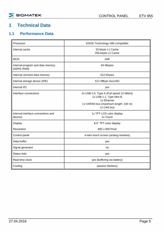
1 Technical Data
1.1 Performance Data
Processor EDGE-Technology X86 compatible
Internal cache 32-kbyte L1 Cache
256-kbyte L2 Cache
BIOS AMI
Internal program and data memory
(DDR2 RAM)
64 Mbytes
Internal remnant data memory 512 Kbytes
Internal storage device (IDE) 512 MByte microSD
Internal I/O yes
Interface connections 2x USB 2.0, Type A (Full speed 12 Mbit/s)
1x USB 1.1, Type Mini B
1x Ethernet
1x VARAN bus (maximum length: 100 m)
1x CAN bus
Internal interface connections and
devices
1x TFT-LCD color display
1x Touch
Display
Resolution
8.4“ TFT color display
800 x 600 Pixel
Control panel 4-wire touch screen (analog resistive)
Data buffer yes
Signal generator no
Status leds yes
Real-time clock yes (buffering via battery)
Cooling passive (fanless)

ETV 0855 CONTROL PANEL
Page 6 27.04.2016
1.2 Electrical Requirements
Supply voltage typically +24 V DC
minimum +18 V DC maximum +30 V DC
Current consumption of the supply
(+24 V)
typically 400 mA
(with no external devices connected)
maximum 450 mA
(with external devices connected)
Starting current maximum 27 A for 9 µs
The device shall be supplied from an isolating transformer having a secondary listed fuse rated either: a) max. 5 amps for voltages 0~20 V (0~28.3 Vp), or b) 100 VA/Vp for voltages of 20~30 V (28.3~42.4 Vp).
1.3 Terminal
Dimensions 240 mm / 200 mm / 40.5 mm (W x H x D)
Material front plate: 3.5 mm anodized aluminum
Weight typically 1.5 kg
1.4 Environmental Conditions
Storage temperature -10 – +85 °C
Operating temperature 0 – 50 °C
Humidity 10 - 90 %, uncondensed
EMV stability EN 61000-6-2: noise resistance
EN 61000-6-4: noise emission
Vibration tolerance EN 60068-2-6 2 – 9 Hz: amplitude 3.5 mm
9 – 200 Hz: 1 g (10 m/s²)
Shock resistance EN 60068-2-27 150 m/s²
Protection type EN 60529
protection through housing
Front: IP54
Cover: IP20
CONTROL PANEL ETV 855
27.04.2016 Page 7
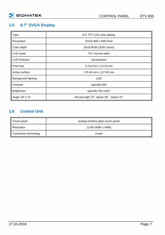
1.5 8.7" SVGA Display
Type 8.4” TFT LCD color display
Resolution SVGA 800 x 600 Pixel
Color depth 18-bit RGB (262K colors)
LCD mode TN / normal white
LCD Polarizer transmissive
Pixel size 0.213 mm x 0.213 mm
Active surface 170.40 mm x 127.80 mm
Background lighting LED
Contrast typically 600
Brightness typically 250 cd/m²
Angle CR ≥ 10 left and right 75°, above 60° , below 70°
1.6 Control Unit
Touch panel analog resistive glass touch panel
Resolution 12-Bit (4096 x 4096)
Connection technology 4-wire

ETV 0855 CONTROL PANEL
Page 8 27.04.2016
1.7 Digital Outputs
Number of … 8
Short-circuit proof yes
Maximum continuous
current load allowed per
channel
2 A
Maximum total current
(all 8-channels)
6 A (100 % of on-time)
Voltage drop over power
supply (output active)
1 V
Residual output current
(inactive)
12 µA
Turn-on delay < 400 s
Turn-off delay < 400 s
Max. braking energy of
inductive loads
1 channel 0.12 [Joules]
1.8 Digital Inputs
Number of … 8
Input voltage typically +24 V maximum +30 V
Signal level low: < +4.5 V high : > +14 V
Switching threshold typically +11 V
Input current typically 5 mA at + 24 V
Input delay typically 5 ms
1.9 Miscellaneous
Article number 12-230-0855
Hardware version 1.x

CONTROL PANEL ETV 855
27.04.2016 Page 9
2 Mechanical Dimensions

ETV 0855 CONTROL PANEL
Page 10 27.04.2016
3 Chemical Resistance
3.1 Decorative Foil
Solution Effect over time
1 hour 24 hours
Methyl, ethyl, ketone None None
Cyklohexanol None None
Acetone None None
Ethanol None None
Benzyl alcohol Yes Yes
1.1.1.Trichlorethan (Genklene) None None
Perchloroethylene (Perklone) None None
Trichloroethylene None None
Methylene chloride Yes Yes
Diethyl ether None None
Toluene None None
Xylene None None
Benzine None None
Diesel oil None None
Nitric acid < 10 % None None
Sodium hydroxide < 10 % None None
Turpentine None None
Ethyl acetate None None

CONTROL PANEL ETV 855
27.04.2016 Page 11
4 Connector Layout
4.1 Front
USB 2.0 (Type A, Full Speed 12 Mbit/s)
Status Displays
LED status Definition
LED error lights red BIOS is booted
LED error blinks read Error status / operating system boot process
LED DC lights green DC OK
Pin Function
1 +5 V 2 D0- 3 D0+ 4 GND
ETV 0855 CONTROL PANEL
Page 12 27.04.2016
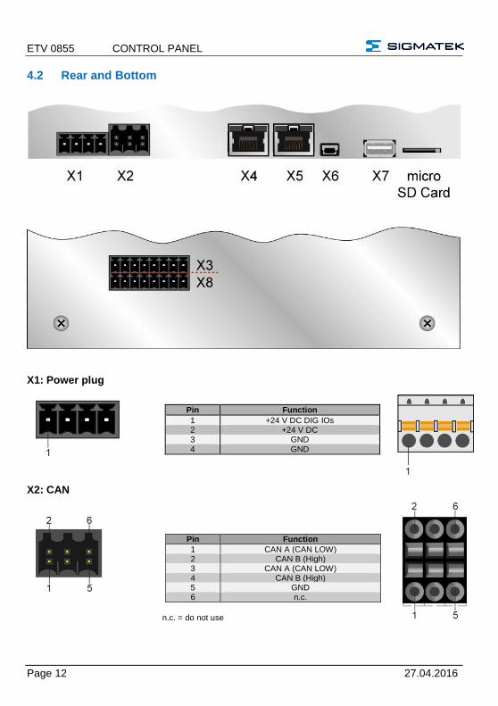
4.2 Rear and Bottom
X1: Power plug
X2: CAN
n.c. = do not use
Pin Function
1 +24 V DC DIG IOs 2 +24 V DC 3 GND 4 GND
Pin Function
1 CAN A (CAN LOW) 2 CAN B (High) 3 CAN A (CAN LOW) 4 CAN B (High) 5 GND 6 n.c.

CONTROL PANEL ETV 855
27.04.2016 Page 13
X3 and X8: 8 digital inputs, 8 digital outputs
Pin Function
1 Output 1 2 Output 2 3 Output 3 4 Output 4 5 Input 1 6 Input 2 7 Input 3 8 Input 4
Pin Function
1 Output 5 2 Output 6 3 Output 7 4 Output 8 5 Input 5 6 Input 6 7 Input 7
8 Input 8
X3: Pin assignment
X8: Pin assignment
ETV 0855 CONTROL PANEL
Page 14 27.04.2016
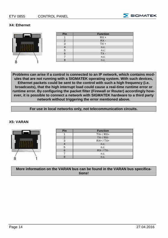
X4: Ethernet
Problems can arise if a control is connected to an IP network, which contains mod-ules that are not running with a SIGMATEK operating system. With such devices,
Ethernet packets could be sent to the control with such a high frequency (i.e. broadcasts), that the high interrupt load could cause a real-time runtime error or
runtime error. By configuring the packet filter (Firewall or Router) accordingly how-ever, it is possible to connect a network with SIGMATEK hardware to a third party
network without triggering the error mentioned above.
For use in local networks only, not telecommunication circuits.
X5: VARAN
More information on the VARAN bus can be found in the VARAN bus specifica-tions!
Pin Function
1 RX + 2 RX - 3 TX + 4 n.c. 5 n.c. 6 TX - 7 n.c. 8 n.c.
Pin Function
1 TX+ / RX+ 2 TX- / RX- 3 RX+ / TX+ 4 n.c. 5 n.c. 6 RX- / TX- 7 n.c. 8 n.c.
CONTROL PANEL ETV 855
27.04.2016 Page 15
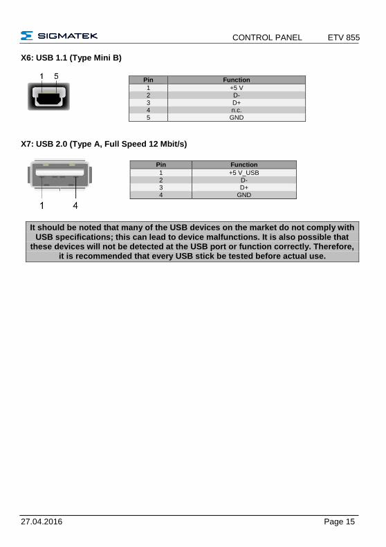
X6: USB 1.1 (Type Mini B)
X7: USB 2.0 (Type A, Full Speed 12 Mbit/s)
It should be noted that many of the USB devices on the market do not comply with USB specifications; this can lead to device malfunctions. It is also possible that
these devices will not be detected at the USB port or function correctly. Therefore, it is recommended that every USB stick be tested before actual use.
Pin Function
1 +5 V 2 D- 3 D+ 4 n.c. 5 GND
Pin Function
1 +5 V_USB 2 D- 3 D+ 4 GND

ETV 0855 CONTROL PANEL
Page 16 27.04.2016
microSD Card
It is recommended that only storage media provided by SIGMATEK (CompactFlash cards, microSD cards etc.) be used.
Order number for the 512-Mbyte EDGE microSD card: 12-630-051
The number of read and write actions have a significant influence on the lifespan of the storage media.
Il est recommandé de n’utiliser que les supports de stockage approuvés par SIGMATEK (compact flash, microSD, etc.).
Numéro de commande pour la carte microSD 512 Mo Edge est le: 12-630-051
Le nombre de cycles de lecture et d'écriture a l’influence notable sur la durée de vie des supports de stockage.
4.3 Applicable connectors
CAN-Bus: 6-pin Weidmüller plug, B2L3, 5/6 USB: 4-pin, type A (downstream connector) Ethernet: 8-pin, RJ45 VARAN: 8-pin, RJ45 Power supply: 4-pin Phoenix plug with spring terminal FK-MCP1, 5/4-ST-3.5 Digital I/Os: 2 x 8-pin Phoenix plug with spring terminal FMC1, 5/8-ST-3.5
The complete CKL 213 connector set is available from SIGMATEK under the article number 12-600-213.
Pin Function
1 DAT2 2 CD/DAT3 3 CMD 4 +3V3 5 Clk 6 GND 7 DAT0 8 DAT1
CONTROL PANEL ETV 855
27.04.2016 Page 17
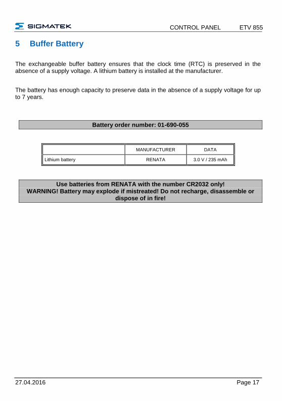
5 Buffer Battery
The exchangeable buffer battery ensures that the clock time (RTC) is preserved in the absence of a supply voltage. A lithium battery is installed at the manufacturer.
The battery has enough capacity to preserve data in the absence of a supply voltage for up to 7 years.
Battery order number: 01-690-055
MANUFACTURER DATA
Lithium battery RENATA 3.0 V / 235 mAh
Use batteries from RENATA with the number CR2032 only! WARNING! Battery may explode if mistreated! Do not recharge, disassemble or
dispose of in fire!

ETV 0855 CONTROL PANEL
Page 18 27.04.2016
5.1 Exchanging the Battery
1. Disconnect the power to the ETV. 2. Open the locking screws on the back f the terminal with a PH-1 screwdriver:

CONTROL PANEL ETV 855
27.04.2016 Page 19
3. Lift rear panel of the terminal: 4. Using the strap, remove the battery the holder (see arrow). 5. Insert the new battery with the correct polarity and close the terminal. (+ Pole toward the backside)
4. Using the strap, remove the battery from the holder (see arrow). 5. Place the new battery in the holder with the correct polarity (+ Pole toward the frontside)
and replace the cover.

ETV 0855 CONTROL PANEL
Page 20 27.04.2016
6 BIOS
The BIOS is configured so that the LASAL operating system is booted from the SD card.
7 Cooling
The terminal's power loss can reach up to 10 Watts. To ensure the necessary air circulation for cooling, the following mounting instructions must be followed!
8 Mounting Instructions
The following clearance is required for the cover:
- Rear side, left and right 5 cm - Above and below 10 cm
A mounting position of 60° to 120° is also required.

CONTROL PANEL ETV 855
27.04.2016 Page 21
9 Wiring Guidelines
9.1 Earth Connection
The terminal must be connected to earth through the mounting on control cabinet or over the terminal provided. It is important to create a low-ohm earth connection, only then can error-free operation be guaranteed. The earth connection should have the maximum cross section and the largest electrical surface possible.
9.2 Shielding
With Ethernet, a CAT-5 cable with shielded RJ45 connectors is required. The shielding in the CAT-5 cable is connected to earth through the RJ45 connector. Noise therefore cannot reach the electronics and affect the function.
9.3 ESD Protection
Typically, USB devices (keyboard, mouse) are not equipped with shielded cables. These devices are disrupted by ESD and in some instances, no longer function.
Before any device is connected to or disconnected from the terminal, the potential should be equalized (by touching control cabinet or earth terminal). Electrostatic loads (through clothing and shoes) can thereby be dissipated.
9.4 USB Interface Connections
The terminal has a USB interface connection that can used to connect various USB devices (keyboard, mouse, storage media, hubs, etc.) in LASAL. Several USB devices, which are fully functional in LASAL, can be connected using a hub.

ETV 0855 CONTROL PANEL
Page 22 27.04.2016
10 CAN Bus Setup
This section explains how to correctly configure the CAN bus. The following parameters must first be set: Station number and data transfer rate.
10.1 CAN Bus Station Number
Each CAN bus station is assigned its own station number. With this station number, data can be exchanged with other stations connected to the bus. Up to 31 stations can be in-stalled in a CAN bus system. However, each station number can only be assigned once.
10.2 CAN Bus Data Transfer Rate
The data transfer rate (baud rate) for the CAN bus can be set. However, the longer the length of the bus, the smaller the transfer rate that must be selected.
VALUE Baud rate Maximum length
0 615 kBit/s 60 m
1 500 kBit/s 80 m
2 250 kBit/s 160 m
3 125 kBit/s 320 m
4 100 kBit/s 400 m
5 50 kBit/s 800 m
6 20 kBit/s 1200 m
7 1 Mbit / s 30 m
These values are valid for the following cable: 120 , Twisted Pair.
NOTE: For the CAN bus protocol: 1 kBit/ s = 1 kBaud.

CONTROL PANEL ETV 855
27.04.2016 Page 23
10.3 CAN Bus Termination
In a CAN bus system, both end modules must be terminated. This is necessary to avoid transmission errors caused by reflections in the line.
Device 1 Device 2 Device 3 Device n
e.g. CPUDCP 160
e.g. TerminalET 081
CAN bus connection
CAN bustermination on theclamp module
DSUB plug withterminationcircuit
e.g. TerminalETV 0855-1
If the terminal is an end module, it can be terminated by placing a 150-Ohm resistor between CAN-A (Low) and CAN-B (High).

ETV 0855 CONTROL PANEL
Page 24 27.04.2016
11 Process Diagram

CONTROL PANEL ETV 855
27.04.2016 Page 25
12 Status and Error Messages
Status and error messages are displayed in the LASAL Class software status test. POINTER or CHKSUM messages can also be shown on the terminal screen.
Number Message Definition Cause/solution
00 RUN RAM The user program is currently running in RAM.
The display is not affected.
Info
01 RUN ROM The user program in the program memory module was loaded into the
RAM and is currently being run.
The display is not affected.
Info
02 RUNTIME The total duration of all cyclic objects exceeds the maximum time; the time can be configured using 2 system variables:
- Runtime: time remaining
- SWRuntime: pre-selected value for the runtime counter
Optimize the application's cyclic task.
Use higher capacity CPU
Configure preset value
03 POINTER Incorrect program pointers were detect-ed before running the user program
Possible Causes:
- The program memory module is missing, not programmed or defect.
- The program in the user program memory (RAM) is not executable.
- The buffering battery has failed.
- The user program has over-written a software error.
Solution:
- Reprogram the memory module, if the error reoccurs ex-change the module.
- Exchange the buffering battery
- Correct programming error
04 CHKSUM Before running the user program, a false checksum was detected.
Cause/solution: s. POINTER

ETV 0855 CONTROL PANEL
Page 26 27.04.2016
05 Watchdog The program was interrupted through the watchdog logic.
Possible Causes:
- Interrupts the user program blocked of a long time period (STI instruction forgotten)
- Programming error in a hardware interrupt.
- INB, OUTB, INW, OUTW instruc-tions used incorrectly.
- The processor is defect.
Solution:
- Correct programming error.
- Exchange CPU.
06 GENERAL ERROR General error
Stopping the application from the online interface has failed.
This error occurs during the devel-opment stage of operating system only.
07 PROM DEFECT An error has occurred while program-ming the memory module.
Cause:
- The program memory module is defect.
- The user program is too large.
- The program memory module is missing.
Solution:
- Exchange the program memory module
08 Reset The CPU has received the reset signal and is waiting for further instructions.
The user program is not processed.
Info
09 WD DEFEKT The hardware monitoring circuit (watch-dog logic) is defect.
After power-up, the CPU checks the watchdog logic function. If an error occurs during this test, the CPU deliber-ately enters an infinite loop from which no further instructions are accepted.
Solution: Exchange CPU.
10 STOP The program was stopped by the pro-gramming system.
11 PROG BUSY Reserved
12 PROGRAM LENGTH Reserved

CONTROL PANEL ETV 855
27.04.2016 Page 27
13 PROG END The memory module was successfully completed.
Info
14 PROG MEMO The CPU is currently programming the memory module.
Info
15 STOP BRKPT The CPU was stopped by a breakpoint in the program.
Info
16 CPU STOP The CPU was stopped by the program-ming software.
Info
17 INT ERROR The CPU has triggered a false interrupt and stopped the user program or has encountered an unknown instruction while running the program.
Cause:
- A nonexistent operating system was used.
- Stack error (uneven number of PUSH and POP instructions).
- The user program was interrupt-ed by a software error.
Solution:
- Correct programming error.
18 SINGLE STEP The CPU is in single step mode and is waiting for further instructions.
Info
19 Ready A module or project has been sent to the CPU and it is ready to run the program.
Info
20 LOAD The program has stopped and is receiv-ing a module or project.
Info
21 UNZUL. Modul The CPU has received a module, which does not belong to the project.
Solution:
- Recompile and download the entire project
22 MEMORY FULL The operating system memory /Heap) is too small. No more memory could be reserved, when an internal or interface function was called from the application.
Cause:
- Memory is only allocated bun not released.
Solution
Clear memory
23 NOT LINKED When starting the CPU, a missing module or a module that does not belong to the project was detected.
Solution:
- Recompile and download the entire project
24 DIV BY 0 A division error has occurred. Possible Causes:
- Division by 0.
- The result of a division does not fit in the result register.
Solution: - Correct programming error.
ETV 0855 CONTROL PANEL
Page 28 27.04.2016
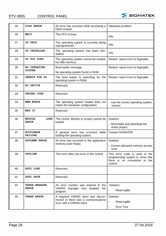
25 DIAS ERROR An error has occurred while accessing a DIAS module.
Hardware problem
26 WAIT The CPU is busy. Info
27 OP PROG The operating system is currently being reprogrammed. Info
28 OP INSTALLED The operating system has been rein-stalled. Info
29 OS TOO LONG The operating system cannot be loaded; too little memory.
Restart; report error to Sigmatek.
30 NO OPERATING
SYSTEM Boot loader message.
No operating system found in RAM.
Restart; report error to Sigmatek.
31 SEARCH FOR OS The boot loader is searching for the operating system in RAM.
Restart; report error to Sigmatek.
32 NO DEVICE Reserved
33 UNUSED CODE Reserved
34 MEM ERROR The operating system loaded does not match the hardware configuration.
- Use the correct operating system version
35 MAX IO Reserved
36 MODULE LOAD
ERROR The LASAL Module or project cannot be loaded.
Solution:
- Recompile and download the entire project
37 BOOTIMAGE
FAILURE A general error has occurred while loading the operating system.
Contact SIGMATEK
38 APPLMEM ERROR An error has occurred in the application memory (user heap).
Solution:
- Correct allocated memory access error
39 OFFLINE This error does not occur in the control. This error code is used in the programming system to show that there is no connection to the control.
40 APPL LOAD Reserved
41 APPL SAVE Reserved
44 VARAN MANAGER
ERROR An error number was entered In the VARAN manager and stopped the program.
Solution:
- Read logfile
45 VARAN ERROR A required VARAN client was discon-nected or there was a communications error with a VARAN client.
Solution:
- Read logfile
- Error Tree

CONTROL PANEL ETV 855
27.04.2016 Page 29
46 APPL-LOAD-ERROR An error has occurred while loading the application.
Cause:
- Application was deleted.
Solution:
- Reload the application into the control.
47 APPL-SAVE-ERROR An error has occurred while attempting to save the application.
50 ACCESS-
EXCEPTION-ERROR Read or write access of a restricted memory area. (I.e. writing to the NULL pointer).
Solution:
- Correct application errors
51 BOUND EXCEEDED An exception error has occurred when accessing arrays. The memory area was overwritten through accessing an invalid element.
Solution:
- Correct application errors
52 PRIVILEDGED
INSTRUCTION An invalid instruction for the CPU level, i.e. setting the segment register.
Cause:
- The application has overwritten the application program code.
Solution:
- Correct application errors
53 FLOATING POINT
ERROR
An error has occurred during a floating-point operation.
60 DIAS-RISC-ERROR Error from the Intelligent DIASMaster. Restart; report error to Sigmatek.
64 INTERNAL ERROR An internal error has occurred, all appli-cations are stopped.
Restart; report error to Sigmatek.
65 FILE ERROR An error has occurred during a file operation.
66 DEBUG ASSERTION
FAILED Internal error. Restart; report error to Sigmatek.
67 REALTIME RUNTIME The total duration of all real-time objects exceeds the maximum time; the time cannot be configured.
2 ms for 386 CPUs
1 ms for all other CPUs
Solution:
- Optimize the application's realtime task (RtWork).
- Reduce the clock time for the realtime task of all objects.
- Correct application errors
- CPU is overloaded in realtime => use a higher capacity CPU.
68 BACKGROUND
RUNTIME The total duration of all background objects exceeds the maximum time; the time can be configured using 2 system variables:
-BTRuntime: time remaining
-SWBTRuntime: pre-selected value for the runtime counter
Solution:
- Optimize the application's back-ground task (background)
- Use higher capacity CPU
- Set SWBTRuntime correctly.

ETV 0855 CONTROL PANEL
Page 30 27.04.2016
70 C-DIAS ERROR An error occurred in connection with a C-DIAS module.
Cause:
- The reason for this error is documented in the log file
Solution:
- Depends on the cause
72 S-DIAS ERROR A connection error with a S-DIAS mod-ule has occurred.
Possible causes:
- real network does not match the project
- S-DIAS client is defective
Solution:
- analyze logfile
75 SRAM ERROR Only EDGE CPUs
An error occurred while initializing, reading or writing SRAM data.
Possible causes:
- - SRAM configured incorrectly
- - SD card formatted incorrectly
- - SD card removed
Solution:
- - evaluate log file (Event00.log)
- - check configuration
- - format SD card as EDGE medium with Lasal Class 2
- - check SD card
95 USER DEFINED 0 User-definable code.
96 USER DEFINED 1 User-definable code.
97 USER DEFINED 2 User-definable code.
98 USER DEFINED 3 User-definable code.
99 USER DEFINED 4 User-definable code.
100 C_INIT Initialization start; the configuration is run.
101 C_RUNRAM The LASAL project was successfully started from RAM.
102 C_RUNROM The LASAL project was successfully started from ROM.
103 C_RUNTIME
104 C_READY The CPU is ready for operation.
105 C_OK The CPU is ready for operation.
106 C_UNKNOWN_CID An unknown class from a stand-along or embedded object: unknown base class.

CONTROL PANEL ETV 855
27.04.2016 Page 31
107 C_UNKNOWN_CONSTR The operating system class cannot be created; the operating system is proba-bly wrong.
108 C_UNKNOWN_OBJECT Reference to an unknown object in an interpreter program, creation of more than one DCC080 object.
109 C_UNKNOWN_CHNL The hardware module number is greater than 60.
110 C_WRONG_CONNECT No connection to the required channels.
111 C_WRONG_ATTR Wrong server attribute.
112 C_SYNTAX_ERROR No specific error, recompile all and reload project components.
113 C_NO_FILE_OPEN An attempt was made to open an un-known table.
114 C_OUTOF_NEAR Memory allocation error
115 C_OUT OF_FAR Memory allocation error
116 C_INCOMAPTIBLE An object with the same name exists but has another class.
117 C_COMPATIBLE An object with the same name and class exists but must be updated.
224 LINKING The application is currently linking.
225 LINKING ERROR An error has occurred while linking. An error messaged is generated in the LASAL status window.
226 LINKING DONE Linking is complete.
230 OP BURN The operating system is currently being burned into the Flash memory.
231 OP BURN FAIL An error has occurred while burning the operating system.
232 OP INSTALL The operating system is currently being installed.
240 USV-WAIT The power supply was disconnected; the UPS is active.
The system is shutdown.
241 Reboot The operating system is restarted.
242 LSL SAVE
243 LSL LOAD
252 CONTINUE

ETV 0855 CONTROL PANEL
Page 32 27.04.2016
253 PRERUN The application is started.
254 PRERESET The application is ended.
255 CONNECTION BREAK
CONTROL PANEL ETV 855
27.04.2016 Page 33
13 Application exceptions
13.1 SRAM and IRQ routines
Writing remnant data during interrupt routines is not allowed and leads to a system crash.
13.2 SRAM and consistency of changed data
If more than 32 different sectors are changed (512 bytes each) shortly before shutting down the voltage supply while the user program is writing to the Micro SD card, this can some-times lead to partial loss of remnant data.
13.3 The file system does not support safe writing through SRAM
If files are stored, modified or written on the Micro SD card from the user program, these files must always be stored with a fixed maximum size. Since changes in size and the sim-ultaneous shutdown of the voltage supply can corrupt the file system, a later change in the file size is not allowed.
13.4 Data Breakpoint
This CPU does not support the data breakpoint is a feature.

ETV 0855 CONTROL PANEL
Page 34 27.04.2016
14 Note: SRAM Function
Due to the fact that the SRAM (remnant memory) is emulated through the µSD card, two different mechanisms are available to save changed SRAM data on the µSD card:
1. Writing only in the event of PowerFail with a backup time buffered through the hardware (starting with version 01.02.195).
2. Writing cyclically when data is changed
With cyclical writing, the entire 512 kB of SRAM can be used. Depending on the number and frequency of the SRAM data written from the user program however, the life span of the µSD card can be significantly reduced.
To eliminate the dependency on the number and frequency of changed SRAM data, it his strongly recommended to set the SRAM emulation to the PowerFail mechanism. The
SRAM data is thereby written during shut down or a reset, a cyclic load is eliminated. This mechanism limits the amount of SRAM that can be used to 16 kbytes, whereby, the opera-ting system requires 4 bytes to backup the Event log files. 12 kbytes therefore remain for the user; this corresponds to approximately 3000 SRAM values.
With the following settings in the operating system, the SRAM is changed to the PowerFail mechanism with 16 kbytes SRAM. Detailed information on the SRAM Response can be found in the LASAL OS document under the chapter "SRAM".
In the file “c:\autoexec.lsl“: SETENV SRAMFORMAT 2
In the file „c:\lslsys\config.lsl“: SramSize=16384
SramdiskFullCopyAtPowerdown=1
SysSramSize=4096
In the LASAL CLASS project, seldom changed value settings can be converted to file stor-age in retentive servers as well as in RamEx and StringRam objects. If existing objects are converted to File from SRAM, the loader version 02.02.140 or higher must be used, as well as the RamEx and StringRam classes of the Tools library version 01.02.033 or higher.
For cyclic writing to files from the user program, the LASAL CLASS provides the "Flash Media Lifetime calculation" tool, with which the life span calculation for the different write-scenarios can be set.

CONTROL PANEL ETV 855
27.04.2016 Page 35
15 Recommended Shielding for VARAN
The real-time VARAN Ethernet bus system exhibits very robust characteristics in industrial environments. Through the use of IEEE 802.3 standard Ethernet physics, the potentials between an Ethernet line and sending/receiving components are separated. Messages to a bus participant are immediately repeated by the VARAN Manager in the event of an error. The shielding described below is principally recommended.
For applications in which the bus is run outside the control cabinet, the correct shielding is required. Especially when for structural reasons, the bus line must be placed next to strong electromagnetic interference. It is recommended to avoid placing Varan bus lines parallel to power cables whenever possible.
SIGMATEK recommends the use of CAT5e industrial Ethernet bus cables.
For the shielding, an S-FTP cable should be used.
An S-FTP bus is a symmetric, multi-wire cable with unshielded pairs. For the total shielding, a combination of foil and braiding is used. A non-laminated variant is recommended.
The VARAN cable must be secured at a maximum distance of 20 cm from the con-nector to protect against vibration!

ETV 0855 CONTROL PANEL
Page 36 27.04.2016
15.1 Wiring from the Control Cabinet to an External VARAN Component
If the Ethernet lines are connected from a VARAN component to a VARAN node located outside the control cabinet, the shielding should be placed at the entry point to the control cabinet housing. All noise can then be dissipated before reaching the electronic compo-nents.

CONTROL PANEL ETV 855
27.04.2016 Page 37
15.2 Wiring Outside of the Control Cabinet
If a VARAN bus cable must be placed outside of the control cabinet only, no additional shield connection is required. This requires that only IP67 modules and connectors be used. These components are very robust and noise resistant. The shielding for all sockets in IP67 modules are internally connected to common bus or electrically connected to the housing, whereby the deflection of voltage spikes does not flow through the electronics.

ETV 0855 CONTROL PANEL
Page 38 27.04.2016
15.3 Shielding for Wiring Within the Control Cabinet
Sources of strong electromagnetic noise located within the control cabinet (drives, Trans-formers, etc.) can induce interference in a VARAN bus line. Voltage spikes are dissipated over the metallic housing of a RJ45 connector. Noise is conducted over the control cabinet without additional measures needed on the circuit board of electronic components. To avoid error sources with data exchange, it is recommended that shielding be placed before any electronic components in the control cabinet.
CONTROL PANEL ETV 855
27.04.2016 Page 39
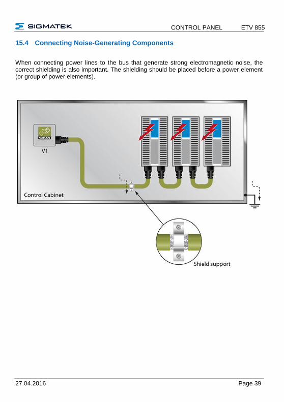
15.4 Connecting Noise-Generating Components
When connecting power lines to the bus that generate strong electromagnetic noise, the correct shielding is also important. The shielding should be placed before a power element (or group of power elements).

ETV 0855 CONTROL PANEL
Page 40 27.04.2016
15.5 Shielding Between Two Control Cabinets
If two control cabinets must be connected over a VARAN bus, it is recommended that the shielding be located at the entry points of each cabinet. Noise is therefore prevented from reaching the electronic components in both cabinets.

CONTROL PANEL ETV 855
27.04.2016 Page 41
16 Cleaning the Touch Screen
CAUTION! Before cleaning the touch screen, the terminal must first be turned off to avoid un-
intentionally triggering functions or commands!
The terminal's touch screen can only be cleaned with a soft, damp cloth. To dampen the cloth, a screen-cleaning solution such as an antistatic foam, water with detergent or alcohol should be used. First spray the cleaning fluid on the cloth and not directly on the terminal. The cleaning solution should not be allowed to reach the terminal electronics, for example, through the ventilation slots.
No erosive cleaning solutions, chemicals, abrasive cleansers or hard objects that can scratch or damage the touch screen may be used.
If the terminal comes in contact with toxic or erosive chemicals, clean the terminal immedi-ately and with caution to prevent acid damage.
To ensure the optimal function of the terminal, the touch screen should be cleaned at regular intervals!
To extend the lifespan of the touch screen as much as possible, using the fingers to operate the terminal is recommended.
ETV 0855 CONTROL PANEL
Page 42 27.04.2016
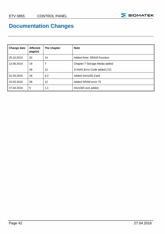
Documentation Changes
Change date Affected
page(s)
The chapter Note
25.10.2013 32 14 Added Note: SRAM Function
12.06.2014 19
29
7
12
Chapter 7 Storage Media added
S-DIAS Error Code added (72)
31.03.2015 16 4.2 Added microSD Card
15.03.2016 28 12 Added SRAM error 75
27.04.2016 5 1.1 microSD size added