ESX Server 3i Configuration Guide - vmware.com · The ESX Server 3i networking chapters provide you...
214
ESX Server 3i Configuration Guide Update 2 and later for ESX Server 3i version 3.5 and VirtualCenter 2.5
-
Upload
trannguyet -
Category
Documents
-
view
277 -
download
0
Transcript of ESX Server 3i Configuration Guide - vmware.com · The ESX Server 3i networking chapters provide you...

ESX Server 3i Configuration GuideUpdate 2 and later for
ESX Server 3i version 3.5 and VirtualCenter 2.5

VMware, Inc.3401 Hillview Ave.Palo Alto, CA 94304www.vmware.com
2 VMware, Inc.
ESX Server 3i Configuration Guide
You can find the most up-to-date technical documentation on the VMware Web site at:
http://www.vmware.com/support/
The VMware Web site also provides the latest product updates.
If you have comments about this documentation, submit your feedback to:
© 2007–2009 VMware, Inc. All rights reserved. This product is protected by U.S. and international copyright and intellectual property laws. VMware products are covered by one or more patents listed at http://www.vmware.com/go/patents.
VMware, the VMware “boxes” logo and design, Virtual SMP, and VMotion are registered trademarks or trademarks of VMware, Inc. in the United States and/or other jurisdictions. All other marks and names mentioned herein may be trademarks of their respective companies.
ESX Server 3i Configuration GuideRevision: 20090313Item: EN-000032-03

VMware, Inc. 3
Contents
About This Book 9
1 Introduction 13Networking 14Storage 14Security 15
Networking
2 Networking 19Networking Concepts 20
Concepts Overview 20Virtual Switches 21Port Groups 24
Network Services 24Viewing Networking Information in the VI Client 24Virtual Network Configuration for Virtual Machines 26VMkernel Networking Configuration 28
TCP/IP Stack at the VMkernel Level 29
3 Advanced Networking 31Virtual Switch Configuration 32
Virtual Switch Properties 32Editing Virtual Switch Properties 32Cisco Discovery Protocol 35
Virtual Switch Policies 36Layer 2 Security Policy 37Traffic Shaping Policy 38Load Balancing and Failover Policy 40
Port Group Configuration 42DNS and Routing 43

ESX Server 3i Configuration Guide
4 VMware, Inc.
TCP Segmentation Offload and Jumbo Frames 44Enabling TSO 44Enabling Jumbo Frames 45
NetQueue and Networking Performance 46Setting Up MAC Addresses 48
MAC Addresses Generation 48Setting MAC Addresses 49Using MAC Addresses 50
Networking Tips and Best Practices 50Networking Best Practices 50
Mounting NFS Volumes 51Networking Tips 51
Networking Troubleshooting 52Troubleshooting Physical Switch Configuration 52Troubleshooting Port Group Configuration 52
Storage
4 Introduction to Storage 55Storage Overview 56Types of Physical Storage 56
Local Storage 57Networked Storage 58
Supported Storage Adapters 59Datastores 59
VMFS Datastores 60Creating and Growing VMFS Datastores 60Considerations when Creating VMFS Datastores 61Sharing a VMFS Volume Across ESX Server 3i Systems 62
NFS Datastore 63How Virtual Machines Access Storage 63Comparing Types of Storage 64Viewing Storage Information in the VMware Infrastructure Client 65
Displaying Datastores 65Understanding Storage Device Naming in the Display 67Viewing Storage Adapters 68
Configuring and Managing Storage 69

VMware, Inc. 5
Contents
5 Configuring Storage 71Local Storage 72
Adding Local Storage 72Fibre Channel Storage 74
Adding Fibre Channel Storage 75iSCSI Storage 76
iSCSI Initiators 76Naming Requirements 78Discovery Methods 78iSCSI Security 79Configuring Hardware iSCSI Initiators and Storage 79
Installing and Viewing Hardware iSCSI Initiators 79Configuring Hardware iSCSI Initiators 81Adding iSCSI Storage Accessible Through Hardware Initiators 86
Configuring Software iSCSI Initiators and Storage 87Viewing Software iSCSI Initiators 87Configuring Software iSCSI Initiators 89Adding iSCSI Storage Accessible Through Software Initiators 91
Performing a Rescan 92Network Attached Storage 93
How Virtual Machines Use NFS 93NFS Volumes and Virtual Machine Delegate Users 94Configuring ESX Server 3i to Access NFS Volumes 95Creating an NFS‐Based Datastore 95
Creating a Diagnostic Partition 95
6 Managing Storage 99Managing Datastores 99Editing VMFS Datastores 101
Upgrading Datastores 101Changing the Names of Datastores 102Adding Extents to Datastores 102
Managing Multiple Paths 103Multipathing with Local Storage and Fibre Channel SAN 104Multipathing with iSCSI SAN 106Viewing the Current Multipathing Status 107Setting Multipathing Policies for LUNs 109Disabling Paths 110
The vmkfstools Commands 110

ESX Server 3i Configuration Guide
6 VMware, Inc.
7 Raw Device Mapping 111About Raw Device Mapping 111
Benefits of Raw Device Mapping 113Limitations of Raw Device Mapping 116
Raw Device Mapping Characteristics 117Virtual Compatibility Mode Compared to Physical Compatibility Mode 117Dynamic Name Resolution 119Raw Device Mapping with Virtual Machine Clusters 120Comparing Raw Device Mapping to Other Means of SCSI Device Access 120
Managing Mapped LUNs 121VMware Infrastructure Client 121
Creating Virtual Machines with RDMs 121Managing Paths for a Mapped Raw LUN 123
The vmkfstools Utility 124
Security
8 Security for ESX Server 3i Systems 127ESX Server 3i Architecture and Security Features 128
Security and the Virtualization Layer 128Security and Virtual Machines 129Security and the Virtual Networking Layer 131
Security Resources and Information 137
9 Securing an ESX Server 3i Configuration 139Securing the Network with Firewalls 139
Firewalls for Configurations with a VirtualCenter Server 140Firewalls for Configurations Without a VirtualCenter Server 143TCP and UDP Ports for Management Access 144Connecting to VirtualCenter Server Through a Firewall 146Connecting to the Virtual Machine Console Through a Firewall 146Connecting ESX Server 3i Hosts Through Firewalls 148Configuring Firewalls for Supported Services and Management Agents 148

VMware, Inc. 7
Contents
Securing Virtual Machines with VLANs 149Security Considerations for VLANs 152
Treat VLANs as part of a broader security implementation 152Be sure your VLANs are properly configured 152
Virtual Switch Protection and VLANs 153MAC flooding 153802.1q and ISL tagging attacks 153Double‐encapsulation attacks 154Multicast brute‐force attacks 154Spanning‐tree attacks 154Random frame attacks 154
Securing Virtual Switch Ports 155MAC address changes 156Forged transmissions 156Promiscuous mode operation 157
Securing iSCSI Storage 157Securing iSCSI Devices Through Authentication 158
Challenge Handshake Authentication Protocol (CHAP) 158Disabled 159
Protecting an iSCSI SAN 161Protecting transmitted data 161Securing iSCSI ports 162
10 Authentication and User Management 165Securing ESX Server 3i Through Authentication and Permissions 165
About Users, Groups, Permissions, and Roles 166Understanding Users 167Understanding Groups 168Understanding Permissions 169Understanding Roles 172
Working with Users and Groups on ESX Server 3i Hosts 173Viewing and Exporting Users and Group Information 173Working with the Users Table 175Working with the Groups Table 176
Encryption and Security Certificates for ESX Server 3i 178Modifying ESX Server 3i Web Proxy Settings 180
Virtual Machine Delegates for NFS Storage 183

ESX Server 3i Configuration Guide
8 VMware, Inc.
11 Security Deployments and Recommendations 187Security Approaches for Common ESX Server 3i Deployments 187
Single Customer Deployment 188Multiple Customer Restricted Deployment 189Multiple Customer Open Deployment 190
ESX Server 3i Lockdown Mode 192Virtual Machine Recommendations 193
Installing Antivirus Software 193Disabling Copy and Paste Operations Between the Guest Operating System and
Remote Console 193Removing Unnecessary Hardware Devices 195Limiting Guest Operating System Writes to Host Memory 196Configuring Logging Levels for the Guest Operating System 199
Index 203

VMware, Inc. 9
This manual, the ESX Server 3i Configuration Guide, provides information on how to configure networking for ESX Server 3i, including how to create virtual switches and ports and how to set up networking for virtual machines, VMotion, and IP storage. It also covers configuring file system and various types of storage such as iSCSI, Fibre Channel, and so forth. To help you protect your ESX Server 3i, the guide provides a discussion of security features built into ESX Server 3i and the measures you can take to safeguard it from attack. In addition, it includes a list of ESX Server 3i technical support commands along with their VMware Infrastructure Client (VI Client) equivalents and a description of the vmkfstools utility.
The ESX Server 3i Configuration Guide covers ESX Server 3i version 3.5. To read about ESX Server 3.5, see http://www.vmware.com/support/pubs/vi_pubs.html.
For ease of discussion, this book uses the following product naming conventions:
For topics specific to ESX Server 3.5, this book uses the term “ESX Server 3.”
For topics specific to ESX Server 3i version 3.5, this book uses the term “ESX Server 3i.”
For topics common to both products, this book uses the term “ESX Server.”
When the identification of a specific release is important to a discussion, this book refers to the product by its full, versioned name.
When a discussion applies to all versions of ESX Server for VMware Infrastructure 3, this book uses the term “ESX Server 3.x.”
About This Book

ESX Server 3i Configuration Guide
10 VMware, Inc.
Intended AudienceThis manual is intended for anyone who needs to use ESX Server 3i. The information in this manual is written for experienced Windows or Linux system administrators who are familiar with virtual machine technology and datacenter operations.
Document FeedbackVMware welcomes your suggestions for improving our documentation. If you have comments, send your feedback to:
VMware Infrastructure Documentation The VMware Infrastructure documentation consists of the combined VMware VirtualCenter and ESX Server documentation set.
Abbreviations Used in FiguresThe figures in this manual use the abbreviations listed in Table 1.
Technical Support and Education ResourcesThe following sections describe the technical support resources available to you. You can access the most current versions of this manual and other books by going to:
http://www.vmware.com/support/pubs
Table 1. Abbreviations
Abbreviation Description
database VirtualCenter database
datastore Storage for the managed host
dsk# Storage disk for the managed host
hostn VirtualCenter managed hosts
SAN Storage area network type datastore shared between managed hosts
tmplt Template
user# User with access permissions
VC VirtualCenter
VM# Virtual machines on a managed host

VMware, Inc. 11
About This Book
Online and Telephone SupportUse online support to submit technical support requests, view your product and contract information, and register your products. Go to http://www.vmware.com/support.
Customers with appropriate support contracts should use telephone support for the fastest response on priority 1 issues. Go to http://www.vmware.com/support/phone_support.html.
Support OfferingsFind out how VMware support offerings can help meet your business needs. Go to http://www.vmware.com/support/services.
VMware Professional ServicesVMware Education Services courses offer extensive hands‐on labs, case study examples, and course materials designed to be used as on‐the‐job reference tools. Courses are available onsite, in the classroom, and live online. For onsite pilot programs and implementation best practices, VMware Consulting Services provides offerings to help you assess, plan, build, and manage your virtual environment. To access information about education classes, certification programs, and consulting services, go to http://www.vmware.com/services.

ESX Server 3i Configuration Guide
12 VMware, Inc.

VMware, Inc. 13
1
The ESX Server 3i Configuration Guide describes the tasks you need to complete to configure ESX Server 3i host networking, storage, and security. In addition, it provides overviews, recommendations, and conceptual discussions to help you understand these tasks and how to deploy an ESX Server 3i host to meet your needs. Before using the information in the ESX Server 3i Configuration Guide, read the Introduction to VMware Infrastructure for an overview of system architecture and the physical and virtual devices that make up a VMware Infrastructure system.
This introduction summarizes the contents of this guide so that you can find the information you need. This guide covers these subjects:
ESX Server 3i network configurations
ESX Server 3i storage configurations
ESX Server 3i security features
Introduction 1

ESX Server 3i Configuration Guide
14 VMware, Inc.
NetworkingThe ESX Server 3i networking chapters provide you with a conceptual understanding of physical and virtual network concepts, a description of the basic tasks you need to complete to configure your ESX Server 3i host’s network connections, and a discussion of advanced networking topics and tasks. The networking section contains the following chapters:
Networking – Introduces you to network concepts and guides you through the most common tasks you need to complete when setting up the network for the ESX Server 3i host.
Advanced Networking – Covers advanced networking tasks such as setting up MAC addresses, editing virtual switches and ports, and DNS routing. In addition, it provides tips on making your network configuration more efficient.
StorageThe ESX Server 3i storage chapters provide you with a basic understanding of storage, a description of the basic tasks you perform to configure and manage your ESX Server 3i host’s storage, and a discussion of how to set up raw device mapping. The storage section contains the following chapters:
Introduction to Storage – Introduces you to the types of storage devices you can use to configure storage for the ESX Server 3i host. It also addresses VMFS and NFS datastores you can deploy for your storage needs.
Configuring Storage – Explains how to configure local storage, Fibre Channel storage, iSCSI storage, and NAS storage.
Managing Storage – Explains how to manage existing datastores and the file systems that comprise datastores.
Raw Device Mapping – Discusses raw device mapping, how to configure this type of storage, and how to manage raw device mappings by setting up multipathing, failover, and so forth.

VMware, Inc. 15
Chapter 1 Introduction
SecurityThe ESX Server 3i security chapters discuss safeguards VMware has built into ESX Server 3i and measures you can take to protect your ESX Server 3i host from security threats. These measures include using firewalls, leveraging the security features of virtual switches, and setting up user authentication and permissions. The security section contains the following chapters:
Security for ESX Server 3i Systems – Introduces you to the ESX Server 3i features that help you ensure a secure environment for your data and gives you an overview of system design as it relates to security.
Securing an ESX Server 3i Configuration – Explains how to configure firewall ports for ESX Server 3i hosts and VMware VirtualCenter, how to use virtual switches and VLANs to ensure network isolation for virtual machines, and how to secure iSCSI storage.
Authentication and User Management – Discusses how to set up users, groups, permissions, and roles to control access to ESX Server 3i hosts and VirtualCenter. It also discusses encryption and delegate users.
Security Deployments and Recommendations – Provides some sample deployments to give you an idea of the issues you need to consider when setting up your own ESX Server 3i deployment. This chapter also tells you about actions you can take to further secure virtual machines.

ESX Server 3i Configuration Guide
16 VMware, Inc.

VMware, Inc. 17
Networking

ESX Server 3i Configuration Guide
18 VMware, Inc.

VMware, Inc. 19
2
This chapter guides you through the basic concepts of networking in the ESX Server 3i environment and how to set up and configure a network in a virtual infrastructure environment.
Use the VMware Infrastructure Client (VI Client) to add networking based on two categories that reflect the two types of network services:
Virtual machinesVMkernel
This chapter discusses the following topics:
“Networking Concepts” on page 20
“Network Services” on page 24
“Viewing Networking Information in the VI Client” on page 24
“Virtual Network Configuration for Virtual Machines” on page 26
“VMkernel Networking Configuration” on page 28
Networking 2

ESX Server 3i Configuration Guide
20 VMware, Inc.
Networking ConceptsA few concepts are essential to a thorough understanding of virtual networking. If you are new to ESX Server 3i, VMware recommends you read this section.
Concepts OverviewA physical network is a network of physical machines that are connected so that they can send data to and receive data from each other. VMware ESX Server 3i runs on a physical machine.
A virtual network is a network of virtual machines running on a single physical machine that are connected logically to each other so that they can send data to and receive data from each other. Virtual machines can be connected to the virtual networks that you create in the procedure to add a network. Each virtual network is serviced by a single virtual switch. A virtual network can be connected to a physical network by associating one or more physical Ethernet adapters, also referred to as uplink adapters, with the virtual network’s virtual switch. If no uplink adapters are associated with the virtual switch, all traffic on the virtual network is confined within the physical host machine. If one or more uplink adapters are associated with the virtual switch, virtual machines connected to that virtual network are also able to access the physical networks connected to the uplink adapters.
A physical Ethernet switch manages network traffic between machines on the physical network. A switch has multiple ports, each of which can be connected to a single other machine or another switch on the network. Each port can be configured to behave in certain ways depending on the needs of the machine connected to it. The switch learns which hosts are connected to which of its ports and uses that information to forward traffic to the correct physical machines. Switches are the core of a physical network. Multiple switches can be connected together to form larger networks.
A virtual switch, vSwitch, works much like a physical Ethernet switch. It detects which virtual machines are logically connected to each of its virtual ports and uses that information to forward traffic to the correct virtual machines. A vSwitch can be connected to physical switches using physical Ethernet adapters, also referred to as uplink adapters, to join virtual networks with physical networks. This type of connection is similar to connecting physical switches together to create a larger network. Even though a vSwitch works much like a physical switch, it does not have some of the advanced functionality of a physical switch. See “Virtual Switches” on page 21.

VMware, Inc. 21
Chapter 2 Networking
A port group specifies port configuration options such as bandwidth limitations and VLAN tagging policies for each member port. Network services connect to vSwitches through port groups. Port groups define how a connection is made through the vSwitch to the network. In typical use, one or more port groups is associated with a single vSwitch. See “Port Groups” on page 24.
NIC teaming occurs when multiple uplink adapters are associated with a single vSwitch to form a team. A team can either share the load of traffic between physical and virtual networks among some or all of its members or provide passive failover in the event of a hardware failure or a network outage.
VLANs enable a single physical LAN segment to be further segmented so that groups of ports are isolated from one another as if they were on physically different segments. 802.1Q is the standard.
The VMkernel TCP/IP networking stack provides network connectivity for an ESX Server 3i host and supports iSCSI, NFS, and VMotion. Virtual machines run their own systems’ TCP/IP stacks, and connect to the VMkernel at the Ethernet level through virtual switches.
TCP segmentation offload, TSO, allows a TCP/IP stack to emit very large frames (up to 64k) even though the maximum transmission unit (MTU) of the interface is smaller. The network adapter then chops the large frame up into MTU‐sized frames and prepends an adjusted copy of the initial TCP/IP headers. See “TCP Segmentation Offload and Jumbo Frames” on page 44.
Migration with VMotion enables a powered on virtual machine to be transferred from one ESX Server 3i host to another without shutting down the virtual machine. The optional VMotion feature requires its own license key.
Virtual SwitchesVMware Infrastructure lets you, through the VMware Infrastructure Client or direct SDK APIs, create abstracted network devices called virtual switches (vSwitches). A vSwitch can route traffic internally between virtual machines and link to external networks.
NOTE The networking chapters cover how to set up networking for iSCSI and NFS. To configure the storage portion of iSCSI and NFS, see the storage chapters.
NOTE You can create a maximum of 127 vSwitches on a single host.

ESX Server 3i Configuration Guide
22 VMware, Inc.
Use virtual switches to combine the bandwidth of multiple network adapters and balance communications traffic among them. You can also configure them to handle physical NIC failover.
A vSwitch models a physical Ethernet switch. The default number of logical ports for a vSwitch is 56. However, you can create a vSwitch with up to 1016 ports in ESX Server 3i. You can connect one network adapter of a virtual machine to each port. Each uplink adapter associated with a vSwitch uses one port. Each logical port on the vSwitch is a member of a single port group. Each vSwitch can also have one or more port groups assigned to it. See “Port Groups” on page 24.
Before you can configure virtual machines to access a network, you must take the following steps:
1 Create a vSwitch and configure it to connect to the physical adapter(s) on the host for the physical network.
2 Create a virtual machine port group connected to that vSwitch and give it a name by which it will be referenced during virtual machine configuration.
When two or more virtual machines are connected to the same vSwitch, network traffic between them is routed locally. If an uplink adapter is attached to the vSwitch, each virtual machine can access the external network that the adapter is connected to as shown in Figure 2‐1.
Figure 2-1. Virtual Switch Connections
In the VI Client, the details for the selected vSwitch are presented as an interactive diagram as shown in Figure 2‐2. The most important information for each vSwitch is always visible.

VMware, Inc. 23
Chapter 2 Networking
Figure 2-2. Virtual Switch Interactive Diagram
Click the info icon to selectively reveal secondary and tertiary information.
A pop‐up window displays detailed properties as shown in Figure 2‐3.
Figure 2-3. Virtual Switch Detailed Properties
info icon

ESX Server 3i Configuration Guide
24 VMware, Inc.
Port GroupsPort groups aggregate multiple ports under a common configuration and provide a stable anchor point for virtual machines connecting to labeled networks. Each port group is identified by a network label, which is unique to the current host.
A VLAN ID, which restricts port group traffic to a logical Ethernet segment within the physical network, is optional.
Network labels are used to make virtual machine configuration portable across hosts. All port groups in a datacenter that are physically connected to the same network (in the sense that each can receive broadcasts from the others) should be given the same label. Conversely, if two port groups cannot receive broadcasts from each other, they should be given distinct labels.
If you use VLAN IDs, you will need to change port group labels and VLAN IDs together so that the labels still properly represent connectivity.
Network ServicesYou need to enable two types of network services in ESX Server 3i:
Connecting virtual machines to the physical network
Connecting VMkernel services (such as NFS, iSCSI, or VMotion) to the physical network
Viewing Networking Information in the VI ClientThe VI Client displays both general networking information and information specific to network adapters.
To view general networking information in the VI Client
1 Log on to the VMware VI Client and select the server from the inventory panel.
2 Click the Configuration tab, and click Networking.
NOTE You can create a maximum of 512 port groups on a single host.
NOTE For a port group to reach port groups located on other VLANs, you must set the VLAN ID to 4095.

VMware, Inc. 25
Chapter 2 Networking
Figure 2-4. General Networking Information
To view network adapter information in the VI Client
1 Log into the VMware VI Client and select the server from the inventory panel.
The hardware configuration page for this server appears.
2 Click the Configuration tab, and click Network Adapters.
The network adapters panel displays the following information:
Device – Name of the network adapter
Speed – Actual speed and duplex of the network adapter
Configured – Configured speed and duplex of the network adapter
vSwitch – vSwitch that the network adapter is associated with
Observed IP ranges – IP addresses that the network adapter has access to
Wake on LAN supported – Network adapter ability to support Wake on LAN
IP address
vSwitch
VM network properties pop-up window
network adapterport group

ESX Server 3i Configuration Guide
26 VMware, Inc.
Virtual Network Configuration for Virtual MachinesThe VI Client Add Network Wizard steps you through the tasks to create a virtual network to which virtual machines can connect. These tasks include:
Setting the connection type for a virtual machine
Adding the virtual network to a new or an existing vSwitch
Configuring the connection settings for the network label and the VLAN ID
For information on configuring network connections for an individual virtual machine, see the Basic System Administration Guide.
When setting up virtual machine networks, consider whether you want to migrate the virtual machines in the network between ESX Server 3i hosts. If so, be sure that both hosts are in the same broadcast domain—that is, the same Layer 2 subnet.
ESX Server 3i doesn’t support virtual machine migration between hosts in different broadcast domains because the migrated virtual machine might require systems and resources that it would no longer have access to by virtue of being moved to a separate network. Even if your network configuration is set up as a high availability environment or includes intelligent switches capable of resolving the virtual machine’s needs across different networks, you may experience lag times as the ARP table updates and resumes network traffic for the virtual machines.
Virtual machines reach physical networks through uplink adapters. A vSwitch is able to transfer data only to external networks when one or more network adapters are attached to it. When two or more adapters are attached to a single vSwitch, they are transparently teamed.

VMware, Inc. 27
Chapter 2 Networking
To create or add a virtual network for a virtual machine
1 Log on to the VMware VI Client and select the server from the inventory panel.
The hardware configuration page for this server appears.
2 Click the Configuration tab, and click Networking.
Virtual switches are presented in an overview plus details layout.
3 On the right side of the screen, click Add Networking.
The Add Network Wizard appears.
4 Accept the default connection type, Virtual Machines.
Virtual Machines lets you add a labeled network to handle virtual machine network traffic.
5 Click Next.
6 Select Create a virtual switch.
You can create a new vSwitch with or without Ethernet adapters.
If you create a vSwitch without physical network adapters, all traffic on that vSwitch is confined to that vSwitch. No other hosts on the physical network or virtual machines on other vSwitches will be able to send or receive traffic over this vSwitch.
Changes appear in the Preview pane.
NOTE The Add Network Wizard is reused for new ports and port groups.

ESX Server 3i Configuration Guide
28 VMware, Inc.
7 Click Next.
8 Under Port Group Properties, enter a network label that identifies the port group that you are creating.
Use network labels to identify migration‐compatible connections common to two or more hosts.
9 If you are using a VLAN, in the VLAN ID field, enter a number between 1 and 4094.
If you are unsure about what to enter, leave this blank or ask your network administrator.
If you enter 0 or leave the field blank, the port group can see only untagged (non‐VLAN) traffic. If you enter 4095, the port group can see traffic on any VLAN while leaving the VLAN tags intact.
10 Click Next.
11 After you determine that the vSwitch is configured correctly, click Finish.
VMkernel Networking ConfigurationIn ESX Server 3i, the VMkernel networking interface provides network connectivity for the ESX Server 3i host as well as handling VMotion and IP storage.
Moving a virtual machine from one host to another is called migration. Migrating a powered‐on virtual machine is called VMotion. Migration with VMotion, lets you migrate virtual machines with no downtime. Your VMkernel networking stack must be set up properly to accommodate VMotion.
IP Storage refers to any form of storage that uses TCP/IP network communication as its foundation, which includes iSCSI and NFS for ESX Server 3i. Because both of these storage types are network‐based, both types can use the same VMkernel interface port group.
The network services provided by the VMkernel (iSCSI, NFS, and VMotion) use a TCP/IP stack in the VMkernel. Each of these TCP/IP stacks accesses various networks by attaching to one or more port groups on one or more vSwitches.
NOTE To enable failover (NIC teaming), bind two or more adapters to the same switch. If one uplink adapter is not operational, network traffic is routed to another adapter attached to the switch. NIC teaming requires both Ethernet devices to be on the same Ethernet broadcast domain.

VMware, Inc. 29
Chapter 2 Networking
TCP/IP Stack at the VMkernel LevelThe VMware VMkernel TCP/IP networking stack has been extended to handle iSCSI, NFS, and VMotion in the following ways:
iSCSI as a virtual machine datastore.
iSCSI for the direct mounting of .ISO files, which are presented as CD‐ROMs to virtual machines.
NFS as a virtual machine datastore.
NFS for the direct mounting of .ISO files, which are presented as CD‐ROMs to virtual machines.
Migration with VMotion.
To set up the VMkernel
1 Log on to the VMware VI Client and select the server from the inventory panel.
The hardware configuration page for this server appears.
2 Click the Configuration tab, and click Networking.
3 Click the Add Networking link.
The Add Network Wizard appears.
4 Select VMkernel and click Next.
The Network Access page appears.
5 Select the vSwitch to use, or click Create a virtual switch to create a new vSwitch.
6 Select the check boxes for the network adapters your vSwitch will use.
Your choices appear in the Preview pane.
Select adapters for each vSwitch so that virtual machines or other services that connect through the adapter can reach the correct Ethernet segment. If no adapters appear under Create a new virtual switch, all the network adapters in the system are being used by existing vSwitches. You can either create a new vSwitch without a network adapter or select a network adapter used by an existing vSwitch.
For information on moving network adapters between vSwitches, see “To add uplink adapters” on page 33.
NOTE ESX Server 3i supports only NFS version 3 over TCP/IP.

ESX Server 3i Configuration Guide
30 VMware, Inc.
7 Click Next.
The Connection Settings page appears.
8 Under Port Group Properties, select or enter a network label and a VLAN ID.
Network Label — A name that identifies the port group that you are creating. This is the label that you specify when configuring a virtual adapter to be attached to this port group, when you configure VMkernel services, such as VMotion and IP storage.
VLAN ID — Identifies the VLAN that the port group’s network traffic will use.
9 Select the Use this port group for VMotion check box to enable this port group to advertise itself to another ESX Server 3i as the network connection where VMotion traffic should be sent.
You can enable this property for only one VMotion and IP storage port group for each ESX Server 3i host. If this property is not enabled for any port group, migration with VMotion to this host is not possible.
10 Enter the IP Address and Subnet Mask, or select Obtain IP setting automatically for the IP address and subnet mask.
11 Click Edit to set the VMkernel Default Gateway.
The DNS and Routing Configuration dialog box appears. Under the DNS Configuration tab, the name of the host is entered into the name field by default. The DNS server addresses that were specified during installation are also preselected as is the domain.
Under the Routing tab, enter gateway information for the VMkernel. A gateway is needed if connectivity to machines not on the same IP subnet as the VMkernel.
Static IP settings is the default.
12 Click OK to save your changes and close the DNS Configuration and Routing dialog box.
13 Click Next.
14 Use the Back button to make any changes.
15 Review your changes on the Ready to Complete page and click Finish.

VMware, Inc. 31
3
This chapter guides you through advanced networking topics in an ESX Server 3i environment and how to set up and change advanced networking configuration options.
This chapter discusses the following topics:
“Virtual Switch Configuration” on page 32
“Port Group Configuration” on page 42
“DNS and Routing” on page 43
“TCP Segmentation Offload and Jumbo Frames” on page 44
“To enable Jumbo Frame support on a virtual machine” on page 45
“NetQueue and Networking Performance” on page 46
“Setting Up MAC Addresses” on page 48
“Networking Tips and Best Practices” on page 50
“Networking Troubleshooting” on page 52
Advanced Networking 3

ESX Server 3i Configuration Guide
32 VMware, Inc.
Virtual Switch ConfigurationThis section guides you through configuring virtual switch properties and networking policies set at the virtual switch level.
Virtual Switch PropertiesVirtual switch settings control vSwitch‐wide defaults for ports, which can be overridden by port group settings for each vSwitch.
Editing Virtual Switch Properties
Editing vSwitch properties consists of:
Configuring ports
Configuring the uplink network adapters
To edit the number of ports for a vSwitch
1 Log into the VMware VI Client, and select the server from the inventory panel.
The hardware configuration page for this server appears.
2 Click the Configuration tab, and click Networking.
3 On the right side of the window, find the vSwitch that you want to edit, and click Properties for that vSwitch.
4 Click the Ports tab.
5 Select the vSwitch item in the Configuration list and click Edit.
6 Click the General tab to set the number of ports.
7 Choose the number of ports you want to use from the drop‐down menu.
8 Click OK.
To configure the uplink network adapter by changing its speed
1 Log into the VMware VI Client and select the server from the inventory panel.
The hardware configuration page for this server appears.
2 Click the Configuration tab and click Networking.
3 Select a vSwitch and click Properties.
4 In the vSwitch Properties dialog box, click the Network Adapters tab.

VMware, Inc. 33
Chapter 3 Advanced Networking
5 To change the configured speed and duplex value of a network adapter, select the network adapter and click Edit.
The Status dialog box appears. The default is Autonegotiate, which is usually the correct choice.
6 To select the connection speed manually, select the speed/duplex from the drop‐down menu.
Choose the connection speed manually if the network adapter and a physical switch might fail to negotiate the proper connection speed. Symptoms of mismatched speed and duplex include low bandwidth or no link connectivity at all.
The adapter and the physical switch port it is connected to must be set to the same value, that is, auto/auto or ND/ND where ND is some speed and duplex, but not auto/ND.
7 Click OK.
To add uplink adapters
1 Log into the VMware VI Client, and select the server from the inventory panel.
The hardware configuration page for this server appears.
2 Click the Configuration tab, and click Networking.
3 Select a vSwitch and click Properties.
4 In the Properties dialog box for the vSwitch, click the Network Adapters tab.
5 Click Add to launch the Add Adapter Wizard.
You can associate multiple adapters to a single vSwitch to provide NIC teaming. Such a team can share traffic and provide failover.
6 Select one or more adapters from the list and click Next.
CAUTION Misconfiguration can result in the loss of the VI Client ability to connect to the host.

ESX Server 3i Configuration Guide
34 VMware, Inc.
7 To order the network adapters, select a network adapter and click the buttons to move it up or down into the category (Active or Standby) that you want.
Active Adapters — Adapters currently used by the vSwitch.
Standby Adapters — Adapters that become active if one or more of the active adapters should fail.
8 Click Next.
9 Review the information, use the Back button to change any entries, and click Finish to leave the Add Adapter Wizard.
The list of network adapters re‐appears, showing those adapters now claimed by the vSwitch.
10 Click Close
The Networking section in the Configuration tab shows the network adapters in their designated order and categories.

VMware, Inc. 35
Chapter 3 Advanced Networking
Cisco Discovery Protocol
Cisco Discovery Protocol (CDP) allows ESX Server 3i administrators to determine which Cisco switch port is connected to a given vSwitch. When CDP is enabled for a particular vSwitch, you can view properties of the Cisco switch (such as device ID, software version, and timeout) from the VI Client.
In ESX Server 3i, CDP is set to listen, which means that ESX Server 3i detects and displays information about the associated Cisco switch port, but information about the vSwitch is not available to the Cisco switch administrator.
To view Cisco switch information from the VI Client
1 Log into the VMware VI Client, and select the server from the inventory panel.
The hardware configuration page for this server appears.
2 Click the Configuration tab and click Networking.

ESX Server 3i Configuration Guide
36 VMware, Inc.
3 Click the info icon to the right of the vSwitch.
Virtual Switch PoliciesYou can apply a set of vSwitch‐wide policies by selecting the vSwitch at the top of the Ports tab and clicking Edit.
To override any of these settings for a port group, select that port group and click Edit. Any changes to the vSwitch‐wide configuration are applied to any of the port groups on that vSwitch except for those configuration options that have been overridden by the port group.

VMware, Inc. 37
Chapter 3 Advanced Networking
The vSwitch policies consist of:
Layer 2 Security policy
Traffic Shaping policy
Load Balancing and Failover policy
Layer 2 Security Policy
Layer 2 is the data link layer. The three elements of the Layer 2 Security policy are Promiscuous Mode, MAC Address Changes, and Forged Transmits.
In non‐promiscuous mode, a guest adapter listens to traffic only on its own MAC address. In promiscuous mode, it can listen to all the packets. By default, guest adapters are set to non‐promiscuous mode.
See “Securing Virtual Switch Ports” on page 155.
To edit the Layer 2 Security policy
1 Log into the VMware VI Client and select the server from the inventory panel.
The hardware configuration page for this server appears.
2 Click the Configuration tab and click Networking.
3 Click Properties for the vSwitch whose Layer 2 Security policy you want to edit.
4 In the Properties dialog box for the vSwitch, click the Ports tab.
5 Select the vSwitch item and click Edit.
6 In the Properties dialog box for the vSwitch, click the Security tab.
By default, Promiscuous Mode is set to Reject, MAC Address Changes, and Forced Transmits are set to Accept.
The policy here applies to all virtual adapters on the vSwitch except where the port group for the virtual adapter specifies a policy exception.
7 In the Policy Exceptions pane, select whether to reject or accept the Layer2 Security policy exceptions:
Promiscuous Mode
Reject — Has no effect on which frames are received by the adapter.
Accept — Causes the adapter to detect all frames passed on the vSwitch that are allowed under the VLAN policy for the port group that the adapter is connected to.

ESX Server 3i Configuration Guide
38 VMware, Inc.
MAC Address Changes
Reject — If you set to Reject and the guest operating system changes the MAC address of the adapter to anything other than what is in the .vmx configuration file, all inbound frames are dropped.
If the Guest OS changes the MAC address back to match the MAC address in the .vmx configuration file, inbound frames will be passed again.
Accept — Changing the MAC address from the Guest OS has the intended effect: frames to the new MAC address are received.
Forged Transmits
Reject — Any outbound frame with a source MAC address that is different from the one set on the adapter are dropped.
Accept — No filtering is performed and all outbound frames are passed.
8 Click OK.
Traffic Shaping Policy
ESX Server 3i shapes traffic by establishing parameters for three outbound traffic characteristics: Average Bandwidth, Burst Size, and Peak Bandwidth. You can set values for these characteristics through the VI Client, establishing a traffic shaping policy for each port group.
Average Bandwidth establishes the number of bits per second to allow across the vSwitch averaged over time—the allowed average load.
Burst Size establishes the maximum number of bytes to allow in a burst. If a burst exceeds the burst size parameter, excess packets are queued for later transmission. If the queue is full, the packets are dropped. When you specify values for these two characteristics, you indicate what you expect the vSwitch to handle during normal operation.
Peak Bandwidth is the maximum bandwidth the vSwitch can absorb without dropping packets. If traffic exceeds the peak bandwidth you establish, excess packets are queued for later transmission after traffic on the connection has returned to the average and there are enough spare cycles to handle the queued packets. If the queue is full, the packets are dropped. Even if you have spare bandwidth because the connection has been idle, the peak bandwidth parameter limits transmission to no more than peak until traffic returns to the allowed average load.

VMware, Inc. 39
Chapter 3 Advanced Networking
To edit the Traffic Shaping policy
1 Log into the VMware VI Client and select the server from the inventory panel.
The hardware configuration page for this server appears.
2 Click the Configuration tab and click Networking.
3 Select a vSwitch and click Properties.
4 In the vSwitch Properties dialog box, click the Ports tab.
5 Select the vSwitch and click Edit.
The Properties dialog box for the selected vSwitch appears.
6 Click the Traffic Shaping tab.
The Policy Exceptions pane appears. You can selectively override all traffic‐shaping features at the port group level if traffic shaping is enabled.
These are the policies to which the per port group exceptions are applied.
The policy here is applied to each virtual adapter attached to the port group, not to the vSwitch as a whole.
Status — If you enable the policy exception in the Status field, you are setting limits on the amount of networking bandwidth allocation each virtual adapter associated with this particular port group. If you disable the policy, services will have a free, clear connection to the physical network by default.
The remaining fields define network traffic parameters:
Average Bandwidth — A value measured over a particular period of time.
Peak Bandwidth — A value that is the maximum bandwidth allowed and that can never be smaller than average bandwidth. This parameter limits the maximum bandwidth during a burst.
Burst Size — A value specifying how large a burst can be in kilobytes (KB). This parameter controls the amount of data that can be sent in one burst while exceeding the average rate.

ESX Server 3i Configuration Guide
40 VMware, Inc.
Load Balancing and Failover Policy
Load Balancing and Failover policies let you determine how network traffic is distributed between adapters and how to re‐route traffic in the event of an adapter failure by configuring the following parameters:
Load Balancing policy
The Load Balancing policy determines how outgoing traffic is distributed among the network adapters assigned to a vSwitch.
Failover Detection: Link Status/Beacon Probing
Network Adapter Order (Active/Standby)
To edit the failover and load balancing policy
1 Log into the VMware VI Client and select the server from the inventory panel.
The hardware configuration page for this server appears.
2 Click the Configuration tab and click Networking.
3 Select a vSwitch and click Edit.
4 In the vSwitch Properties dialog box, click the Ports tab.
5 To edit the Failover and Load Balancing values for the vSwitch, select the vSwitch item and click Properties.
The Properties dialog box for the vSwitch appears.
6 Click the NIC Teaming tab.
The Policy Exceptions area appears. You can override the failover order at the port group level. By default, new adapters are active for all policies. New adapters carry traffic for the vSwitch and its port group unless you specify otherwise.
7 In the Policy Exceptions pane:
Load Balancing — Specify how to choose an uplink.
Route based on the originating port ID — Choose an uplink based on the virtual port where the traffic entered the virtual switch.
Route based on ip hash — Choose an uplink based on a hash of the source and destination IP addresses of each packet. For non‐IP packets, whatever is at those offsets is used to compute the hash.
NOTE Incoming traffic is controlled by the Load Balancing policy on the physical switch.

VMware, Inc. 41
Chapter 3 Advanced Networking
Route based on source MAC hash — Choose an uplink based on a hash of the source Ethernet.
Use explicit failover order — Always use the highest order uplink from the list of Active adapters which passes failover detection criteria.
Network Failover Detection — Specify the method to use for failover detection.
Link Status only – Relies solely on the link status provided by the network adapter. This detects failures, such as cable pulls and physical switch power failures, but not configuration errors, such as a physical switch port being blocked by spanning tree or misconfigured to the wrong VLAN or cable pulls on the other side of a physical switch.
Beacon Probing – Sends out and listens for beacon probes on all network adapters in the team and uses this information, in addition to link status, to determine link failure. This detects many of the failures mentioned above that are not detected by link status alone.
Notify Switches — Select Yes or No to notify switches in the case of failover.
If you select Yes, whenever a virtual network adapter is connected to the vSwitch or whenever that virtual network adapter’s traffic would be routed over a different physical network adapter in the team due to a failover event, a notification is sent out over the network to update the lookup tables on physical switches. In almost all cases, this is desirable for the lowest latency of failover occurrences and migrations with VMotion.
Failback — Select Yes or No to disable or enable failback.
This option determines how a physical adapter is returned to active duty after recovering from a failure. If failback is set to Yes (default), the adapter is returned to active duty immediately upon recovery, displacing the standby adapter that took over its slot, if any. If failback is set to No, a failed adapter is left inactive even after recovery until another currently active adapter fails, requiring its replacement.
NOTE IP‐based teaming requires that the physical switch be configured with etherchannel. For all other options, etherchannel should be disabled.
NOTE Do not use this option when the virtual machines using the port group are using Microsoft Network Load Balancing in unicast mode. No such issue exists with NLB running in multicast mode.

ESX Server 3i Configuration Guide
42 VMware, Inc.
Failover Order — Specify how to distribute the work load for adapters. To use some adapters but reserve others in case the ones in use fail, set this condition using the drop‐down menu to place them into the two groups:
Active Adapters — Continue to use it when the network adapter connectivity is up and active.
Standby Adapters — Use this adapter if one of the active adapter’s connectivity is down.
Unused Adapters — Are not used.
Port Group ConfigurationYou can change the following port group configurations:
Port group propertiesLabeled network policies
To edit port group properties
1 Log into the VMware VI Client, and select the server from the inventory panel.
The hardware configuration page for this server appears.
2 Click the Configuration tab and click Networking.
3 On the right side of the window, click Properties for a network.
The vSwitch Properties dialog box appears.
4 Click the Ports tab.
5 Select the port group and click Edit.
6 In the Properties dialog box for the port group, click the General tab to change:
Network Label — Identifies the port group that you are creating. Specify this label when configuring a virtual adapter to be attached to this port group, either when configuring virtual machines or VMkernel services, such as VMotion and IP storage.
VLAN ID — Identifies the VLAN that the port group’s network traffic will use.
7 Click OK to exit the vSwitch Properties dialog box.

VMware, Inc. 43
Chapter 3 Advanced Networking
To override labeled network policies
1 To override any of these settings for a particular labeled network, select the network.
2 Click Edit.
3 Click the Security tab.
4 Select the check box for the labeled network policy that you want to override.
5 Click the Traffic Shaping tab.
6 Select the check box to override the enabled or disabled Status.
7 Click the NIC Teaming tab.
8 Select the associated check box to override the load balancing or failover order policies.
9 Click OK.
DNS and RoutingConfigure DNS and routing through the VI Client.
To change the DNS and Routing configuration
1 Log into the VMware VI Client and select the server from the inventory panel.
The hardware configuration page for this server appears.
2 Click the Configuration tab, and click DNS and Routing.
3 On the right of the window, click Properties.
4 In the DNS Configuration tab, enter values for the Name and Domain fields.
5 Choose to either obtain the DNS server address or use a DNS server address.
6 Specify the domains in which to look for hosts.
7 In the Routing tab, change default gateway information as needed.
8 Click OK.

ESX Server 3i Configuration Guide
44 VMware, Inc.
TCP Segmentation Offload and Jumbo FramesTCP Segmentation Offload (TSO) and Jumbo Frame support are added in ESX Server 3i. Jumbo Frames must be enabled at the server level using the Remote CLI to configure the MTU size for each vSwitch. TSO is enabled on the VMkernel interface by default, but must be enabled at the virtual machine level.
Enabling TSOTSO support through the Enhanced vmxnet network adapter is available for virtual machines running the following guest operating systems:
Microsoft Windows 2003 Enterprise Edition with Service Pack 2 (32‐bit and 64‐bit)
Red Hat Enterprise Linux 4 (64‐bit)
Red Hat Enterprise Linux 5 (32‐bit and 64‐bit)
SuSE Linux Enterprise Server 10 (32‐bit and 64‐bit)
To enable TSO at the virtual machine level, you must replace the existing vmxnet or Flexible virtual network adapters with Enhanced vmxnet virtual network adapters. This may result in a change in the MAC address of the virtual network adapter.
To enable TSO support for a virtual machine
1 Log in to the VI Client and select the virtual machine from the inventory panel.
The hardware configuration page for this server appears.
2 Click the Summary tab, and click Edit Settings.
3 Select the network adapter from the Hardware list.
4 Record the network settings and MAC address that the network adapter is using.
5 Click Remove to remove the network adapter from the virtual machine.
6 Click Add.
7 Select Ethernet Adapter and click Next.
8 In the Adapter Type group, select Enhanced vmxnet.
9 Select the network setting and MAC address that the old network adapter was using and click Next.
10 Click Finish.

VMware, Inc. 45
Chapter 3 Advanced Networking
11 Click OK.
12 If the virtual machine is not set to upgrade VMware Tools at each power‐on, you must upgrade VMware Tools manually. See the Basic System Administration Guide.
TSO is enabled by default on a VMkernel interface. If TSO gets disabled for a particular VMkernel interface, the only way to enable TSO is to delete that VMkernel interface and re‐create it with TSO enabled. See “VMkernel Networking Configuration” on page 28.
Enabling Jumbo FramesJumbo Frames allow ESX Server 3i to send larger frames out onto the physical network. The network must support Jumbo Frames end‐to‐end for Jumbo Frames to be effective. Jumbo Frames up to 9kB (9000 Bytes) are supported. Jumbo Frames are not supported for VMkernel networking interfaces in ESX Server 3i.
Jumbo Frames must be enabled for each vSwitch through the Remote CLI on your ESX Server 3i host and for each virtual machine by choosing the Enhanced vmxnet network adapter in the VI Client. Before enabling Jumbo Frames, check with your hardware vendor to ensure your physical network adapter supports Jumbo Frames.
To create a Jumbo Frames-enabled vSwitch
1 Log in to your ESX Server 3i Remote CLI.
The RCLI requires log in verification with each command. See the Remote Command‐Line Interface Installation and Reference.
2 Use the esxcfg-vswitch -m <MTU> <vSwitch> command to set the MTU size for the vSwitch.
This command sets the MTU for all uplinks on that vSwitch. The MTU size should be set to the largest MTU size among all the virtual network adapters connected to the vSwitch.
3 Use the esxcfg-vswitch -l command to display a list of vSwitches on the host, and check that the configuration of the vSwitch is correct.
To enable Jumbo Frame support on a virtual machine
1 Log in to the VI Client and select the virtual machine from the inventory panel.
The hardware configuration page for this server appears.
2 Click the Summary tab, and click Edit Settings.
NOTE ESX Server 3 supports a maximum MTU size of 9000.

ESX Server 3i Configuration Guide
46 VMware, Inc.
3 Select the network adapter from the Hardware list.
4 Record the network and MAC address that the network adapter is using.
5 Click Remove to remove the network adapter from the virtual machine.
6 Click Add.
7 Select Ethernet Adapter and click Next.
8 In the Adapter Type group, select Enhanced vmxnet.
9 Select the network that the old network adapter was using and click Next.
10 Click Finish.
11 Select the new network adapter from the Hardware list.
12 Under MAC Address, select Manual, and enter the MAC address that the old network adapter was using.
13 Click OK.
14 Inside the guest operating system, configure the network adapter to allow Jumbo Frames. See your guest operating system’s documentation for details.
15 Configure all physical switches and any physical or virtual machines to which this virtual machine connects to support Jumbo Frames.
NetQueue and Networking PerformanceNetQueue in ESX Server 3i takes advantage of the capability of some network adapters to deliver network traffic to the system in multiple receive queues that can be processed separately. This allows processing to be scaled to multiple CPUs, improving receive‐size networking performance.
To enable NetQueue on an ESX Server 3i host
1 Log in to the VI Client and select the server from the inventory panel.
2 Click the Configuration tab, and click Advanced Settings.
3 Select VMkernel.
4 Select VMkernel.Boot.netNetQueueEnable and click OK.

VMware, Inc. 47
Chapter 3 Advanced Networking
5 Use the Remote Command‐Line Interface to configure your NIC driver to use NetQueue.
The RCLI requires log in verification with each command. See the Remote Command‐Line Interface Installation and Reference.
If you are using the s2io NIC driver, use the vicfg-module -s "intr_type=2 rx_ring_num=8" s2io command to set the appropriate parameters on the s2io module.
If you are using the ixgbe NIC driver, use the vicfg-module -s “InterruptType=2 MQ=1 VMDQ=16” ixgbe command to set the appropriate parameters on the ixgbe module.
For third party drivers, contact the third party vendor for appropriate configurations.
6 Reboot the ESX Server 3i host.
To disable NetQueue on an ESX Server 3i host
1 Log in to the VI Client and select the server from the inventory panel.
The hardware configuration page for this server appears.
2 Click the Configuration tab, and click Advanced Settings.
3 Deselect VMkernel.Boot.netNetQueueEnable and click OK.
4 Use the Remote Command‐Line Interface to disable NetQueue on your NIC driver.
The RCLI requires log in verification with each command. See the Remote Command‐Line Interface Installation and Reference.
5 Use the vicfg-module -s "" [module name] command.
For example, if you are using the s2io NIC driver, use vicfg-module -s "" s2io
6 Reboot the ESX Server 3i host.

ESX Server 3i Configuration Guide
48 VMware, Inc.
Setting Up MAC AddressesMAC addresses are generated for virtual network adapters used by the VMkernel and virtual machines. In most cases, these MAC addresses are appropriate. However, you might need to set a MAC address for a virtual network adapter as in the following cases:
Virtual network adapters on different physical servers share the same subnet and are assigned the same MAC address, causing a conflict.
You want to ensure that a virtual network adapter always has the same MAC address.
The following sections describe how MAC addresses are generated and how you can set the MAC address for a virtual network adapter.
MAC Addresses GenerationEach virtual network adapter in a virtual machine is assigned its own unique MAC address. A MAC address is a six‐byte number. Each network adapter manufacturer is assigned a unique three‐byte prefix called an OUI (Organizationally Unique Identifier) that it can use to generate unique MAC addresses.
VMware has three OUIs:
One for generated MAC addresses.
One for manually set MAC addresses.
One that was used for pre‐ESX 3 virtual machines, but is no longer used with ESX Server 3i.
The first three bytes of the MAC address that is generated for each virtual network adapter have this value. This MAC address generation algorithm produces the other three bytes. The algorithm guarantees unique MAC addresses within a machine and attempts to provide unique MAC addresses across machines.
The network adapters for each virtual machine on the same subnet should have unique MAC addresses. Otherwise, they can behave unpredictably. The algorithm puts a limit on the number of running and suspended virtual machines at any one time on any given server. It also does not handle all cases when virtual machines on distinct physical machines share a subnet.
The VMware Universally Unique Identifier (UUID) generates MAC addresses that are checked for any conflicts. The generated MAC addresses are created using three parts: the VMware OUI, the SMBIOS UUID for the physical ESX Server 3i machine, and a hash based on the name of the entity that the MAC address is being generated for.

VMware, Inc. 49
Chapter 3 Advanced Networking
After the MAC address has been generated, it does not change unless the virtual machine is moved to a different location, for example, to a different path on the same server. The MAC address in the configuration file of the virtual machine is saved. All MAC addresses that have been assigned to network adapters of running and suspended virtual machines on a given physical machine are tracked.
The MAC address of a powered‐off virtual machine is not checked against those of running or suspended virtual machines. It is possible that when a virtual machine is powered on again, it can acquire a different MAC address. This acquisition is due to a conflict with a virtual machine that was powered on when this virtual machine was powered off.
Setting MAC Addresses To circumvent the limit of 256 virtual network adapters per physical machine and possible MAC address conflicts between virtual machines, system administrators can manually assign MAC addresses. VMware uses this OUI for manually‐generated addresses: 00:50:56.
The MAC address range is
00:50:56:00:00:00-00:50:56:3F:FF:FF
You can set the addresses by adding the following line to a virtual machine‘s configuration file:
ethernet <number>.address = 00:50:56:XX:YY:ZZ
where <number> refers to the number of the Ethernet adapter, XX is a valid hexadecimal number between 00 and 3F, and YY and ZZ are valid hexadecimal numbers between 00 and FF. The value for XX must not be greater than 3F to avoid conflict with MAC addresses that are generated by the VMware Workstation and VMware Server products. The maximum value for a manually generated MAC address is
ethernet<number>.address = 00:50:56:3F:FF:FF
You must also set the option in a virtual machine’s configuration file:
ethernet<number>.addressType="static"
Because VMware ESX Server 3i virtual machines do not support arbitrary MAC addresses, the above format must be used. As long as you choose a unique value for XX:YY:ZZ among your hard‐coded addresses, conflicts between the automatically assigned MAC addresses and the manually assigned ones should never occur.
ESX Server 3i Configuration Guide
50 VMware, Inc.
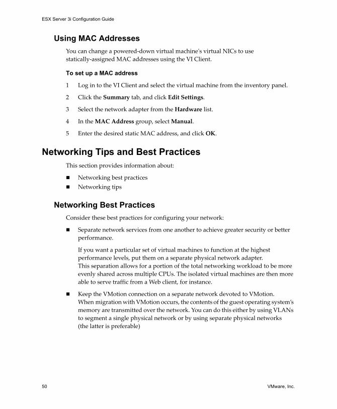
Using MAC AddressesYou can change a powered‐down virtual machineʹs virtual NICs to use statically‐assigned MAC addresses using the VI Client.
To set up a MAC address
1 Log in to the VI Client and select the virtual machine from the inventory panel.
2 Click the Summary tab, and click Edit Settings.
3 Select the network adapter from the Hardware list.
4 In the MAC Address group, select Manual.
5 Enter the desired static MAC address, and click OK.
Networking Tips and Best PracticesThis section provides information about:
Networking best practicesNetworking tips
Networking Best PracticesConsider these best practices for configuring your network:
Separate network services from one another to achieve greater security or better performance.
If you want a particular set of virtual machines to function at the highest performance levels, put them on a separate physical network adapter. This separation allows for a portion of the total networking workload to be more evenly shared across multiple CPUs. The isolated virtual machines are then more able to serve traffic from a Web client, for instance.
Keep the VMotion connection on a separate network devoted to VMotion. When migration with VMotion occurs, the contents of the guest operating system’s memory are transmitted over the network. You can do this either by using VLANs to segment a single physical network or by using separate physical networks (the latter is preferable)

VMware, Inc. 51
Chapter 3 Advanced Networking
Mounting NFS Volumes
In ESX Server 3i, the model of how ESX Server 3i accesses NFS storage of ISO images that are used as virtual CD‐ROMs for virtual machines is different from the model used in ESX Server 2.x.
ESX Server 3i has support for VMkernel‐based NFS mounts. The new model is to mount your NFS volume with the ISO images through the VMkernel NFS functionality. All NFS volumes mounted in this way appear as datastores in the VI Client. The virtual machine configuration editor allows you to browse the ESX Server file system for ISO images to be used as virtual CD‐ROM devices.
Networking TipsConsider the following network hints:
The easiest way to physically separate network services and to dedicate a particular set of network adapters to a specific network service is to create a vSwitch for each service. If this is not possible, they can be separated from each other on a single vSwitch by attaching them to port groups with different VLAN IDs. In either case, confirm with your network administrator that the networks or VLANs you choose are isolated in the rest of your environment, that is, no routers connect them.
You can add and remove network adapters from the vSwitch without affecting the virtual machines or the network service that is running behind that vSwitch. If you removed all the running hardware, the virtual machines would still be able to communicate amongst themselves. Moreover, if you left one network adapter intact, all of the virtual machines would still be able to connect with the physical network.
Use port groups with different sets of active adapters in their teaming policy to separate virtual machines into groups. These can use separate adapters as long as all adapters are up but still fall back to sharing in the event of a network or hardware failure.
Deploy firewalls in virtual machines that route between virtual networks with uplinks to physical networks and pure virtual networks with no uplinks to protect your most sensitive virtual machines.

ESX Server 3i Configuration Guide
52 VMware, Inc.
Networking TroubleshootingThis section guides you through troubleshooting common networking issues.
Troubleshooting Physical Switch ConfigurationIn some cases, you might lose vSwitch connectivity when a failover or failback event occurs. This causes the MAC addresses used by virtual machines associated with that vSwitch to appear on a different switch port than they previously did.
To avoid this problem, put your physical switch in portfast or portfast trunk mode.
Troubleshooting Port Group ConfigurationChanging the name of a port group when virtual machines are already connected to that port group causes the virtual machines configured to connect to that port group to have invalid network configuration.
The connection from virtual network adapters to port groups is made by name, and the name is what is stored in the virtual machine configuration. Changing the name of a port group does not cause a mass reconfiguration of all the virtual machines connected to that port group. Virtual machines that are already powered on will continue to function until they are powered off because their connections to the network have already been established.
The best principle is to avoid renaming networks after they are in use. After you rename a port group, you must re‐configure each associated virtual machine using the Remote CLI to reflect the new port group name.

VMware, Inc. 53
Storage

ESX Server 3i Configuration Guide
54 VMware, Inc.

VMware, Inc. 55
4
The Storage section contains overview information about available storage options for ESX Server 3i and explains how to configure your ESX Server 3i system so it can use and manage different types of storage.
For information on specific activities that a storage administrator might need to perform on a storage side, see the Fibre Channel SAN Configuration Guide and the iSCSI SAN Configuration Guide.
This chapter covers the following topics:
“Storage Overview” on page 56
“Types of Physical Storage” on page 56
“Supported Storage Adapters” on page 59
“Datastores” on page 59
“How Virtual Machines Access Storage” on page 63
“Comparing Types of Storage” on page 64
“Viewing Storage Information in the VMware Infrastructure Client” on page 65
“Configuring and Managing Storage” on page 69
Introduction to Storage 4

ESX Server 3i Configuration Guide
56 VMware, Inc.
Storage OverviewAn ESX Server 3i virtual machine uses a virtual hard disk to store its operating system, program files, and other data associated with its activities. A virtual disk is a large physical file, or a set of files, that can be copied, moved, archived, and backed up as easily as any other file. To store virtual disk files and be able to manipulate the files, ESX Server 3i requires specialized dedicated storage space.
ESX Server 3i uses storage space on a variety of physical storage devices, including your host’s internal and external storage devices, or networked storage devices. The storage device is a physical disk or disk array dedicated to the specific tasks of storing and protecting data.
ESX Server 3i can discover storage devices it has access to and format them as datastores. The datastore is a special logical container, analogous to a file system on a logical volume, where ESX Server 3i places virtual disk files and other files that encapsulate essential components of a virtual machine. Deployed on different devices, the datastores hide specifics of each storage product and provide a uniform model for storing virtual machine files.
Using the VI Client, you can set up datastores in advance on any storage device that your ESX Server 3i discovers.
To learn how to access and configure your storage devices, as well as how to create and manage datastores, see the following chapters:
“Configuring Storage” on page 71
“Managing Storage” on page 99
After you create the datastores, you can use them to store virtual machine files. For information on creating virtual machines, see Basic System Administration.
Types of Physical StorageESX Server 3i storage management process starts with a storage space that your storage administrator preallocates on different storage devices.
ESX Server 3i supports the following types of storage devices:
Local – Stores virtual machine files on internal or external storage devices or arrays attached to your ESX Server 3i host through a direct connection.
Networked – Stores virtual machine files on external shared storage devices or arrays located outside of your ESX Server 3i host. The host communicates with the networked devices through a high‐speed network.

VMware, Inc. 57
Chapter 4 Introduction to Storage
Local StorageLocal storage devices can be internal hard disks located inside your ESX Server 3i host, or external storage systems, located outside and connected to the host directly.
Local storage devices do not require a storage network to communicate with your ESX Server 3i. All you need is a cable connected to the storage device and, when required, a compatible HBA in your ESX Server 3i host.
Generally, you can connect multiple ESX Server 3i hosts to a single local storage system. The actual number of hosts you connect varies depending on the type of storage device and topology you use.
Many storage systems support redundant connection paths to ensure fault tolerance. For more information on multipathing, see “Managing Multiple Paths” on page 103.
When multiple ESX Server 3i hosts connect to the local storage unit, they access storage LUNs in the unshared mode. The unshared mode does not permit several ESX Server 3i hosts to access the same VMFS datastore concurrently. However, a few SAS storage systems offer shared access to multiple ESX Server 3i hosts. This type of access permits multiple ESX Server 3i hosts to access the same VMFS datastore on a LUN. See “Sharing a VMFS Volume Across ESX Server 3i Systems” on page 62.
ESX Server 3i supports a variety of internal or external local storage devices, including SCSI, IDE, SATA, and SAS storage systems. No matter which type of storage you use, ESX Server 3i hides a physical storage layer from virtual machines.
When setting up your local storage, keep in mind the following:
You cannot use IDE/ATA drives to store virtual machines.
Use local SATA storage, both internal and external, in unshared mode only. SATA storage does not support sharing the same LUNs and, therefore, the same VMFS datastore across multiple ESX Server 3i hosts.
When using SATA storage, ensure that your SATA drives are connected through supported dual SATA/SAS controllers.
Some SAS storage systems can offer shared access to the same LUNs (and, therefore, the same VMFS datastores) to multiple ESX Server 3i hosts. For information, see Storage/SAN Compatibility Guide for ESX Server 3.x at www.vmware.com/support/pubs/vi_pubs.html.
For information on supported local storage devices, see I/O Compatibility Guide at www.vmware.com/support/pubs/vi_pubs.html.

ESX Server 3i Configuration Guide
58 VMware, Inc.
Networked StorageNetworked storage devices are external storage devices, or arrays, that your ESX Server 3i uses to store virtual machine files remotely. The ESX Server 3i host accesses these devices over a high‐speed network.
ESX Server 3i supports the following networked storage technologies:
Fibre Channel (FC) SAN – Stores virtual machine files remotely on an FC Storage Area Network (SAN). FC SAN is a specialized high‐speed network that connects your ESX Server 3i hosts to high performance storage devices. The network uses Fibre Channel protocol to transport SCSI traffic from virtual machines to the FC SAN devices.
To connect to the FC SAN, your ESX Server 3i host should be equipped with Fibre Channel host bus adapters (HBAs). In addition, your host requires Fibre Channel switches that help route storage traffic.
Internet SCSI (iSCSI) SAN – Stores virtual machine files on remote iSCSI storage devices. iSCSI packages SCSI storage traffic into the TCP/IP protocol so it can travel through standard TCP/IP networks instead of the specialized FC network. With iSCSI connection, your ESX Server 3i host serves as initiator that communicates with a target, located in remote iSCSI storage systems.
ESX Server 3i offers the following types of iSCSI connection:
Hardware Initiated iSCSI – Your ESX Server 3i host connects to storage through a special third‐party HBA with the iSCSI over TCP/IP capability.
Software Initiated iSCSI – Your ESX Server 3i uses a software‐based iSCSI code in the VMkernel to connect to storage. With this type of iSCSI connection, your host needs only a standard network adapter for network connectivity.
Network‐Attached Storage (NAS) – Stores virtual machine files on remote file servers accessed over standard TCP/IP network. The NFS client built into ESX Server 3i uses the network file system (NFS) protocol version 3 to communicate with the NAS/NFS servers. For network connectivity, the ESX Server 3i host requires a standard network adapter.
For more information on supported networked storage devices, see Storage/SAN Compatibility Guide at www.vmware.com/pdf/vi3_san_guide.pdf.

VMware, Inc. 59
Chapter 4 Introduction to Storage
Supported Storage AdaptersDepending on the type of storage available to you, your ESX Server 3i system might need adapters that provide connectivity to a specific storage device or network. ESX Server 3i supports different classes of adapters, including SCSI, iSCSI, RAID, Fibre Channel, and Ethernet. ESX Server 3i accesses the adapters directly through device drivers in the VMkernel.
For details on the types of adapters ESX Server 3i supports, see I/O Compatibility Guide at www.vmware.com/support/pubs/vi_pubs.html.
DatastoresYou use the VI Client to access different types of storage devices your ESX Server 3i host discovers and to deploy datastores on them. Datastores are special logical containers, analogous to file systems, that hide specifics of each storage device and provide a uniform model for storing virtual machine files.
Datastores can be also used for storing ISO images, virtual machine templates, and floppy images. For more information, see Basic System Administration at www.vmware.com/support/pubs/.
Depending on the type of storage you use, ESX Server 3i datastores can have the following file system formats:
VMFS (VMware File System) – Special high‐performance file system optimized for storing ESX Server 3i virtual machines. ESX Server 3i can deploy VMFS on any SCSI‐based local or networked storage device, including Fibre Channel and iSCSI SAN equipment.
As an alternative to using the VMFS datastore, your virtual machine can have direct access to raw devices using a mapping file (RDM) as a proxy. For more information on RDMs, see “Raw Device Mapping” on page 111.
NFS (Network File System) – File system on a NAS storage device. ESX Server 3i supports NFS version 3 over TCP/IP. ESX Server 3i can access a designated NFS volume located on an NFS server. ESX Server 3i mounts the NFS volume and uses it for its storage needs.

ESX Server 3i Configuration Guide
60 VMware, Inc.
VMFS DatastoresWhen your ESX Server 3i host accesses SCSI‐based storage devices such as SCSI, iSCSI, or FC SAN, the storage space is presented to your ESX Server 3i as a LUN. A LUN is a logical volume that represents storage space on a single physical disk or on a number of disks aggregated in a disk array. A single LUN can be created from the entire space on the storage disk or array, or from a part of the space, called partition. The LUN that uses disk space on more than one physical disk or partition still presents itself as a single logical volume to your ESX Server 3i.
ESX Server 3i can format LUNs as VMFS datastores. VMFS datastores primarily serve as repositories for virtual machines. You can store multiple virtual machines on the same VMFS volume. Each virtual machine, encapsulated in a set of files, occupies a separate single directory. For the operating system inside the virtual machine, VMFS preserves the internal file system semantics, which ensures correct application behavior and data integrity for applications running in virtual machines.
In addition, you can use the VMFS datastores to store other files, such as virtual machine templates and ISO images.
VMFS supports the following file and block sizes enabling your virtual machines to run even the most data intensive applications, including databases, ERP, and CRM in virtual machines:
Maximum virtual disk size: 2TBMaximum file size: 2TB Block size: 1MB to 8MB
Creating and Growing VMFS Datastores
You use the VI Client to set up a VMFS datastore in advance on any SCSI‐based storage device that your ESX Server 3i discovers. ESX Server 3i lets you have up to 256 VMFS datastores per system with the minimum volume size 1.2GB.
For information on creating VMFS datastores on the SCSI‐based storage devices, see the following sections:
“Adding Local Storage” on page 72
“Adding Fibre Channel Storage” on page 75
“Adding iSCSI Storage Accessible Through Hardware Initiators” on page 86
“Adding iSCSI Storage Accessible Through Software Initiators” on page 91
NOTE You should always have only one VMFS datastore per LUN.

VMware, Inc. 61
Chapter 4 Introduction to Storage
After you create the VMFS datastore, you can edit its properties. For more information, see “Editing VMFS Datastores” on page 101.
If your VMFS datastore requires more space, you can dynamically increase the VMFS volume, up to 64TB, by adding an extent. Extent is a LUN on a physical storage device that can be dynamically added to any existing VMFS datastore. The datastore can stretch over multiple extents, yet appear as a single volume.
Considerations when Creating VMFS Datastores
You need to plan how to set up storage for your ESX Server 3i systems before you format storage devices with a VMFS datastore.
You might want fewer, larger VMFS volumes for the following reasons:
More flexibility to create virtual machines without going back to the storage administrator for more space.
More flexibility for resizing virtual disks, doing snapshots, and so on.
Fewer VMFS datastores to manage.
You might want more, smaller VMFS volumes for the following reasons:
Less contention on each VMFS datastore due to locking and SCSI reservation issues.
Less wasted storage space.
Different applications might need different RAID characteristics.
More flexibility, as the multipathing policy and disk shares are set per LUN.
Use of Microsoft Cluster Service requires that each cluster disk resource is in its own LUN.
You might decide to configure some of your servers to use fewer, larger VMFS volumes and other servers to use more, smaller VMFS volumes.
NOTE You cannot reformat a VMFS volume that is in use by a remote ESX Server 3i host. If you attempt to do so, you receive a warning to this effect that specifies the name of the volume in use and the MAC address of a host NIC that is using it. This warning also appears in the VMkernel and VMkwarning log files.

ESX Server 3i Configuration Guide
62 VMware, Inc.
Sharing a VMFS Volume Across ESX Server 3i Systems
As a cluster file system, VMFS lets multiple ESX Server 3i hosts access the same VMFS datastore concurrently. You can connect up to 32 hosts to a single VMFS volume.
Figure 4-1. Sharing a VMFS Volume Across ESX Server 3i Hosts
To ensure that the same virtual machine is not accessed by multiple servers at the same time, VMFS provides on‐disk locking.
Sharing the same VMFS volume across multiple ESX Server 3i hosts gives you the following advantages:
You can use VMware DRS and VMware HA.
You can distribute virtual machines across different physical servers. That means you run a mix of virtual machines on each given server so that not all experience high demand in the same area at the same time.
If a server fails, you can restart virtual machines on another physical server. In case of a failure, the on‐disk lock for each virtual machine is released.
For more information on VMware DRS and VMware HA, see Resource Management Guide at www.vmware.com/support/pubs/.
VMFS volume
ESXServer A
ESXServer B
ESXServer C
virtualdiskfiles
VM1 VM2 VM3
disk1
disk2
disk3

VMware, Inc. 63
Chapter 4 Introduction to Storage
You can perform live migration of running virtual machines from one physical server to another using VMotion.
For more information on VMotion, see Basic System Administration at www.vmware.com/support/pubs/.
You can use VMware Consolidated Backup, which lets a proxy server, called VCB proxy, back up a snapshot of a virtual machine while the virtual machine is powered‐on and is reading and writing to its storage.
For more information on Consolidated Backup, see Virtual Machine Backup Guide at www.vmware.com/support/pubs/.
NFS DatastoreESX Server 3i can access a designated NFS volume located on a NAS server, mount this volume, and use it for its storage needs. You can use NFS volumes to store and boot virtual machines in the same way you use VMFS datastores.
ESX Server 3i supports the following shared storage capabilities on NFS volumes:
Use VMotion.
Use VMware DRS and VMware HA.
Mount ISO images, which are presented as CD‐ROMs to virtual machines.
Create virtual machine snapshots. For more information on snapshots, see Basic System Administration at www.vmware.com/support/pubs/.
How Virtual Machines Access StorageWhen a virtual machine communicates with its virtual disk stored on a datastore, it issues SCSI commands. Because datastores can exist on various types of physical storage, these commands are encapsulated into other forms depending on the protocol the ESX Server 3i host uses to connect to a storage device. ESX Server 3i supports Fibre Channel (FC), Internet SCSI (iSCSI), and NFS protocols.
No matter which type of storage device your ESX Server 3i uses, the virtual disk always appears to the virtual machine as a mounted SCSI device. The virtual disk hides a physical storage layer from the virtual machine’s operating system. This allows you to run even operating systems not certified for specific storage equipment, such as SAN, inside the virtual machine.
The diagram in Figure 4‐2 depicts five virtual machines using different types of storage to illustrate the differences between each type.

ESX Server 3i Configuration Guide
64 VMware, Inc.
Figure 4-2. Virtual machines accessing different types of storage
Comparing Types of StorageTable 4‐1 compares different networked storage technologies supported by ESX Server 3i.
NOTE This diagram is for conceptual purposes only. It is not a recommended configuration.
iSCSI array NAS appliancefibre array
ESX Server
VMFS
localethernet
SCSI
VMFS VMFS NFS
virtualmachine
virtualmachine
virtualmachine
virtualmachine
virtualmachine
SAN LAN LAN LAN
iSCSI hardwareinitiator
fibrechannelHBA
ethernetNIC
ethernetNIC
software initiator
requires TCP/IP connectivity
Key
physicaldisk
datastore
virtualdisk
Table 4-1. Networked Storage Supported by ESX Server 3i
Technology Protocols Transfers Interface
Fibre Channel FC/SCSI Block access of data/LUN
FC HBA
iSCSI IP/SCSI Block access of data/LUN
iSCSI HBA (hardware‐initiated iSCSI)NIC (software‐initiated iSCSI)
NAS IP/NFS File (no direct LUN access)
NIC

VMware, Inc. 65
Chapter 4 Introduction to Storage
Table 4‐2 compares the ESX Server 3i features supported by different types of storage.
Viewing Storage Information in the VMware Infrastructure Client
The VI Client displays detailed information on available datastores, storage devices the datastores use, and configured adapters.
Displaying DatastoresDatastores are added to the VI Client in one of the following ways:
Created by default on the ESX Server 3i host first boot – When you first power on the ESX Server 3i host, the software formats any visible blank local disks or partitions with VMFS datastores so that you can create virtual machines on the datastores.
You can override this default behavior if, for example, your policy is to use shared storage devices instead of local storage. To prevent automatic disk formatting, detach local storage devices from the host before you power on the host for the first time. If automatic disk formatting already occurred and you want to override the VMFS formatting, remove the datastore.
Discovered when a host is added to the inventory – When you add a new host to the inventory, the VI Client displays any datastores that have been created on the host.
Created on an available storage device – You can use the Add Storage option to create and configure a new datastore. For more information, see “Configuring Storage” on page 71.
You can view a list of available datastores and analyze their properties.
Table 4-2. ESX Server 3i Features Supported by Storage
Storage TypeBoot VM VMotion Datastore RDM
VM Cluster
VMware HA and DRS VCB
SCSI Yes No VMFS No No No Yes1
Fibre Channel Yes Yes VMFS Yes Yes Yes Yes
iSCSI Yes Yes VMFS Yes No Yes Yes
NAS over NFS Yes Yes NFS No No Yes Yes1
1. Does not offer offloading capabilities of VCB run over Fibre Channel or iSCSI SAN.

ESX Server 3i Configuration Guide
66 VMware, Inc.
To display datastores, on the host Configuration tab, click the Storage link.
For each datastore, the Storage section shows summary information, including:
Target storage device where the datastore is located. See “Understanding Storage Device Naming in the Display” on page 67.
Type of file system the datastore uses. See “Datastores” on page 59.
Total formatted capacity of the datastore, and available space.
To view additional details about the specific datastore, select the datastore from the list.
The Details section shows the following information:
Location of the datastore.
Individual extents the datastore spans and their capacity (VMFS datastores).
Paths used to access the storage device (VMFS datastores).
In Figure 4‐3, the symm_07 datastore is selected from the list of available datastores. The Details pane provides information about the path policy, the number of paths, and available extents.
Figure 4-3. Datastore information
To view more details for each extent, click Properties and select in the Extents panel.
configured datastores datastore details

VMware, Inc. 67
Chapter 4 Introduction to Storage
You can refresh and remove any of the existing datastores, and change properties of a VMFS datastore. When you edit a VMFS datastore, you can change its label, add extents, upgrade it, or modify paths for storage devices. For more information, see “Managing Storage” on page 99.
Understanding Storage Device Naming in the DisplayIn the VI Client, the name of a storage device presented to your ESX Server 3i host is displayed as a sequence of three numbers, separated by colons, such as vmhba0:0:49. The name has the following meaning:
<HBA>:<SCSI target>:<SCSI LUN>
The abbreviation vmhba refers to different physical HBAs on the ESX Server 3i system. It can also refer to the software iSCSI initiator that ESX Server 3i implements using the VMkernel network stack.
The vmhba0:0:49 example means that through HBA0, your ESX Server 3i host can access SCSI target 0 and format LUN49 with VMFS.
After you create a datastore on the storage device, the device name has the following format:
<HBA>:<SCSI target>:<SCSI LUN>:<disk partition>
The forth number indicates a partition on a LUN occupied by a VMFS datastore.
While the third and the forth numbers never change, the first two numbers can change. For example, after rebooting the ESX Server 3i system, vmhba1:1:3:1 can change to vmhba3:2:3:1, however, the name still refers to the same physical device. The first and the second numbers can change for the following reasons:
The first number, the HBA, changes when an outage on the Fibre Channel or iSCSI network occurs. In this case, the ESX Server 3i system has to use a different HBA to access the storage device.
The second number, the SCSI target, changes in case of any modifications in the mappings of the Fibre Channel or iSCSI targets visible to the ESX Server 3i host.

ESX Server 3i Configuration Guide
68 VMware, Inc.
Viewing Storage AdaptersThe VI Client displays any storage adapters available to your system.
To display storage adapters, on the host Configuration tab, click the Storage Adapters link.
You can view the following information about the storage adapters:
Existing storage adapters.
Type of storage adapter, such as Fibre Channel SCSI or iSCSI.
Details for each adapter, such as the storage device it connects to and target ID.
To view configuration properties for a specific adapter, select the adapter from the Storage Adapters list.
In Figure 4‐4, the iSCSI storage adapter “vmhba0” is selected. The Details view provides information about the number of LUNs the adapter connects to and the paths is uses.
If you want to change the path’s configuration, you can select this path from the list, right‐click the path, and click Manage Paths to bring up the Manage Paths dialog box. For information on managing paths, see “Managing Multiple Paths” on page 103.
Figure 4-4. Storage Adapter Information

VMware, Inc. 69
Chapter 4 Introduction to Storage
Configuring and Managing StorageThe Configuring Storage and Managing Storage chapters of this guide cover most of the concepts and outline tasks you need to perform when working with storage.
For detailed information on configuring SANs, see the Fibre Channel SAN Configuration Guide SAN and iSCSI SAN Configuration Guide.
Follow these links to read more on specific storage configuration tasks:
Local Storage Configuration Task:
“To create a datastore on a local SCSI disk” on page 73
Fibre Channel SAN Storage Configuration Task:
“To create a datastore on a Fibre Channel device” on page 75
Hardware‐Initiated iSCSI Storage Configuration Tasks:
“To view the hardware iSCSI initiator properties” on page 80
“To set up the iSCSI name, alias, and IP address for the hardware initiator” on page 82
“To set up target discovery addresses using dynamic discovery” on page 83
“To set up CHAP parameters for the hardware initiator” on page 85
“To create a datastore on a hardware iSCSI device” on page 86
Software‐Initiated iSCSI Storage Configuration Tasks:
“To view the software iSCSI initiator properties” on page 88
“To enable the software iSCSI initiator” on page 90
“To set up target discovery addresses for the software initiator” on page 90
“To set up CHAP parameters for the software initiator” on page 90
“To create a datastore on an iSCSI device accessed through software initiators” on page 91
NAS Storage Configuration Task:
“To mount an NFS volume” on page 95

ESX Server 3i Configuration Guide
70 VMware, Inc.
Storage Management Tasks
“To upgrade the VMFS‐2 to VMFS‐3” on page 102
“To edit the name of the datastore” on page 102
“To add one or more extents to the datastore” on page 103
“To remove a datastore” on page 100
Path Managing Tasks
“To set the multipathing policy” on page 109
“To disable a path” on page 110
“To set the preferred path (for Fixed multipathing policy)” on page 110

VMware, Inc. 71
5
This chapter contains information about configuring local storage devices, Fibre Channel SAN storage, iSCSI storage, and NAS storage.
This chapter covers the following topics:
“Local Storage” on page 72
“Fibre Channel Storage” on page 74
“iSCSI Storage” on page 76
“Performing a Rescan” on page 92
“Network Attached Storage” on page 93
“Creating a Diagnostic Partition” on page 95
Configuring Storage 5NOTE For additional information about configuring SANs, see the Fibre Channel SAN Configuration Guide and iSCSI SAN Configuration Guide.

ESX Server 3i Configuration Guide
72 VMware, Inc.
Local StorageThe local storage uses a SCSI‐based device such as your ESX Server 3i host’s hard disk or any external dedicated storage system connected directly to your ESX Server 3i host. These external storage systems are called direct attached storage (DAS).
Figure 5‐1 depicts a virtual machine using local storage.
Figure 5-1. Local SCSI-Based Storage
In this example of local storage topology, your ESX Server 3i host uses a single connection to plug into a storage disk. On that disk, you can create a VMFS datastore, which you use to store virtual machine disk files.
Although this storage configuration is possible, it is not a recommended topology. Using single connections between storage arrays and ESX Server 3i hosts creates single points of failure (SPOF) that can cause interruptions when a connection becomes unreliable or fails. To ensure fault tolerance, many local storage systems support redundant connection paths. For more information on using multiple paths with ESX Server 3i, see “Managing Multiple Paths” on page 103.
Adding Local StorageAs soon as you load storage adapter drivers, ESX Server 3i detects available SCSI storage devices. Before creating a new datastore on a SCSI device, you might need to perform a rescan. See “Performing a Rescan” on page 92.
When you create a datastore on a SCSI storage device, the Add Storage wizard guides you through the configuration steps.
ESX Server
VMFS
localethernet
SCSI
virtualmachine

VMware, Inc. 73
Chapter 5 Configuring Storage
To create a datastore on a local SCSI disk
1 Log in to the VI Client and select the server from the inventory panel.
2 Click the Configuration tab and click Storage in the Hardware panel.
3 Click Add Storage.
4 Select the Disk/LUN storage type and click Next.
5 Select the SCSI device to use for your datastore and click Next.
The Current Disk Layout page opens. If the disk you are formatting is blank, the entire disk space is automatically presented to you for storage configuration.
6 If the disk is not blank, review the current disk layout in the top panel of the Current Disk Layout page and select a configuration option from the bottom panel:
Use the entire device — Select this option to dedicate the entire disk or LUN to a single VMFS datastore. VMware recommends that you select this option.
Use free space — Select this option to deploy a VMFS datastore in the remaining free space of the disk.
7 Click Next.
8 In the Disk/LUN–Properties page, enter a datastore name and click Next.
The Disk/LUN–Formatting page appears.
9 If needed, adjust the file system and capacity values.
By default, the entire free space available on the storage device is offered to you.
10 Click Next.
The Ready to Complete page appears.
11 In the Ready to Complete page, review the datastore configuration information and click Finish.
This process creates a datastore on the local SCSI‐based disk on your ESX Server 3i host.
WARNING If you select this option, any file systems or data previously stored on this device will be destroyed.

ESX Server 3i Configuration Guide
74 VMware, Inc.
Fibre Channel StorageESX Server 3i supports Fibre Channel adapters, which allow an ESX Server 3i system to be connected to a SAN and to see the disk arrays on the SAN.
Figure 5‐2 depicts virtual machines using Fibre Channel storage.
Figure 5-2. Fibre Channel Storage
In this configuration, an ESX Server 3i system connects to a SAN fabric, which consists of Fibre Channel switches and storage arrays, using a Fibre Channel adapter. LUNs from the storage array become available to your ESX Server 3i system. You can access the LUNs and create a datastore that you use for your storage needs. The datastore uses the VMFS format.
fibre array
VMFS
virtualmachine
SAN
fibrechannelHBA
ESX Server

VMware, Inc. 75
Chapter 5 Configuring Storage
For additional information:
About configuring SANs, see the Fibre Channel SAN Configuration Guide.
About supported SAN storage devices for ESX Server 3i, see the SAN Compatibility Guide.
About multipathing for Fibre Channel HBAs and how to manage paths, see “Managing Multiple Paths” on page 103.
Adding Fibre Channel StorageBefore creating a new datastore on a Fibre Channel device, rescan a Fibre Channel adapter to discover any newly added LUNs. See “Performing a Rescan” on page 92.
When you create a datastore on a Fibre Channel storage device, the Add Storage wizard guides you through the configuration.
To create a datastore on a Fibre Channel device
1 Log in to the VI Client, and select a server from the inventory panel.
2 Click the Configuration tab and click Storage in the Hardware panel.
3 Click Add Storage.
4 Select the Disk/LUN storage type and click Next.
5 Select the Fibre Channel device to use for your datastore and click Next.
The Current Disk Layout page opens. If the disk you are formatting is blank, the entire disk space is automatically presented to you for storage configuration.
6 If the disk is not blank, review the current disk layout in the top panel of the Current Disk Layout page and select a configuration option from the bottom panel:
Use the entire device — Select this option to dedicate the entire disk or LUN to a single VMFS datastore. VMware recommends that you select this option.
Use free space — Select this option to deploy a VMFS datastore in the remaining free space of the disk.
7 Click Next.
8 In the Disk/LUN–Properties page, enter a datastore name and click Next.
The Disk/LUN–Formatting page appears.
WARNING If you select this option, any file systems or data previously stored on this device will be destroyed.

ESX Server 3i Configuration Guide
76 VMware, Inc.
9 If needed, adjust the file system and capacity values.
By default, the entire free space available on the storage device is offered to you.
10 Click Next.
11 In the Ready to Complete page, review the datastore configuration information and click Finish.
This process creates the datastore on a Fibre Channel disk for the ESX Server 3i host.
12 Click Refresh.
For advanced configuration, such as using multipathing, masking, and zoning, see the Fibre Channel SAN Configuration Guide.
iSCSI StorageESX Server 3i supports iSCSI technology that allows your ESX Server 3i system to use an IP network while accessing remote storage. With iSCSI, SCSI storage commands that your virtual machine issues to its virtual disk are converted into TCP/IP protocol packets and transmitted to a remote device, or target, that stores the virtual disk. From the point of view of the virtual machine, the device appears as a locally attached SCSI drive.
iSCSI InitiatorsTo access remote targets, your ESX Server 3i host uses iSCSI initiators. Initiators transport SCSI requests and responses between the ESX Server 3i system and the target storage device on the IP network.
ESX Server 3i supports hardware‐based and software‐based iSCSI initiators:
Hardware iSCSI initiator – A third‐party host bus adapter (HBA) with the iSCSI over TCP/IP capability. This specialized iSCSI adapter is responsible for all iSCSI processing and management.
Software iSCSI initiator – A code built into VMkernel that lets your ESX Server 3i system to connect to the iSCSI storage device through standard network adapters. The software initiator handles the iSCSI processing while communicating with the network adapter through the network stack. With the software initiator, you can use the iSCSI technology without purchasing specialized hardware.

VMware, Inc. 77
Chapter 5 Configuring Storage
Figure 5‐3 depicts two virtual machines that use different types of iSCSI initiators.
Figure 5-3. iSCSI Storage
In the first example of iSCSI storage configuration, the ESX Server 3i system uses the hardware iSCSI adapter. This specialized iSCSI adapter sends iSCSI packets to a disk over a LAN.
In the second example, the ESX Server 3i system is configured with the software iSCSI initiator. Using the software initiator, the ESX Server 3i system connects to a LAN through an existing NIC card.
NOTE Guest operating systems in virtual machines cannot see iSCSI storage directly. To the guest operating systems, iSCSI storage attached to the ESX Server 3i system appears to be available through a SCSI HBA.
iSCSI array
VMFS
virtualmachine
virtualmachine
LAN LAN
iSCSI hardwareinitiator
ethernetNIC
software initiator
ESX Server

ESX Server 3i Configuration Guide
78 VMware, Inc.
Naming RequirementsAll iSCSI initiators and targets that use the iSCSI network have unique and permanent iSCSI names and are assigned addresses for access. The iSCSI name provides identification of a particular iSCSI device, an initiator or a target, regardless of its physical location.
When configuring your iSCSI initiators, make sure they have properly formatted names. The initiators can use one of the following formats:
IQN (iSCSI qualified name) – Can be up to 255 characters long and has the following format:
iqn.<year-mo>.<reversed_domain_name>:<unique_name>
where <year-mo> represents the year and month your domain name was registered, <reversed_domain_name> is the official domain name, reversed, and <unique_name> is any name you want to use, for example, the name of your server.
An example might be iqn.1998-01.com.mycompany:myserver.
EUI (extended unique identifier) – Represents the eui. prefix followed by the 16‐character name. The name includes 24 bits for company name assigned by the IEEE and 40 bits for a unique ID such as a serial number.
For example, eui.0123456789ABCDEF.
Discovery MethodsTo determine which storage resource on the network is available for access, the ESX Server 3i system uses these discovery methods:
Dynamic Discovery – With this method, also known as Send Targets discovery, each time the initiator contacts a specified iSCSI server, it sends the Send Targets request to the server. The server responds by providing a list of available targets to the initiator.
Static Discovery – With this method, the initiator does not need to perform any discovery. The initiator in advance knows all targets it will be contacting and uses their IP addresses and domain names to communicate with them.
The static discovery method is available only when the iSCSI storage is accessed through hardware initiators.

VMware, Inc. 79
Chapter 5 Configuring Storage
iSCSI SecurityBecause iSCSI technology uses the IP networks to connect to remote targets, it is necessary to ensure security of the connection. The IP protocol itself doesn’t protect the data it transports, and it doesn’t have the capability to verify the legitimacy of initiators that access targets on the network. You need to take specific measures to guarantee security across IP networks.
ESX Server 3i supports the Challenge Handshake Authentication Protocol (CHAP) that your iSCSI initiators can use for authentication purposes. After your initiator establishes the initial connection with the target, CHAP verifies the identity of the initiator and checks a CHAP secret that your initiator and the target share. This can be repeated periodically during the iSCSI session.
When configuring iSCSI initiators for your ESX Server 3i system, check whether the iSCSI storage supports CHAP and if it does, make sure to enable it for your initiators.
See “Securing iSCSI Storage” on page 157.
Configuring Hardware iSCSI Initiators and StorageWhen your ESX Server 3i host access the iSCSI storage through hardware initiators, it uses a specialized third‐party adapter capable of accessing iSCSI storage over TCP/IP. This iSCSI adapter handles all iSCSI processing and management for your ESX Server 3i system.
Install and configure the hardware iSCSI adapter before setting up the datastore that resides on an iSCSI storage device.
Installing and Viewing Hardware iSCSI Initiators
For information on which adapters are supported, see the I/O Compatibility Guide on the VMware Web site at www.vmware.com.
Before you begin configuring the hardware iSCSI initiator, make sure that the iSCSI HBA is successfully installed and appears on the list of adapters available for configuration. If the initiator is installed, you can view its properties.

ESX Server 3i Configuration Guide
80 VMware, Inc.
To view the hardware iSCSI initiator properties
1 Log in to the VI Client, and select a server from the inventory panel.
2 Click the Configuration tab and click Storage Adapters in the Hardware panel.
The hardware iSCSI initiator appears on the list of storage adapters.
3 Select the initiator you to configure.
The details for the initiator appear, including the model, IP address, iSCSI name, discovery methods, iSCSI alias, and any discovered targets.

VMware, Inc. 81
Chapter 5 Configuring Storage
4 Click Properties.
The iSCSI Initiator Properties dialog box opens. The General tab displays additional characteristics of the initiator.
You can now configure your hardware initiator or change its default characteristics.
Configuring Hardware iSCSI Initiators
While configuring the hardware iSCSI initiator, set up your initiator’s iSCSI name, IP address, and discovery addresses. In addition, VMware recommends that you set up CHAP parameters.
After you configure your hardware iSCSI initiator, perform a rescan, so that all LUNs that the initiator can access appear on the list of storage devices. See “Performing a Rescan” on page 92.

ESX Server 3i Configuration Guide
82 VMware, Inc.
Setting up Naming Parameters
When you configure your hardware iSCSI initiators, make sure their names and IP addresses are formatted properly.
See “Naming Requirements” on page 78.
To set up the iSCSI name, alias, and IP address for the hardware initiator
1 In the iSCSI Initiator Properties dialog box, click Configure.
2 To change the default iSCSI name for your initiator, enter the new name.
You can use the default name that the vendor supplied. If you change the default name, make sure the new name you enter is properly formatted. Otherwise, some storage devices may not recognize the hardware iSCSI initiator.
3 Enter the iSCSI alias.
The alias is a name that you use to identify the hardware iSCSI initiator.
4 Enter all the required values in the Hardware Initiator Properties group.
5 Click OK to save your changes.
6 Reboot the server for the changes to take effect.
Setting up Discovery Addresses for Hardware Initiators
Set up target discovery addresses so that the hardware initiator can determine which storage resource on the network is available for access. You can do this with either dynamic discovery or static discovery.
See “Discovery Methods” on page 78
With dynamic discovery, a particular iSCSI server supplies a list of targets to your ESX Server 3i host.

VMware, Inc. 83
Chapter 5 Configuring Storage
To set up target discovery addresses using dynamic discovery
1 In the iSCSI Initiator Properties dialog box, click the Dynamic Discovery tab.
2 To add a new iSCSI server that your ESX Server 3i host can use for a dynamic discovery session, click Add.
3 In the Add Send Targets Server dialog box, enter the IP address of the iSCSI server and click OK.
After your ESX Server 3i host establishes the dynamic discovery session with this server, the server responds by providing a list of targets available to your ESX Server 3i host. The names and IP addresses of these targets appear on the Static Discovery tab.
4 To change the IP address of the iSCSI server or remove the server, select the IP address and click Edit or Remove.

ESX Server 3i Configuration Guide
84 VMware, Inc.
With hardware initiators, in addition to the dynamic discovery method, you can also use static discovery, where you manually enter the IP addresses and the iSCSI names of the targets to be contacted.
To set up target discovery address using static discovery
1 In the iSCSI Initiator Properties dialog box, click the Static Discovery tab.
If you previously used the dynamic discovery method, the tab displays any targets supplied to your ESX Server 3i host by the iSCSI server.
2 To add a target, click Add and enter the target’s IP address and fully qualified name.
3 To change or delete a specific target, select the target and click Edit or Remove.
NOTE If you remove a target added by dynamic discovery, the target might be returned to the list the next time a rescan happens, the HBA is reset, or the system is rebooted.

VMware, Inc. 85
Chapter 5 Configuring Storage
Setting up CHAP Parameters for Hardware Initiators
When you configure your hardware iSCSI initiator, verify whether CHAP is enabled on the iSCSI storage. If it is enabled, you need to enable it for your initiator, making sure that the CHAP authentication credentials match your iSCSI storage.
See “iSCSI Security” on page 79.
To set up CHAP parameters for the hardware initiator
1 In the iSCSI Initiator Properties dialog box, click the CHAP Authentication tab.
The tab displays the default CHAP parameters, if any.
2 To make any changes to the existing CHAP parameters, click Configure.
3 To keep CHAP enabled, select Use the following CHAP credentials.

ESX Server 3i Configuration Guide
86 VMware, Inc.
4 Either enter a new CHAP name, or select Use initiator name.
5 If needed, specify the CHAP secret.
All new targets will use the CHAP secret to authenticate the initiator.
6 Click OK to save changes.
Adding iSCSI Storage Accessible Through Hardware Initiators
When you create a datastore on an iSCSI storage device accessible through a hardware initiator, the Add Storage wizard guides you through the configuration.
To create a datastore on a hardware iSCSI device
1 Log in to the VI Client, and select a server from the inventory panel.
2 Click the Configuration tab and click Storage in the Hardware panel.
3 Click Add Storage.
4 Select the Disk/LUN storage type and click Next.
5 Select the iSCSI device to use for your datastore and click Next.
The Current Disk Layout page opens. If the disk you are formatting is blank, the entire disk space is automatically presented to you for storage configuration.
6 If the disk is not blank, review the current disk layout in the top panel of the Current Disk Layout page and select a configuration option from the bottom panel:
Use the entire device — Select this option to dedicate the entire disk or LUN to a single VMFS datastore. VMware recommends that you select this option.
Use free space — Select this option to deploy a VMFS datastore in the remaining free space of the disk.
7 Click Next.
8 In the Disk/LUN–Properties page, enter a datastore name and click Next.
The Disk/LUN–Formatting page appears.
NOTE If you disable CHAP, existing sessions remain until you reboot your ESX Server 3i host or the storage system forces a logout. After this, you can no longer connect to targets that require CHAP.
WARNING If you select this option, any file systems or data previously stored on this device will be destroyed.

VMware, Inc. 87
Chapter 5 Configuring Storage
9 If needed, adjust the file system and capacity values.
By default, the entire free space available on the storage device is offered to you.
10 Click Next.
11 In the Ready to Complete page, review the datastore configuration information and click Finish.
This creates the datastore on the hardware‐initiated iSCSI device.
12 Click Refresh.
Configuring Software iSCSI Initiators and StorageWith the software‐based iSCSI implementation, you can use a standard network adapter to connect your ESX Server 3i system to a remote iSCSI target on the IP network. The ESX Server 3i software iSCSI initiator built into VMkernel facilitates this connection communicating with the network adapter through the network stack.
Before configuring datastores that use software initiators to access the iSCSI storage, enable network connectivity, and then install and configure the software iSCSI initiator.
Setting Up the iSCSI Storage Accessible Through Software Initiators
Perform the following tasks when you prepare and set up datastores that use software initiators to access the iSCSI storage device:
1 Create a VMkernel port to handle iSCSI networking.
See “VMkernel Networking Configuration” on page 28.
2 Configure the software iSCSI initiator.
See “Configuring Software iSCSI Initiators” on page 89.
3 Rescan for new iSCSI LUNs.
See “Performing a Rescan” on page 92.
4 Set up the datastore.
See “Adding iSCSI Storage Accessible Through Software Initiators” on page 91.
Viewing Software iSCSI Initiators
The software iSCSI adapter that your ESX Server 3i system uses to access an iSCSI storage device appears on the list of available adapters. You can use the VI Client to review its properties.

ESX Server 3i Configuration Guide
88 VMware, Inc.
To view the software iSCSI initiator properties
1 Log in to the VI Client, and select a server from the inventory panel.
2 Click the Configuration tab and click Storage Adapters in the Hardware panel.
The list of available storage adapters appears.
3 Under iSCSI Software Adapter, choose the available software initiator.
If the initiator is enabled, the Details panel displays the initiator’s model, IP address, iSCSI name, discovery methods, iSCSI alias, and any discovered targets.

VMware, Inc. 89
Chapter 5 Configuring Storage
4 Click Properties.
The iSCSI Initiator Properties dialog box opens. The General tab displays additional characteristics of the software initiator.
You can now configure your software initiator or change its default characteristics.
Configuring Software iSCSI Initiators
When you configure the software iSCSI initiator, you enable your initiator and set up its target addresses. VMware also recommends that you set up the CHAP parameters.
After you configure your software iSCSI initiator, perform a rescan, so that all LUNs that the initiator has access to appear on the list of storage devices available to your ESX Server 3i. See “Performing a Rescan” on page 92.

ESX Server 3i Configuration Guide
90 VMware, Inc.
Enabling Software iSCSI Initiators
Enable your software iSCSI initiator, so that ESX Server 3i can use it.
To enable the software iSCSI initiator
1 In the iSCSI Initiator Properties dialog box, click Configure.
2 To enable the initiator, select Enabled.
3 To change the default iSCSI name for your initiator, enter the new name.
Make sure the name you enter is properly formatted. Otherwise, some storage devices might not recognize the initiator. See “Naming Requirements” on page 78.
4 Click OK to save your changes.
Setting up Discovery Addresses for Software Initiators
Set up target discovery addresses so that the software initiator can determine which storage resource on the network is available for access.
See “Discovery Methods” on page 78.
To set up target discovery addresses for the software initiator
1 In the iSCSI Initiator Properties dialog box, click the Dynamic Discovery tab.
2 To add a new iSCSI server your ESX Server 3i host can use for a dynamic discovery session, click Add.
3 Enter the Send Targets server IP address and click OK.
4 To change or delete the Send Targets server, select the server and click Edit or Remove.
Setting up CHAP Parameters for Software Initiators
When you configure your software iSCSI initiator, verify whether CHAP is enabled on the iSCSI storage. If it is enabled, you need to enable it for your initiator, making sure that the CHAP authentication credentials match your iSCSI storage.
See “iSCSI Security” on page 79.
To set up CHAP parameters for the software initiator
1 In the iSCSI Initiator Properties dialog box, click the CHAP Authentication tab.
2 To specify CHAP parameters, click Configure.
NOTE With software initiators, only the dynamic discovery method is available.

VMware, Inc. 91
Chapter 5 Configuring Storage
3 To keep CHAP enabled, select Use the following CHAP credentials.
4 Enter a CHAP name, or select Use initiator name.
5 If needed, specify the CHAP secret.
All new targets will use the CHAP secret to authenticate the initiator.
6 Click OK to save changes.
Adding iSCSI Storage Accessible Through Software Initiators
When you create a datastore on an iSCSI storage device accessible through software initiators, the Add Storage wizard guides you through the configuration.
To create a datastore on an iSCSI device accessed through software initiators
1 Log in to the VI Client, and select a server from the inventory panel.
2 Click the Configuration tab and click Storage in the Hardware panel.
3 Click Add Storage.
4 Select the Disk/LUN storage type and click Next.
5 Select the iSCSI device to use for your datastore and click Next.
The Current Disk Layout page appears. If the disk you are formatting is blank, the entire disk space is automatically presented to you for storage configuration.
6 If the disk is not blank, review the current disk layout in the top panel of the Current Disk Layout page and select a configuration option from the bottom panel:
Use the entire device — Select this option to dedicate the entire disk or LUN to a single VMFS datastore. VMware recommends that you select this option.
Use free space — Select this option to deploy a VMFS datastore in the remaining free space of the disk.
7 Click Next.
8 In the Disk/LUN–Properties page, enter a datastore name and click Next.
NOTE If you disable CHAP, existing sessions remain until you reboot your ESX Server 3i host or the storage system forces a logout. After this, you can no longer connect to targets that require CHAP.
WARNING If you select this option, any file systems or data previously stored on this device will be destroyed.

ESX Server 3i Configuration Guide
92 VMware, Inc.
9 If needed, adjust the file system and capacity values.
By default, the entire free space available on the storage device is offered to you.
10 Click Next.
11 In the Ready to Complete page, review the datastore configuration information and click Finish.
This creates the datastore on the iSCSI storage device accessed through the software initiator.
12 Click Refresh.
Performing a RescanPerform a rescan if any of the following events occur:
When you make changes to storage disks or LUNs available to your ESX Server 3i system.
When you make changes to storage adapters
When you create a new datastore or remove an existing one.
When you reconfigure an existing datastores, for example, when you add a new extent.
To perform a rescan
1 In the VI Client, select a host and click the Configuration tab.
2 Choose Storage Adapters in the Hardware panel and click Rescan above the Storage Adapters panel.
3 To discover new disks or LUNs, select Scan for New Storage Devices.
If new LUNs are discovered, they appear in the disk/LUN list.
4 To discover new datastores or update a datastore after its configuration has been changed, select Scan for New VMFS Volumes.
If new datastores are discovered, they appear in the datastore list.
NOTE After you mask all paths to a LUN, rescan all adapters with paths to the LUN in order to update the configuration.
NOTE You can also right‐click an individual adapter and click Rescan to rescan just that adapter.

VMware, Inc. 93
Chapter 5 Configuring Storage
Network Attached StorageThis section contains information about network attached storage (NAS).
ESX Server 3i supports using NAS through the NFS protocol.
How Virtual Machines Use NFSThe NFS protocol that ESX Server 3i supports enables communication between an NFS client and NFS server. The client issues requests for information from the server, which replies with the result.
The NFS client built into ESX Server 3i lets you access the NFS server and use NFS volumes to store virtual machine disks. ESX Server 3i supports NFS Version 3 over TCP only.
You use the VI Client to configure NFS volumes as datastores. Configured NFS datastores appear in the VI Client and you can use them to store virtual disk files in the same way you use VMFS‐based datastores.
The virtual disks that you create on NFS‐based datastores use a disk format dictated by the NFS server, typically a thin disk format that requires on‐demand space allocation. If the virtual machine runs out of space while writing to this disk, the VI Client notifies you that more space is needed. You have the following options:
Free up additional space on the volume, so that the virtual machine continues writing to the disk.
Terminate the virtual machine session. Terminating the session, shuts down the virtual machine.
Figure 5‐4 depicts a virtual machine using the NFS volume to store its files.

ESX Server 3i Configuration Guide
94 VMware, Inc.
Figure 5-4. NFS Storage
In this configuration, ESX Server 3i connects to the NFS server, which stores the virtual disk files.
NFS Volumes and Virtual Machine Delegate UsersIf you are planning to create, configure, or administer virtual machines on an NFS‐based datastore, assign NFS access privileges to a special user, known as the delegate user.
By default, the delegate user for the ESX Server 3i host is root. However, having root as the delegate user may not work for all NFS volumes. In some cases, to protect NFS volumes from unauthorized access, NFS administrators may export the volumes with the root squash option turned on. When root squash is on, the NFS server treats access by root as access by any unprivileged user and might refuse the ESX Server 3i host access to virtual machine files stored on the NFS volume.
NAS appliance
NFS
virtualmachine
LAN
ethernetNIC
ESX Server
WARNING When ESX Server 3i accesses a virtual machine disk file on an NFS‐based datastore, a special .lck-XXX lock file is generated in the same directory where the disk file resides to prevent other ESX Server 3i hosts from accessing this virtual disk file. Do not remove the .lck-XXX lock file, otherwise the running virtual machine will not be able to access its virtual disk file.

VMware, Inc. 95
Chapter 5 Configuring Storage
You can change the delegate user to a different identity through experimental ESX Server 3i functionality. This identity must match the owner of the directory on the NFS server, otherwise the ESX Server 3i host cannot perform file level operations.
See “Virtual Machine Delegates for NFS Storage” on page 183.
Configuring ESX Server 3i to Access NFS VolumesNFS requires network connectivity to access data stored on remote servers. Before configuring NFS, you must first configure networking for VMotion and IP storage.
For information on configuring a network, see “VMkernel Networking Configuration” on page 28.
Creating an NFS-Based DatastoreWhen you create a datastore on an NFS volume, the Add Storage wizard guides you through the configuration steps.
To mount an NFS volume
1 Log in to the VI Client, and select a server from the inventory panel.
2 Click the Configuration tab and click Storage in the Hardware panel.
3 Click Add Storage.
4 Select Network File System as the storage type and click Next.
5 Enter the server name, the mount point folder, and the datastore name.
6 Click Next.
7 In the Network File System Summary page, review the configuration options and click Finish.
Creating a Diagnostic PartitionTo be able to run your ESX Server 3i, you need to configure a diagnostic partition, or a dump partition, used to store core dumps for debugging and technical support. You can create the diagnostic partition on a local disk, or on a private or shared SAN LUN.
A diagnostic partition cannot be located on an iSCSI LUN accessed through a software initiator.
WARNING Changing the delegate user for an ESX Server 3i host is experimental and, currently, VMware provides limited support for this feature.

ESX Server 3i Configuration Guide
96 VMware, Inc.
Each ESX Server 3i host must have the diagnostic partition of 100MB. If multiple ESX Server 3i hosts share a SAN, configure a diagnostic partition with 100MB for each host.
To create a diagnostic partition
1 Log in to the VI Client, and select a server from the inventory panel.
2 Click the Configuration tab and click Storage in the Hardware panel.
3 Click Add Storage.
The Select Storage Type page appears.
4 Select Diagnostic and click Next.
If you do not see Diagnostic as an option, ESX Server 3i host already has a diagnostic partition. You can query and scan your host’s diagnostic partition using the vicfg-dumppart command in the command‐line interface. See the Remote Command‐Line Interface Installation and Reference Guide.

VMware, Inc. 97
Chapter 5 Configuring Storage
5 Specify the type of the diagnostic partition:
Private Local – Creates the diagnostic partition on a local disk. This partition stores fault information only for your ESX Server 3i host.
Private SAN Storage – Creates the diagnostic partition on a non‐shared SAN LUN. This partition stores fault information only for your ESX Server 3i host.
Shared SAN Storage – Creates the diagnostic partition on a shared SAN LUN. This partition is accessed by multiple hosts and can store fault information for more than one host.
Click Next.
6 Select the device to use for your diagnostic partition and click Next.
7 Review the partition configuration information and click Finish.

ESX Server 3i Configuration Guide
98 VMware, Inc.

VMware, Inc. 99
6
This chapter contains information about managing existing datastores and file systems that comprise datastores. The chapter covers the following sections:
“Managing Datastores” on page 99
“Editing VMFS Datastores” on page 101
“Managing Multiple Paths” on page 103
“The vmkfstools Commands” on page 110
Managing DatastoresAn ESX Server 3i system uses datastores to store all files associated with its virtual machines. The datastore is a logical storage unit, which can use disk space on one physical device, one disk partition, or span several physical devices. The datastore can exist on different types of physical devices including SCSI, iSCSI, Fibre Channel SAN, or NAS.
For more information on datastores, see “Datastores” on page 59.
Managing Storage 6
NOTE As an alternative to using the datastore, your virtual machine can have direct access to raw devices using a mapping file (RDM) as a proxy. For more information on RDMs, see “Raw Device Mapping” on page 111.

ESX Server 3i Configuration Guide
100 VMware, Inc.
Datastores are added to the VI Client in one of two ways:
Created by default on the ESX Server 3i host first boot – When you first power on the ESX Server 3i host, the software formats any visible blank local disks or partitions with VMFS datastores so that you can create virtual machines on the datastores.
Discovered when a host is added to the inventory – When you add a host to the inventory, the VI Client displays any datastores that the host can recognize.
Created on an available storage device – You can use the Add Storage command to create and configure a new datastore.
After you create the datastores, you can use them to store virtual machine files. When needed, you can modify the datastores. For example, you can add extents to your datastore, rename, or remove it.
You can remove a datastore that you do not use.
To remove a datastore
1 Log in to the VI Client and select a server from the inventory panel.
2 Click the Configuration tab and click Storage.
3 Select the datastore to remove and click Remove.
4 Confirm that you want to remove the datastore.
5 Perform a rescan on all servers that see the datastore.
CAUTION Removing a datastore from the ESX Server 3i system breaks the connection between the system and the storage device that holds the datastore and stops all functions of that storage device.
You cannot remove a datastore if it holds virtual disks of a currently running virtual machine.
VMware, Inc. 101
Chapter 6 Managing Storage
Editing VMFS DatastoresDatastores that use the VMFS format are deployed on SCSI‐based storage devices.
After you create a VMFS‐based datastore, you can modify it by renaming or expanding it. If you have any VMFS‐2 datastores, you can upgrade them to VMFS‐3 format.
Upgrading DatastoresESX Server 3i includes a VMFS version 3 (VMFS‐3). If your datastore was formatted with VMFS‐2, you can read files stored on VMFS‐2, but you cannot use them. To use the files, upgrade VMFS‐2 to VMFS‐3.
When upgrading VMFS‐2 to VMFS‐3, the ESX Server 3i file‐locking mechanism ensures that no remote ESX Server or local process is accessing the VMFS volume being converted. ESX Server 3i preserves all files on the datastore.
As a precaution, before using the upgrade option, consider the following:
Commit or discard any changes to virtual disks in the VMFS‐2 volume you plan to upgrade.Back up the VMFS‐2 volume you want to upgrade.
Be sure that no powered‐on virtual machines are using the VMFS‐2 volume.
Be sure that no other ESX Server is accessing this VMFS‐2 volume.
CAUTION The VMFS‐2 to VMFS‐3 conversion is a one‐way process. After converting the VMFS‐based datastore to VMFS‐3, you cannot revert it back to VMFS‐2.
To be able to upgrade the VMFS‐2 file system, its file block size should not exceed 8 MB.

ESX Server 3i Configuration Guide
102 VMware, Inc.
To upgrade the VMFS-2 to VMFS-3
1 Log in to the VI Client and select a server from the inventory panel.
2 Click the Configuration tab and click Storage.
3 Click the datastore that uses the VMFS‐2 format.
4 Click Upgrade to VMFS‐3.
5 Perform a rescan on all hosts that see the datastore.
Changing the Names of DatastoresYou can change the name of an existing VMFS‐based datastore.
To edit the name of the datastore
1 Log in to the VI Client and select a server from the inventory panel.
2 Click the Configuration tab and click Storage.
3 Select the datastore whose name you want to edit and click Properties.
4 In the General panel, click Change.
The Properties dialog box opens.
5 Enter the new datastore name and click OK.
Adding Extents to DatastoresYou can expand a datastore that uses the VMFS format by attaching a hard‐disk partition as an extent. The datastore can span 32 physical storage extents.
You can dynamically add the new extents to the datastore when you need to create new virtual machines on this datastore, or when the virtual machines running on this datastore require more space.

VMware, Inc. 103
Chapter 6 Managing Storage
To add one or more extents to the datastore
1 Log in to the VI Client and select a server from the inventory panel.
2 Click the Configuration tab and click Storage.
3 Select the datastore to expand and click Properties.
4 In the Extents panel, click Add Extent.
5 Select the disk to add as the new extent and click Next.
6 Review the current layout of the disk you are using for the extent to make sure the disk does not contain any important information.
7 Set the capacity for the extent.
By default, the entire free space available on the storage device is offered to you.
8 Click Next.
9 Review the proposed extent layout and the new configuration of your datastore, and click Finish.
10 Perform a rescan on all servers that see the datastore.
Managing Multiple PathsTo maintain a constant connection between the ESX Server 3i host and its direct attached or networked storage, ESX Server 3i supports multipathing. Multipathing is a technique that lets you use more than one physical element on a path responsible for transferring data between the ESX Server 3i host and the external storage device. In case of a failure of any element on the path, an HBA, switch, storage processor (SP), or cable, ESX Server 3i can use a redundant path. The process of detecting a failed path and switching to another is called path failover. This use of failover paths helps ensure uninterrupted traffic between the ESX Server 3i system and storage devices. To support multipathing, ESX Server 3i does not require specific failover drivers.
By default, the ESX Server 3i host uses only one path, called active path, to communicate with a particular storage device at any given time.
CAUTION If a disk or partition you add was formatted previously, it will be reformatted and loose the file systems and any data it contained.
NOTE A virtual machine will fail in an unpredictable way if all paths to the storage device where you stored your virtual machine disks become unavailable.

ESX Server 3i Configuration Guide
104 VMware, Inc.
When selecting the active path, ESX Server 3i follows these multipathing policies:
Most Recently Used — As its active path, the ESX Server 3i host selects the path it used most recently. If this path becomes unavailable, the host switches to an alternate path and continues to use the new path as the active path.
The Most Recently Used policy is required for active/passive storage arrays, in which one storage processor remains passive waiting for the other to fail.
Fixed — The ESX Server 3i host always uses the designated preferred path to the storage device as the active path. If the ESX Server 3i host cannot access the storage through the preferred path, it tries the alternate path, which then becomes the active path. The host automatically reverts back to the preferred path as soon as it is available.
VMware recommends the Fixed policy for active/active storage arrays, in which all storage processors can pass the storage traffic and all paths can be active at all times, unless a path fails. Most iSCSI storage systems are active/active.
Round Robin – The ESX Server 3i host uses an automatic path selection rotating through all available paths. In addition to path failover, round robin supports load balancing across the paths.
In this release, round robin load balancing is experimental and not supported for production use. See the Round‐Robin Load Balancing white paper.
Multipathing with Local Storage and Fibre Channel SANIn a simplest multipathing local storage topology, you can use one ESX Server 3i host, which has two HBAs. The ESX Server 3i host connects to a dual‐port local storage system through two cables. Using this configuration you can ensure fault tolerance if one of the connection elements between the ESX Server 3i host and local storage system fails.
To support path switching with FC SAN, the ESX Server 3i host typically has two or more HBAs available, from which the storage array can be reached using one or more switches. Alternatively, the setup could include one HBA and two storage processors so that the HBA can use a different path to reach the disk array.
NOTE VMware recommends that you do not manually change Most Recently Used to Fixed. The system automatically sets this policy for those arrays that require it.

VMware, Inc. 105
Chapter 6 Managing Storage
In Figure 6‐1, multiple paths connect each server with the storage device. For example, if HBA1 or the link between HBA1 and the switch fails, HBA2 takes over and provides the connection between the server and the switch. The process of one HBA taking over for another is called HBA failover.
Figure 6-1. Fibre Channel Multipathing
Similarly, if SP1 or the link between SP1 and the switch breaks, SP2 takes over and provides the connection between the switch and the storage device. This process is called SP failover. ESX Server 3i supports both HBA and SP failover with its multipathing capability.
For more information on multipathing with Fibre Channel storage, refer to the Fibre Channel SAN Configuration Guide.
ESXServer
ESXServer
SP2
storage array
SP1
switch switch
HBA2 HBA1 HBA3 HBA4

ESX Server 3i Configuration Guide
106 VMware, Inc.
Multipathing with iSCSI SANWith iSCSI storage, ESX Server 3i takes advantage of the multipathing support built into the IP network, which allows the network to performs routing, as Figure 6‐2 illustrates. Through Dynamic Discovery, iSCSI initiators obtain a list of target addresses that the initiators can use as multiple paths to iSCSI LUNs for failover purposes.
Figure 6-2. iSCSI Multipathing
In addition, with the software‐initiated iSCSI, you can use NIC teaming, so that multipathing is performed through the networking layer in the VMkernel. For more information, see “Networking” on page 17.
For more information on multipathing with iSCSI, refer to the iSCSI SAN Configuration Guide.
ESXServer
ESXServer
SP
iSCSI storage
SP
HBA2 HBA1 softwareinitiator
IP network

VMware, Inc. 107
Chapter 6 Managing Storage
Viewing the Current Multipathing StatusUse the VI Client to view the current multipathing state.
To view the current multipathing state
1 Log in to the VMware VI Client and select a server from the inventory panel.
2 Click the Configuration tab and click Storage in the Hardware panel.
3 From the list of configured datastores, select the datastore whose paths you want to view or configure.
The Details panel shows the total number of paths being used to access the datastore and whether any of them are broken or disabled.
4 Click Properties.
The Volume Properties dialog box for the selected datastore opens.
The Extent Device panel includes information on the multipathing policy that the ESX Server 3i host uses to access the datastore and on the status of each path. The following path information can appear:
Active – The path is working and is the current path being used for transferring data.
Disabled – The path has been disabled and no data can be transferred.

ESX Server 3i Configuration Guide
108 VMware, Inc.
Standby – The path is working but is not currently being used for transferring data.
Broken – The software cannot connect to the disk through this path.
5 Click Manage Paths to open the Manage Paths dialog box.
If you are using the Fixed path policy, you can see which path is the preferred path. The preferred path is marked with an asterisk (*) in the fourth column.
You can use the Manage Paths dialog box to enable or disable your paths, set multipathing policy, and specify the preferred path.

VMware, Inc. 109
Chapter 6 Managing Storage
Setting Multipathing Policies for LUNsUse the Manage Paths dialog box to set multipathing policy and specify the preferred path for the Fixed policy.
The Manage Paths dialog box shows the list of different paths to the disk, with the multipathing policy for the disk and the connection status for each path. It also shows the preferred path to the disk.
To set the multipathing policy
1 In the Policy panel, click Change.
2 Select one of the following options:
FixedMost Recently UsedRound Robin
3 Click OK and click Close to save your settings and return to the Configuration page.
If you set path policy to Fixed, specify the preferred path that the host should use when it is available.
NOTE VMware recommends Most Recently Used for active/passive storage devices.

ESX Server 3i Configuration Guide
110 VMware, Inc.
To set the preferred path (for Fixed multipathing policy)
1 In the Paths panel, select the path you want to make the preferred path and click Change.
2 In the Preference pane, click Preferred.
If Preferred does not appear as an option, make sure that the Path Policy is Fixed.
3 Click OK twice to save your settings and exit the dialog boxes.
Disabling PathsTo temporarily disable paths for maintenance or any other reasons, use the VI Client.
To disable a path
1 In the Paths panel, select the path to disable and click Change.
2 Select Disabled to disable the path.
3 Click OK twice to save your changes and exit the dialog boxes.
The vmkfstools CommandsIn addition to using VI Client, you can use the vmkfstools program to manage physical storage devices and to create and manipulate VMFS datastores and volumes on your ESX Server 3i host. For a list of supported vmkfstools commands, see the Remote Command‐Line Interface Installation and Reference Guide.

VMware, Inc. 111
7
Raw Device Mapping (RDM) provides a mechanism for a virtual machine to have direct access to a LUN on the physical storage subsystem (Fibre Channel or iSCSI only). This chapter contains information about RDM.
This chapter discusses the following topics:
“About Raw Device Mapping” on page 111
“Raw Device Mapping Characteristics” on page 117
“Managing Mapped LUNs” on page 121
About Raw Device MappingRDM is a mapping file in a VMFS volume that acts as a proxy for a raw physical device, a SCSI device used directly by a virtual machine. The RDM contains metadata used to manage and redirect disk accesses to the physical device. The file gives you advantages of direct access to physical device while keeping some advantages of a virtual disk in the VMFS file system. As a result, it merges VMFS manageability with a raw device access.
RDMs can be described in terms such as “Mapping a raw device into a datastore,” “mapping a system LUN”, or “mapping a disk file to a physical disk volume.” All these terms refer to RDMs.
Raw Device Mapping 7

ESX Server 3i Configuration Guide
112 VMware, Inc.
Figure 7-1. Raw Device Mapping
While VMFS datastore is recommended for most virtual disk storage, on certain occasions, you might need to use raw LUNs, or logical disks located in a SAN.
For example, it is necessary to use raw LUNs along with RDMs in the following situations:
When SAN snapshot or other layered applications are run in the virtual machine. The RDM better enables scalable backup offloading systems using features inherent to the SAN.
In any MSCS clustering scenario that spans physical hosts — virtual‐to‐virtual clusters as well as physical‐to‐virtual clusters. In this case, cluster data and quorum disks should be configured as RDMs rather than as files on a shared VMFS.
Think of an RDM as a symbolic link from a VMFS volume to a raw LUN (see Figure 7‐1). The mapping makes LUNs appear as files in a VMFS volume. The RDM, not the raw LUN, is referenced in the virtual machine configuration. The RDM contains a reference to the raw LUN.
Using RDMs, you can:
Use VMotion to migrate virtual machines using raw LUNs.
Add raw LUNs to virtual machines using the VI Client.
Use file system features such as distributed file locking, permissions, and naming.
VMFS volume
Virtualmachine
addressresolution
opens reads, writes
mapped devicemapping file

VMware, Inc. 113
Chapter 7 Raw Device Mapping
Two compatibility modes are available for RDMs:
Virtual compatibility mode allows an RDM to act exactly like a virtual disk file, including the use of snapshots.
Physical compatibility mode allows direct access of the SCSI device, for those applications that need lower level control.
Benefits of Raw Device MappingAn RDM provides a number of benefits, but it shouldn’t be used in every situation. In general, virtual disk files are preferable to RDMs for manageability. However, when you need raw devices, you must use the RDM. The following list highlights the benefits of the RDM.
User‐Friendly Persistent Names – RDM provides a user‐friendly name for a mapped device. When you use an RDM, you don’t need to refer to the device by its device name. You refer to it by the name of the mapping file, for example:
/vmfs/volumes/myVolume/myVMDirectory/myRawDisk.vmdk
Dynamic Name Resolution – RDM stores unique identification information for each mapped device. The VMFS file system associates each RDM with its current SCSI device, regardless of changes in the physical configuration of the server due to adapter hardware changes, path changes, device relocation, and so forth.
Distributed File Locking – RDM makes it possible to use VMFS distributed locking for raw SCSI devices. Distributed locking on an RDM makes it safe to use a shared raw LUN without losing data when two virtual machines on different servers try to access the same LUN.
File Permissions – RDM makes file permissions possible. The permissions of the mapping file are enforced at file open time to protect the mapped volume.
File System Operations – RDM makes it possible to use file system utilities to work with a mapped volume, using the mapping file as a proxy. Most operations that are valid for an ordinary file can be applied to the mapping file and are redirected to operate on the mapped device.
Snapshots – RDM makes it possible to use virtual machine snapshots on a mapped volume.
NOTE Snapshots are not available when the RDM is used in physical compatibility mode.

ESX Server 3i Configuration Guide
114 VMware, Inc.
VMotion – RDM lets you migrate a virtual machine with VMotion. The mapping file acts as a proxy to allow VirtualCenter to migrate the virtual machine using the same mechanism that exists for migrating virtual disk files. See Figure 7‐2.
Figure 7-2. VMotion of a Virtual Machine Using a Raw Device Mapping
SAN Management Agents – RDM makes it possible to run some SAN management agents inside a virtual machine. Similarly, any software that needs to access a device using hardware‐specific SCSI commands can be run inside a virtual machine. This kind of software is called SCSI target‐based software.
NOTE When you use SAN management agents, you need to select the physical compatibility mode for the RDM.
VMFS volume
mapping file
addressresolution
mapped device
Server 2Server 1
VM2VM1VMotion

VMware, Inc. 115
Chapter 7 Raw Device Mapping
N‐Port ID Virtualization (NPIV) – RDM makes it possible to use the NPIV technology that allows a single Fibre Channel HBA port to register with the Fibre Channel fabric using several worldwide port names (WWPNs). This makes the single HBA port appear as multiple virtual ports, each having its own ID and virtual port name. Virtual machines can then claim each of these virtual ports and use them for all RDM traffic.
See the Fibre Channel SAN Configuration Guide.
VMware works with vendors of storage management software to ensure that their software functions correctly in environments that include ESX Server 3i. Some applications of this kind are:
SAN management softwareStorage resource management (SRM) softwareSnapshot softwareReplication software
Such software uses physical compatibility mode for RDMs, so that the software can access SCSI devices directly.
Various management products are best run centrally (not on the ESX Server 3i machine), while others run well in the virtual machines. VMware does not certify these applications or provide a compatibility matrix. To find out whether a SAN management application is supported in an ESX Server 3i environment, contact the SAN management software provider.
NOTE NPIV can be used only for virtual machines with RDMs.

ESX Server 3i Configuration Guide
116 VMware, Inc.
Limitations of Raw Device MappingWhen planning to use an RDM, consider the following:
Not Available for Block Devices or Certain RAID Devices – RDM uses a SCSI serial number to identify the mapped device. Because block devices and some direct‐attach RAID devices do not export serial numbers, they canʹt be used with RDMs.
Available with VMFS‐2 and VMFS‐3 Volumes Only – RDM requires the VMFS‐2 or VMFS‐3 format. ESX Server 3i uses the VMFS‐3 file system. If you have VMFS‐2, you need to upgrade it to VMFS‐3 to be able to use files it stores.
No Snapshots in Physical Compatibility Mode – If you are using an RDM in physical compatibility mode, you canʹt use a snapshot with the disk. Physical compatibility mode allows the virtual machine to manage its own snapshot or mirroring operations.
Snapshots are available, however, in virtual mode. For more information on compatibility modes, see “Virtual Compatibility Mode Compared to Physical Compatibility Mode” on page 117.
No Partition Mapping – RDM requires the mapped device to be a whole LUN. Mapping to a partition is not supported.

VMware, Inc. 117
Chapter 7 Raw Device Mapping
Raw Device Mapping CharacteristicsAn RDM is a special mapping file in a VMFS volume that manages metadata for its mapped device. The mapping file is presented to the management software as an ordinary disk file, available for the usual file system operations. To the virtual machine, the storage virtualization layer presents the mapped device as a virtual SCSI device.
Key contents of the metadata in the mapping file include the location of the mapped device (name resolution) and the locking state of the mapped device.
Figure 7-3. Mapping File Metadata
Virtual Compatibility Mode Compared to Physical Compatibility Mode
Virtual mode for an RDM specifies full virtualization of the mapped device. It appears to the guest operating system exactly the same as a virtual disk file in a VMFS volume. The real hardware characteristics are hidden. Virtual mode allows customers using raw disks to realize the benefits of VMFS such as advanced file locking for data protection and snapshots for streamlining development processes. Virtual mode is also more portable across storage hardware than physical mode, presenting the same behavior as a virtual disk file.
Physical mode for the RDM specifies minimal SCSI virtualization of the mapped device, allowing the greatest flexibility for SAN management software. In physical mode, the VMkernel passes all SCSI commands to the device, with one exception: the REPORT LUNs command is virtualized, so that the VMkernel can isolate the LUN for
disk datasectors
VMFS volume
virtual machine 1
virtualization
mapped device
virtual machine 2
virtualization
disk data sectorsvirtual disk file
location, permissions, locking, etc.
mapping file

ESX Server 3i Configuration Guide
118 VMware, Inc.
the owning virtual machine. Otherwise, all physical characteristics of the underlying hardware are exposed. Physical mode is useful to run SAN management agents or other SCSI target based software in the virtual machine. Physical mode also allows virtual to physical clustering for cost‐effective high availability.
Figure 7-4. Virtual And Physical Compatibility Modes
VMFS volume
mappeddevice
mapping file
virtual machine 1
VMFS
virtualization virtual mode
VMFS volume
mappeddevice
mapping file
virtual machine 1
VMFS
virtualization physical mode

VMware, Inc. 119
Chapter 7 Raw Device Mapping
Dynamic Name ResolutionRDM lets you give a permanent name to a device by referring to the name of the mapping file in the /vmfs subtree.
The example in Figure 7‐5 shows three LUNs. LUN 1 is accessed by its device name, which is relative to the first visible LUN. LUN 2 is a mapped device, managed by an RDM on LUN 3. The RDM is accessed by its path name in the /vmfs subtree, which is fixed.
Figure 7-5. Example of Name Resolution
LUN 3
VMFS
mapping file
(vm
hba0
:0:1
:0)
(vmhb
a1:0:
1:0)
(/vmfs/volumes/myVolume /myVMDirectory/mymapfile)
LUN 2
mapped device
LUN 1
vmhba0:0:1:0
vmhba0:0:3:0
vmhba0:0:2:0
HBA 0 HBA 1
server
virtual machine 1scsi0:0.name =
vmhba0:0:1:0:mydiskdir/mydiskname.vmdk
virtual machine 2scsi0:0.name=
mymapfile

ESX Server 3i Configuration Guide
120 VMware, Inc.
All mapped LUNs are uniquely identified by VMFS, and the identification is stored in its internal data structures. Any change in the SCSI path, such as a Fibre Channel switch failure or the addition of a new host bus adapter, has the potential to change the vmhba device name, because the name includes the path designation (initiator, target, LUN). Dynamic name resolution compensates for these changes by adjusting the data structures to re‐target LUNs to their new device names.
Raw Device Mapping with Virtual Machine ClustersYou need to use an RDM with virtual machine clusters that need to access the same raw LUN for failover scenarios. The setup is similar to that of a virtual machine cluster that accesses the same virtual disk file, but an RDM replaces the virtual disk file.
Figure 7-6. Access from Clustered Virtual Machines
For more information on configuring clustering, refer to Setup for Microsoft Cluster Service and Resource Management Guide.
Comparing Raw Device Mapping to Other Means of SCSI Device Access
To help you choose between several available access modes for SCSI devices, Table 7‐1 provides a quick comparison of features available with the different modes.
addressresolutiion
Server 4Server 3
VMFS volume
“shared” access
VM4VM3
mappeddevice
mapping file

VMware, Inc. 121
Chapter 7 Raw Device Mapping
Managing Mapped LUNsThe tools available to manage mapped LUNs and their RDMs, or mapping files, include the VI Client and the vmkfstools utility.
VMware Infrastructure Client Using the VI Client, you can map a SAN LUN to a datastore and manage paths to your mapped LUN.
Creating Virtual Machines with RDMs
When you give your virtual machine a direct access to a raw SAN LUN, you create a mapping file (RDM) that resides on a VMFS datastore and points to the LUN. Although the mapping file has the same.vmdk extension as a regular virtual disk file, the RDM file contains only mapping information. The actual virtual disk data is stored directly on the mapped LUN.
You can create the RDM as an initial disk for a now virtual machine or add it to an existing virtual machine. When creating the RDM, you specify the LUN to be mapped and the datastore on which to put the RDM.
Table 7-1. Features Available with Virtual Disks and Raw Device Mappings
ESX Server 3i FeaturesVirtual Disk File
Virtual Mode RDM
Physical Mode RDM
SCSI Commands Passed Through No No Yes1
VirtualCenter Support Yes Yes Yes
Snapshots Yes Yes No
Distributed Locking Yes Yes Yes
Clustering CIB2 only CIB, CAB3, 4 CAB and N+15
SCSI Target-Based Software NO NO YES
1. REPORT LUNS is not passed through2. CIB = Cluster‐In‐a‐Box3. CAB = Cluster‐Across‐Boxes4. VMware recommends that you use virtual disk files for CIB. If your CIB clusters will be
reconfigured as CAB clusters, use virtual mode RDMs for CIB. For more information on clustering, see Setup for Microsoft Cluster Service and Resource Management Guide.
5. N+1 = Physical to Virtual Clustering

ESX Server 3i Configuration Guide
122 VMware, Inc.
To create a virtual machine with an RDM
1 Follow all steps required to create a custom virtual machine.
See Basic System Administration.
2 In the Select a Disk page, select Raw Device Mapping and click Next.
3 From the list of SAN disks or LUNs, select a raw LUN for your virtual machine to access directly.
For more information on configuring SAN storage, see Fibre Channel SAN Configuration Guide or iSCSI SAN Configuration Guide.
4 Select a datastore for the RDM mapping file.
You can place the RDM file on the same datastore where your virtual machine configuration file resides, or select a different datastore.
5 Select a compatibility mode, either physical or virtual.
Physical compatibility mode allows the guest operating system to access the hardware directly. Physical compatibility is useful if you are using SAN‐aware applications in the virtual machine. However, a virtual machine with the a physical compatibility RDM cannot be cloned, made into a template, or migrated if the migration involves copying the disk.
Virtual compatibility mode allows the RDM to behave as if it were a virtual disk, so you can use such features as snapshotting, cloning, and so on.
6 Select a virtual device node.
7 If you select Independent mode, choose one of the following:
Persistent – Changes are immediately and permanently written to the disk.
Nonpersistent – Changes to the disk are discarded when you power off or revert to the snapshot.
8 Click Next.
9 In the Ready to Complete New Virtual Machine page, review your selections.
10 Click Finish to complete your virtual machine.
You can also add an RDM to an existing virtual machine.
NOTE To use VMotion for virtual machines with enabled NPIV, make sure that the RDM files of the virtual machines are located on the same datastore. You cannot perform Storage VMotion, or VMotion between datastores, when NPIV is enabled.

VMware, Inc. 123
Chapter 7 Raw Device Mapping
To add an RDM to a virtual machine
1 From the VI Client, click Inventory in the navigation bar, and expand the inventory as needed.
2 Select the virtual machine from the inventory panel.
3 On the Summary tab, click Edit Settings.
4 Click Add.
5 On the Add Hardware Wizard, select Hard Disk as the type of device to add and click Next.
6 Select Raw Device Mapping and click Next.
7 Go to Step 3 of the preceding procedure to complete the RDM creation.
Managing Paths for a Mapped Raw LUN
You use the Manage Paths dialog box to manage paths for your mapping files and mapped raw LUNs.
To manage paths
1 Log in as administrator or as the owner of the virtual machine to which the mapped disk belongs.
2 Select the virtual machine from the inventory panel.
3 On the Summary tab, click Edit Settings.
The Virtual Machine Properties dialog box opens.
4 On the Hardware tab, select Hard Disk, then click Manage Paths.
The Manage Paths dialog box opens.
5 Use the Manage Paths dialog box to enable or disable your paths, set multipathing policy, and specify the preferred path.
Follow these procedures:
“To set the multipathing policy” on page 109
“To set the preferred path (for Fixed multipathing policy)” on page 110
“To disable a path” on page 110

ESX Server 3i Configuration Guide
124 VMware, Inc.
The vmkfstools UtilityThe vmkfstools command‐line utility can be used to perform many of the same operations available through the VI Client. Typical operations applicable to RDMs are the commands to create a mapping file, to query mapping information such as the name and identification of the mapped device, and to import or export a virtual disk.
For more information, see the Remote Command‐Line Interface Installation and Reference Guide.

VMware, Inc. 125
Security

ESX Server 3i Configuration Guide
126 VMware, Inc.
VMware, Inc. 127
8
ESX Server 3i has been developed with a focus on strong security. This section provides you with an overview of how VMware ensures security in the ESX Server 3i environment, addressing system architecture from a security standpoint and giving you a list of additional security resources.
This chapter discusses the following topics:
“ESX Server 3i Architecture and Security Features” on page 128
“Security Resources and Information” on page 137
Security for ESX Server 3i Systems 8

ESX Server 3i Configuration Guide
128 VMware, Inc.
ESX Server 3i Architecture and Security FeaturesFrom a security perspective, VMware ESX Server 3i consists of three major components: the virtualization layer, the virtual machines, and the virtual networking layer. Figure 8‐1 provides an overview of these components.
Figure 8-1. ESX Server 3i Architecture
Each of these components and this overall architecture have been designed to ensure security of the ESX Server 3i system as a whole.
Security and the Virtualization LayerThe virtualization layer, or VMkernel, is a kernel designed by VMware from the ground up to run virtual machines. It controls the hardware utilized by ESX Server 3i hosts and schedules the allocation of hardware resources among the virtual machines. Because the VMkernel is fully dedicated to supporting virtual machines and is not used for other purposes, the interface to the VMkernel is strictly limited to the API required to manage virtual machines.
CPU memory storagehardware networkadapter
ESX Server
virtualmachine
virtualmachine
virtualmachine
virtualmachine
VMware Virtualization Layer (VMkernel) Virtual
NetworkingLayer

VMware, Inc. 129
Chapter 8 Security for ESX Server 3i Systems
Security and Virtual MachinesVirtual machines are the containers in which applications and guest operating systems run. By design, all VMware virtual machines are isolated from one another. Even a user with system administrator privileges on a virtual machine’s guest operating system cannot breach this layer of isolation to access another virtual machine without privileges explicitly granted by the ESX Server 3i system administrator.
This isolation enables multiple virtual machines to run securely while sharing hardware and ensures both their ability to access hardware and their uninterrupted performance. For example, if a guest operating system running in a virtual machine crashes, other virtual machines on the same ESX Server 3i host continue to run. The guest operating system crash has no effect on:
The ability of users to access the other virtual machines
The ability of the operational virtual machines to access the resources they need
The performance of the other virtual machines
Each virtual machine is isolated from other virtual machines running on the same hardware. While virtual machines share physical resources such as CPU, memory, and I/O devices, a guest operating system in an individual virtual machine cannot detect any device other than the virtual devices made available to it, as shown in Figure 8‐2.
Figure 8-2. Virtual Machine Isolation
Because the VMkernel mediates the physical resources and all physical hardware access takes place through the VMkernel, virtual machines cannot circumvent this level of isolation.
CPU memory disk network andvideo cards
SCSIcontroller
mouse CD/DVD keyboard
Virtual Machine
Operating System
Virtual Machine Resources
app app app app app

ESX Server 3i Configuration Guide
130 VMware, Inc.
Just as a physical machine can communicate with other machines in a network only through a network card, a virtual machine can communicate with other virtual machines running in the same ESX Server 3i host only through a virtual switch. Further, a virtual machine communicates with the physical network, including virtual machines on other ESX Server 3i hosts, only through a physical network adapter, as shown in Figure 8‐3.
Figure 8-3. Virtual Networking Through Virtual Switches
In considering virtual machine isolation in a network context, you can apply these rules:
If a virtual machine does not share a virtual switch with any other virtual machine, it is completely isolated from virtual networks within the host.
If no physical network adapter is configured for a virtual machine, the virtual machine is completely isolated from any physical networks.
If you use the same safeguards (firewalls, antivirus software, and so forth) to protect a virtual machine from the network as you would for a physical machine, the virtual machine is as secure as the physical machine would be.
Hardware Network Adapterlinks virtual machines tothe physical network
Physical Network
virtualnetworkadapter
ESX Server
Virtual Machine
virtualnetworkadapter
Virtual Machine
VMkernel
VirtualNetworkingLayer
Virtual Switchlinks virtualmachines together
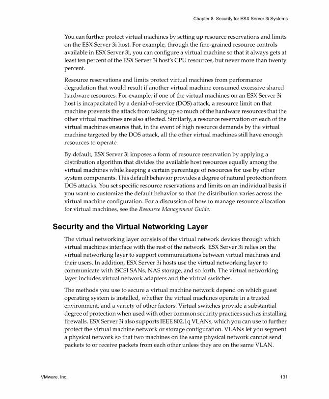
VMware, Inc. 131
Chapter 8 Security for ESX Server 3i Systems
You can further protect virtual machines by setting up resource reservations and limits on the ESX Server 3i host. For example, through the fine‐grained resource controls available in ESX Server 3i, you can configure a virtual machine so that it always gets at least ten percent of the ESX Server 3i host’s CPU resources, but never more than twenty percent.
Resource reservations and limits protect virtual machines from performance degradation that would result if another virtual machine consumed excessive shared hardware resources. For example, if one of the virtual machines on an ESX Server 3i host is incapacitated by a denial‐of‐service (DOS) attack, a resource limit on that machine prevents the attack from taking up so much of the hardware resources that the other virtual machines are also affected. Similarly, a resource reservation on each of the virtual machines ensures that, in the event of high resource demands by the virtual machine targeted by the DOS attack, all the other virtual machines still have enough resources to operate.
By default, ESX Server 3i imposes a form of resource reservation by applying a distribution algorithm that divides the available host resources equally among the virtual machines while keeping a certain percentage of resources for use by other system components. This default behavior provides a degree of natural protection from DOS attacks. You set specific resource reservations and limits on an individual basis if you want to customize the default behavior so that the distribution varies across the virtual machine configuration. For a discussion of how to manage resource allocation for virtual machines, see the Resource Management Guide.
Security and the Virtual Networking LayerThe virtual networking layer consists of the virtual network devices through which virtual machines interface with the rest of the network. ESX Server 3i relies on the virtual networking layer to support communications between virtual machines and their users. In addition, ESX Server 3i hosts use the virtual networking layer to communicate with iSCSI SANs, NAS storage, and so forth. The virtual networking layer includes virtual network adapters and the virtual switches.
The methods you use to secure a virtual machine network depend on which guest operating system is installed, whether the virtual machines operate in a trusted environment, and a variety of other factors. Virtual switches provide a substantial degree of protection when used with other common security practices such as installing firewalls. ESX Server 3i also supports IEEE 802.1q VLANs, which you can use to further protect the virtual machine network or storage configuration. VLANs let you segment a physical network so that two machines on the same physical network cannot send packets to or receive packets from each other unless they are on the same VLAN.

ESX Server 3i Configuration Guide
132 VMware, Inc.
You can get a sense of how to use virtual switches to implement security tools like DMZs and configure virtual machines on different networks within the same ESX Server 3i host by reviewing the following examples.
For a specific discussion of how virtual switches and VLANs help safeguard the virtual machine network and a discussion of other security recommendations for virtual machine networks, see “Securing Virtual Machines with VLANs” on page 149.
Example: Creating a Network DMZ Within a Single ESX Server 3i Host
One example of how to leverage ESX Server 3i isolation and virtual networking features to configure a secure environment is the creation of a network demilitarized zone (DMZ) on a single ESX Server 3i host, as shown in Figure 8‐4.
Figure 8-4. DMZ Configured Within a Single ESX Server 3i Host
This configuration includes four virtual machines configured to create a virtual DMZ on Virtual Switch 2. Virtual Machine 1 and Virtual Machine 4 run firewalls and are connected to virtual adapters through virtual switches. Both of these virtual machines are multihomed. Of the remaining two virtual machines, Virtual Machine 2 runs a Web server and Virtual Machine 3 runs as an application server. Both these virtual machines are single homed.
hardware networkadapter 1
External Network Internal Network
hardware networkadapter 2
ESX Server
Virtual Machine 1
firewall server web server application server firewall server
virtual switch 1 virtual switch 2 virtual switch 3
Virtual Machine 2 Virtual Machine 3 Virtual Machine 4
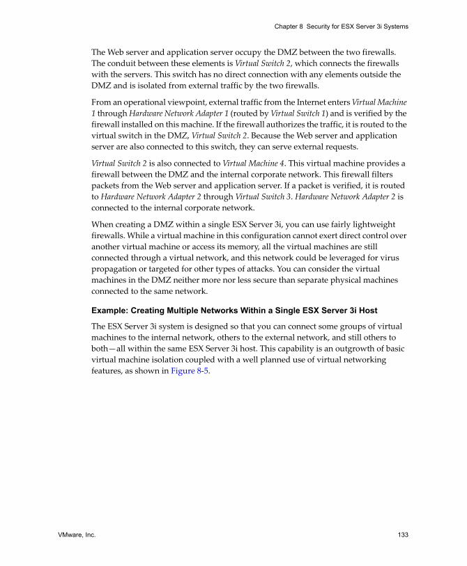
VMware, Inc. 133
Chapter 8 Security for ESX Server 3i Systems
The Web server and application server occupy the DMZ between the two firewalls. The conduit between these elements is Virtual Switch 2, which connects the firewalls with the servers. This switch has no direct connection with any elements outside the DMZ and is isolated from external traffic by the two firewalls.
From an operational viewpoint, external traffic from the Internet enters Virtual Machine 1 through Hardware Network Adapter 1 (routed by Virtual Switch 1) and is verified by the firewall installed on this machine. If the firewall authorizes the traffic, it is routed to the virtual switch in the DMZ, Virtual Switch 2. Because the Web server and application server are also connected to this switch, they can serve external requests.
Virtual Switch 2 is also connected to Virtual Machine 4. This virtual machine provides a firewall between the DMZ and the internal corporate network. This firewall filters packets from the Web server and application server. If a packet is verified, it is routed to Hardware Network Adapter 2 through Virtual Switch 3. Hardware Network Adapter 2 is connected to the internal corporate network.
When creating a DMZ within a single ESX Server 3i, you can use fairly lightweight firewalls. While a virtual machine in this configuration cannot exert direct control over another virtual machine or access its memory, all the virtual machines are still connected through a virtual network, and this network could be leveraged for virus propagation or targeted for other types of attacks. You can consider the virtual machines in the DMZ neither more nor less secure than separate physical machines connected to the same network.
Example: Creating Multiple Networks Within a Single ESX Server 3i Host
The ESX Server 3i system is designed so that you can connect some groups of virtual machines to the internal network, others to the external network, and still others to both—all within the same ESX Server 3i host. This capability is an outgrowth of basic virtual machine isolation coupled with a well planned use of virtual networking features, as shown in Figure 8‐5.

ESX Server 3i Configuration Guide
134 VMware, Inc.
Figure 8-5. External Networks, Internal Networks, and a DMZ Configured Within a Single ESX Server 3i Host
physical networkadapters
ExternalNetwork 1
InternalNetwork 2
ExternalNetwork 2
InternalNetwork 1
ESX Server
VM 2
internaluser
VM 3
internaluser
VM 4
internaluser
VM 5
internaluser
VM 6
firewallserver
VM 7
Webserver
VM 8
firewallserver
VM 1
FTP server
Internal NetworkExternal Network DMZ

VMware, Inc. 135
Chapter 8 Security for ESX Server 3i Systems
Here, the system administrator configured an ESX Server 3i host into three distinct virtual machine zones, each serving a unique function:
FTP server – Virtual Machine 1 is configured with FTP software and acts as a holding area for data sent to and from outside resources such as forms and collateral localized by a vendor.
This virtual machine is associated with an external network only. It has its own virtual switch and physical network adapter that connect it to External Network 1. This network is dedicated to servers that the company uses to receive data from outside sources. For example, the company uses External Network 1 to receive FTP traffic from vendors and allow vendors access to data stored on externally available servers though FTP. In addition to servicing Virtual Machine 1, External Network 1 services FTP servers configured on different ESX Server 3i hosts throughout the site.
Because Virtual Machine 1 doesn’t share a virtual switch or physical network adapter with any virtual machines in the host, the other resident virtual machines cannot transmit packets to or receive packets from Virtual Machine 1’s network. This prevents sniffing attacks, which require sending network traffic to the victim. More importantly, an attacker cannot leverage the natural vulnerability of FTP to access any of the host’s other virtual machines.
Internal virtual machines – Virtual Machines 2 – 5 are reserved for internal use. These virtual machines process and store company‐private data such as medical records, legal settlements, and fraud investigations. As a result, the system administrators must ensure the highest level of protection for these virtual machines.
These virtual machines connect to Internal Network 2 through their own virtual switch and network adapter. Internal Network 2 is reserved for internal use by personnel such as claims processors, in‐house lawyers, or adjustors.
Virtual Machines 2 – 5 can communicate with one another through the virtual switch and with internal virtual machines elsewhere on Internal Network 2 through the physical network adapter. They cannot communicate with externally‐facing machines. As with the FTP server, these virtual machines cannot send packets to or receive packets from the other virtual machines’ networks. Similarly, the host’s other virtual machines cannot send packets to or receive packets from Virtual Machines 2 – 5.

ESX Server 3i Configuration Guide
136 VMware, Inc.
DMZ – Virtual Machines 6 – 8 are configured as a DMZ that the marketing group uses to publish the company’s external Web site.
This group of virtual machines is associated with External Network 2 and Internal Network 1. The company uses External Network 2 to support the Web servers used by the marketing and financial department to host the corporate Web site and other Web facilities that it hosts to outside users. Internal Network 1 is the conduit that the marketing department uses to publish web pages to the corporate Web site, post downloads, and maintain services like user forums.
Because these networks are separate from External Network 1 and Internal Network 2 and the virtual machines have no shared points of contact (switches or adapters), there is no risk of attack to or from the FTP Server or the internal virtual machine group.
For an example of configuring a DMZ with virtual machines, see “Example: Creating a Network DMZ Within a Single ESX Server 3i Host” on page 132.
By capitalizing on virtual machine isolation, correctly configuring virtual switches, and maintaining network separation, the system administrator can house all three virtual machine zones in the same ESX Server 3i host and be confident that there will be no data or resource breaches.
The company enforces isolation among the virtual machine groups by using multiple internal and external networks and making sure that the virtual switches and physical network adapters for each group are completely separate from those of other groups.
Because none of the virtual switches straddle virtual machine zones, the system administrator succeeds in eliminating the risk of packet leakage from one zone to another. A virtual switch, by design, cannot leak packets directly to another virtual switch. The only way for packets to travel from one virtual switch to another is if:
The virtual switches are connected to the same physical LAN.
The virtual switches connect to a common virtual machine, which could then be used to transmit packets.
Neither of these conditions occur in sample configuration. If the system administrator wants to verify that no common virtual switch paths exist, he or she can check for possible shared points of contact by reviewing the network switch layout in the VI Client. For information on the virtual switch layout, see “Virtual Switches” on page 21.

VMware, Inc. 137
Chapter 8 Security for ESX Server 3i Systems
To safeguard the virtual machines’ resources, the system administrator lowers the risk of DOS and DDOS attacks by configuring a resource reservation and limit for each virtual machine. The system administrator further protects the ESX Server 3i host and virtual machines by installing software firewalls at the front and back ends of the DMZ, ensuring that the ESX Server 3i host is behind a physical firewall, and configuring the networked storage resources so that each has its own virtual switch.
Security Resources and InformationYou can find additional information on security topics through the following resources.Table 8-1. VMware Security Resources on the Web
Topic Resource
VMware security policy, up‐to‐date security alerts, security downloads, and focus discussions of security topics
http://www.vmware.com/vmtn
Corporate security response policy http://www.vmware.com/support/policies/security_response.html VMware is committed to helping you maintain a secure environment. To reassure you that any security issues will be corrected in a timely fashion, the VMware Security Response Policy states our commitment to resolve possible vulnerabilities in our products.
Certification of VMware products http://www.vmware.com/security/ Search for the term “VMware” on this site to find the certification status of specific VMware products.
Third‐party software support policy http://www.vmware.com/support/policies VMware supports a variety of storage systems, software agents such as backup agents, system management agents, and so forth. You can find lists of agents, tools, and other software supported by ESX Server 3i by searching http://www.vmware.com/vmtn/resources for ESX Server 3i compatibility guides. The industry offers more products and configurations than VMware can test. If VMware does not list a product or configuration in a compatibility guide, Technical Support will attempt to help you with any problems, but cannot guarantee that the product or configuration can be used. Always evaluate any security risks for unsupported products or configurations carefully.

ESX Server 3i Configuration Guide
138 VMware, Inc.

VMware, Inc. 139
9
This chapter describes measures you can take to promote a secure environment for your ESX Server 3i hosts, virtual machines, and iSCSI SANs. The discussion focuses on network configuration planning from a security perspective and the steps you can take to protect the components in your configuration from attack.
This chapter covers the following topics:
“Securing the Network with Firewalls” on page 139
“Securing Virtual Machines with VLANs” on page 149
“Securing Virtual Switch Ports” on page 155
“Securing iSCSI Storage” on page 157
Securing the Network with FirewallsSecurity administrators use firewalls to safeguard the network or selected components within the network from intrusion. Firewalls regulate network traffic by allowing or denying the passage of messages based on a set of criteria. For example, some firewalls only allow traffic through on a specified set of ports. Firewalls are especially beneficial to servers running more services and sending and receiving large amounts of diverse network traffic.
Some versions of ESX Server include a firewall, but ESX Server 3i does not. This is because ESX Server 3i runs a limited set of well known services, and ESX Server 3i prevents the addition of further services. With such restrictions, the factors that necessitate a firewall are significantly reduced.
Securing an ESX Server 3i Configuration 9

ESX Server 3i Configuration Guide
140 VMware, Inc.
While no firewall is integrated in to ESX Server 3i, VMware recommends you deploy a set of security technologies that is appropriate to your needs. For example, you may elect to install a firewall to filter traffic entering and leaving the network segment on which you have installed ESX Server 3i.
In a virtual machine environment, you can plan your layout for firewalls between:
Physical machines such as VirtualCenter Management Server hosts and ESX Server 3i hosts.
One virtual machine and another—for example, between a virtual machine acting as an external Web server and a virtual machine connected to your company’s internal network.
A physical machine and a virtual machine as when you place a firewall between a physical network adapter card and a virtual machine.
How you utilize firewalls in an ESX Server 3i configuration is based on how you plan to use the network and how secure any given component needs to be. For example, if you create a virtual network where each virtual machine is dedicated to running a different benchmark test suite for the same department, the risk of unwanted access from one virtual machine to the next is minimal. Hence, you have little need to set up the configuration so that firewalls are present between the virtual machines. However, to prevent interruption of a test run from an outside host, you might set up the configuration so that a firewall is present at the entry point of the virtual network to protect the entire set of virtual machines.
This section shows firewall placement for configurations with and without VirtualCenter. It also provides information on the firewall ports required for ESX Server 3i systems.
Firewalls for Configurations with a VirtualCenter ServerIf you use a VirtualCenter Server, you can install firewalls at any of the locations shown in Figure 9‐1.
NOTE Depending on your configuration, you might not need all the firewalls in the illustration, or you might need firewalls in locations not shown.

VMware, Inc. 141
Chapter 9 Securing an ESX Server 3i Configuration
Figure 9-1. Sample Virtual Infrastructure Network Configuration and Traffic Flow
Networks configured with a VirtualCenter Server can receive communications through several types of clients: the VI Client or third‐party network management clients that use the SDK to interface with the host. During normal operation, VirtualCenter listens for data from its managed hosts and clients on designated ports. VirtualCenter also assumes that its managed hosts listen for data from VirtualCenter on designated ports. If a firewall is present between any of these elements, you must ensure that there are open ports in the firewall to support data transfer.
VirtualCenterServer
ESX Server 3i ESX Server 3
VirtualCenter
LicenseServer
VI Web AccessVI Clientthird-party networkmanagement tool
storage
firewall
Ports 902, 2050-2250, 8000, and
8042-8045
Port 27010Port 27000 Port 902
Port 902 Port 443firewall
firewall
Ports 443,902, and 903
Ports 443,902, and 903

ESX Server 3i Configuration Guide
142 VMware, Inc.
If you access ESX Server 3i hosts through a VirtualCenter Server, you typically protect the VirtualCenter Server using a firewall. This firewall provides basic protection for your network. Whether this firewall lies between the clients and the VirtualCenter Server or both the VirtualCenter Server and the clients are behind the firewall depends on your deployment. The main thing is to ensure that a firewall is present at what you consider to be an entry point for the system as a whole.
You might also include firewalls at a variety of other access points in the network, depending on how you plan to use the network and how secure the various devices need to be. Select the locations for your firewalls based on the security risks that you’ve identified for your network configuration. The following is a list of firewall locations common to ESX Server 3i implementations. Many of the firewall locations in the list and illustration are optional.
Between the VI Client or a third‐party network management client and the VirtualCenter Server.
If your users access virtual machines through the VI Client, between the VI Client and the ESX Server 3i host. This connection is in addition to the connection between the VI Client and the VirtualCenter Server, and it requires a different port.
Between the license server and either the VirtualCenter Server or the ESX Server 3i host. Typically, in configurations that include a VirtualCenter Server, the license server runs on the same physical machine as does the VirtualCenter Server. In this case, the license server connects to the ESX Server 3i network through a firewall, running in parallel with the VirtualCenter Server but using different ports.
In some configurations, you might use an external license server—for example, if your company wants to control all licenses through a single, dedicated appliance. Here, you would connect the license server to the VirtualCenter Server through a firewall between these two servers.
Regardless of how you set up the license server connection, the ports you use for license traffic are the same. For information on licensing, see the Installation and Upgrade Guide.
Between the VirtualCenter Server and the ESX Server 3i hosts.
Between the ESX Server 3i hosts in your network. Although traffic between ESX Server 3i hosts is usually considered trusted, you can add firewalls between your ESX Server 3i hosts if you are concerned about security breaches from machine to machine.

VMware, Inc. 143
Chapter 9 Securing an ESX Server 3i Configuration
If you add firewalls between ESX Server 3i hosts and plan to migrate virtual machines between the servers, perform cloning, or use VMotion, you must also open ports in any firewall that divides the source host from the target hosts so that the source and targets can communicate.
Between the ESX Server 3i hosts and network storage devices such as NFS or iSCSI storage. These ports are not specific to VMware, and you configure them according to the specifications for your network.
For information on the ports to open for these communications paths, see “TCP and UDP Ports for Management Access” on page 144.
Firewalls for Configurations Without a VirtualCenter ServerIf you connect clients directly to your ESX Server 3i network instead of using a VirtualCenter Server, your firewall configuration is somewhat simpler. You might install firewalls at any of the locations shown in Figure 9‐2.
Figure 9-2. Firewall Configuration for ESX Server 3i Networks Managed Directly by a Client
NOTE Depending on your configuration, you might not need all the firewalls in the illustration, or you might need firewalls in locations not shown.
ESX Server 1 ESX Server 2
VI Clientthird-party networkmanagement tool
storage
firewall
Ports 902, 2050-2250, 8000, and
8042-8045
Port 902 Port 903 Port 443firewall

ESX Server 3i Configuration Guide
144 VMware, Inc.
Networks configured without a VirtualCenter Server receive communications through the same types of clients as they do if a VirtualCenter Server were present: VI Clients or third‐party network management clients.
Just as you would for configurations that include a VirtualCenter Server, you should be sure a firewall is present to protect your ESX Server 3i layer or, depending on your configuration, your clients and ESX Server 3i layer. This firewall provides basic protection for your network. The firewall ports you use are the same as those you use if a VirtualCenter Server is in place.
Licensing in this type of configuration is part of the ESX Server 3i package that you install on each of the ESX Server 3i hosts. Because licensing is resident to the server, you do not need to install a separate license server. This eliminates the need for a firewall between the license server and the ESX Server 3i network.
In some situations, you might want to centralize your licenses. You can choose to maintain a separate license server or house the license server on one of the ESX Server 3i hosts in your network. With either of these approaches, you connect the license server to the ESX Server 3i network through a firewall using the ports normally reserved for virtual machine licensing, much as you do if a VirtualCenter Server is present. Configurations that use a license server other than the one automatically installed on the ESX Server 3i host require additional setup.
TCP and UDP Ports for Management AccessThis section lists predetermined TCP and UDP ports used for management access to your VirtualCenter Server, ESX Server 3i hosts, and other network components. If you need to manage network components from outside a firewall, you might need to reconfigure the firewall to allow access on the appropriate ports.
Table 9-1. TCP and UDP Ports
Port Purpose Traffic Type
80 HTTP access.The default non‐secure TCP Web port typically used in conjunction with port 443 as a front end for access to ESX Server 3i networks from the Web. Port 80 redirects traffic to an HTTPS landing page (port 443) from which you launch your virtual machine console.WS‐Management uses port 80.
Incoming TCP
427 The CIM client uses the Service Location Protocol, version 2 (SLPv2) to find CIM servers.
Incoming and outgoing UDP

VMware, Inc. 145
Chapter 9 Securing an ESX Server 3i Configuration
443 HTTPS access.The default SSL Web port. Use Port 443 for the following:
VI Client access to the VirtualCenter Server.Direct VI Client access to ESX Server 3i hosts. WS‐Management.VMware Update Manager.VMware Converter.
Incoming TCP
902 Authentication traffic and remote console traffic.Use Port 902 for the following:
VirtualCenter Server access to ESX Server 3i hosts. VirtualCenter Server sends UDP messages from ESX Server 3i hosts on port 902.ESX Server 3i host access to other ESX Server 3i hosts for migration and provisioning. ESX Server 3i sends UDP messages to VirtualCenter Server on ports 902.VI Client access to virtual machine consoles.
Incoming and outgoing TCP, outgoing UDP
2049 Transactions from your NFS storage devices.This port is used on the VMkernel interface.
Incoming and outgoing TCP
2050–2250 Traffic between ESX Server 3i hosts for VMware High Availability (HA) and EMC Autostart Manager.
Outgoing TCP, incoming and outgoing UDP
3260 Transactions from your iSCSI storage devices.This port is used on the VMkernel interface.
Outgoing TCP
5900‐5906 RFB protocol which is used by management tools such as VNC. Incoming and outgoing TCP
5988 CIM XML transactions over HTTPS. (SEE UPDATE) Incoming and outgoing TCP
5989 CIM XML transactions over HTTP. (SEE UPDATE) Incoming and outgoing TCP
8000 Incoming requests from VMotion. Incoming and outgoing TCP
8042–8045 Traffic between ESX Server 3i hosts for HA and EMC Autostart Manager.
Outgoing TCP, incoming and outgoing UDP
27000 License transactions from ESX Server 3i to the license server (lmgrd.exe)
Outgoing TCP
27010 License transactions from ESX Server 3i to the license server (vmwarelm.exe).
Outgoing TCP
Table 9-1. TCP and UDP Ports (Continued)
Port Purpose Traffic Type

ESX Server 3i Configuration Guide
146 VMware, Inc.
In addition to the TCP and UDP ports just discussed, you can configure other ports depending on your needs.
You can use VI Client to open ports for installed management agents and supported services such as SSH, NFS, and so forth. For information on configuring additional ports for these services, see “Configuring Firewalls for Supported Services and Management Agents” on page 148.
Connecting to VirtualCenter Server Through a FirewallAs shown in Table 9‐1, the port that VirtualCenter Server uses to listen for data transfer from its clients is 443. If you have a firewall between your VirtualCenter Server and its clients, you must configure a connection through which the VirtualCenter Server can receive data from the clients.
To enable the VirtualCenter Server to receive data from a VI Client, open port 443 in the firewall to allow data transfer from the VI Client to the VirtualCenter Server. Contact the firewall system administrator for additional information on configuring ports in a firewall.
If you are using the VI Client and don’t want to use port 443 as the port for the VI Client‐to‐VirtualCenter Server communication, you can switch to another port by changing the VirtualCenter settings in the VI Client. To learn how to change these settings, see the Basic System Administration Guide.
Connecting to the Virtual Machine Console Through a FirewallWhether you connect your client to ESX Server 3i hosts through a VirtualCenter Server or use a direct connection to the ESX Server 3i host, certain ports are required for user and administrator communication with virtual machine consoles. These ports support different client functions, interface with different layers within ESX Server 3i, and use different authentication protocols. They are:
Port 902 – Port 902 is the port that the VirtualCenter Server assumes is available for receiving data from the ESX Server 3i host. VMware does not support configuring a different port for this connection. Port 902 connects the VirtualCenter Server to the ESX Server 3i host through the VMware Authorization Daemon (vmware‐authd). This daemon then multiplexes port 902 data to the appropriate recipient for processing.

VMware, Inc. 147
Chapter 9 Securing an ESX Server 3i Configuration
The VI Client uses this port to provide a connection for guest operating system mouse/keyboard/screen (MKS) activities on virtual machines. It is through this port that users interact with the virtual machine guest operating systems and applications. Port 902 is the port that the VI Client assumes is available when interacting with virtual machines. VMware doesn’t support configuring a different port for this function.
Port 443 – The VI Client and SDK use this port to send data to the VirtualCenter managed hosts. Also, the VI Client and SDK, when connected directly to an ESX Server 3i host, use this port to support any management functions related to the server and its virtual machines. Port 443 is the port that clients assume is available when sending data to the ESX Server 3i host. VMware doesn’t support configuring a different port for these connections.
Port 443 connects clients to the ESX Server 3i host through the SDK. The vmware-hostd multiplexes port 443 data to the appropriate recipient for processing.
Figure 9‐3 shows the relationships between VI Client functions, ports, and ESX Server 3i processes.
Figure 9-3. Port Usage for VI Client Communications with ESX Server 3i
If you have a firewall between your VirtualCenter Server and VirtualCenter managed host, open Ports 443 and 902 in the firewall to allow data transfer to:
ESX Server
VI Client
Port 443
vmware-hostd vmware-authd
virtual machinemanagement functions
virtual machineconsole
firewall Port 902

ESX Server 3i Configuration Guide
148 VMware, Inc.
ESX Server 3i hosts from the VirtualCenter Server.
ESX Server 3i hosts directly from the VI Client.
Refer to the firewall system administrator for additional information on configuring the ports.
Connecting ESX Server 3i Hosts Through FirewallsIf you have a firewall between two ESX Server 3i hosts and you want to allow transactions between the hosts or use VirtualCenter to perform any source/target activities, such as VMware High Availability (HA) traffic, migration, cloning, or VMotion, you must configure a connection through which the managed hosts can receive data. To do so, you open ports in the following ranges:
902 (server‐to‐server migration and provisioning traffic)
2050–2250 (for HA traffic)
8000 (for VMotion)
8042–8045 (for HA traffic)
Refer to the firewall system administrator for additional information on configuring the ports. For more detailed information on the directionality and protocol for these ports, see “TCP and UDP Ports for Management Access” on page 144.
Configuring Firewalls for Supported Services and Management Agents
While ESX Server 3i has no firewall itself, you must configure any other firewalls in your environment to accept commonly supported services and installed management agents. The following is a list of services and agents that are commonly present in a Virtual Infrastructure environment:
NFS client (insecure service)
NTP client
iSCSI software client
CIM HTTP server (insecure service)
CIM HTTPS server
Syslog client
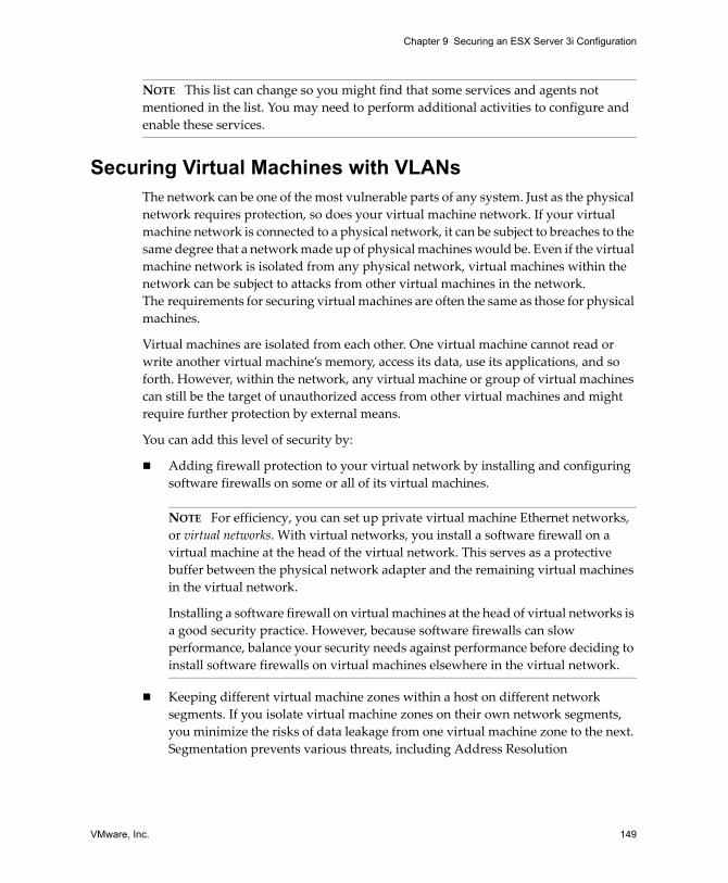
VMware, Inc. 149
Chapter 9 Securing an ESX Server 3i Configuration
Securing Virtual Machines with VLANsThe network can be one of the most vulnerable parts of any system. Just as the physical network requires protection, so does your virtual machine network. If your virtual machine network is connected to a physical network, it can be subject to breaches to the same degree that a network made up of physical machines would be. Even if the virtual machine network is isolated from any physical network, virtual machines within the network can be subject to attacks from other virtual machines in the network. The requirements for securing virtual machines are often the same as those for physical machines.
Virtual machines are isolated from each other. One virtual machine cannot read or write another virtual machine’s memory, access its data, use its applications, and so forth. However, within the network, any virtual machine or group of virtual machines can still be the target of unauthorized access from other virtual machines and might require further protection by external means.
You can add this level of security by:
Adding firewall protection to your virtual network by installing and configuring software firewalls on some or all of its virtual machines.
Keeping different virtual machine zones within a host on different network segments. If you isolate virtual machine zones on their own network segments, you minimize the risks of data leakage from one virtual machine zone to the next. Segmentation prevents various threats, including Address Resolution
NOTE This list can change so you might find that some services and agents not mentioned in the list. You may need to perform additional activities to configure and enable these services.
NOTE For efficiency, you can set up private virtual machine Ethernet networks, or virtual networks. With virtual networks, you install a software firewall on a virtual machine at the head of the virtual network. This serves as a protective buffer between the physical network adapter and the remaining virtual machines in the virtual network.
Installing a software firewall on virtual machines at the head of virtual networks is a good security practice. However, because software firewalls can slow performance, balance your security needs against performance before deciding to install software firewalls on virtual machines elsewhere in the virtual network.

ESX Server 3i Configuration Guide
150 VMware, Inc.
Protocol (ARP) spoofing in which an attacker manipulates the ARP table to remap MAC and IP addresses, thereby gaining access to network traffic to and from a host. Attackers use ARP spoofing to generate denials of service, hijack the target system, and otherwise disrupt the virtual network.
Planning segmentation carefully lowers the chances of packet transmissions between virtual machine zones, thus preventing sniffing attacks, which require sending network traffic to the victim. Also, an attacker cannot leverage an insecure service in one virtual machine zone to access other virtual machine zones in the host. You can implement segmentation using either of two approaches, each of which has different benefits.
Use separate physical network adapters for virtual machine zones to ensure that the zones are isolated. Maintaining separate physical network adapters for virtual machine zones is probably the most secure method and is less prone to misconfiguration after the initial segment creation.
Set up Virtual Local Area Networks (VLANs) to help safeguard your network. Because VLANs provide the almost all of the security benefits inherent in implementing physically separate networks without the hardware overhead, they offer a viable solution that can save you the cost of deploying and maintaining additional devices, cabling, and so forth.
VLANs are an IEEE standard networking scheme with specific tagging methods that allow routing of packets to only those ports that are part of the VLAN. When properly configured, VLANs provide a dependable means for you to protect a set of virtual machines from accidental or malicious intrusions.
VLANs let you segment a physical network so that two machines in the network are unable to transmit packets back and forth unless they are part of the same VLAN. For example, accounting records and transactions are among a company’s most sensitive internal information. In a company whose sales, shipping, and accounting employees all use virtual machines in the same physical network, you might protect the virtual machines for the accounting department by setting up VLANs as shown in Figure 9‐4.

VMware, Inc. 151
Chapter 9 Securing an ESX Server 3i Configuration
Figure 9-4. Sample VLAN Layout
In this configuration, all employees in the accounting department use virtual machines in VLAN A and the employees in sales use virtual machines in VLAN B.
The router forwards packets containing accounting data to the switches. These packets are tagged for distribution to VLAN A only. Therefore, the data is confined to Broadcast Domain A, and cannot be routed to Broadcast Domain B unless the router is configured to do so.
This VLAN configuration prevents the sales force from intercepting packets destined for the accounting department. It also prevents the accounting department from receiving packets intended for the sales group. Note that the virtual machines serviced by a single virtual switch can be in different VLANs.
The following section provides suggestions for securing your network through virtual switches and VLANs.
VM 3 VM 4
vSwitch
VM 5
vSwitch
VM 6 VM 7 VM 8
vSwitch
VM 0 VM 1 VM 2
vSwitch
VM 9 VM 10 VM 11
VM 12VLAN
B
VM 13VLAN
A
VM 14VLAN
B
vSwitch
Router
Host 1
Host 3
Host 4
Host 2
Switch 1
Switch 2Multiple VLANson the samevirtual switch
BroadcastDomains A and B
VLAN A
BroadcastDomain A
VLAN B
BroadcastDomain B

ESX Server 3i Configuration Guide
152 VMware, Inc.
Security Considerations for VLANsESX Server 3i features a complete IEEE 802.1q‐compliant VLAN implementation. The way you set up VLANs to secure parts of a network depends on factors such as the guest operating system you install, the way your network equipment is configured, and so forth. While VMware cannot make specific recommendations on how to set up VLANs, the following topics describe some factors to consider when using a VLAN deployment as part of your security enforcement policy.
Treat VLANs as part of a broader security implementation
VLANs are an effective means of controlling where and how widely data is transmitted within the network. If an attacker gains access to the network, the attack is likely to be limited to the VLAN that served as the entry point, lessening the risk to the network as a whole.
VLANs provide protection only in that they control how data is routed and contained after it passes through the switches and enters the network. You can use VLANs to help secure Layer 2 of your network architecture—the data link layer. However, configuring VLANs doesn’t protect the physical layer of your network model or any of the other layers. Even if you create VLANs, you should provide additional protection by securing your hardware (routers, hubs, and so forth) and encrypting data transmissions.
VLANs are not a substitute for firewalls in your virtual machine configurations. Most network configurations that include VLANs also include software firewalls. If you include VLANs in your virtual network, be sure that any firewalls you install are VLAN‐aware.
Be sure your VLANs are properly configured
Equipment misconfiguration and network hardware, firmware, or software defects can make a VLAN susceptible to VLAN hopping attacks. VLAN hopping occurs when an attacker with authorized access to one VLAN creates packets that trick physical switches into transmitting the packets to another VLAN that the attacker is not authorized to access. Vulnerability to this type of attack usually results from a switch being misconfigured for native VLAN operation, in which the switch can receive and transmit untagged packets.
To help prevent VLAN hopping, keep your equipment up to date by installing hardware and firmware updates as they become available. Also, be sure to follow your vendor’s best practice guidelines when configuring your equipment.

VMware, Inc. 153
Chapter 9 Securing an ESX Server 3i Configuration
Be aware that VMware virtual switches don’t support the concept of a native VLAN. All data passed on these switches is appropriately tagged. However, because there might be other switches in the network that are configured for native VLAN operation, VLANs configured with virtual switches can still be vulnerable to VLAN hopping.
If you plan to use VLANs to enforce network security, VMware recommends that you disable the native VLAN feature for all switches unless you have a compelling need to operate some of your VLANs in native mode. If you need to use native VLAN, pay attention to your switch vendor’s configuration guidelines for this feature.
Virtual Switch Protection and VLANsVMware virtual switches provide safeguards against certain threats to VLAN security. Because of the way that virtual switches are designed, they protect VLANs against a variety of attacks, many of which involve VLAN hopping. Having this protection does not guarantee that your virtual machine configuration is invulnerable to other types of attacks. For example, virtual switches do not protect the physical network against these attacks, just the virtual network.
The following topics give you an idea of some attacks virtual switches and VLANs can protect against.
MAC flooding
These attacks flood a switch with packets containing MAC addresses tagged as having come from different sources. Many switches use a Content‐Addressable Memory (CAM) table to learn and store the source address for each packet. When the table is full, the switch may enter a fully open state in which every incoming packet is broadcast on all ports, letting the attacker see all the switch’s traffic. This state might result in packet leakage across VLANs.
While VMware virtual switches store a MAC address table, they don’t get the MAC addresses from observable traffic and are not vulnerable to this type of attack.
802.1q and ISL tagging attacks
These attacks force a switch to redirect frames from one VLAN to another by tricking the switch into acting as a trunk and broadcasting the traffic to other VLANs.
VMware virtual switches don’t perform the dynamic trunking required for this type of attack and, therefore, are not vulnerable.

ESX Server 3i Configuration Guide
154 VMware, Inc.
Double-encapsulation attacks
These attacks occur when an attacker creates a double‐encapsulated packet in which the VLAN identifier in the inner tag is different from the VLAN identifier in the outer tag. For backward compatibility, native VLANs strip the outer tag from transmitted packets unless configured to do otherwise. When a native VLAN switch strips the outer tag, only the inner tag is left, and that inner tag routes the packet to a different VLAN than the one identified in the now‐missing outer tag.
VMware virtual switches drop any double‐encapsulated frames that a virtual machine attempts to send on a port configured for a specific VLAN. Therefore, they are not vulnerable to this type of attack.
Multicast brute-force attacks
These attacks involve sending large numbers of multicast frames to a known VLAN almost simultaneously in hopes of overloading the switch so that it mistakenly allows some of the frames to broadcast to other VLANs.
VMware virtual switches do not allow frames to leave their correct broadcast domain (VLAN) and are not vulnerable to this type of attack.
Spanning-tree attacks
These attacks target Spanning‐Tree Protocol (STP), which is used to control bridging between parts of the LAN. The attacker sends Bridge Protocol Data Unit (BPDU) packets that attempt to change the network topology, establishing himself or herself as the root bridge. As the root bridge, the attacker can sniff the contents of transmitted frames.
VMware virtual switches don’t support STP and are not vulnerable to this type of attack.
Random frame attacks
These attacks involve sending large numbers of packets in which the source and destination addresses stay the same, but in which fields are randomly changed in length, type, or content. The goal of this attack is to force packets to be mistakenly rerouted to a different VLAN.
VMware virtual switches are not vulnerable to this type of attack.
Because new security threats develop over time, do not consider this an exhaustive list of attacks. Regularly check VMware security resources on the Web (http://www.vmware.com/security/) to learn about security, recent security alerts, and VMware security tactics.

VMware, Inc. 155
Chapter 9 Securing an ESX Server 3i Configuration
Securing Virtual Switch PortsAs with physical network adapters, a virtual network adapter can send frames that appear to be from a different machine or impersonate another machine so that it is able to receive network frames intended for that machine. Also, like physical network adapters, a virtual network adapter can be configured such that it receives frames targeted for other machines.
When you create a virtual switch for your network, you add port groups to impose a policy configuration for the virtual machines, storage systems, and so forth attached to the switch. You create virtual ports through the VI Client.
As part of adding a port or port group to a virtual switch, the VI Client configures a security profile for the port. You can use this security profile to ensure that ESX Server 3i prevents the guest operating systems for its virtual machines from impersonating other machines on the network. This security feature is implemented so that the guest operating system responsible for the impersonation does not detect that the impersonation has been prevented.
The security profile determines how strongly you enforce protection against impersonation and interception attacks on virtual machines. To correctly use the settings in the security profile, you need to understand the basics of how virtual network adapters control transmissions and how attacks are staged at this level.
Each virtual network adapter has its own MAC address assigned when the adapter is created. This address is called the initial MAC address. Although the initial MAC address can be reconfigured from outside the guest operating system, it cannot be changed by the guest operating system. In addition, each adapter has an effective MAC address that filters out incoming network traffic with a destination MAC address different from the effective MAC address. The guest operating system is responsible for setting the effective MAC address and typically matches the effective MAC address to the initial MAC address.
When sending packets, an operating system typically places its own network adapterʹs effective MAC address in the source MAC address field of the Ethernet frame. It also places the MAC address for the receiving network adapter in the destination MAC address field. The receiving adapter accepts packets only when the destination MAC address in the packet matches its own effective MAC address.

ESX Server 3i Configuration Guide
156 VMware, Inc.
Upon creation, a network adapter’s effective MAC address and initial MAC address are the same. The virtual machine’s operating system can alter the effective MAC address to another value at any time. If an operating system changes the effective MAC address, its network adapter then receives network traffic destined for the new MAC address. The operating system can send frames with an impersonated source MAC address at any time. Thus, an operating system can stage malicious attacks on the devices in a network by impersonating a network adapter authorized by the receiving network.
You can use virtual switch security profiles on ESX Server 3i hosts protect against this type of attack by setting three options.
MAC address changes
By default, this option is set to Accept, meaning that the ESX Server 3i host accepts requests to change the effective MAC address to other than the initial MAC address. The MAC Address Changes option setting affects traffic received by a virtual machine.
To protect against MAC impersonation, you can set this option to Reject. If you do, the ESX Server 3i host does not honor requests to change the effective MAC address to anything other than the initial MAC address. Instead, the port that the virtual adapter used to send the request is disabled. As a result, the virtual adapter does not receive any more frames until it changes the effective MAC address to match the initial MAC address. The guest operating system does not detect that the MAC address change has not been honored.
MAC address changes settings affect traffic leaving a virtual machine. MAC address changes will occur if the sender is permitted to make them, even if vSwitches or a receiving virtual machine does not permit MAC address changes.
Forged transmissions
By default, this option is set to Accept, meaning the ESX Server 3i host does not compare source and effective MAC addresses. The Forged Trasmits option setting affects traffic transmitted from a virtual machine.
NOTE In some situations, you might have a legitimate need for more than one adapter to have the same MAC address on a network—for example, if you are using Microsoft Network Load Balancing in unicast mode. Note that when Microsoft Network Load Balancing is used in the standard multicast mode, adapters do not share MAC addresses.

VMware, Inc. 157
Chapter 9 Securing an ESX Server 3i Configuration
To protect against MAC impersonation, you can set this option to Reject. If you do, the ESX Server 3i host compares the source MAC address being transmitted by the operating system with the effective MAC address for its adapter to see if they match. If the addresses don’t match, ESX Server 3i drops the packet.
The guest operating system does not detect that its virtual network adapter cannot send packets using the impersonated MAC address. The ESX Server 3i host intercepts any packets with impersonated addresses before they are delivered, and the guest operating system might assume that the packets have been dropped.
Promiscuous mode operation
By default, this option is set to Reject, meaning that the virtual network adapter cannot operate in promiscuous mode. Promiscuous mode eliminates any reception filtering that the virtual network adapter would perform so that every frame that the guest operating system receives all traffic observed on the wire.
While promiscuous mode can be useful for tracking network activity, it is an insecure mode of operation because any adapter in promiscuous mode had access to the packets regardless of whether some of the packets should be received only by a particular network adapter. This means that an administrator or root user within a virtual machine can potentially view traffic destined for other guest or host operating systems.
If you need to change any of these default settings for a port, you must modify the security profile by editing virtual switch settings in the VI Client. For information on editing these settings, see “Virtual Switch Policies” on page 36.
Securing iSCSI StorageThe storage you configure for an ESX Server 3i host might include one or more storage area networks (SANs) that use iSCSI. iSCSI is a means of accessing SCSI devices and exchanging data records using TCP/IP protocol over a network port rather than through a direct connection to a SCSI device. In iSCSI transactions, blocks of raw SCSI data are encapsulated in iSCSI records and transmitted to the requesting device or user.
NOTE In some situations, you might have a legitimate need to configure a virtual switch to operate in promiscuous mode—for example, if you are running network intrusion detection software or a packet sniffer.

ESX Server 3i Configuration Guide
158 VMware, Inc.
iSCSI SANs let you make efficient use of existing Ethernet infrastructures to provide ESX Server 3i hosts access to storage resources that they can dynamically share. As such, iSCSI SANs provide an economical storage solution for environments that rely on a common storage pool to serve numerous users. As with any networked system, your iSCSI SANs can be subject to security breaches. When you configure iSCSI on an ESX Server 3i host, you can take several measures to minimize security risks.
The following section tells you how to configure authentication for iSCSI SANs and provides suggestions for securing iSCSI SANs. The section covers the following topics:
“Securing iSCSI Devices Through Authentication” on page 158
“Protecting an iSCSI SAN” on page 161
Securing iSCSI Devices Through AuthenticationOne means of securing iSCSI devices from unwanted intrusion is to require that the ESX Server 3i host, or initiator, be authenticated by the iSCSI device, or target, whenever the host attempts to access data on the target LUN. The goal of authentication is to prove that the initiator has the right to access a target, a right granted when you configure authentication.
You have two choices when setting up authentication for iSCSI SANs on the ESX Server 3i host.
Challenge Handshake Authentication Protocol (CHAP)
You can configure the iSCSI SAN to use CHAP authentication. In CHAP authentication, when the initiator contacts an iSCSI target, the target sends a predefined ID value and a random value, or key, to the initiator. The initiator then creates a one‐way hash value that it sends to the target. The hash contains three elements: a predefined ID value, the random value sent by the target, and a private value, or CHAP secret, shared by the initiator and target. When the target receives the hash from the initiator, it creates its own hash value using the same elements and compares it to the initiator’s hash. If the results match, the target authenticates the initiator.
ESX Server 3i supports one‐way CHAP authentication for iSCSI. It does not support bi‐directional CHAP. In one‐way CHAP authentication, the target authenticates the initiator, but the initiator does not authenticate the target. The initiator has only one set of credentials, and these credentials are used by all the iSCSI targets.
NOTE The requirements and procedures for securing an iSCSI SAN are similar for the hardware iSCSI adapters you can use with ESX Server 3i hosts and for iSCSI configured directly through the ESX Server 3i host.

VMware, Inc. 159
Chapter 9 Securing an ESX Server 3i Configuration
ESX Server 3i supports CHAP authentication at the HBA level only. It does not support per‐target CHAP authentication, which enables you to configure different credentials for each target to achieve greater target refinement.
Disabled
You can configure the iSCSI SAN to use no authentication. Be aware that communications between the initiator and target are still authenticated in a rudimentary way because the iSCSI target devices are typically set up to communicate with specific initiators only.
Choosing not to enforce more stringent authentication can make sense if your iSCSI storage is housed in one location and you create a dedicated network or VLAN to service all your iSCSI devices. The premise here is that the iSCSI configuration is secure because it is isolated from any unwanted access, much as a Fibre Channel SAN would be.
As a basic rule, disable authentication only if you are willing to risk an attack to the iSCSI SAN or cope with problems that result from human error.
ESX Server 3i does not support Kerberos, Secure Remote Protocol (SRP), or public key authentication methods for iSCSI. Additionally, it does not support IPsec authentication and encryption.
You use the VI Client to determine whether authentication is currently being performed and to configure the authentication method.
To check the authentication method
1 Log on to the VI Client and select the server from the inventory panel.
2 Click the Configuration tab and click Storage Adapters.
3 Select the iSCSI adapter you want to check and click Properties to open the iSCSI Initiator Properties dialog box.
4 Click CHAP Authentication.
If CHAP Name shows a name—often the iSCSI initiator name, the iSCSI SAN is using CHAP authentication, as shown below.
5 Click Close.
NOTE If CHAP Name shows Not Specified, the iSCSI SAN is not using CHAP authentication.

ESX Server 3i Configuration Guide
160 VMware, Inc.
To configure iSCSI for CHAP authentication
1 Log on to the VI Client and select the server from the inventory panel.
2 Click the Configuration tab and click Storage Adapters.
3 Select the iSCSI adapter and click Properties to open the iSCSI Initiator Properties dialog box.
4 Click CHAP Authentication > Configure to open the CHAP Authentication dialog box.
5 Click Use the following CHAP credentials.
6 Perform one of the following actions:
To set the CHAP name to the iSCSI adapter name, select Use initiator name.
To set the CHAP name to anything other than the iSCSI adapter name, deselect Use initiator name and enter a name of up to 255 alphanumeric characters in the CHAP Name field.
7 Enter a CHAP secret to be used as part of authentication.
The secret you enter is a text string.
8 Click OK.
NOTE The VI Client doesn’t impose a minimum or maximum length for the CHAP secret you enter. However, some iSCSI storage devices require that the secret exceed a minimum number of characters or have limitations on the character types you can use. Check the manufacturer’s documentation to determine the requirements.

VMware, Inc. 161
Chapter 9 Securing an ESX Server 3i Configuration
To disable iSCSI authentication
1 Log on to the VI Client and select the server from the inventory panel.
2 Click the Configuration tab and click Storage Adapters.
3 Select the iSCSI adapter and click Properties to open the iSCSI Initiator Properties dialog box.
4 Click CHAP Authentication > Configure to open the CHAP Authentication dialog box.
5 Select Disable CHAP authentication.
6 Click OK.
Protecting an iSCSI SANWhen planning your iSCSI configuration, you should take measures to improve the overall security of the iSCSI SAN. Your iSCSI configuration is only as secure as your IP network, so by enforcing good security standards when setting up your network, you help safeguard your iSCSI storage.
Protecting transmitted data
A primary security risk in iSCSI SANs is that an attacker might sniff transmitted storage data.
VMware recommends that you take additional measures to prevent attackers from easily seeing iSCSI data. Neither the hardware iSCSI adapter nor the ESX Server 3i host iSCSI initiator encrypts the data they transmit to and from the targets, making the data more vulnerable to sniffing attacks.

ESX Server 3i Configuration Guide
162 VMware, Inc.
Allowing your virtual machines to share virtual switches and VLANs with your iSCSI configuration potentially exposes iSCSI traffic to misuse by a virtual machine attacker. To help ensure that intruders can’t listen to iSCSI transmissions, make sure that none of your virtual machines can see the iSCSI storage network.
If you use a hardware iSCSI adapter, you can accomplish this by making sure that the iSCSI adapter and ESX physical network adapter are not inadvertently connected outside the host by virtue of sharing a switch or some other means. If you configure iSCSI directly through the ESX Server 3i host, you can accomplish this by configuring iSCSI storage through a different virtual switch than the one used by your virtual machines, as shown in Figure 9‐5.
Figure 9-5. iSCSI Storage on a Separate Virtual Switch
In addition to protecting the iSCSI SAN by giving it a dedicated virtual switch, consider configuring your iSCSI SAN on its own VLAN. Placing your iSCSI configuration on a separate VLAN ensures that no devices other than the iSCSI adapter have visibility into transmissions within the iSCSI SAN.
Securing iSCSI ports
When you run iSCSI devices, the ESX Server 3i host doesn’t open any ports that listen for network connections. This measure reduces the chances that an intruder can break into the ESX Server 3i host through spare ports and gain control over the host. Therefore, running iSCSI doesn’t present any additional security risks at the ESX Server 3i host end of the connection.

VMware, Inc. 163
Chapter 9 Securing an ESX Server 3i Configuration
Be aware that any iSCSI target device that you run must have one or more open TCP ports used to listen for iSCSI connections. If any security vulnerabilities exist in the iSCSI device software, your data can be at risk through no fault of ESX Server 3i. To lower this risk, install all security patches provided by your storage equipment manufacturer and limit the devices connected to the iSCSI network.

ESX Server 3i Configuration Guide
164 VMware, Inc.

VMware, Inc. 165
10
This chapter explains how ESX Server 3i handles user authentication and shows you how to set up user and group permissions. In addition, it discusses encryption for connections to the VI Client and SDK as well as configuring a delegate user name for transactions with NFS storage.
This chapter discusses the following topics:
“Securing ESX Server 3i Through Authentication and Permissions” on page 165
“Encryption and Security Certificates for ESX Server 3i” on page 178
“Virtual Machine Delegates for NFS Storage” on page 183
Securing ESX Server 3i Through Authentication and Permissions
ESX Server 3i authenticates users accessing ESX Server 3i hosts using the VI Client or or SDK. The default installation of ESX Server 3i uses a local password database for authentication. Every time a VI Client or VirtualCenter user connects to an ESX Server 3i host, a connection is established with the VMware Host Agent (vmware-hostd) process. The vmware-hostd uses user names and passwords for authentication.
Authentication and User Management 10

ESX Server 3i Configuration Guide
166 VMware, Inc.
Figure 10‐1 shows how ESX Server 3i authenticates transactions from the VI Client.
Figure 10-1. Authentication for VI Client Communications with ESX Server 3i
ESX Server 3i authentication transactions with third‐party network management clients are similarly direct interactions with the vmware-hostd process.
To make sure that authentication works efficiently for your site, you might need to perform basic tasks such as setting up users, groups, permissions, and roles, configuring user attributes, adding your own certificates, determining whether you want to use SSL, and so forth.
About Users, Groups, Permissions, and RolesAccess to an ESX Server 3i host and its resources is granted when a known user with appropriate permissions logs on to the host with a password that matches the one stored for that user. VirtualCenter uses a similar approach when determining whether to grant access to a user. VirtualCenter and ESX Server 3i hosts determine the level of access for the user based on the permissions assigned to the user. For example, one user might have permissions that allow him or her to create virtual machines on the host and another user might have permissions that allow him or her to power on virtual machines but not create them.
The combination of user name, password, and permissions is the mechanism by which VirtualCenter and ESX Server 3i hosts authenticate a user for access and authorize the user to perform activities. To support this mechanism, the VirtualCenter and ESX Server 3i hosts maintain lists of authorized users, their passwords, and the permissions assigned to each user.
ESX Server 3i
VI Client
vmware-hostd
management functions
console
user name/passwordauthentication

VMware, Inc. 167
Chapter 10 Authentication and User Management
VirtualCenter and ESX Server 3i hosts deny access under the following circumstances:
A user not in the user list attempts to log on.
A user enters the wrong password.
A user is in the list but has not been assigned permissions.
A user who successfully logged on attempts operations that he or she does not have permission to perform.
As part of managing ESX Server 3i hosts and VirtualCenter, you need to develop user and permission models, which are basic plans for how you want to handle particular types of users and how you want to design your permissions. In developing your user and permission models, be aware that:
ESX Server 3i and VirtualCenter use sets of privileges, or roles, to control which operations individual users or groups can perform. ESX Server 3i and VirtualCenter provide you with a set of pre‐established roles, but you can also create new ones.
You can manage users more easily by assigning them to groups. If you create groups, you can apply a role to the group, and this role is inherited by all the users in the group.
Understanding Users
A user is an individual authorized to log on to either an ESX Server 3i host or to VirtualCenter. ESX Server 3i users fall into two categories: those who can access the ESX Server 3i host through VirtualCenter and those who can access the ESX Server 3i host by directly logging on to the host from the VI Client, a third‐party client, or a command shell. These two categories draw users from different sources.
VirtualCenter users – Authorized users for VirtualCenter are those included in the Windows domain list referenced by VirtualCenter or are local Windows users on the VirtualCenter host.
You cannot use VirtualCenter to manually create, remove, or otherwise change users. To manipulate the user list or change user passwords, you must do so through the tools you use to manage your Windows domain.
Any changes you make to the Windows domain are reflected in VirtualCenter. However, because you cannot directly manage users in VirtualCenter, the user interface doesn’t provide a user list for you to review. The only time you work with user and group lists is when you select users and groups during role assignment. You will notice these changes only when you select users in order to configure permissions.

ESX Server 3i Configuration Guide
168 VMware, Inc.
Direct access users – Users authorized to work directly on an ESX Server 3i host are those added to the internal user list by a system administrator.
If you log on to the host as an administrator, you can perform a variety of management activities for these users, such as changing passwords, group memberships, permissions, and so forth. You can also add and remove users.
The user list maintained by VirtualCenter is completely separate from the user list maintained by the ESX Server 3i host. Even if the lists maintained by a host and VirtualCenter appear to have common users (for instance, a user called devuser), these users should be treated as separate users who happen to have the same name. The attributes of devuser in VirtualCenter, including permissions, passwords, and so forth are separate from the attributes of devuser on the ESX Server 3i host. If you log on to VirtualCenter as devuser, you might have permission to view and delete files from a datastore, whereas if you log on to an ESX Server 3i host as devuser, you might not.
Because of the confusion that duplicate naming can cause, VMware recommends that you check the VirtualCenter user list before you create ESX Server 3i host users so that you can avoid creating host users that have the same name as VirtualCenter users. To check for VirtualCenter users, review the Windows domain list.
Understanding Groups
You can more efficiently manage some user attributes by creating groups. A group is a set of users that you want to manage through a common set of rules and permissions. When you assign permissions to a group, they are inherited by all users in the group, and you do not have to work with the user profiles one by one. Therefore, using groups can significantly reduce the time it takes to set up your permissions model and improve future scalability.
As an administrator, you need to decide how to structure groups to achieve your security and usage goals. For example, three part‐time sales team members work different days, and you want them to share a single virtual machine but not use the virtual machines belonging to sales managers. In this case, you might create a group called SalesShare that includes the three sales people: Mary, John, and Tom. You might then give the SalesShare group permission to interact with only one object, Virtual Machine A. Mary, John, and Tom inherit these permissions and are able to power up Virtual Machine A, start console sessions on Virtual Machine A, and so forth. They cannot perform these actions on the sales managers’ virtual machines: Virtual Machines B, C, and D.

VMware, Inc. 169
Chapter 10 Authentication and User Management
The group lists in VirtualCenter and an ESX Server 3i host are drawn from the same sources as their respective user lists. If you are working through VirtualCenter, the group list is called from the Windows domain. If you are logged on to an ESX Server 3i host directly, the group list is called from a table maintained by the host. All the recommendations for how you treat group lists are the same as those for user lists.
Understanding Permissions
For ESX Server 3i and VirtualCenter, permissions are defined as access roles that consist of a user and the user’s assigned role for an object such as a virtual machine or ESX Server 3i host. Permissions grant users the right to perform specific activities and manage specific objects on an ESX Server 3i host or, if users are working from VirtualCenter, all VirtualCenter‐managed objects. For example, to configure memory for an ESX Server 3i host, you must have a permission that grants host configuration privileges.
Most VirtualCenter and ESX Server 3i users have limited ability to manipulate the objects associated with the host. However, users in the Administrator role have full access rights and permissions on all virtual objects such as datastores, hosts, virtual machines, and resource pools. By default, the Administrator role is granted to the root user; if the host is managed by VirtualCenter, vpxuser is also an Administrator user. Administrator users have permissions described in the following topics.
root
The root user can perform a complete range of control activities on the specific ESX Server 3i host that he or she is logged on to, including manipulating permissions, creating groups and users, working with events, and so forth. A root user logged on to one ESX Server 3i host cannot control the activities of any other host in the broader ESX Server 3i deployment.
For security reasons, you might not want to use the root user in the Administrator role. In this case, you can change permissions after installation so that the root user no longer has administrative privileges or you can delete the root user’s access permissions altogether through the VI Client as described in the “Managing Users, Groups, Permissions, and Roles” chapter of Basic System Administration. If you do so, you must first create another permission at the root level that has a different user assigned to the Administrator role.
Assigning the Administrator role to a different user helps you maintain security through traceability. The VI Client logs all actions initiated by the Administrator role user as events, providing you with an audit trail. You can use this feature to improve accountability among the various users who act as administrators for the host. If all the

ESX Server 3i Configuration Guide
170 VMware, Inc.
administrators log on to the host as the root user, you cannot tell which administrator performed an action. If, instead, you create multiple permissions at the root level—each associated with a different user or user group—you can track the actions of each administrator or administrative group.
After you create an alternative Administrator user, you can safely delete the root user’s permissions or change its role to limit its privileges. If you delete or change the root user’s permissions, you must use the new user you created as the host authentication point when you bring the host under VirtualCenter management.
vpxuser
This user is VirtualCenter acting as an entity with Administrator rights on the ESX Server 3i host, allowing it to manage activities for that host. vpxuser is created at the time that an ESX Server 3i host is attached to VirtualCenter. It is not present on the ESX Server 3i host unless the host is being managed through VirtualCenter.
When an ESX Server 3i host is managed through VirtualCenter, VirtualCenter has Administrator privileges on the host. For example, VirtualCenter can move virtual machines to and from hosts and perform configuration changes needed to support virtual machines.
The VirtualCenter administrator, through vpxuser, can perform most of the same tasks on the host as the root user and also schedule tasks, work with templates, and so forth. However, there are certain activities you cannot perform as a VirtualCenter administrator. These activities, which include directly creating, deleting, or editing users and groups for ESX Server 3i hosts, can be performed only by a user with Administrator permissions directly on each ESX Server 3i host.
NOTE Configuration commands that you run through the command line interface (vicfg commands) do not perform an access check. Therefore, even if you limit the root user’s privileges, this does not affect what that user can do using the command line interface commands.
CAUTION Do not change vpxuser in any way and do not change its permissions. If you do so, you might experience problems in working with the ESX Server 3i host through VirtualCenter.

VMware, Inc. 171
Chapter 10 Authentication and User Management
dcui
The dcui user runs on hosts and acts with Administrator rights. This user’s primary purpose is to configure hosts for lock‐down mode from the direct console. This user is used as an agent for the direct console and should not be modified or used by interactive users.
If you are acting in the Administrator role on an ESX Server 3i host, you can grant permissions to individual users and groups on that host If you are acting in the Administrator role in VirtualCenter, you can grant permissions to any user or group included in the Windows domain list referenced by VirtualCenter.
VirtualCenter registers any selected Windows domain user or group through the process of assigning permissions. By default, all users who are members of the local Windows Administrators group on the VirtualCenter Server are granted the same access rights as any user assigned to the Administrator role. Users who are members of the Administrators group can log on as individuals and have full access.
For security reasons, consider removing the Windows Administrators group from the Administrator role. You can change permissions after installation so the Windows Administrators group does not have administrative privileges. Alternately you can use VI Client to delete the Windows Administrators group access permissions. If you delete Windows Administrators access permissions, you must first create another permission at the root level that has a different user assigned to the Administrator role.
Users that are not assigned the administrator role cannot login to the local console if they are not a member of local administrators group. To grant access to the local console, use the following command, where username is the name of the user to be granted access:
usermod -G localadmin username
The method you use to configure permissions directly on an ESX Server 3i host is identical to the method you use to configure permissions in VirtualCenter. Also, the list of privileges is the same for both ESX Server 3i and VirtualCenter.
For information on configuring permissions and to read about the privileges you can assign, see Basic System Administration.
CAUTION Do not change dcui user in any way and do not change its permissions. If you do so, you might experience problems in working with the ESX Server 3i host through the local UI.

ESX Server 3i Configuration Guide
172 VMware, Inc.
Understanding Roles
VirtualCenter and ESX Server 3i grant access to objects only to users who have been assigned permissions for the object. When you assign a user or group permissions for the object, you do so by pairing the user or group with a role. A role is a pre‐defined set of privileges.
ESX Server 3i hosts provide three default roles, and you cannot change the privileges associated with these roles. Each subsequent default role includes the privileges of the previous role. For example, the Administrator role inherits the privileges of the Read Only role. Roles you create yourself do not inherit privileges from any of the default roles. The default roles are discussed in the following topics.
No Access
Users assigned this role for an object cannot view or change the object in any way. For example, a user who has a No Access role for a particular virtual machine cannot see the virtual machine in the VI Client inventory when he or she logs on to the ESX Server 3i host. With a No Access role for a particular object, a user can select the VI Client tabs associated with the no‐access object, but the tab displays no content. For example, if the user doesn’t have access to any virtual machines, he or she can select the Virtual Machines tab but won’t see a virtual machine listing on the tab or any status information—the table is blank.
The No Access role is the default assigned to any user or group you create on an ESX Server 3i host. You can elevate or lower a newly created user’s or group’s role on an object‐by‐object basis.
Read Only
Users assigned this role for an object are allowed to view the state of the object and details about the object.
With this role, a user can view virtual machine, host, and resource pool attributes. The user cannot view the remote console for a host. All actions through the menus and toolbars are disallowed.
NOTE The root user, dcui user, and vpxuser are the only users not assigned the No Access role by default. Instead, they are assigned the Administrator role.
You can delete the root user’s permissions altogether or change its role to No Access as long as you first create a replacement permission at the root level with the Administrator role and associate this role with a different user. If you delete or change the root user’s permissions, you must use the new user you created as the host authentication point when you bring the host under VirtualCenter management.

VMware, Inc. 173
Chapter 10 Authentication and User Management
Administrator
Users assigned this role for an object are allowed to view and perform all actions on the object. This role also includes all permissions inherent in the Read Only role.
You can create custom roles by using the role‐editing facilities in the VI Client to create privilege sets that match your user needs. If you use the VI Client connected to VirtualCenter to manage your ESX Server 3i hosts, you have additional roles to choose from in VirtualCenter. Also, the roles you create directly on an ESX Server 3i host are not accessible within VirtualCenter. You can work with these roles only if you log on to the host directly from the VI Client.
If you manage ESX Server 3i hosts through VirtualCenter, be aware that maintaining custom roles in both the host and VirtualCenter can result in confusion and misuse. In this type of configuration, VMware recommends that you maintain custom roles only in VirtualCenter. For information on creating, altering, and deleting roles as well as a discussion of additional roles available in VirtualCenter, see Basic System Administration.
Working with Users and Groups on ESX Server 3i HostsIf you are directly connected to an ESX Server 3i host through the VI Client, you can create, edit, and delete users and groups. These users and groups are visible in the VI Client whenever you log on to the ESX Server 3i host but are not available if you log on to VirtualCenter.
The following section explains how to work with users and groups in the VI Client directly connected to an ESX Server 3i host. The section covers basic tasks you can perform for users and groups, such as viewing and sorting information and exporting reports. It also shows you how to create, delete, and edit users and groups.
Viewing and Exporting Users and Group Information
You work with users and groups through the Users & Groups tab in the VI Client. This tab displays a Users table or Groups table depending on whether you click the Users button or Groups button.
NOTE You can also create roles and set permissions through a direct connection to the ESX Server 3i host. Because these tasks are more widely performed in VirtualCenter, see Basic System Administration for information on working with permissions and roles.

ESX Server 3i Configuration Guide
174 VMware, Inc.
Figure 10‐2 shows the Users table. The Groups table is similar.
Figure 10-2. Users Table
You can sort the lists according to column, show and hide columns, and export the list in formats you can use when preparing reports or publishing user or group lists on the Web.
To view and sort ESX Server 3i users or groups
1 Log on to the VI Client through the ESX Server 3i host.
2 Select the server from the inventory panel.
3 Click the Users & Groups tab and click Users or Groups.
4 Perform any of these actions as appropriate:
To sort the table by any of the columns, click the column heading.
To show or hide columns, right‐click any of the column headings and select or deselect the name of the column you want to hide.
To export data in the ESX Server 3i Users or Groups table
1 Log on to the VI Client through the ESX Server 3i host.
2 Select the server from the inventory panel.
3 Click the Users & Groups tab and click Users or Groups.
4 Determine how you want the table sorted, and hide or show columns according to the information you want to see in the exported file.
5 Right‐click anywhere in the user table and click Export to open the Save As dialog box.
6 Select a path and enter a filename.

VMware, Inc. 175
Chapter 10 Authentication and User Management
7 Select the file type.
You can export the user or group table in any of the following formats:
HTML (plain HTML or HTML formatted for use with a CSS style sheet)
XML
Microsoft Excel
CSV (Comma Separated Values)
8 Click OK.
Working with the Users Table
You can add users to the Users table for an ESX Server 3i host, remove users, and change various user attributes such as password and group memberships. When you perform these activities, you are altering the internal user list maintained by the ESX Server 3i host.
To add a user to the ESX Server 3i Users table
1 Log on to the VI Client through the ESX Server 3i host.
2 Select the server from the inventory panel.
3 Click the Users & Groups tab and click Users.
4 Right‐click anywhere in the Users table and click Add to open the Add New User dialog box.
5 Enter a login, a user name, a numeric user ID (UID), and a password.
Specifying the user name and UID are optional. If you don’t specify the UID, the VI Client assigns the next available UID.
6 For each existing group you want the user to be part of, enter the group name and click Add.
If you type a nonexistent group name, the VI Client warns you and does not add the group to the Group membership list.
7 Click OK.
The login and user name you entered now appear in the Users table.

ESX Server 3i Configuration Guide
176 VMware, Inc.
To modify the settings for a user
1 Log on to the VI Client through the ESX Server 3i host.
2 Select the server from the inventory panel.
3 Click the Users & Groups tab and click Users.
4 Right‐click the user to be modified and click Edit to open the Edit User dialog box.
5 To change the user ID, enter a numeric user UID in the UID field.
The VI Client assigns the UID when you first create the user. In most cases, this assignment doesn’t need to be changed.
6 Enter a new user name.
7 To change the user’s password, select Change Password and enter the new password.
The password should be long and complex enough to protect against common brute force attacks.
8 To add the user to another group, enter the group name and click Add.
If you type a nonexistent group name, the VI Client warns you and does not add the group to the Group membership list.
9 To remove the user from a group, select the group name from the list and click Remove.
10 Click OK.
To remove a user from the ESX Server 3i Users table
1 Log on to the VI Client through the ESX Server 3i host.
2 Select the server from the inventory panel.
3 Click the Users & Groups tab and click Users.
4 Right‐click the user you want to remove and click Remove.
Working with the Groups Table
You can add groups to the Groups table for an ESX Server 3i host, remove groups, and add or remove group members. When you perform these activities, you are altering the internal group list maintained by the ESX Server 3i host.
CAUTION Do not remove the root user.

VMware, Inc. 177
Chapter 10 Authentication and User Management
To add a group to the ESX Server 3i Groups table
1 Log on to the VI Client through the ESX Server 3i host.
2 Select the server from the inventory panel.
3 Click the Users & Groups tab and click Groups.
4 Right‐click anywhere in the Groups table and click Add to open the Create New Group dialog box.
5 Enter a group name and numeric group ID (GID).
Specifying the GID is optional. If you don’t specify a GID, the VI Client assigns the next available group ID.
6 For each user that you want as a group member, enter the user name and click Add.
If you type a nonexistent user name, the VI Client warns you and does not add the user to the Users in this group list.
7 Click OK.
The group ID and group name you entered now appear in the Groups table.
To add or remove users from a group
1 Log on to the VI Client through the ESX Server 3i host.
2 Select the server from the inventory panel.
3 Click the Users & Groups tab and click Groups.
4 Right‐click the group to be modified and click Edit to open the Edit Group dialog box.
5 To add a user to the group, enter the user name and click Add.
If you type a nonexistent user name, the VI Client warns you and does not add the user to the Users in this group list.
6 To remove a user from the group, select the user name from the list and click Remove.
7 Click OK.

ESX Server 3i Configuration Guide
178 VMware, Inc.
To remove a group from the ESX Server 3i Groups table
1 Log on to the VI Client through the ESX Server 3i host.
2 Select the server from the inventory panel.
3 Click the Users & Groups tab and click Groups.
4 Right‐click the group you want to remove and click Remove.
Encryption and Security Certificates for ESX Server 3iESX Server supports SSL v3 and TLS v1, generally referred to here as SSL. SSL helps secure communications. If SSL is enabled, all network traffic is encrypted as long as the following conditions are true:
You have not changed the Web proxy service to allow unencrypted traffic for the port.
(SEE UPDATE) SSL is not enabled by default, so network traffic is not encrypted unless you take action. SSL does protect the initial connection between VI Clients and VirtualCenter, but subsequent communications are not encrypted. To fully enable the security provided by certificates in ESX Server 3, you must enable certificate checking and install new certificates.
To enable certificate checking
1 Log on to a VirtualCenter server using the VI Client.
2 Click Administration > Virtual Center Management Server Configuration.
The Virtual Center Management Server Configuration dialog appears.
3 Click SSL Settings in the left pane and enable the Check host certificates checkbox.
4 Click OK.
(SEE UPDATE) To receive the full benefit of certificate checking, install new certificates. The initial certificates are created by ESX Server and stored on the host. If a server’s certificate becomes unusable, you can generate a new certificate.
CAUTION Do not remove the root user.

VMware, Inc. 179
Chapter 10 Authentication and User Management
To generate new certificates for the ESX Server 3i host
1 Invoke the Reset Customized Settings in the local console.
2 Reboot the system.
Certificates are regenerated.
The ESX Server 3i host uses automatically generated self‐signed certificates that are created as part of the installation process. These certificates make it possible to begin using the server, but using self‐signed certificates may not comply with the security policy of your organization. The security policy of some organizations mandate the purchase and use of a certificate from a trusted certificate authority as a replacement for the automatically generated certificate. Using untrusted SSL certificates may result in security warnings.
Figure 10-3. Security Warning
To address this issue, add a certificate that is signed by a recognized certificate authority.
(SEE UPDATE) In addition to the vifs command, you can also use third party applications to upload certificates. Applications that support HTTP PUT operations work with the HTTP interface that is included with ESX Server 3i. For example, you can use SeaMonkey Composer to upload a certificate and key. (SEE UPDATE)
To use vifs to replace the existing certificate with a CA-signed certificate
1 Use the vifs command to put a copy of the certificate and key files on the ESX Server. The form this command takes for the certificate and key respectively is:
vifs --server hostname --username username --put /host/host/ssl_crt rui.crt
vifs --server hostname --username username --put /host/host/ssl_key rui.key

ESX Server 3i Configuration Guide
180 VMware, Inc.
2 Use the ̋ Restart Management Agentsʺ operation through the local console to make the settings take effect. The restart management agents appears as follows:
To upload a certificate and key using a HTTP PUT
1 Open the file to be uploaded in the application you are using to upload files.
2 Use the application to publish the file.
Publish certs to https://hostname/host/ssl_crt.
Publish keys to https://hostname/host/sslkey.
3 Use the ̋ Restart Management Agentsʺ operation through the local console to make the settings take effect.
Modifying ESX Server 3i Web Proxy SettingsIn thinking about encryption and user security, be aware of the following:
(SEE UPDATE) ESX Server 3i doesn’t handle pass phrases, also known as encrypted keys. If you set up a pass phrase, ESX Server 3i processes will be unable to start correctly, so avoid setting up certificates using pass phrases.
You can configure the Web proxy so that it searches for certificates in a location other than the default location. This capability proves useful for companies that prefer to centralize their certificates on a single machine so the certificates can be used by multiple hosts.
To support encryption for user names, passwords, and packets, SSL is enabled by default for VMware Infrastructure SDK connections. If you want to configure the these connections so that they don’t encrypt transmissions, disable SSL for your VMware Infrastructure SDK connection by switching the connection from HTTPS
CAUTION Certificates stored in a location other the ESX Server 3 host are unusable if the host loses network connectivity. If certificate checking is enabled, you cannot establish secure connections with guests.

VMware, Inc. 181
Chapter 10 Authentication and User Management
to HTTP as described in “To change security settings for a Web proxy service” on page 181. Consider disabling SSL only if you have created a fully trusted environment for clients, meaning that firewalls are in place and transmissions to and from the host are fully isolated. Disabling SSL can improve performance because you avoid the overhead required to perform encryption.
To protect against misuse of ESX Server 3i services, most internal ESX Server 3i services are accessible only through port 443, the port used for HTTPS transmission. Port 443 acts as a reverse proxy for ESX Server 3i. You can see a list of services on ESX Server 3i through an HTTP welcome page, but you can’t directly access the Storage Adapters services without proper authorization. You can change this configuration so that individual services are directly accessible through HTTP connections. VMware recommends that you not make this change unless you are using ESX Server 3i in a fully trusted environment.
When you upgrade VirtualCenter, the certificate remains in place. (SEE UPDATE)
To change security settings for a Web proxy service
1 Use the vifs command to get a copy of the proxy.xml file for editing. The form this command takes is:
vifs --server hostname --username username --get /host/proxy.xml proxy.xml
For details on using vifs, see the Remote Command‐Line Interface Installation and Reference Guide.
2 Use a text editor to open the proxy.xml file. Contents of the file typically appears as follows:
<ConfigRoot> <EndpointList>
<_length>6</_length><_type>vim.ProxyService.EndpointSpec[]</_type><e id="0">
<_type>vim.ProxyService.NamedPipeServiceSpec</_type><accessMode>httpsWithRedirect</accessMode><pipeName>/var/run/vmware/proxy-webserver</pipeName><serverNamespace>/</serverNamespace>
</e><e id="1">
<_type>vim.ProxyService.NamedPipeServiceSpec</_type>
CAUTION If this file is changed to an incorrect configuration, the system may enter an unmangeable state. Such a state may only be resolvable through a factory reset using the DCUI.

ESX Server 3i Configuration Guide
182 VMware, Inc.
<accessMode>httpsWithRedirect</accessMode><pipeName>/var/run/vmware/proxy-sdk</pipeName><serverNamespace>/sdk</serverNamespace>
</e><e id="2">
<_type>vim.ProxyService.LocalServiceSpec</_type><accessMode>httpsWithRedirect</accessMode><port>8080</port><serverNamespace>/ui</serverNamespace>
</e><e id="3">
<_type>vim.ProxyService.NamedPipeServiceSpec</_type><accessMode>httpsOnly</accessMode><pipeName>/var/run/vmware/proxy-vpxa</pipeName><serverNamespace>/vpxa</serverNamespace>
</e><e id="4">
<_type>vim.ProxyService.NamedPipeServiceSpec</_type><accessMode>httpsWithRedirect</accessMode><pipeName>/var/run/vmware/proxy-mob</pipeName><serverNamespace>/mob</serverNamespace>
</e><e id="5">
<_type>vim.ProxyService.LocalServiceSpec</_type><!-- Use this mode for "secure" deployment --><!-- <accessMode>httpsWithRedirect</accessMode> --><!-- Use this mode for "insecure" deployment --><accessMode>httpAndHttps</accessMode><port>8889</port><serverNamespace>/wsman</serverNamespace>
</e></EndpointList>
</ConfigRoot>
3 Change the security settings as required. For example, you might want to modify entries for services that use HTTPS to add the option of HTTP access.
e id is an ID number for the server ID XML tag. ID numbers must be unique within the HTTP area.
_type is the name of the service you are moving, for example /sdk or /mob.
accessmode is the forms of communication the service permits. Acceptable values include:
httpOnly – The service is accessible only over plain‐text HTTP connections.
httpsOnly – The service is accessible only over HTTPS connections.

VMware, Inc. 183
Chapter 10 Authentication and User Management
httpsWithRedirect – The service is accessible only over HTTPS connections. Requests over HTTP will be redirected to the appropriate HTTPS URL.
httpAndHttps – The service is accessible both over HTTP and HTTPS connections.
port is the port number assigned to the service. You can assign a different port number to the service.
namespace is the namespace for the server that provides this service.
4 Save your changes and close the file.
5 Use the vifs command to put a copy of the proxy.xml file back on the ESX Server. The form this command takes is:
vifs --server hostname --username username --put /host/proxy.xml proxy.xml
6 Use the ̋ Restart Management Agentsʺ operation through the local console to make the settings take effect. The restart management agents appears as follows:
Virtual Machine Delegates for NFS StorageTo perform most activities on virtual machines, an ESX Server 3i needs access to virtual machine files. For instance, to power on and off virtual machines the ESX Server 3i must be able to create, manipulate, and delete files on the volume that is storing the virtual disk files.
To create, configure, or administer virtual machines on an NFS datastore, you can do so using the delegate user. The delegate userʹs identity is used by the ESX Server 3i for all I/O requests issued to the underlying file system. The delegate user is experimental and is not officially supported.

ESX Server 3i Configuration Guide
184 VMware, Inc.
By default, the delegate user for the ESX Server 3i host is root. However, having root as the delegate user may not work for all NFS datastores. NFS administrators may export volumes with root squashing enabled. The root squash feature maps root to a user with no significant privileges on the NFS server, limiting the root userʹs abilities. This feature is commonly used to prevent unauthorized access to files on an NFS volume. If the NFS volume was exported with root squash enabled, the NFS server might refuse access to the ESX Server 3i host. To ensure that you can create and manage virtual machines from your host, the NFS administrator must turn off the root squash feature or add the ESX Server 3i host’s physical network adapter to the list of trusted servers.
If the NFS administrator is unwilling to take either of these actions, you can change the delegate user to a different identity through experimental ESX Server 3i functionality. This identity must match the owner of the directory on the NFS server otherwise the ESX Server 3i host will be unable to perform file level operations. To set up a different identity for the delegate user, acquire the following information:
User name of the directory owner
User ID (UID) of the directory owner
Group ID (GID) of the directory owner
Then, use this information to change the delegate user setting for the ESX Server 3i host so that it matches the owner of the directory, enabling NFS datastore to recognize the ESX Server 3i host correctly. The delegate user is configured globally, and the same identity is used to access to every volume.
Setting up the delegate user on an ESX Server 3i host requires that you complete these activities:
From the Users & Groups tab for a VI Client running directly on the ESX Server 3i host, either:
Edit the user named vimuser to add the correct UID and GID. vimuser is an ESX Server 3i host user provided to you as a convenience for setting up delegate users. By default, vimuser has a UID of 12 and a GID of 20.
Add a completely new user to the ESX Server 3i host with the delegate user name, UID, and GID.
You must perform one of these steps regardless of whether you manage the host through a direct connection or through the VirtualCenter Server. Also, you need to make sure that the delegate user (vimuser or a delegate user you create) is identical across all ESX Server 3i hosts that use the NFS datastore. See “Working with the Users Table” on page 175.

VMware, Inc. 185
Chapter 10 Authentication and User Management
Configure a virtual machine delegate as part of the security profile for the host, as described in the procedure that follows. You configure the security profile through VirtualCenter or through a VI Client running directly on the ESX Server 3i host.
To change the virtual machine delegate
1 Log on to the VI Client through the ESX Server 3i host.
2 Select the server from the inventory panel.
The hardware configuration page for this server appears with the Summary tab displayed.
3 Click Enter Maintenance Mode.
4 Click the Configuration tab and click Security Profile.
5 Click Virtual Machine Delegate > Edit to open the Virtual Machine Delegate dialog box.
6 Enter the user name for the delegate user.
7 Click OK.
8 Reboot the ESX Server 3i host.
After you reboot the host, the delegate user setting is visible in both VirtualCenter and the VI Client running directly on the ESX Server 3i host.
CAUTION Changing the delegate user for an ESX Server 3i host is experimental and, currently, VMware does not support this implementation. Use of this functional may result in unexpected behavior.

ESX Server 3i Configuration Guide
186 VMware, Inc.

VMware, Inc. 187
11
The chapter focuses on giving you a better idea of how to secure your ESX Server 3i in particular environments by presenting a series of ESX Server 3i deployment scenarios that you can consider as you plan some of the security features of your own deployment. It also makes some basic security recommendations you can consider when creating and configuring virtual machines.
This chapter discusses the following topics:
“Security Approaches for Common ESX Server 3i Deployments” on page 187
“ESX Server 3i Lockdown Mode” on page 192
“Virtual Machine Recommendations” on page 193
Security Approaches for Common ESX Server 3i Deployments
The complexity of ESX Server 3i deployments can vary significantly depending on the size of your company, the way that data and resources need to be shared with the outside world, whether there are multiple datacenters or just one, and so forth.
Inherent in the following deployments are policies for user access, resource sharing, and security level. By comparing the deployments, you can get a sense of the issues you face in planning security for your own ESX Server 3i deployment.
Security Deployments and Recommendations 11

ESX Server 3i Configuration Guide
188 VMware, Inc.
Single Customer DeploymentIn this deployment, the ESX Server 3i hosts are owned and maintained within a single corporation and single datacenter. No ESX Server 3i resources are shared with outside users. One site administrator maintains the ESX Server 3i hosts, and these hosts run a number of virtual machines.
The deployment does not allow customer administrators, and the site administrator is solely responsible for maintaining the various virtual machines. The corporation staffs a set of system administrators who do not have accounts on the ESX Server 3i host and cannot access any of the ESX Server 3i tools such as VirtualCenter or command line shells for the host. These system administrators have access to virtual machines through the virtual machine console so that they can load software and perform other maintenance tasks inside the virtual machines.
Table 11‐1 shows how you might handle sharing for the components you use and configure for the ESX Server 3i host.
Table 11‐2 shows how you might set up user accounts for the ESX Server 3i host.
Table 11-1. Sharing for Components in a Single Customer Deployment
Function Configuration Comments
Virtual machines share the same physical network?
Yes Configure your virtual machines on the same physical network.
VMFS sharing? Yes All .vmdk files should reside in the same VMFS partition.
Virtual machine memory overcommitment?
Yes Configure the total memory for the virtual machines as greater than the total physical memory.
Table 11-2. User Account Setup in a Single Customer Deployment
User Category Total Number of Accounts
Site administrators 1
Customer administrators 0
System administrators 0
Business users 0

VMware, Inc. 189
Chapter 11 Security Deployments and Recommendations
Table 11‐3 shows the level of access for each user.
Multiple Customer Restricted Deployment In this deployment, the ESX Server 3i hosts are in the same datacenter and are used to serve applications for multiple customers. The site administrator maintains the ESX Server 3i hosts, and these hosts run a number of virtual machines dedicated to the customers. Virtual machines that belong to the various customers can be on the same ESX Server 3i host, but the site administrator restricts resource sharing to prevent rogue interaction.
While there is only one site administrator, several customer administrators maintain the virtual machines assigned to their customers. This deployment also includes customer system administrators who do not have ESX Server 3i accounts but have access to the virtual machines through the virtual machine console so that they can load software and perform other maintenance tasks inside the virtual machines.
Table 11‐4 shows how you might handle sharing for the components you use and configure for the ESX Server 3i host.
Table 11-3. User Access in a Single Customer Deployment
Access Level Site Administrator System Administrator
Root access? Yes No
Virtual machine creation and modification? Yes No
Virtual machine access through the console? Yes Yes
Table 11-4. Sharing for Components in a Multiple Customer Restricted Deployment
Function Configuration Comments
Virtual machines share the same physical network?
Partial Put the virtual machines for each customer on a different physical network. All physical networks are independent of each other.
VMFS sharing? No Each customer has their own VMFS partition and their virtual machine .vmdk files reside exclusively on that partition. The partition can span multiple LUNs.
Virtual machine memory overcommitment?
Yes Configure the total memory for the virtual machines as greater than the total physical memory.

ESX Server 3i Configuration Guide
190 VMware, Inc.
Table 11‐5 shows how you might set up user accounts for the ESX Server 3i host.
Table 11‐6 shows the level of access for each user.
Multiple Customer Open Deployment In this deployment, the ESX Server 3i hosts are in the same datacenter and are used to serve applications for multiple customers. The site administrator maintains the ESX Server 3i hosts, and these hosts run a number of virtual machines dedicated to the customers. Virtual machines that belong to the various customers can be on the same ESX Server 3i host, but there are fewer restrictions on resource sharing.
While there is only one site administrator, several customer administrators maintain the virtual machines assigned to their customers. The deployment also includes customer system administrators who do not have ESX Server 3i accounts but have access to the virtual machines through the virtual machine console so that they can load software and perform other maintenance tasks inside the virtual machines. Lastly, a group of business users who do not have accounts can use virtual machines to run their applications.
Table 11-5. User Account Setup in a Multiple Customer Restricted Deployment
User Category Total Number of Accounts
Site administrators 1
Customer administrators 10
System administrators 0
Business users 0
Table 11-6. User Access in a Multiple Customer Restricted Deployment
Access LevelSite Administrator
Customer Administrator
System Administrator
Root access? Yes No No
Virtual machine creation and modification?
Yes Yes No
Virtual machine access through the console?
Yes Yes Yes

VMware, Inc. 191
Chapter 11 Security Deployments and Recommendations
Table 11‐7 shows how you might handle sharing for the components you use and configure for the ESX Server 3i host.
Table 11‐8 shows how you might set up user accounts for the ESX Server 3i host.
Table 11‐9 shows the level of access for each user.
Table 11-7. Sharing for Components in a Multiple Customer Open Deployment
Function Configuration Comments
Virtual machines share the same physical network?
Yes Configure your virtual machines on the same physical network.
VMFS sharing? Yes Virtual machines can share VMFS partitions and their virtual machine .vmdk files can reside on shared partitions. Virtual machines do not share .vmdk files.
Virtual machine memory overcommitment?
Yes Configure the total memory for the virtual machines as greater than the total physical memory.
Table 11-8. User Account Setup in a Multiple Customer Open Deployment
User Category Total Number of Accounts
Site administrators 1
Customer administrators 10
System administrators 0
Business users 0
Table 11-9. User Access in a Multiple Customer Open Deployment
Access LevelSite Administrator
Customer Administrator
System Administrator
Business User
Root access? Yes No No No
Virtual machine creation and modification?
Yes Yes No No

ESX Server 3i Configuration Guide
192 VMware, Inc.
ESX Server 3i Lockdown ModeTo increase the security of your ESX Server 3i hosts, you may elect to put them in Lockdown Mode. Lockdown Mode is only available on ESX Server 3i hosts that have been added to VirtualCenter. Enabling Lockdown Mode disables all direct root access to ESX Server 3i machines. Any subsequent local changes to the host must be made:
In a VI Client session or RCLI command to VirtualCenter using an Active Directory account, which is fully editable.
In a VI Client session or RCLI command direct to the ESX Server 3i system using a local user account defined on the host. By default, no local user accounts exist on the ESX Server 3i system. Such accounts can only be created prior to enabling Lockdown Mode in a VI Client session directly on the ESX Server 3i system. The changes to the host are limited to the privileges granted to that user locally on that host.
Lockdown Mode can be enabled either when using the Add Host Wizard to add an ESX Server 3i to VirtualCenter or using the VI Client to manage hosts that are part of VirtualCenter.
To enable Lockdown Mode for ESX Server 3i using the VI Client
1 Log on to the VI Client and select the ESX Server from the inventory panel.
2 Click the Configuration tab and click Security Profile.
3 Under Lockdown mode, click Edit.
The Lockdown Mode dialog box appears.
4 Select the Enable Lockdown Mode check box to enable Lockdown mode.
5 Click OK to close the Lockdown Mode dialog box.
Lockdown can also be enabled or disabled through the local console (DCUI).

VMware, Inc. 193
Chapter 11 Security Deployments and Recommendations
To enable Lockdown Mode from the local console
Toggle the Configure Lockdown Mode setting, as shown in the following figure.
Virtual Machine RecommendationsConsider the following safety precautions when evaluating virtual machine security and administering virtual machines.
Installing Antivirus SoftwareBecause each virtual machine hosts a standard operating system, you should consider protecting it from viruses by installing antivirus software. Depending on how you are using the virtual machine, you might also want to install a software firewall.
Disabling Copy and Paste Operations Between the Guest Operating System and Remote Console
When VMware Tools runs on a virtual machine, you can copy and paste between the guest operating system and remote console. As soon as the console window gains focus, non‐privileged users and processes running in the virtual machine can access the clipboard for the virtual machine console. If a user copies sensitive information to the clipboard before using the console, the user—perhaps unknowingly—exposes sensitive data to the virtual machine.
To prevent this problem, consider disabling copy and paste operations for the guest operating system.
NOTE Software firewalls and antivirus software can be virtualization‐intensive. If you are confident that your virtual machines are in a fully trusted environment, you can balance the need for these two security measures against virtual machine performance.

ESX Server 3i Configuration Guide
194 VMware, Inc.
To disable copy and paste operations between the guest operating system and remote console
1 Log on to the VI Client and select the virtual machine from the inventory panel.
The configuration page for this virtual machine appears with the Summary tab displayed.
2 Click Edit Settings.
3 Click Options > Advanced > Configuration Parameters to open the Configuration Parameters dialog box.
4 Click the Add button.
5 Type the following values in the Name field Value column.
The result appears as follows.
6 Click OK to close the Configuration Parameters dialog box and then click OK again to close the Virtual Machine Properties dialog box.
Name Field Value Field
isolation.tools.copy.disable true
isolation.tools.paste.disable true
isolation.tools.setGUIOptions.enable false
NOTE These options override any settings made in the guest operating system’s VMware Tools control panel.

VMware, Inc. 195
Chapter 11 Security Deployments and Recommendations
Removing Unnecessary Hardware DevicesNonprivileged users and processes within virtual machines can connect or disconnect hardware devices, such as network adapters and CD‐ROM drives. Attackers can use this capability to breach virtual machine security in several ways. For example, by default, an attacker with access to a virtual machine can:
Connect a disconnected CD‐ROM drive and access sensitive information on the media left in the drive.
Disconnect a network adapter to isolate the virtual machine from its network, resulting in a denial of service.
As a general security precaution, use commands on the VI Client Configuration tab to remove any unneeded or unused hardware devices. While this measure tightens virtual machine security, it isn’t a good solution in situations where you might need to bring a currently unused device back into service at a later time.
If you don’t want to permanently remove a device, you can prevent a virtual machine user or process from connecting or disconnecting the device from within the guest operating system.
To prevent a virtual machine user or process from disconnecting devices
1 Log on to the VI Client and select the virtual machine from the inventory panel.
The configuration page for this virtual machine appears with the Summary tab displayed.
2 Click Edit Settings.
The Virtual Machine Properties dialog box appears.
3 Click Options > General and make a record of the path displayed in the Virtual Machine Configuration File field.
4 Use the vifs command to get a copy of the virtual machine configuration files from the location you noted in Step 3. For details on using vifs, see the Remote Command‐Line Interface Installation and Reference Guide..

ESX Server 3i Configuration Guide
196 VMware, Inc.
5 Add the following line to the .vmx file.
<device_name>.allowGuestConnectionControl = "false"
Where <device_name> is the name of the device you want to protect, for example, ethernet1.
6 Save your changes and close the file. Use vifs to put your modified copy of the file at the location you noted in Step 3.
7 Right‐click the virtual machine in the inventory panel and click Power Off followed by Power On.
The virtual machine powers off and powers on.
Limiting Guest Operating System Writes to Host MemoryThe guest operating system processes send informational messages to the ESX Server 3i host through VMware Tools. These messages, known as setinfo messages, typically contain name‐value pairs that define virtual machine characteristics or identifiers that the host stores—for example, ipaddress=10.17.87.224.
If the amount of data the host stored as a result of these messages was unlimited, an unrestricted data flow would provide an opportunity for an attacker to stage a DOS attack by writing software that mimics VMware Tools and filling the host’s memory with arbitrary configuration data, thus consuming space needed by the virtual machines.
To prevent this problem, the configuration file containing these name‐value pairs is limited to a size of one megabyte. One megabyte should be sufficient for most cases, but this value can be changed, as required. You might increase this value if large amounts of custom information are being stored in the configuration file.
To modify the GuestInfo file memory limit, set the tools.setInfo.sizeLimit attribute of the .vmx file. The default limit is one megabyte, and this is applied, even if the sizeLimit attribute does not exist.
NOTE By default, Ethernet 0 is configured to disallow device disconnection. The only reason you might need to change this is if a prior administrator set the <device_name>.allowGuestConnectionControl to true.

VMware, Inc. 197
Chapter 11 Security Deployments and Recommendations
To modify guest operating system variable memory limit
1 Log on to the VI Client and select the virtual machine from the inventory panel.
The configuration page for this virtual machine appears with the Summary tab displayed.
2 Click Edit Settings.
3 Click Options>Advanced>Configuration Parameters to open the Configuration Parameters dialog box.
4 If the size limit attribute is not present, click Add Row and type the following:
Name field – tools.setInfo.sizeLimit
Value field – <Number of Bytes>
If the size limit attribute exists, modify it to reflect the limits you want.
A configuration that limits the GuestInfo size to 1048576 bytes (one MB) would appear as follows:
5 Click OK to close the Configuration Parameters dialog box, and then click OK again to close the Virtual Machine Properties dialog box.

ESX Server 3i Configuration Guide
198 VMware, Inc.
You may also elect to entirely prevent guests from writing any name‐value pairs to the configuration file. This is appropriate when guest operating systems must be prevented from modifying configuration settings.
To prevent the guest operating system processes from sending configuration messages to the host
1 Log on to the VI Client and select the virtual machine from the inventory panel.
The configuration page for this virtual machine appears with the Summary tab displayed.
2 Click Edit Settings.
3 Click Options>Advanced>Configuration Parameters to open the Configuration Parameters dialog box.
4 Click the Add button and type the following:
Name field – isolation.tools.setinfo.disable
Value field – true
The result appears as follows.
5 Click OK to close the Configuration Parameters dialog box and then click OK again to close the Virtual Machine Properties dialog box.

VMware, Inc. 199
Chapter 11 Security Deployments and Recommendations
Configuring Logging Levels for the Guest Operating SystemVirtual machines can write troubleshooting information into a virtual machine log file stored on the VMFS volume. Virtual machine users and processes can abuse logging either on purpose or inadvertently so that large amounts of data flood the log file. Over time, the log file can consume enough file system space to cause a denial of service.
To prevent this problem, consider modifying logging settings for virtual machine guest operating systems. These settings can limit the total size and number of log files. Normally a new log file is created each time a host is rebooted, so the file can grow to be quite large, but you can ensure new log file creation happens more frequently by limiting the maximum size of the log files. If you want to restrict the total size of logging data, VMware recommends saving 10 log files, each one limited to 100KB. These values are small enough that the log files should not consume an undue amount of disk space on the host, yet the extent of data stored is large enough that it should capture sufficient information to debug most problems that might occur.
Each time an entry is written to the log, the size of the log is checked, and if it is over the limit, the next entry is written to a new log. If there are already the maximum number of log files, when a new one is created, the oldest one is deleted. A denial of service attack that avoids these limits could be attempted by writing an enormous log entry, but each log entry is limited in size to 4KB, so no log files are ever more than 4KB larger than the configured limit.
To limit log file numbers and sizes
1 Log on to the VI Client and select the virtual machine from the inventory panel.
The configuration page for this virtual machine appears with the Summary tab displayed.
2 Click Edit Settings.
The Virtual Machine Properties dialog box appears.

ESX Server 3i Configuration Guide
200 VMware, Inc.
3 Click Options>General and make a record of the path displayed in the Virtual Machine Configuration File field.
4 Use the vifs command to get a copy of the .vmx file. For details on using vifs, see the Remote Command‐Line Interface Installation and Reference Guide.
5 Use an editor to add or edit the following line in the .vmx file:
log.rotateSize=<maximum size>
Where <maximum size> is the maximum file size in bytes. For example, to limit the size to around 100 KB, you could enter 100000.
6 To keep a limited number of log files, use nano or another text editor to add or edit the following line to the .vmx file.
log.keepOld=<number of files to keep>
Where <number of files to keep> is the number of files the server will keep. For example, to keep 10 log files and then begin deleting the oldest ones as new ones are created, you could enter 10.
7 Save your changes and close the file. Use vifs to overwrite the copy on the server with the copy you modified.

VMware, Inc. 201
Chapter 11 Security Deployments and Recommendations
It is also possible to stop logging altogether. In making this decision, be aware that you might not be able to gather adequate logs to allow troubleshooting. Further, VMware does not offer technical support for virtual machine problems if logging has been disabled.
To disable logging for the guest operating system
1 Log on to the VI Client and select the virtual machine from the inventory panel.
The configuration page for this virtual machine appears with the Summary tab displayed.
2 Click Edit Settings.
3 Click Options>Advanced>General.
4 Deselect the Enable logging check box.
The result appears as follows.
5 Click OK to close the Virtual Machine Properties dialog box.

ESX Server 3i Configuration Guide
202 VMware, Inc.

VMware, Inc. 203VMware, Inc. 203
Index
Symbols* next to path 108
Aaccessing storage 63adding
Fibre Channel storage 75groups to ESX Server hosts 177iSCSI hardware-initiated storage 86iSCSI software-initiated storage 91local SCSI storage 72NFS storage 95users to ESX Server hosts 175users to groups 177
Administrator role 172asterisk next to path 108authenticating
groups 168users 167
authentication daemon 165
Ccanonical paths 107certificates
certificate file 178disabling SSL for VI Web Access
and SDK 180key file 178location 178
certification 137changing
proxy services for ESX Server 181
checking authentication for iSCSI adapters 159
CIM and firewall ports 148compatibility modes
physical 117virtual 117
configuringdelegate user 185Fibre Channel storage 75hardware-initiated iSCSI storage 86local SCSI storage 72multipathing for Fibre Channel
storage 109RDM 121software-initiated iSCSI storage 91
current multipathing state 107
DDAS firewall port for ESX Server 144datastores
adding extents 102and file systems 59configuring on NFS volumes 95creating on Fibre Channel
devices 75creating on hardware-initiated iSCSI
storage 86creating on SCSI disk 72creating on software-initiated iSCSI
storage 91managing 99renaming 102

ESX Server 3i Configuration Guide
204 VMware, Inc.
rescanning 92viewing in VI Client 65
delegate user 183, 185deployments for security 187disabling
authentication for iSCSI adapters 161
cut and paste for guest operating systems 194
limiting variable information size for guest operating systems 197
logging for guest operating systems 198, 201
SSL for VI Web Access and SDK 180
disabling paths 110DNS 43dynamic discovery 78
Eenabling
Lock Down Mode for ESX Server 3i 192
encryptionand enabling and disabling SSL 178for user name, passwords, and
packets 178ESX Server
adding groups 177adding users 175architecture and security
features 128authentication 165authentication for iSCSI
storage 158changing proxy services 181delegate user 183deployments and security 187host to host firewall ports 148
security overview 128users 165virtual switch security 152VLAN security 152
ESX Server 3ienabling Lock Down Mode 192security recommendations 192
EUI identifier 78exporting ESX Server host users and
groups 174extents 102
Ffailover 40failover paths
status 107Fibre Channel storage
adding 75overview 74
file systemsmanaging 99NFS 59upgrading 101VMFS 59
firewall portsand encryption 178CIM 148configured with a VirtualCenter
Server 140configured without a VirtualCenter
Server 143for connecting the virtual machine
console 146for management access 144FTP 148host to host 148iSCSI software client 148license server and VirtualCenter
Server 140management 148

VMware, Inc. 205
Index
NFS 148NIS 148opening with the VI Client 148overview 139SDK and the virtual machine
console 146SMB 148SNMP 148SSH 148supported services 148VI Client and the virtual machine
console 146VI Client and VirtualCenter
Server 140VI Client direct connection 143VI Web Access and the virtual ma-
chine console 146VI Web Access and VirtualCenter
Server 140VI Web Access direct
connection 143Fixed path policy 104FTP and firewall ports 148
Ggroups
adding to ESX Server hosts 177authentication 168exporting a group list 174Groups table for ESX Server
hosts 173modifying on ESX Server hosts 177removing from ESX Server
hosts 178viewing group lists 174
guest operating systemsdisabling cut and paste 194disabling logging 198, 201limiting variable information
size 197security recommendations 193
HHTTP and HTTPS firewall port 144
IIQN identifier 78iSCSI
authenticating 158CHAP 158checking authentication 159configuring CHAP
authentication 160disabling authentication 161firewall port for ESX Server 144protecting transmitted data 161QLogic iSCSI adapters 157security 157software client and firewall
ports 148iSCSI hardware-initiated storage
adding 86overview 79
iSCSI HBAalias 82CHAP authentication 85CHAP parameters 82dynamic discovery 82static discovery 82
iSCSI securing ports 161iSCSI software-initiated storage
adding 91overview 87

ESX Server 3i Configuration Guide
206 VMware, Inc.
iSCSI storagediscovery methods 78EUI identifier 78hardware-initiated 76initiators 76IQN identifier 78name formats 78security 79software-initiated 76
isolationvirtual machine 129virtual networking layer 131virtual switches 131VLANs 131
LLayer 2 security 37license server
firewall ports for 144firewall ports with VirtualCenter
Server 140load balancing 40local SCSI storage
adding 72overview 72
MMAC address
configuring 49generating 48
Manage Paths wizard 110management access
firewall ports 144modifying
groups on ESX Server hosts 177users on ESX Server hosts 176
Most Recently Used path policy 104
multipathingactive paths 107canonical paths 107dead paths 107disabled paths 107failover 109managing 109standby paths 107
multipathing policysetting 109
multipathing state 107
NNAS
firewall port for ESX Server 144mounting 51
networking best practices 50networks
security 149NFS
delegate users 183firewall ports 148
NFS storageadding 95overview 93
NIC teamingdefinition 20
NIS and firewall ports 148No Access role 172
Ppath failure 103path policies
Fixed 104Most Recently Used 104Round Robin 104
pathsdisabling 110preferred 108, 110

VMware, Inc. 207
Index
permissionsand privileges 169overview 169root user 169VirtualCenter administrator 169vpxuser 169
port groupconfiguring 42definition 20using 24
preferred path 108, 110preventing malicious device
disconnection 195privileges
and permissions 169proxy services
and encryption 178changing 181
Rraw device mapping
see RDM 111RDM
advantages 113and virtual disk files 120and vmkfstools 124creating 121dynamic name resolution 119overview 111physical compatibility mode 117virtual compatibility mode 117with clustering 120
Read Only role 172removing
groups from ESX Server hosts 178users from ESX Server hosts 176users from groups 177
resource guarantees and security 129resource limits and security 129
rolesAdministrator 172and permissions 172default 172No Access 172Read Only 172
root logindelegate user 183permissions 169
Round Robin path policy 104routing 43
SSDK and firewall ports for connecting to
the virtual machine console 146
securityCHAP authentication 158delegate user 183direct access users 167encryption 178ESX Server architecture 128example, DMZ in a single ESX Serv-
er host 132, 133forged transmissions 155groups 168iSCSI storage 157Lock Down Mode 192MAC address changes 155overview of users, groups, permis-
sions, and roles 166PAM authentication 165permissions 169promiscuous mode 155recommendations for virtual
machines 193roles 172security certificates 178user authentication 165user management 165

ESX Server 3i Configuration Guide
208 VMware, Inc.
virtual machines 129virtual network 149virtual networking layer 131VirtualCenter users 167virtualization layer 128VLAN hopping 152VLANs 149VMkernel 128VMware policy 137vmware-authd 165
setting up CHAP authentication for iSCSI adapters 160
single point of failure 72SMB and firewall ports 148SNMP and firewall ports 148SPOF 72SSH
firewall ports 148static discovery 78storage
access for virtual machines 63adapters 59configuration tasks 69Fibre Channel 74iSCSI 76local SCSI 72NFS 93SAN 74securing with VLANs and virtual
switches 152types 56viewing in VI Client 65
storage adaptersFibre Channel 74iSCSI HBA 82rescanning 92viewing in VI Client 68
TTCP ports 144third-party software support policy 137traffic shaping 38
UUDP ports 144users
adding to ESX Server hosts 175authentication 167direct access users 167exporting a user list 174from Windows domain 167modifying on ESX Server hosts 176removing from ESX Server
hosts 176Users table for ESX Server
hosts 173viewing user list 174VirtualCenter users 167
VVI Client
firewall ports for connecting to the virtual machine console 146
firewall ports for direct connection 143
firewall ports with VirtualCenter Server 140
VI Web Accessand ESX Server services 178disabling SSL 180firewall ports for connecting to the
virtual machine console 146
firewall ports for direct connection 143
firewall ports with VirtualCenter Server 140

VMware, Inc. 209
Index
viewing ESX Server host users and groups 174
virtual machine networking 26virtual machines
configuring a delegate user 185delegate user 183disabling copy and paste 194disabling logging 198, 201isolation example 132, 133limiting variable information
size 197preventing device
disconnection 195resource reservations and
limits 129security 129security recommendations 193
virtual networking layer and security 131virtual switches
802.1Q and ISL tagging attacks 153and iSCSI 161double-encapsulated attacks 153forged transmissions 155MAC address changes 155MAC flooding 153multicast brute-force attacks 153promiscuous mode 155random frame attacks 153scenarios for deployment 187security 153spanning tree attacks 153
VirtualCenter Serverfirewall ports 140permissions 169
virtualization layer and security 128VLAN
definition 20
VLANsand iSCSI 161Layer 2 security 152scenarios for deployment 187security 149VLAN hopping 152
VMFSsharing 187
VMkernelconfiguring 28definition 20security 128
VMotiondefinition 20firewall port 144networking configuration 28securing with VLANs and virtual
switches 152vSwitch
definition 20editing 32policies 36using 21

ESX Server 3i Configuration Guide
210 VMware, Inc.
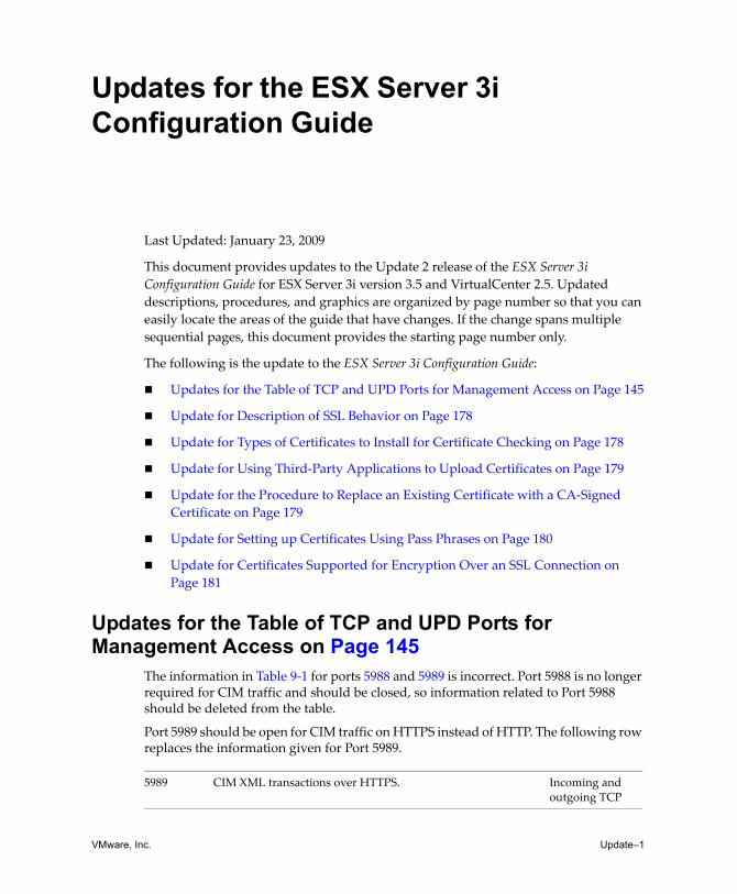
VMware, Inc. Update–1
Updates for the ESX Server 3i Configuration Guide
Last Updated: January 23, 2009
This document provides updates to the Update 2 release of the ESX Server 3i Configuration Guide for ESX Server 3i version 3.5 and VirtualCenter 2.5. Updated descriptions, procedures, and graphics are organized by page number so that you can easily locate the areas of the guide that have changes. If the change spans multiple sequential pages, this document provides the starting page number only.
The following is the update to the ESX Server 3i Configuration Guide:
Updates for the Table of TCP and UPD Ports for Management Access on Page 145
Update for Description of SSL Behavior on Page 178
Update for Types of Certificates to Install for Certificate Checking on Page 178
Update for Using Third‐Party Applications to Upload Certificates on Page 179
Update for the Procedure to Replace an Existing Certificate with a CA‐Signed Certificate on Page 179
Update for Setting up Certificates Using Pass Phrases on Page 180
Update for Certificates Supported for Encryption Over an SSL Connection on Page 181
Updates for the Table of TCP and UPD Ports for Management Access on Page 145
The information in Table 9‐1 for ports 5988 and 5989 is incorrect. Port 5988 is no longer required for CIM traffic and should be closed, so information related to Port 5988 should be deleted from the table.
Port 5989 should be open for CIM traffic on HTTPS instead of HTTP. The following row replaces the information given for Port 5989.
5989 CIM XML transactions over HTTPS. Incoming and outgoing TCP

Updates for the ESX Server 3i Configuration Guide
Update–2 VMware, Inc.
Update for Description of SSL Behavior on Page 178The section Encryption and Security Certificates for ESX Server 3i incorrectly describes SSL behavior for ESX Server 3i and states that SSL is not enabled by default. The corrected paragraph should appear as follows:
SSL certificates are used to encrypt network traffic, but the certificate used for encryption is not verified by default. Therefore, the connection between VI Client and VirtualCenter is vulnerable to a possible man‐in‐the‐middle attack. To prevent such an attack and to fully enable the security provided by certificates in ESX Server 3i, you must enable certificate checking and install new certificates.
Update for Types of Certificates to Install for Certificate Checking on Page 178
The paragraph after the procedure To enable certificate checking describes how to receive the full benefits of certificate checking, but does not specify what type of certificates to install. The following information should be included:
To receive the full benefit of certificate checking, install new certificates that are signed by a valid internal or public CA.
Update for Using Third-Party Applications to Upload Certificates on Page 179
Below the figure Security Warning in the procedure To generate new certificates for the ESX Server 3i host, the text incorrectly refers to HTTP PUT. The paragraph should reference HTTPS PUT, as follows:
In addition to the vifs command, you can also use third‐party applications to upload certificates. Applications that support HTTPS PUT operations work with the HTTPS interface that is included with ESX Server 3i. For example, you can use SeaMonkey Composer to upload a certificate and key.
NOTE If certificate checking is not enabled and new certificates are not installed, all communications over this channel are encrypted using a self‐signed certificate.
NOTE All file transfers and other communications occur over a secure HTTPS session. The user used to authenticate the session must have the privilege Host > Config > AdvancedConfig on the host. For more information on privileges, see “About Users, Groups, Permissions, and Roles” on page 166.

VMware, Inc. Update–3
Updates for the ESX Server 3i Configuration Guide
Update for the Procedure to Replace an Existing Certificate with a CA-Signed Certificate on Page 179
The procedure To use vifs to replace the existing certificate with a CA‐signed certificate contains incorrect syntax for the commands used to replace existing certificates with CA‐signed certificates. The correct syntax appears in the following procedure:
To use vifs to replace the existing certificate with a CA-signed certificate
1 Use the vifs command to put a copy of the certificate and key files on the ESX Server. The form this command takes for the certificate and key respectively is:
vifs --server hostname --username username --put rui.crt /host/ssl_certvifs --server hostname --username username --put rui.key /host/ssl_key
2 Use the ̋ Restart Management Agentsʺ operation through the local console to make the settings take effect.
Update for Setting up Certificates Using Pass Phrases on Page 180
The section Modifying ESX Server 3i Web Proxy Settings inaccurately states that you should avoid setting up certificates using pass phrases. The section should state the following:
Do not set up certificates using pass phrases. ESX Server 3i does not support pass phrases, also known as encrypted keys. If you set up a pass phrase, ESX Server 3i processes cannot start correctly.
Update for Certificates Supported for Encryption Over an SSL Connection on Page 181
The section above the procedure To change security settings for a Web proxy service omits a note about what type of certificate is supported by ESXi for encrypting session information sent over an SSL connection. The section should include the following information:
ESXi supports only X.509 certificates to encrypt session information sent over SSL connections between server and client components.

Updates for the ESX Server 3i Configuration Guide
Update–4 VMware, Inc.