Estimation of A-type Piano Key weir rating curve and Piano Key Weirs II PKW 2013 CRC Press, Boca...
9
139 1 INTRODUCTION The concept of the Piano Key weir (PKW) is a further development of the Labyrinth weir (Tul- lis 1995, Falvey 2003). Detailed historical reviews on the evolution from the Labyrinth weir to the PKW are given by Schleiss (2011) and by Lempérière et al. (2011). Two main advantages of PKWs as compared with Labyrinth weirs are: (1) Reduced structural footprint allowing for the installation on top of gravity dams (Lempérière and Ouamane 2003); and (2) Increased dis- charge capacity, as the inclined bottom of the keys instead of the horizontal-vertical arrange- ment improves the hydraulic efficiency (Laugier et al. 2009, Anderson and Tullis 2011, 2012). Due to increased flood discharges and severe specifications of the dam safety, a large number of existing dams requires spillway rehabilitation to improve their hydraulic capacity. The PKWs are then often an interesting option (Laugier 2007, Leite Ribeiro et al. 2009, Laugier et al. 2009). Tests performed on scale models as well as numerical simulations contributed to the re- cent increase of knowledge about their hydraulic characteristics and constructive aspects. Nev- ertheless, the design of most PKW prototypes is still supported by physical modelling (Laugier 2007, Dugué et al. 2011, Erpicum et al. 2011a, Cicero et al. 2011). Lempérière and Ouamane (2003) were among the first to present systematic PKW tests of type A and B, proposing rough design criteria. Ouamane and Lempérière (2006) extended their 2003 study for different dimensionless parameters. Results highlight the relevance of the ratio between the developed crest length L and the transverse width W. Lempérière et al. (2011) Estimation of A-type Piano Key weir rating curve Michael Pfister & Anton J. Schleiss Laboratory of Hydraulic Constructions (LCH), Ecole Polytechnique Fédérale de Lausanne (EPFL), Station 18, CH - 1015 Lausanne, Switzerland ABSTRACT: The Piano Key weir (PKW) is a hydraulically attractive alternative to linear over- flow weirs, increasing the unit discharge for similar heads and spillway widths. This advantage allows operating dam reservoirs on an increased level and provides thereby an enhanced reten- tion volume. It is a result of the non-linear nature of PKWs being folded back and forth to make repeating cycles or keys. As PKWs are relatively novel structures, only few design equations are available, so that normally physical model tests of prototypes have to be conducted assuring and optimizing their hydraulic characteristics. Nevertheless, first comprehensive and systematic model test series were conducted in several laboratories. Based on such a test series, a general design equation for A-type PKWs is proposed and discussed. Considering furthermore data of other laboratory studies, the latter is validated. It turned out that main and secondary parameters exist regarding the relative effect on the rating curve. The main parameters having a significant effect on the capacity are the relative developed crest length and the relative head. The second- ary parameters of small but not negligible effect comprise the ratio of the inlet and outlet key widths, the ratio of the inlet and outlet key heights, the relative overhang lengths, and the rela- tive height of the parapet walls. Labyrinth and Piano Key Weirs II – PKW 2013 CRC Press, Boca Raton
Transcript of Estimation of A-type Piano Key weir rating curve and Piano Key Weirs II PKW 2013 CRC Press, Boca...

139
1 INTRODUCTION
The concept of the Piano Key weir (PKW) is a further development of the Labyrinth weir (Tul-lis 1995, Falvey 2003). Detailed historical reviews on the evolution from the Labyrinth weir to the PKW are given by Schleiss (2011) and by Lempérière et al. (2011). Two main advantages of PKWs as compared with Labyrinth weirs are: (1) Reduced structural footprint allowing for the installation on top of gravity dams (Lempérière and Ouamane 2003); and (2) Increased dis-charge capacity, as the inclined bottom of the keys instead of the horizontal-vertical arrange-ment improves the hydraulic efficiency (Laugier et al. 2009, Anderson and Tullis 2011, 2012).
Due to increased flood discharges and severe specifications of the dam safety, a large number of existing dams requires spillway rehabilitation to improve their hydraulic capacity. The PKWs are then often an interesting option (Laugier 2007, Leite Ribeiro et al. 2009, Laugier et al. 2009). Tests performed on scale models as well as numerical simulations contributed to the re-cent increase of knowledge about their hydraulic characteristics and constructive aspects. Nev-ertheless, the design of most PKW prototypes is still supported by physical modelling (Laugier 2007, Dugué et al. 2011, Erpicum et al. 2011a, Cicero et al. 2011).
Lempérière and Ouamane (2003) were among the first to present systematic PKW tests of type A and B, proposing rough design criteria. Ouamane and Lempérière (2006) extended their 2003 study for different dimensionless parameters. Results highlight the relevance of the ratio between the developed crest length L and the transverse width W. Lempérière et al. (2011)
Estimation of A-type Piano Key weir rating curve
Michael Pfister & Anton J. Schleiss Laboratory of Hydraulic Constructions (LCH), Ecole Polytechnique Fédérale de Lausanne (EPFL), Station 18, CH - 1015 Lausanne, Switzerland
ABSTRACT: The Piano Key weir (PKW) is a hydraulically attractive alternative to linear over-flow weirs, increasing the unit discharge for similar heads and spillway widths. This advantage allows operating dam reservoirs on an increased level and provides thereby an enhanced reten-tion volume. It is a result of the non-linear nature of PKWs being folded back and forth to make repeating cycles or keys. As PKWs are relatively novel structures, only few design equations are available, so that normally physical model tests of prototypes have to be conducted assuring and optimizing their hydraulic characteristics. Nevertheless, first comprehensive and systematic model test series were conducted in several laboratories. Based on such a test series, a general design equation for A-type PKWs is proposed and discussed. Considering furthermore data of other laboratory studies, the latter is validated. It turned out that main and secondary parameters exist regarding the relative effect on the rating curve. The main parameters having a significant effect on the capacity are the relative developed crest length and the relative head. The second-ary parameters of small but not negligible effect comprise the ratio of the inlet and outlet key widths, the ratio of the inlet and outlet key heights, the relative overhang lengths, and the rela-tive height of the parapet walls.
Labyrinth and Piano Key Weirs II – PKW 2013 CRC Press, Boca Raton
140
summarize different types of PKWs which have been studied by Hydrocoop since 1998, classi-fied according to the presence or absence of overhangs. In type A, up- and downstream over-hangs are provided. Types B and C include only up- or downstream overhangs. Although type D has inclined bottoms, it does not contain overhangs.
Although the flow over a PKW is highly three-dimensional, Erpicum et al. (2011b) present a simplified one-dimensional numerical modeling for preliminary designs with an accuracy of some 10%. The model is based on cross-section-averaged equations of mass and momentum conservation with only the upstream discharge as boundary condition. By comparing PKWs of type A and D, Anderson and Tullis (2011) confirm that the presence of the overhangs has a pos-itive effect on the PKW discharge capacity. Upstream overhangs increase the inlet flow area and wetted perimeter, which results in lower energy losses.
Kabiri-Samani and Javaheri (2012) were among the first to publish general equations to de-rive the rating curve of PKWs. They conducted extensive model tests in a 12 m long and 0.4 m wide channel, operated with specific discharges between 25 and 175 l/sm. The test program in-cluded totally 600 tests resulting in some 3000 data points. The tested PKWs included types A, B, and C, all of sharp-crested type. They investigated the PKW performance under free flow and submerged conditions, i.e. with an effect of the tailwater. The Poleni equation was taken as ref-erence, and the rating curve expressed in terms of the discharge coefficient. Leite Ribeiro et al. (2012a) performed systematic model tests in a channel of 3 m length and 0.5 m width. In total, 380 tests were conducted, considering 49 different PKW geometries of type A, with cylindrical weir crests. The specific model discharge varied between 26 and 440 l/sm. Uniquely free over-flow without submergence from the tailwater was tested. The rating curve was defined relative to a linear sharp-crested weir. The present paper focuses on these tests. Machiels et al. (2012) finally conducted systematic model tests in a 7.2 m long and 1.2 m wide flume. For each param-eter set investigated, a 0.3 m wide PKW model including 2.5 cycles was inserted into the chan-nel and charged with specific discharges between 13 and 400 l/sm. The PKWs were of broad-crested type. Again, the results are only valid for free overflow conditions. Starting with an ana-lytical approach, Machiels et al. (2012) finally gives the specific PKW discharges as the sum of the specific discharges on the downstream, the upstream, and the side wall.
The common notation (Fig. 1) as defined by Pralong et al. (2011) is applied herein, with B = streamwise length, L = developed crest length, P = vertical height, R = parapet wall height, TS = wall thickness, and W = width. Furthermore, subscript i refers to the inlet key, i.e. the key that is filled with water for a reservoir surface at the PKW crest elevation, and subscript o to the outlet key, i.e. the ‘dry’ key for the latter reservoir level. The developed crest length L is defined as L = N (Wi + Wo + 2TS + 2B) or alternatively as L = W + (2NB), with N = number of PKW cycles.
Figure 1. Common PKW notation according Pralong et al. (2011).
Labyrinth and Piano Key Weirs II – PKW 2013 CRC Press, Boca Raton

141
Mainly two approaches are common to describe the PKW discharge QP: by (1) deriving a specific discharge coefficient using the Poleni equation (Kabiri-Samani and Javaheri 2012, An-derson and Tullis 2011, Ouamane et al. 2006), or (2) comparing the PKW discharge QP with that of a linear sharp-crested weir QS (Leite Ribeiro et al. 2012a). The second option is chosen herein as it seems better physically based (Falvey 2003, Schleiss 2011). The discharge QP as measured in the model is thereby compared with the theoretical value QS of a linear sharp-crested weir of width W, both under the same H. Then, the discharge enhancement ratio r fol-lows as
S
P
Q
Qr (1)
The discharge QS over a linear sharp-crested weir serving as reference is
5.12 HgWCQ SS (2)
with CS = 0.42 as discharge coefficient for a sharp-crested weir (e.g. Hager and Schleiss 2009).
2 PHYSICAL MODEL TESTS
In the frame of the study conducted by Leite Ribeiro et al. (2012a), systematic physical model tests were carried out at the Laboratory of Hydraulic Constructions (LCH) of EPFL. A straight rectangular channel with a length of 40 m, a width of 2 m and a height of 1 m was used. The ef-fective reach including the PKWs was reduced to W = 0.5 m and of 3 m length, by inserting ver-tical parallel plates. The model was of sectional type including 1.5 PKW units (Fig. 2). To ex-clude an effect of the latter set-up on the rating curve, preliminary tests were conducted with more cycles, resulting in analogue rating curves (Leite Ribeiro et al. 2012b). Different arrange-ments with similar up- and downstream overhangs were tested, all according to type A. The thickness of the walls was constant with TS = 0.02 m, and the overflow crest shape was half-circular (cylindrical weir). Semi-circular noses were mounted below the outlet keys on the res-ervoir side. All tests were conducted for free overfall conditions, so that no backwater effect in-fluenced the rating curve.
Figure 2. PKW model flow for configurations including 1.5 cycles, view from downstream on left and in flow direction on right.
Totally, 49 different PKW configurations were analyzed, resulting in 380 data points. The parameter variation included (in absolute dimensions): 1.50 m ≤ L ≤ 3.50 m,
Labyrinth and Piano Key Weirs II – PKW 2013 CRC Press, Boca Raton

142
0.33 m ≤ B ≤ 1.00 m, 0.10 m ≤ Wi ≤ 0.20 m, 0.10 m ≤ Wo ≤ 0.20 m, 0.10 m ≤ Pi ≤ 0.28 m, 0.10 m ≤ Po ≤ 0.28 m, 0.00 m ≤ Pd ≤ 0.62 m, 0.07 m ≤ Bi ≤ 0.40 m, 0.07 m ≤ Bo ≤ 0.40 m, 0.00 m ≤ R ≤ 0.06 m, and 0.02 m ≤ H ≤ 0.27 m. The parameters Ts = 0.02 m and W = 0.50 m were kept constant. Here, H = total approach flow energy head above the PKW crest, and Pd = channel height below the PKW foot, i.e. below Pi to investigate the effect of the approach flow velocity. The bottom slopes of the inlet key (Pi ‒ R)/(Bi + Bb) and of the outlet key (Po ‒ R)/(Bo + Bb) were between 0.34 and 0.84. The model discharge was varied between 0.013 m3/s ≤ QP ≤ 0.220 m3/s. Expressed in relative terms, the parameter variation included 3.0 ≤ L/W ≤ 7.0, 0.1 ≤ H/Pi ≤ 2.8, 1.5 ≤ B/Pi ≤ 4.6, 0.7 ≤ Pi/Po ≤ 1.4, 0.2 ≤ Bi/B = Bo/B ≤ 0.4, and 0.5 ≤ Wi/Wo ≤ 2.0. The values QP were measured with a magnetic-inductive flow meter, and H using a point gauge in a lateral and stagnant region. Values H < 0.05 m and H > 0.5(Pi + Pd) were not considered for the data analysis, as they might be influenced by scale effects or by the approach flow velocity.
3 RESULTS
3.1 Main parameters
The developed crest length L per linear weir width W is significant to describe the discharge ca-pacity of a PKW. Herein, these parameters are expressed as (L ‒ W)/W to account for the rela-tive capacity increase as compared to a linear sharp-crested weir. Accordingly, if L = W, then (L ‒ W)/W = 0, so that no capacity increase as compared to the latter is observed. Furthermore, the parameter Pi/H is known to be relevant for Labyrinth weirs (Tullis 1995), and also signifi-cantly affects the PKW efficiency. The data analysis conducted by Leite Ribeiro et al. (2012a) finally let to the principal normalization
9.0
WH
PWL i (3)
Figure 3a shows the values r derived from measurements versus δ, including data of Leite Ribeiro et al. (2012a) and some data of Machiels et al. (2012). Note that the data of Machiels et al. (2012) with a bottom slope (Pi ‒ R)/(Bi + Bb) > 0.7 were not collapsing with the proposed normalization, so that these were ignored and the application of Eq. (3) accordingly limited. Nevertheless, it can be seen that the data according to the limitations of the physical modeling essentially collapse, supporting the relevance of δ. The data trend is described with a linear function as (Leite Ribeiro et al. 2012a)
24.01r (4)
The coefficient of determination between the measured values and the prediction according to Eq. (4) is R2 = 0.964 for the data of Leite Ribeiro et al. (2012a) and R2 = 0.975 for those of Machiels et al. (2012). The constant “1” in Eq. (4) assures equality with the sharp-crested weir (r = 1 for δ = 0), and the term 0.24δ stands for the efficiency increase generated by the PKW if δ > 0.
3.2 Secondary parameters
It is known from several PKW model studies that some geometrical ratios, which are not in-cluded in the pragmatic approach according to Eq. (4), slightly increase or decrease the dis-charge efficiency for similar heads. These ratios were not addressed in Eq. (4) and are specified herein, by introducing four correction factors. The latter are equivalent to individual factors be-tween 0.92 and 1.20, for the geometries tested by Leite Ribeiro et al. (2012a). The individual correction factors are defined as given below, namely for the ratio between inlet and outlet key width as
Labyrinth and Piano Key Weirs II – PKW 2013 CRC Press, Boca Raton
143
05.0
o
i
W
Ww (5)
for the ratio between outlet and inlet key height as
25.0
i
o
P
Pp (6)
for the ratio between key overhangs to the base length as
50.0
30.0
B
BBb io (7)
and for the relative parapet wall height as
00.2
1
o
o
P
Ra (8)
To include the secondary parameters, Eq. (4) is completed with all correction factors, resulting in the comprehensive expression
wpbar 24.01 (9)
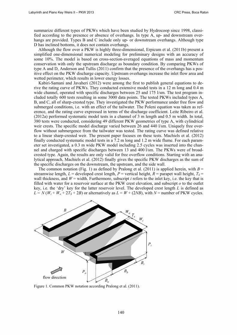
For Eq. (9), the same range of validity applies as for Eq. (4) which is mentioned in chapter 2. Figure 3b shows the measured values r, normalized with δ(wpba). The data analysis indicated a slightly better performance of Eq. (9) as compared to Eq. (4). Particularly, the number of outli-ers was reduced. The coefficient of determination between the measured values and the predic-tion according to Eq. (9) is R2 = 0.976 for Leite Ribeiro et al. (2012a) and R2 = 0.975 for Ma-chiels et al. (2012).
(a) (b) Figure 3. Values r derived from measurements versus (a) δ, compared with prediction following Eq. (4), and (b) δ(wpba), compared with prediction following Eq. (9).
Labyrinth and Piano Key Weirs II – PKW 2013 CRC Press, Boca Raton

144
4 COMPARISON (CASE STUDY)
A exemplarily comparison of the so far available design equations related to rating curves of PKWs (Kabiri-Samani and Javaheri 2012, Leite Ribeiro et al. 2012a, and Machiels et al. 2012) is given by Pfister and Schleiss (2013) and reproduced herein. An explicit comparison between the prediction according to Leite Ribeiro et al. (2012a) and the data of Machiels et al. (2012) is included in Fig. 3, as these individual values were available. As for the equation of Kabiri-Samani and Javaheri (2012), no measurement data are accessible, so that an implicit comparison based on a virtual site is necessary.
Such a comparison in the frame of a virtual prototype has to be defined in accordance with the limits of the individual studies as given in Table 1, as far as possible. The chosen prototype remains somehow arbitrary in terms of its characteristics, limiting the informative value of the comparison.
The following virtual site is used as base of the comparison, including 1 A Roller Compacted Concrete (RCC) gravity dam with a W = 100 m wide chute spillway
on its downstream face, a dam height of Pd = 30 m below the PKW foundation, free over-fall conditions at the weir without tailwater submergence, and ignoring the effect of the distal weir ends.
2 A design discharge of QD = 2500 m3/s, according to a specific discharge of 25 m2/s (as common on stepped spillways, Pfister et al. 2006).
3 A symmetrical A-type PKW, mounted at the dam crest as unregulated control structure, with B = 8.00 m as total streamwise length, P = Pi = Po = 5.00 m as vertical height, TS = 0.35 m as wall thickness, R = 0 m (without parapet walls), Wi = 1.80 m as inlet key width, Wo = 1.50 m as outlet key width, and Bi = Bo = 2.00 m as overhang lengths (Fig. 1). The crest shape remains undefined.
The following characteristics follow from the above chosen PKW geometry: cycle width
Wu = Wi + Wo + 2TS = 4.00 m, number of cycles N = W/Wu = 25, developed crest length L = W + (2NB) = 500 m, L/W = 5.00, B/P = 1.60, Wi/Wo = 1.20, Bi/B = Bo/B = 0.25, and Si = So = 0.83. The latter does not respect the limitations of the prediction proposed by Leite Ri-beiro et al. (2012a), requiring Si = So < 0.70. The related data analysis showed that their equa-tion then slightly overestimates the discharge capacity. To derive the discharge capacity, fur-thermore only water heads between 0 to 6 m were considered.
Given that the three compared equations base on model studies using different crest shapes, their effect has to be taken into account. Kabiri-Samani and Javaheri (2012) used a sharp-crested weir, Leite Ribeiro et al. (2012a) a cylindrical weir crest, and Machiels et al. (2012) a broad-crested weir. The discharges were thus first computed according to the proposed equation of the aforementioned studies, and then normalized to the broad-crested weir. The discharge co-efficients Cd were derived with Hager and Schwalt (1994) for the broad-crested weir, where Cd tends from Cd = 0.33 for
H < 0.2 m to Cd = 0.42 for H > 1 m. Hager and Schleiss (2009) for the sharp-crested weir, where Cd = 0.42 for all H. Castro-Orgaz (2012) for cylindrical weir crests if H < 0.5 m (Cd = 0.54 at H = 0.5 m),
then linearly approaching Cd = 0.42 at H = 4.4 m as observed by Ramamurthy and Vo (1993), and finally Cd = 0.42 for all H > 4.4 m.
The resulting rating curves for the three herein compared design equations are shown in Fig. 4a, also respecting their application limits in terms of H/P. As can be seen, the rating curves of the three PKW studies are similar. In general, the empiric equation of Kabiri-Samani and Ja-vaheri (2012) predicts the highest discharge capacity. Additionally, the rating curve of a linear standard crest profile (ogee) is shown in Fig. 4a, derived from Vischer and Hager (1999) con-sidering a design head of HD = 5.00 m for QD.
All PKW curves start at typically H/P = 0.1 according to H = 0.50 m because of the lower model limitation to avoid scale effects. The error following from scale effects is probably small if applying the equations also in the reach H < 0.50 m (Pfister et al. 2013). For a large head of H = 5.00 m (H/P = 1) (according to the design head), the predictions of Leite Ribeiro et al. (2012a) and Machiels et al. (2012) result in QP = 4041 m3/s and QP = 3594 m3/s, respectively. For the design discharge of QD = 2500 m3/s, the equation of Leite Ribeiro et al. (2012a) gives
Labyrinth and Piano Key Weirs II – PKW 2013 CRC Press, Boca Raton

145
H = 3.36 m and Machiels et al. (2012) gives H = 3.38 m (both at around H/P = 0.67). Interesting is the comparison of the PKW discharge capacity with that of the ogee. For the latter, the head H = 5.00 m for QD = 2500 m3/s according to its design criterion. The hydraulic head of the ogee is thus 148% of that of the PKW, for an identical discharge. The related absolute head differ-ence is around 1.63 m. The dam height might thus be reduced by this difference, resulting in lower construction cost, or the height difference is available to generate additional storage vol-ume.
Figure 4b shows the discharge ratio η = QP/QO versus H, with QO = ogee discharge. As visi-ble, the efficiency of PKWs is particularly high for small heads. Then, the developed length L is fully active, similar to a very long linear sharp crested weir. For a head of H = 1.00 m (H/P = 0.2), a PKW spills around 3.5 to 4.5 times the discharge of an ogee, dependent on the chosen equations to derive the PKW discharge. Note that the ratio L/W = 5.00 herein, a value slightly exceeding the aforementioned capacity increase. For higher discharges, the flow inter-action in the PKW crest wedges and corners (in plan view) becomes dominant, so that the ca-pacity decreases and finally approaches that of an ogee (η → 1). For heads H > 3.0 m (H/P > 0.6) a discharge ratio of η ≤ 2 occurs. Even though these heads are hydraulically still ef-ficient at PKWs, they might be less interesting from an economical point of view as compared to the construction cost of an ogee crest.
(a)
(b) Figure 4. Comparisons of (a) rating curves for PKW and ogee crest weirs, (b) relative discharge capacity of PKW with ogee as reference (ogee capacity as η = 1).
Labyrinth and Piano Key Weirs II – PKW 2013 CRC Press, Boca Raton
146
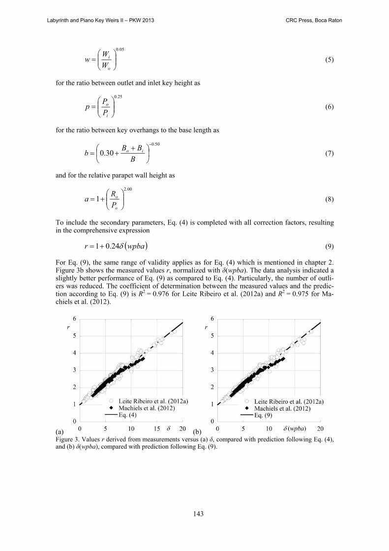
Table 1. Application ranges of listed design equations. L/W H/P Wi/Wo B/P Bi/B, Bo/BKabiri-Samani and Ja-vaheri (2012) 2.5 to 7.0 0.1 to 0.6 0.33 to 1.22 1.0 to 2.5 0.00 to 0.26
Leite Ribeiro et al. (2012a) 3.0 to 7.0 0.1 to 2.8 0.50 to 2.00 1.5 to 4.6 0.20 to 0.40
Machiels et al. (2012) 4.2 to 5.0 0.1 to 5.0 0.50 to 2.00 1.0 to 6.0 0.29 to 0.33
5 SUMMARY
Piano Key weirs are frequently included in spillways these days because of their hydraulic effi-ciency. The latter was commonly validated and optimized using physical models. Nevertheless, some basic research projects were recently conducted, providing first general design equations related to the head-discharge function of PKWs. Herein, the proposal of Leite Ribeiro et al. (2012a) is presented. The latter involves main parameters, as the relative crest length and the relative weir height, which significantly affect the rating curve; and secondary geometrical pa-rameters with have a small but non-negligible effect. Besides hydraulic aspects as discussed by Leite Ribeiro et al. (2012a), a constructional and economic consideration is given by Machiels et al. (2012).
PKWs are particularly efficient in conveying large specific discharges under small heads if compared to ogee crests. An exemplarily comparison of these two unregulated spillway inlets is given and discussed. Furthermore, the herein compared equations to predict the PKW rating curves give similar, but not identical results. The difference might be explained with the differ-ent crest types of the physical models, which were used to derive the design equations.
6 REFERENCES
Anderson, R.M., Tullis, B. 2011. Influence of Piano Key Weir geometry on discharge. Proc. Intl. Conf. Labyrinth and Piano Key Weirs Liège B, 75-80. CRC Press, Boca Raton, FL.
Anderson, R.M., Tullis, B. 2012. Comparison of Piano Key and rectangular Labyrinth Weir hydraulics. J. Hydraulic Eng., 138(4), 358-361.
Castro-Orgaz, O. 2012. Discussion Overflow characteristics of circular-crested weirs. J. Hydraulic Res. 50(2): 241–243.
Cicero, G.M., Menon, J.M., Luck, M., Pinchard, T. 2011. Experimental study of side and scale ef-fects on hydraulic performances of a Piano Key Weir. Proc. Intl. Conf. Labyrinth and Piano Key Weirs Li-ège B, 167-172. CRC Press, Boca Raton, FL.
Dugué, V., Hachem, F., Boillat, J.-L., Nagel, V., Roca, J.-P., Laugier, F. 2011. PKWeir and flap gate spillway for the Gage II Dam. Proc. Intl. Conf. Labyrinth and Piano Key Weirs Liège B, 35-42. CRC Press, Boca Raton, FL.
Erpicum, S., Nagel, V., Laugier, F. 2011a. Piano Key Weir design of Raviege dam. Proc. Intl. Conf. Lab-yrinth and Piano Key Weirs Liège B, 43-50, CRC Press, Boca Raton, FL.
Erpicum, S., Machiels, O., Archambeau, P. Dewals, B., Pirotton, M. 2011b. 1D numerical modeling of the flow over a Piano Key Weir. Proc. Intl. Conf. Labyrinth and Piano Key Weirs Liège B, 151-158. CRC Press, Boca Raton, FL.
Falvey, H.T. 2003. Hydraulic design of labyrinth weirs. ASCE Press, Reston VA. Hager, W.H., Schleiss, A.J. 2009. Constructions hydrauliques, Ecoulements stationnaires. Traité de Gé-
nie Civil, Vol. 15, Presses Polytechniques et Universitaires Romandes, Lausanne, Switzerland. Hager, W.H., Schwalt, M. 1994. Broad-crested weir. J. Irrigation and Drainage Engng 120(1): 13-26. Kabiri-Samani, A., Javaheri, A. 2012. Discharge coefficient for free and submerged flow over Piano Key
weirs. J. Hydraulic Res., 50(1), 114-120. Laugier, F. 2007. Design and construction of the first Piano Key Weir (PKW) spillway at the Goulours
dam. Intl. J. Hydropower and Dams, 13(5), 94-101. Laugier, F., Lochu, A., Gille, C., Leite Ribeiro, M., Boillat, J-L. 2009. Design and construction of a laby-
rinth PKW spillway at St-Marc Dam, France. Intl. J. Hydropower and Dams, 15(5), 100-107. Leite Ribeiro, M., Bieri, M., Boillat, J-L., Schleiss, A., Delorme, F., Laugier, F. 2009. Hydraulic capacity
improvement of existing spillways – Design of piano key weirs. 23rd ICOLD Congress. Q90, R43, 25-29. Brasilia, Brazil.
Leite Ribeiro, M., Pfister, M., Schleiss, A.J., Boillat, J.-L. 2012a. Hydraulic design of A-type Piano Key weirs. J. Hydraulic Res. 50(4): 400–408.
Labyrinth and Piano Key Weirs II – PKW 2013 CRC Press, Boca Raton
147
Leite Ribeiro, M., Pfister, M., Boillat, J.-L., Schleiss, A.J., Laugier, F. 2012b. Piano Key weirs as effi-cient spillway structure. 24th ICOLD Congress, Kyoto (J), Q.94 – R.13.
Lempérière, F., Ouamane, A. 2003. The Piano Keys weir: a new cost-effective solution for spillways. Intl. J. Hydropower and Dams, 10(5), 144-149.
Lempérière, F., Vigny, J.P., Ouamane, A. 2011. General comments on Labyrinth and Piano Key weirs: The past and present. Proc. Intl. Conf. Labyrinth and Piano Key Weirs Liège B, 17-24. CRC Press, Boca Raton, FL.
Machiels, O., Pirotton, M., Archambeau, P., Dewals, B., Erpicum, S. 2013. Experimental parametric study and design of Piano Key weirs. J. Hydraulic Res. in press.
Ouamane, A., Lempérière, F. 2006. Design of a new economic shape of weir. Proc. Intl. Symp. Dams in the Societies of the 21st Century, 463-470. Barcelona, Spain.
Pfister, M., Battisacco, E., De Cesare, G., Schleiss, A.J. 2013. Scale effects related to the rating curve of cylindrically crested Piano Key weirs. Proc. Intl. Conf. Labyrinth and Piano Key Weirs Chatou F, CRC Press, Boca Raton.
Pfister, M., Schleiss, A.J. 2013. Comparison of hydraulic design equations for A-type Piano Key weirs. Proc. Intl. Conf. Water Storage and Hydropower Development for Africa (Africa 2013), Addis Ababa (Ethiopia), CD 13.05.
Pfister, M., Hager, W.H., Minor, H.-E. 2006. Bottom aeration of stepped spillways. J. Hydraulic Eng., 132(8), 850-853.
Pralong, J., Vermeulen, J., Blancher, B., Laugier, F., Erpicum, S., Machiels, O., Pirotton, M., Boillat, J.L., Leite Ribeiro, M., Schleiss, A.J. 2011. A naming convention for the Piano Key weirs geometrical parameters. Proc. Intl. Conf. Labyrinth and Piano Key Weirs Liège B, 271-278. CRC Press, Boca Ra-ton, FL.
Ramamurthy, A.R., Vo, N.D. 1993. Characteristics of circular-crested weir. J. Hydraulic Eng. 119(9), 1055-1062.
Schleiss, A.J. 2011. From labyrinth to piano key weirs: A historical review. Proc. Intl. Conf. Labyrinth and Piano Key Weirs Liège B, 3-15. CRC Press, Boca Raton FL.
Tullis, J.P. 1995. Design of Labyrinths spillways. J. Hydraulic Eng. 121(3), 247-255. Vischer, D., Hager, W.H. 1999. Dam Hydraulics. Wiley, Chichester UK. Acknowledgments The authors thank Mr Olivier Le Doucen (e-dric Engineering, Lausanne) for having conducted the model tests in the frame of his Master Thesis at EPFL. The excellent support of Dr Jean-Louis Boillat (formerly at LCH, EPFL) and Dr Marcelo Leite Ribeiro (now at Stucky, Lausanne; formerly at LCH, EPFL) is also kindly acknowledged.
Labyrinth and Piano Key Weirs II – PKW 2013 CRC Press, Boca Raton