ERDC/CRREL TR-15-15 'Naval Arctic Research Laboratory ... · solves the nation’s toughest...
54
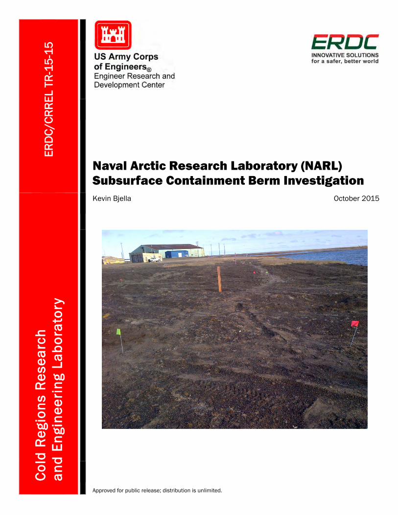
ERDC/CRREL TR-15-15 Naval Arctic Research Laboratory (NARL) Subsurface Containment Berm Investigation Cold Regions Research and Engineering Laboratory Kevin Bjella October 2015 Approved for public release; distribution is unlimited.
Transcript of ERDC/CRREL TR-15-15 'Naval Arctic Research Laboratory ... · solves the nation’s toughest...
ERD
C/CR
REL
TR-1
5-15
Naval Arctic Research Laboratory (NARL) Subsurface Containment Berm Investigation
Cold
Reg
ions
Res
earc
h
and
Engi
neer
ing
Labo
rato
ry
Kevin Bjella October 2015
Approved for public release; distribution is unlimited.

The U.S. Army Engineer Research and Development Center (ERDC) solves the nation’s toughest engineering and environmental challenges. ERDC develops innovative solutions in civil and military engineering, geospatial sciences, water resources, and environmental sciences for the Army, the Department of Defense, civilian agencies, and our nation’s public good. Find out more at www.erdc.usace.army.mil.
To search for other technical reports published by ERDC, visit the ERDC online library at http://acwc.sdp.sirsi.net/client/default.

ERDC/CRREL TR-15-15 October 2015
Naval Arctic Research Laboratory (NARL) Subsurface Containment Berm Investigation
Kevin Bjella U.S. Army Engineer Research and Development Center (ERDC) Cold Regions Research and Engineering Laboratory (CRREL) Alaska Research Office Building 4070, 9th Street Fort Wainwright, AK 99703
Final Report
Approved for public release; distribution is unlimited.
Prepared for Naval Facilities Engineering Command (NAVFAC) Northwest 1101 Tautog Circle Silverdale, WA 98315
under Military Interdepartmental Purchase Request N6247314MPT0006, “2014 Barrow Containment Berm Evaluation”

ERDC/CRREL TR-15-15 ii
Abstract
The former Navy Arctic Research Laboratory Airstrip Site in Barrow, Alaska, has a history of fuel spills. Various methods have been used to re-mediate the site, including installing a subsurface containment berm and associated recovery trenches. The containment berm was designed to cre-ate a raised permafrost feature that effectively prevents free product mi-grating from the upstream side to the downstream side.
This study focused on using non-intrusive ground-penetrating-radar (GPR) techniques coupled with ground probing and desktop thermal anal-yses to assess if these methods could help to determine whether the con-tainment berm is functioning as designed (i.e., effectively decreasing ac-tive-layer thickness and raising the permafrost table).
The results demonstrate that these GPR methods were useful for this study and that the berm is effectively raising the permafrost table along the survey transects explored.

ERDC/CRREL TR-15-15 iii
Contents Abstract .......................................................................................................................................................... ii
Illustrations .................................................................................................................................................... iv
Preface ............................................................................................................................................................. v
Acronyms and Abbreviations ...................................................................................................................... vi
1 Introduction ............................................................................................................................................ 1
2 Background ............................................................................................................................................ 2 2.1 Containment berm .......................................................................................................... 2 2.2 Ground-penetrating radar............................................................................................... 4
3 Method .................................................................................................................................................... 7 3.1 GPR surveying ................................................................................................................. 8 3.2 Frost-depth probing......................................................................................................... 8 3.3 Post-processing ............................................................................................................... 9
4 Discussion ............................................................................................................................................ 10 4.1 GPR reflection waveforms (water vs. ice) .................................................................... 10 4.2 Probing results .............................................................................................................. 12 4.3 Missing section of the containment berm ................................................................... 13 4.4 Thermal analysis ........................................................................................................... 14
5 Results .................................................................................................................................................. 23
6 Conclusions .......................................................................................................................................... 25
References ................................................................................................................................................... 26
Appendix A: GPS Transect Coordinates .................................................................................................. 27
Appendix B: All Transects .......................................................................................................................... 28
Report Documentation Page

ERDC/CRREL TR-15-15 iv
Illustrations
Figures
1 A plan view of the airstrip area, detailing the locations of the containment berm and recovery trenches ................................................................................................................... 2
2 The design cross section of the containment berm .................................................................. 3 3 The 2001 as-built containment berm extension and monitoring wells .................................. 5 4 A site plan with systematic and Monitoring Well Transect (MWT) locations .......................... 6 5 An example GPR reflection showing waveform signature ...................................................... 11 6 A plan map of the 67 m berm extension, constructed in 2000, shown as an
angle at the location where the GPR survey found insulation/plywood missing ................ 14 7 A GPR image interpretation of the MWT. The MWT from AS-WP-101 to AS-WP-10
ended at the beginning of the sands of Imikpuk Lake shoreline. The length is approximately 50 m. This transect was not part of the systematic transects. The surface has been normalized to simulate the drop in surface elevation ............................. 17
8 A GPR image interpretation of systematic transect L6. The left is near Dew Line Road, and the right stops short of the shoreline of Imikpuk Lake. The length is 50 m ............................................................................................................................................... 17
9 A GPR image interpretation of systematic transect L7. The left is near Dew Line Road, and the right stops short of the shoreline of Imikpuk Lake. The length is 50 m ............................................................................................................................................... 18
10 A GPR image interpretation of systematic transect L8. The left is near Dew Line Road, and the right stops short of the shoreline of Imikpuk Lake. The length is 40 m ............................................................................................................................................... 18
11 A GPR image interpretation of systematic transect L11. The left is just north of Dew Line Road, and the right stops short of the shoreline of Imikpuk Lake. The length is 40 m ............................................................................................................................... 19
12 A GPR image interpretation of systematic transect L12. The left is just north of Dew Line Road, and the right stops short of the shoreline of Imikpuk Lake. The length is 40 m ............................................................................................................................... 19
13 A GPR image interpretation of systematic transect L13. The left is just north of Dew Line Road, and the right stops short of the shoreline of Imikpuk Lake. The length is 40 m ............................................................................................................................... 20
14 A GPR image interpretation of systematic transect L22. The left is just north of Dew Line Road and near the southwest corner of the Navy Hangar, and the right stops at the edge of the road embankment. The length is 20 m .......................................... 20
15 A GPR image interpretation of transect L01 along the axis of the containment berm. The left starts at L1 with the insulation/plywood beginning at approximately 10 m. A break in the insulation/plywood is clearly visible starting at about 46 m and ending at about 55 m ................................................................................ 21
Tables
1 Swing-tie measurements to selected 0 m start points ............................................................. 8 2 Depth (m) to frost and top of insulation/plywood along transect lines L7 through
L13 ................................................................................................................................................. 12

ERDC/CRREL TR-15-15 v
Preface
This study was conducted for Naval Facilities Engineering Command Northwest (NAVFAC NW) under Military Interdepartmental Purchase Re-quest N6247314MPT0006, “2014 Barrow Containment Berm Evaluation.” The technical monitor was Kendra Leibman, NAVFAC NW.
The work was performed by the Kevin Bjella (Force Projection and Sus-tainment Branch, Dr. Loren Wehmeyer, Acting Chief), U.S. Army Engineer Research and Development Center, Cold Regions Research and Engineer-ing Laboratory (ERDC-CRREL). At the time of publication, Dr. Loren Wehmeyer was Chief of the Research and Engineering Division. The Dep-uty Director of ERDC-CRREL was Dr. Lance Hansen, and the Director was Dr. Robert Davis.
The author gratefully acknowledges U.S. Navy personnel for their support during the fieldwork of this project. The author would also like to thank Jason Weale and Quentin Gehring (CRREL) for reviewing this report.
For more information, contact Kevin Bjella 907-361-5171 [email protected]
COL Bryan S. Green was the Acting Commander of ERDC, and Dr. Jeffery P. Holland was the Director.

ERDC/CRREL TR-15-15 vi
Acronyms and Abbreviations
AFDD Air Freezing Degree-Days
ATDD Air Thawing Degree-Days
CRREL Cold Regions Research and Engineering Laboratory
ERDC U.S. Army Engineer Research and Development Center
FWENC Foster Wheeler Environmental Corporation
GPR Ground-Penetrating Radar
GPS Global Positioning System
HDPE High-Density Polyethylene
MAAT Mean Annual Air Temperature
MWT Monitoring-Well Transect
NARL Naval Arctic Research Laboratory
NAVFAC Naval Facilities Engineering Command
NW Northwest
SE Southeast
SW Southwest
UTM Universal Transverse Mercator
XPS Extruded Polystyrene
WGS World Geodetic System

ERDC/CRREL TR-15-15 1
1 Introduction
In 1996, under contract with the Navy, Foster Wheeler Environmental Corporation (FWENC) constructed a subsurface containment berm at the airfield of the Naval Arctic Research Laboratory (NARL), in Barrow, Alaska. This berm was designed to stop the migration of fuel oil from en-tering Imikpuk Lake, a drinking-water source, and to collect product in subsurface recovery trenches. As part of the U.S. Navy’s ongoing monitor-ing and assessment strategy, the U.S. Army Cold Regions Research and Engineering Facility (CRREL) Alaska Research Office conducted ground-penetrating radar (GPR) surveys in August 2014 to determine if a non-in-vasive method could help to determine whether the containment berm is functioning as designed. This report describes the fieldwork and the re-sults and makes recommendations for further investigation.

ERDC/CRREL TR-15-15 2
2 Background
Over its history, NARL has cleaned up on-site fuel spills to various degrees and with various methods. One effort in particular, the installation of a subsurface containment berm and associated recovery trenches, was de-signed to exploit the cold conditions of Barrow and to create a raised per-mafrost feature that effectively prevents free product on the airfield from migrating into Imikpuk Lake (Figure 1).
Figure 1. A plan view of the airstrip area, detailing the locations of the containment berm and recovery trenches (Naval Facilities Engineering Command Northwest [NAVFAC] 2014).
2.1 Containment berm
The containment berm was designed to raise the elevation of the perma-frost table, also known as the bottom of the seasonal active layer in the continuous permafrost zone, along a line separating Imikpuk Lake from the airstrip area and to prevent free product from entering the lake. Long, cold winters and short, cool summers in Barrow provide a temperature re-gime that is conducive to manipulating the permafrost-table elevation via the use of thermal resistance or other means.

ERDC/CRREL TR-15-15 3
In the case of the berm, this was accomplished by installing two, 5 cm thick and 3.7 m wide layers of extruded polystyrene (XPS) board insula-tion at approximately 1.0 m below the ground surface for the length of the berm. The XPS was covered with 2.0 cm thick marine-grade plywood and a 0.6 m layer of gravel for protection. Figure 2 provides a schematic of the containment-berm cross section. In addition to the containment berm, product recovery trenches were installed upstream and parallel to the berm. These trenches were designed to collect free product from past spills upstream of the berm as it flows towards the lake. FWENC deactivated the recovery trenches in 2002 after free-product quantities recovered by the system diminished to a levels where it was no longer practicable to con-tinue operating the system; characterizing performance of these trenches was not a part of the scope of this study.
Figure 2. The design cross section of the containment berm (NAVFAC 1998).
Soil conditions at this location generally consist of site fills derived from local marine and non-marine gravel sources in the area; typical gravel-sized particles are less than 2.0 cm in diameter and include minor amounts of fine sand, silt, and clay. Typically, in the Barrow area, site fills have generally been placed directly over the natural tundra surface with-out clearing or removing natural vegetation.

ERDC/CRREL TR-15-15 4
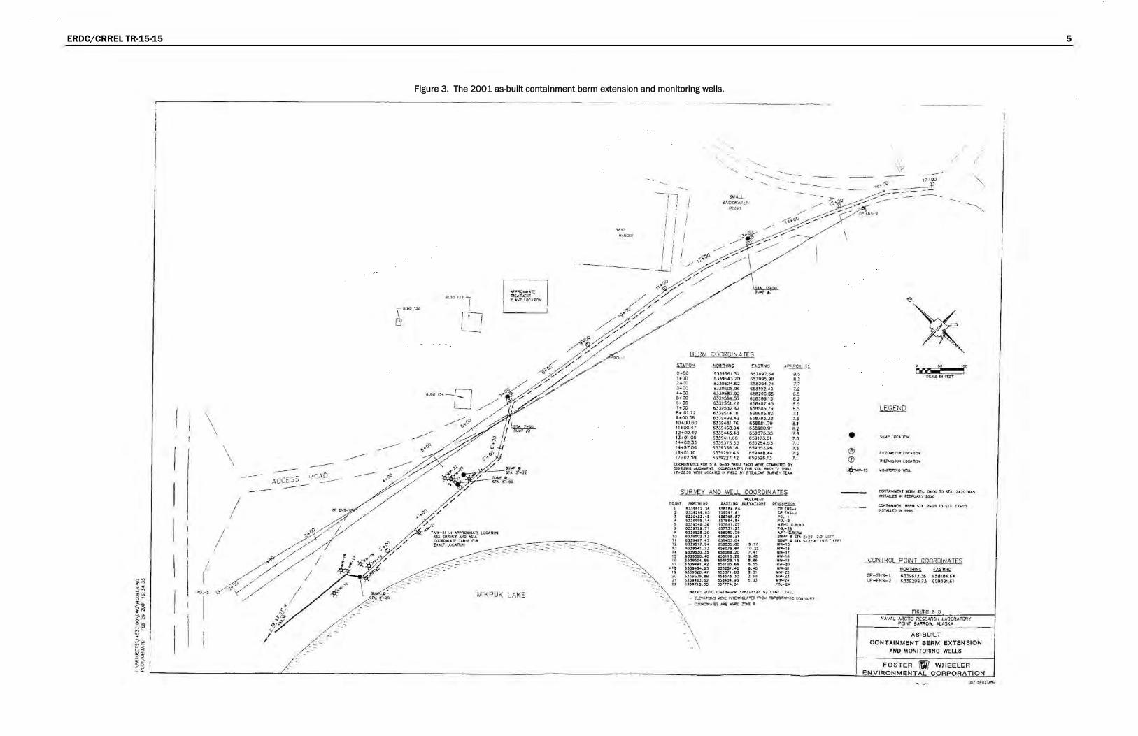
The planned location and alignment of the berm ran east to west and ex-tended for 515 m between station 0+00 and station 17+00 (Figure 3). The area between stations 7+00 and 17+00 contained no free product, so this section was constructed as originally planned. Free product was present between the planned alignment and the lake from station 3+00 to station 6+00. As such, the as-built location of the berm was moved 53 m toward the lake to prevent subsurface product migration into the lake (NAVFAC 1998). In 2000, under contract with the Navy, FWENC extended the berm 67 m to provide increased protection to the lake and groundwater (NAVFAC 2001). Figure 3 shows both the as-built location of the original berm and the later extension in 2000.
2.2 Ground-penetrating radar
GPR is a geophysical method that transmits high-frequency radio waves (10 MHz to 4 GHz) into the subsurface and records the reflections of these waves from subsurface discontinuities. The velocity of radar waves changes due to the differing dielectric permittivity from one substance to another. This contrast results in visible electrical phase changes for inter-pretation. In permafrost soils, the physical phase change between water and ice provides a detectable dielectric contrast. The thawed active layer consists of soil and water while the still-frozen layer at depth consists of soil and ice, or possibly only ice. Seasonal thaw depth in permafrost ter-rain is commonly associated with segregation ice at the bottom of the ac-tive layer, also referred to as the transition zone (Shur et al. 2005; Bjella 2013); and this zone is highly reflective to the radar waves. Additionally, water that often pools on the top of the permafrost table can produce high reflections that aid in measuring seasonal thaw depth and in identifying locations of pooling water. Although both conditions produce high reflec-tions, they produce distinctly different waveform signal responses.
ERDC/CRREL TR-15-15 5
Figure 3. The 2001 as-built containment berm extension and monitoring wells.
\
......... ----I
-------------·- -·----·--·-- -·-- .
iROC lJ.) l
rtt L_j
API'I!OX .. Al'! TlttAT\4CN't ?tAS"T ;.ocA nOH
. .... :: -:::
........ _ ---.-,
: SMALL 9~CKWATER
PONO
i I I
I I
' I
I i I I
: I ' i
I I I I
Bt:.'lM COOROINA TE S
mi!ll!i ~ ~ ~ 0+00 ~))9661.32 657897.64 9 .5 : + 00 S3J96 43.20 6!>7995.98 8. 2 2 +-00 6339624.62 S5!094.2<l 77 )+00 SJJ9605.96 658\n,4g 7.2 4•00 6.lS9587.92 658290.65 6.~ s ... oo 6JJ9569.57 6583&9.15 6.2 O•oo 6339551.22 65848'7.4.$ 5. 5 7 +00 633i5J2.87 658585. 79 6.5 8 .... 01.?2 6339514.18 656685.80 7.1 9•00 . .36 6JJ9499.42 658783.32 7.6 10+00.60 6339<481.7f; 658881.79 S.1 11+00.4 7 63.39463.04 658980.91 8.2 12+00.49 63.)9~48 659078.~ 7.8 l J-4-01.00 6lJ9411.66 6~9l7l.01 7.0 :4+C0.3l 6J)9.l7J,J.) 6 59254.SJ 7,0 1-4+97.06 6J393J6.16 55935).95 7.~ 16 +0!.1 0 6))9292.63 859448. 44 7.5 17+02.59 6)39227.32 659526.!J 7.1
COOftCNAl'CS fC;lR $TA. 0+00 TH.RU 7+00 wtR( CQt.IPUT(;) 8Y !l«ii'11Z"t1C AUCHI.tEftf. CO'.lftOII'IA TES rOA: STA. !1+01.n l'!«U l't•02.$t 'lw(R( l OCAftC :-1 nuD !tY BTSjlCUf" SUA~Y ~-
SURVEY AND V!El l COORDINA TES
~~ \ UJtii2. >S 2 ll.li2U. tl J t.l3U5J . • 5 4 UJUtS .1 • ~ IJ.JU41 . J6 & t .JJtT2t. 7 1 9 4J..)t526. 20 10 UltS02. 13 1 t &lJ94 t7. • J 12 4.1.}9$11 , ,. IJ SlJtS4L7) ' ' U3t)30, , 15 63.39520.40 16 SlJt504 . e& ,., 6 339491 . 47
• :s UJt48".2J 1t t.l3SI520. 4 7 20 &3.l9Sot.ee 21 63Jt4a..l.62 U 6lJ9718 . S5
-.(UH(,AO UUlJjj; ~
45SU4 , 14 6Ul9, . 11 Ua7,.11 . ~7 SS7184.&4 6576$1. 07 137731.1.7 451(!8Q.08 U~9fl . 21
~~·03 .04 SStO.l). OO 9 . 17 &Sto7t .n 10. 22 asaoea. 2o '·"' lSt118.1& ' ·"· 6SIII25. Hl S . &l U.!110S.6& &.SS asazst .•o a.•t> 1.5&371 .03 a . Jt auna .lo 2.t o asa.o4.t8 e.oJ 55 7174.&1
QCJ:81ell2:! (P (NS-1 CP tH.'i-2 ~()(. .. 1 POI.- :z ~.EWQ_C..BtJtll PQ..-18 A..P1- C.80lw StM" 0 STA. 2•20 2..2' l En' SUIR" 0 SlA S• 22.4 l t .$' UfT .ww-15 U'W•16 ...... ,, WW-16 NW-I i vvr-20 .. ...,_a, __ ,., WW-2 l Wtfl'-14 POl-2 ..
N.ot r : ;zooo 1 hdd .. ·ork t-onclwchcl b y t.CJ.(r, t l'l~ .
~ ;·~
- EtEVAfiOti$ 't1I('P.£ t"ITERP~ 'tO .rtl:(;fo! TQPOCP~~ CO!H¢1..1-AS
- CO(»>'tmmA r(S ARt AS'PC .t~ 6
·. \ · . \ ... \
\
• ® 0
lll(lOWtll:ilt LOC.~onOH
~Eib~ISTOR l,OCArkJH
/ /
-
* .vw-·tS
C()<o!TAW-"'Dl ~ STA.. Ot.OO 1'0 SfA. 2•10 W4$ HS1AI.Ll0 IH FteRVNtY 20oO
CQtoiTAlHII!NT IQlW STA. 2•20 TO STA 17+00 IH$TAI.UJ) IN '"5
(;UN I KUL POINT COORDINATES
~ W1l!lll CP- ENS-1 6339612.35 65818<4.6• CP - ENS-2 6339299.93 659J91.61
ncURE 3- 3 NAVAl.. AACnC R(Sf.ARCH l,.ASORATORY
POINT 9ARROW. AlASKA
AS-BUILT CONTAINMENT BERM EXTENSION
AND MONITORING WELLS
FOSTER W#j WHEELER ENVIRONMENTAL CORPORATION
-. ('\ U>7tSP03 owe

ERDC/CRREL TR-15-15 6
Figure 4. A site plan with systematic and Monitoring Well Transect (MWT) locations. The systematic transect locations are in yellow; the MWT is in blue.
Select Monitoring Well Locations
Containment Berm
Recovery Trench
0 100 200 Monitoring Well GPR Transect
Systematic GPR Transects Approximate Scale (Meters)
J N
I WGS 1984 UTM Zone 4N North
NARL Subsurface Containment Berm Investigation
SITE PLAN WITH SYSTEMATIC AND MONITORING WELL TRANSECT
LOCATIONS
MARCH 2015
[I!ZJ] ERDC ~ Figure4
ERDC/CRREL TR-15-15 7
3 Method
The CRREL Alaska Research Office laid survey transects orthogonal to the berm every 15 m for the entire length and beyond the ends of the berm by as much as 15 m for a total of 36 orthogonal systematic transects. These lines ranged from 10 to 50 m length. The western-most transect was L1; the eastern-most transect was L36.
The northerly end of each transect, referred to as the 0 m mark, was used as beginning points for GPR surveys. Flags were inserted every 10 m along each transect as fiducial reference markers for accurate positioning and normalizing of the GPR data. These marks are used as a time and location reference during data collection. All orthogonal transects were surveyed in a north to south manner starting at respective 0 m marks and ending to-wards Imikpuk Lake.
We performed two longitudinal surveys in opposite directions directly over the axis of the berm for the full length and extending approximately 15 m beyond the ends of the berm. We compared the responses as a quality check of data and methods, and the responses correlated well. We com-pleted one additional transect (Monitoring Well Transect—MWT) running in a straight line from 10 m north of monitoring well AS-WP-101 adjacent to the blue treatment building and then across the road to a point 10 m past monitoring well AS-WP-10 in the tundra and to the sands of Imikpuk Lake. The ice depth was measured in AS-WP-101 at 1.4 m, and frost depth was measured adjacent to AS-WP-10 at 0.8 m. Figure 4 shows a site plan with systematic transects and the MWT.
We used frost-probe rods to ground truth the GPR surveys, pushing them down by hand from the surface to the permafrost table. In the area to the west of Dew Line Road at the northern end of the containment berm, probing was generally successful and allowed us to determine the depth to the top of the permafrost. We also used it to verify the existence of ply-wood installed during the trench construction. We attempted probing in Dew Line Road and in the area adjacent to the Navy Hangar and Treat-ment Building; however, subsurface soils were much more compacted in these areas and did not allow for probing to occur. Mapping the locations
ERDC/CRREL TR-15-15 8
of the transects was accomplished by surveying each transect start and end locations with a hand-held Global Positioning System (GPS) (Appendix A). Three of the 0 m start points at transects L13, L17, and L23 were measured with swing ties to adjacent building corners or power poles (Table 1).
Table 1. Swing-tie measurements to selected 0 m start points.
Transect First Swing Tie Second Swing Tie Description
L13 13.1 m 7.2 m SW and SE corner of Bldg. 134 L17 15.2 m 6.2 m SW and SE corner of Treatment Bldg. L23 3.0 m 7.3 m SE corner of Navy Hangar and Power
Pole SW = southwest; SE = southeast
3.1 GPR surveying
Generally, the conditions were favorable for GPR collection. The surface was dry and relatively flat with no standing water, and obstructions were minimal. All the surveys were conducted with the 400 MHz center fre-quency antenna with returns generally visible down to 50 ns. Additional trials were conducted with a 200 MHz center frequency antenna, and re-turns were visible to 200 ns. Although both antennas worked satisfactorily at this location, we determined that the 400 MHz antenna produced better visual resolution of the features of interest, mainly of the transition from the active layer to permafrost and the insulation layer. Because of the granular nature of the surface soils, we found that the 400 MHz antenna would not slide along the surface in a smooth, consistent manner. There-fore, we used as a sled the bottom portion of a plastic, high-density poly-ethylene (HDPE) drum; and we packed plastic bubble-wrap material on the side of the antenna to prevent sliding within the drum.
3.2 Frost-depth probing
We verified the frost depth by intensively probing along transects L7 to L13, starting upstream of the containment berm and moving downstream (north to south) across and past the containment berm. We conducted probing in August 2014 near the end of the thawing season (i.e., maximum thaw depth). As such, we expected the active-layer thickness at this time to be near seasonal maxima. A pointed and graduated 10 mm diameter steel rod was used for the probing and was pushed through the loose, thawed surface fill material. Probing refusal, except over the insulation/plywood,
ERDC/CRREL TR-15-15 9
was assumed to be the bottom of the active-layer zone (top of the perma-frost). Probing over the insulation/plywood extended to the top of the ply-wood layer. Probing also allowed for calibrating the GPR by providing a known depth to an object visible in the GPR images. Adjusting the dielec-tric constant changes the travel time of the radar signal, thus calibrating the depth of the object in the image to the correct scale.
3.3 Post-processing
Post-processing of the GPR data consisted of normalizing the surveys in both the horizontal and vertical dimensions; adjusting the gain across the depth of the survey; stacking the data, which compresses the survey results into a shorter horizontal frame and helps to distinguish faint returns; and dimming of bright “ringing” reflections via filtering.

ERDC/CRREL TR-15-15 10
4 Discussion
In general it was possible to image the bottom of the active layer and top of the permafrost (the transition zone) across transects shown in Figures 7 to 15. In some locations, the GPR waveform signal clearly indicated segrega-tion ice; and other locations, the waveform clearly indicated water pooled on the top of the permafrost. This study did not make visual observation of the transition zone by test pit or borehole exploration. This transition zone occurs in many types of permafrost terrains and is commonly host to lay-ers of segregation ice many millimeters to centimeters thick. This segrega-tion ice is due in part to thawed active-layer water residing on the top of the permafrost table during the summer months and subsequently being incorporated into the transition zone during seasonal freezing. Because of the detectable dielectric contrast between ice and water, GPR can image this layer readily. Frost probing confirmed that the shallow, highly reflec-tive layer observed in the GPR images coincides with the depth to the bot-tom of the active layer.
4.1 GPR reflection waveforms (water vs. ice)
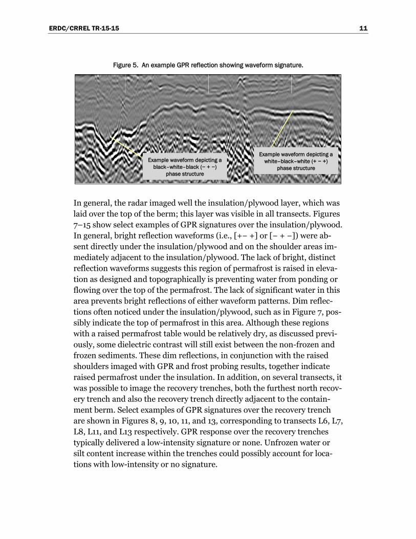
Because of the dielectric permittivity contrast between ice, moist thawed sediment, and water, it is possible to make qualitative assessments on the type of material the radar energy encountered (Figure 5). When the waves propagate from a region of lower dielectric permittivity to higher, such as from moist sediments to a water layer, the reflection will have a waveform of (+ − +), or white–black–white (viewed in grayscale). When the waves propagate from a region of higher dielectric permittivity to lower, such as when moving from moist sediments to substantial ice layer(s), the reflec-tions will have a waveform of (− + −), or black–white–black (viewed in grayscale). This study found that the areas upstream of the containment berm generally exhibited the (− + −) waveform, indicating the possibility of ice below the bottom of the active layer. When viewing transects close to Imikpuk Lake, it found that on approaching the lake, a strong reflector with (+− +) would emerge, suggesting water on the top of the permafrost.
ERDC/CRREL TR-15-15 11
Figure 5. An example GPR reflection showing waveform signature.
In general, the radar imaged well the insulation/plywood layer, which was laid over the top of the berm; this layer was visible in all transects. Figures 7–15 show select examples of GPR signatures over the insulation/plywood. In general, bright reflection waveforms (i.e., [+− +] or [− + −]) were ab-sent directly under the insulation/plywood and on the shoulder areas im-mediately adjacent to the insulation/plywood. The lack of bright, distinct reflection waveforms suggests this region of permafrost is raised in eleva-tion as designed and topographically is preventing water from ponding or flowing over the top of the permafrost. The lack of significant water in this area prevents bright reflections of either waveform patterns. Dim reflec-tions often noticed under the insulation/plywood, such as in Figure 7, pos-sibly indicate the top of permafrost in this area. Although these regions with a raised permafrost table would be relatively dry, as discussed previ-ously, some dielectric contrast will still exist between the non-frozen and frozen sediments. These dim reflections, in conjunction with the raised shoulders imaged with GPR and frost probing results, together indicate raised permafrost under the insulation. In addition, on several transects, it was possible to image the recovery trenches, both the furthest north recov-ery trench and also the recovery trench directly adjacent to the contain-ment berm. Select examples of GPR signatures over the recovery trench are shown in Figures 8, 9, 10, 11, and 13, corresponding to transects L6, L7, L8, L11, and L13 respectively. GPR response over the recovery trenches typically delivered a low-intensity signature or none. Unfrozen water or silt content increase within the trenches could possibly account for loca-tions with low-intensity or no signature.
Example waveform depicting a black–white–black (− + −)
phase structure
Example waveform depicting a white–black–white (+ − +)
phase structure
ERDC/CRREL TR-15-15 12
4.2 Probing results
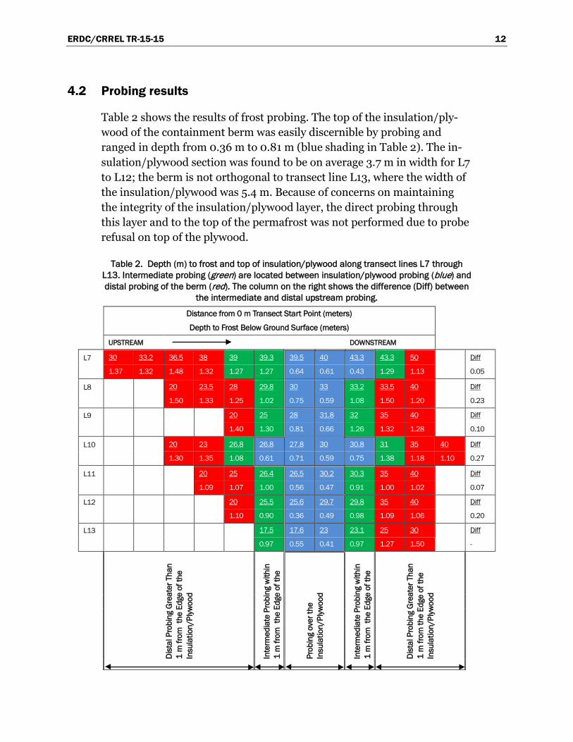
Table 2 shows the results of frost probing. The top of the insulation/ply-wood of the containment berm was easily discernible by probing and ranged in depth from 0.36 m to 0.81 m (blue shading in Table 2). The in-sulation/plywood section was found to be on average 3.7 m in width for L7 to L12; the berm is not orthogonal to transect line L13, where the width of the insulation/plywood was 5.4 m. Because of concerns on maintaining the integrity of the insulation/plywood layer, the direct probing through this layer and to the top of the permafrost was not performed due to probe refusal on top of the plywood.
Table 2. Depth (m) to frost and top of insulation/plywood along transect lines L7 through L13. Intermediate probing (green) are located between insulation/plywood probing (blue) and distal probing of the berm (red). The column on the right shows the difference (Diff) between
the intermediate and distal upstream probing.
Distance from 0 m Transect Start Point (meters)
Depth to Frost Below Ground Surface (meters)
UPSTREAM
DOWNSTREAM
L7 30 33.2 36.5 38 39 39.3 39.5 40 43.3 43.3 50 Diff
1.37 1.32 1.48 1.32 1.27 1.27 0.64 0.61 0.43 1.29 1.13 0.05
L8 20 23.5 28 29.8 30 33 33.2 33.5 40 Diff
1.50 1.33 1.25 1.02 0.75 0.59 1.08 1.50 1.20 0.23
L9 20 25 28 31.8 32 35 40 Diff
1.40 1.30 0.81 0.66 1.26 1.32 1.28 0.10
L10 20 23 26.8 26.8 27.8 30 30.8 31 35 40 Diff
1.30 1.35 1.08 0.61 0.71 0.59 0.75 1.38 1.18 1.10 0.27
L11 20 25 26.4 26.5 30.2 30.3 35 40 Diff
1.09 1.07 1.00 0.56 0.47 0.91 1.00 1.02 0.07
L12 20 25.5 25.6 29.7 29.8 35 40 Diff
1.10 0.90 0.36 0.49 0.98 1.09 1.06 0.20
L13 17.5 17.6 23 23.1 25 30 Diff
0.97 0.55 0.41 0.97 1.27 1.50 -
Dist
al P
robi
ng G
reat
er T
han
1 m
from
the
Edg
e of
the
Insu
latio
n/Pl
ywoo
d
Inte
rmed
iate
Pro
bing
with
in
1 m
from
the
Edg
e of
the
Prob
ing
over
the
Insu
latio
n/Pl
ywoo
d
Inte
rmed
iate
Pro
bing
with
in
1 m
from
the
Edg
e of
the
Dist
al P
robi
ng G
reat
er T
han
1 m
from
the
Edge
of t
he
Insu
latio
n/Pl
ywoo
d

ERDC/CRREL TR-15-15 13
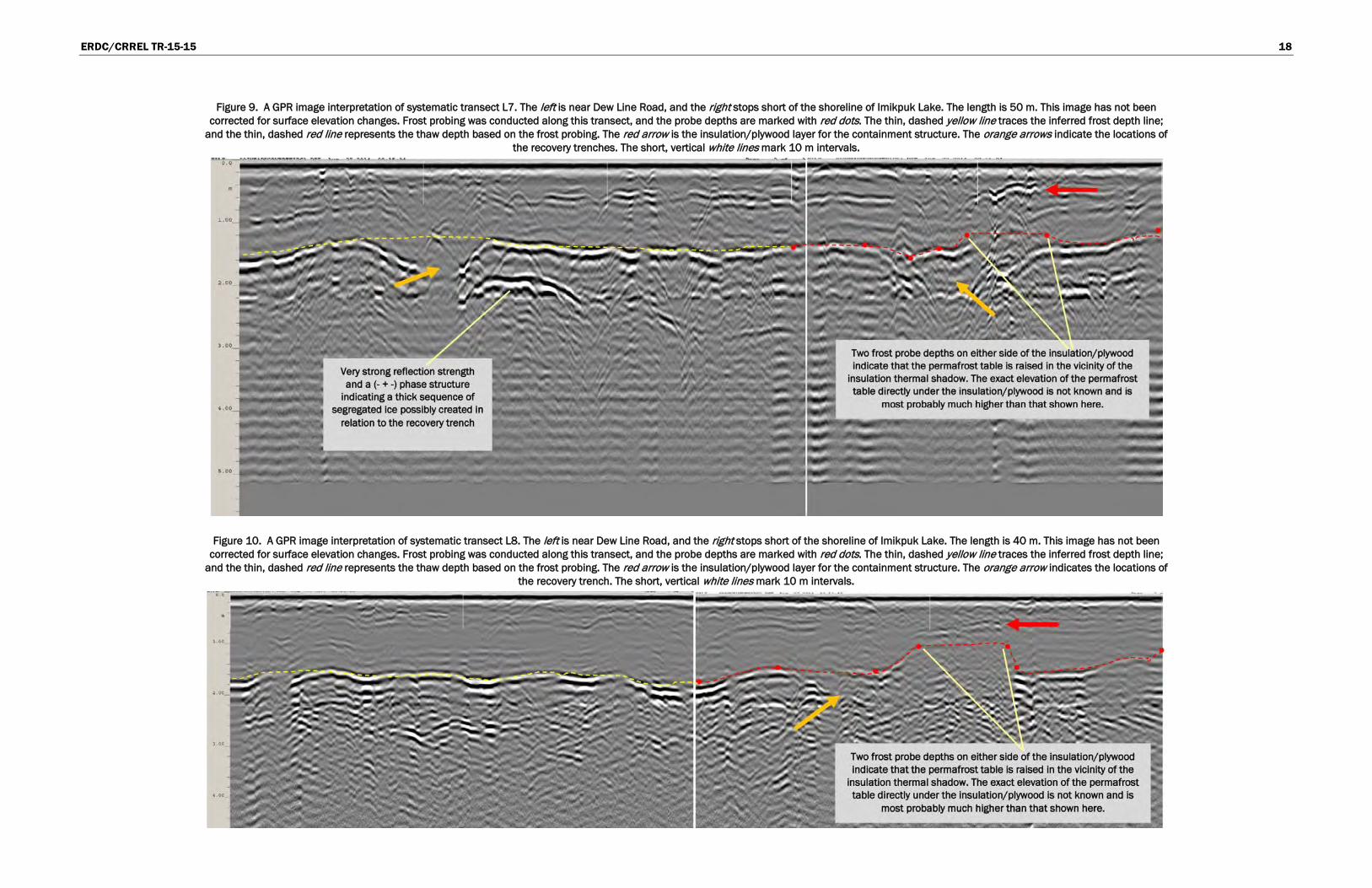
Intermediate probing was conducted within 1 m of the edges of the insula-tion/plywood layer in both upstream and downstream directions (green shading in Table 2); distal probing (red shading in Table 2) was conducted beyond (upstream and downstream) the intermediate probing. Generally, for a given transect, intermediate probing indicated a shallower depth to permafrost compared to distal probing, suggesting the insulation/plywood layer is contributing to a general decrease in the depth to permafrost along the berm. The difference in permafrost depth from intermediate probing and upstream distal probing is tabulated in Table 2 (difference values in the right column) and also shown visually in Figures 9 through 13. These values do not indicate the absolute rise in the permafrost table directly un-der the insulation/plywood but do indicate a transition from deeper per-mafrost depths more distal to the berm to shallower permafrost depths ad-jacent to and under the insulation/plywood.
4.3 Missing section of the containment berm
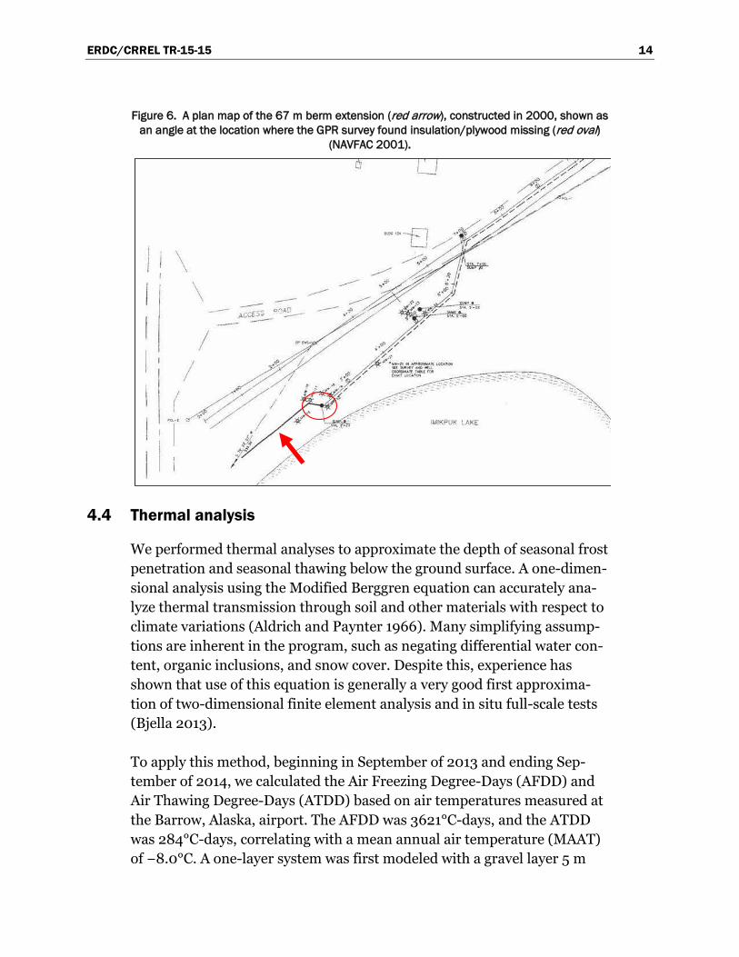
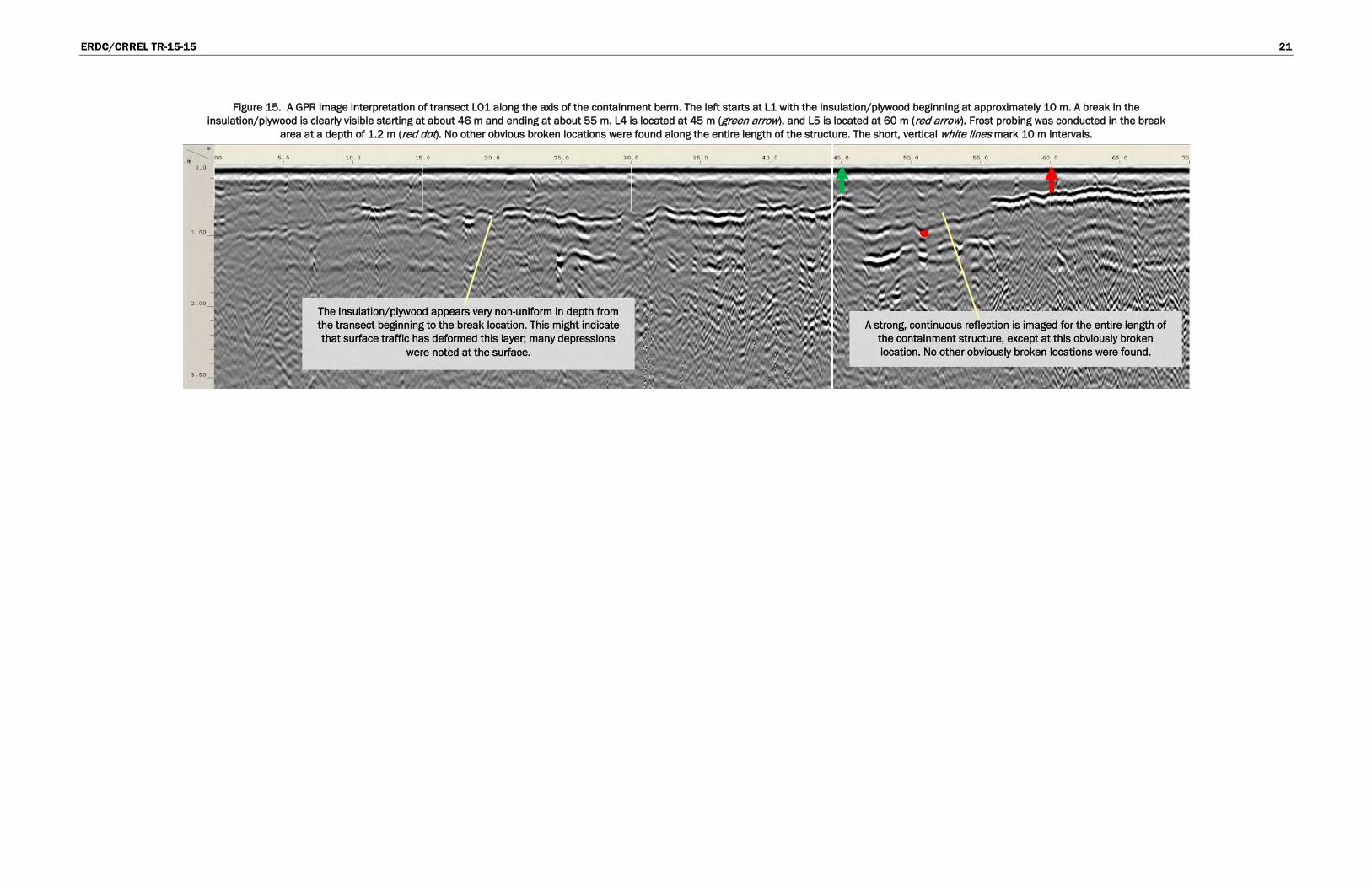
The long transect conducted above the axis of the containment structure was successful in imaging the insulation/plywood layer for the entire length of the containment structure. However, the area between L4 and L5 had no visible insulation/plywood in the GPR images (Figure 15). This area was intensely frost probed, and no insulation or plywood was found for a length of approximately 4 m though insulation/plywood was visible in both the L4 and L5 transects, which we confirmed with frost probing. The mineral sand and gravel surface in this area appeared reworked and disturbed and was also locally depressed compared to the adjacent ground. As noted earlier, the containment berm was extended in 2000; and a short angle connecting the old alignment with the new alignment was con-structed (Figure 4). This angle was known during the investigation, and the frost probing was conducted in a wide swath to ensure insulation/ply-wood was encountered if it existed. The plans show this was the former lo-cation of a sump on the adjacent recovery trench. The disturbed ground and locally depressed area suggest this sump was removed and is therefore the reason for the missing insulation/plywood. Figure 6 shows the area of missing insulation/plywood. During all the probing conducted in that area, no product odor was noticed.
ERDC/CRREL TR-15-15 14
Figure 6. A plan map of the 67 m berm extension (red arrow), constructed in 2000, shown as an angle at the location where the GPR survey found insulation/plywood missing (red oval)
(NAVFAC 2001).
4.4 Thermal analysis
We performed thermal analyses to approximate the depth of seasonal frost penetration and seasonal thawing below the ground surface. A one-dimen-sional analysis using the Modified Berggren equation can accurately ana-lyze thermal transmission through soil and other materials with respect to climate variations (Aldrich and Paynter 1966). Many simplifying assump-tions are inherent in the program, such as negating differential water con-tent, organic inclusions, and snow cover. Despite this, experience has shown that use of this equation is generally a very good first approxima-tion of two-dimensional finite element analysis and in situ full-scale tests (Bjella 2013).
To apply this method, beginning in September of 2013 and ending Sep-tember of 2014, we calculated the Air Freezing Degree-Days (AFDD) and Air Thawing Degree-Days (ATDD) based on air temperatures measured at the Barrow, Alaska, airport. The AFDD was 3621°C-days, and the ATDD was 284°C-days, correlating with a mean annual air temperature (MAAT) of −8.0°C. A one-layer system was first modeled with a gravel layer 5 m
ERDC/CRREL TR-15-15 15
thick (moisture content 2.5%) to simulate conditions outside the thermal regime of the insulated berm. The surface thaw n-factor was adjusted to 1.1 in the model so that with these input variables the thaw penetration ap-proximately matched the average thaw depth encountered during distal probing, which was 1.4 m. Using these input variables, we then modeled a three-layer system consisting of 0.6 m of gravel, 0.1 m of XPS insulation (moisture content 0%), and 5.0 m of gravel (moisture content 2.5%) to simulate conditions within the thermal regime of the insulated berm. The thaw penetration in this system achieved a depth of 0.74 m, or approxi-mately 0.14 m below the bottom of the insulation layer.
We conducted a sensitivity analysis by varying the water content up to 7 and also by varying the depth of the insulation within the modeled section; both variations showed no appreciable change in the thickness of thawed ground beyond the bottom of the XPS. Air temperature changes and sur-face thaw ‘n’ factor control the depth of thaw more considerably. Increas-ing the ATDD to 444°C-days increased the MAAT to −7°C, and the thaw depth increased to 0.8 m in the three-layer system. Normal climatic an-nual varying can achieve this degree of change in the MAAT; therefore, the annual depth of thaw is quite variable and helps to explain the existence of segregation ice at the top of the permafrost table.

ERDC/CRREL TR-15-15 16

ERDC/CRREL TR-15-15 17
Figure 7. A GPR image interpretation of the MWT. The MWT from AS-WP-101 to AS-WP-10 ended at the beginning of the sands of Imikpuk Lake shoreline. The length is approximately 50 m. This transect was not part of the systematic transects. The surface has been normalized to simulate the drop in surface elevation (approximated). The short, vertical white lines mark 10 m intervals. Frost depth probing was 1.4 m at AS-WP-101 (orange arrow) and 0.8 m at AS-WP-10 (green arrow). The thin, dashed yellow line traces the inferred frost depth reflector; and this yellow line has been raised a small amount to
prevent masking of that reflection. The red arrow is pointing to the containment berm insulation/plywood layer, and the two-tiered structure is clearly visible (Fig. 2). A definitive frost depth reflector is dimly visible under the insulation/plywood (yellow arrow). However the rise in the frost depth upstream and downstream of the structure is clearly evident. This image is vertically exaggerated; and the full-length,
vertical white line is a match line for assembling the image.
Figure 8. A GPR image interpretation of systematic transect L6. The left is near Dew Line Road, and the right stops short of the shoreline of Imikpuk Lake. The length is 50 m. This image has not been corrected for surface elevation changes, and no frost probing was conducted along this transect. The thin, dashed yellow line traces the inferred frost depth line; this line has been raised a small amount to prevent masking of the reflection used for interpretation. The red arrow is the insulation/plywood layer for the containment structure. The orange arrows indicate the locations of the recovery trenches. The
short, vertical white lines mark 10 m intervals.
ERDC/CRREL TR-15-15 18
Figure 9. A GPR image interpretation of systematic transect L7. The left is near Dew Line Road, and the right stops short of the shoreline of Imikpuk Lake. The length is 50 m. This image has not been corrected for surface elevation changes. Frost probing was conducted along this transect, and the probe depths are marked with red dots. The thin, dashed yellow line traces the inferred frost depth line;
and the thin, dashed red line represents the thaw depth based on the frost probing. The red arrow is the insulation/plywood layer for the containment structure. The orange arrows indicate the locations of the recovery trenches. The short, vertical white lines mark 10 m intervals.
Figure 10. A GPR image interpretation of systematic transect L8. The left is near Dew Line Road, and the right stops short of the shoreline of Imikpuk Lake. The length is 40 m. This image has not been corrected for surface elevation changes. Frost probing was conducted along this transect, and the probe depths are marked with red dots. The thin, dashed yellow line traces the inferred frost depth line;
and the thin, dashed red line represents the thaw depth based on the frost probing. The red arrow is the insulation/plywood layer for the containment structure. The orange arrow indicates the locations of the recovery trench. The short, vertical white lines mark 10 m intervals.

ERDC/CRREL TR-15-15 19
Figure 11. A GPR image interpretation of systematic transect L11. The left is just north of Dew Line Road, and the right stops short of the shoreline of Imikpuk Lake. The length is 40 m. This image has not been corrected for surface elevation changes. Frost probing was conducted along this transect, and the probe depths are marked with red dots. The thin, dashed yellow line traces the inferred frost depth line; and the thin, dashed red line represents the thaw depth based on the frost probing. The red arrow is the insulation/plywood layer for the containment structure. The orange arrow indicates a location
where reflections are abruptly softened or muted. The short, vertical white lines mark 10 m intervals.
Figure 12. A GPR image interpretation of systematic transect L12. The left is just north of Dew Line Road, and the right stops short of the shoreline of Imikpuk Lake. The length is 40 m. This image has not been corrected for surface elevation changes. Frost probing was conducted along this transect, and the probe depths are marked with red dots. The thin, dashed yellow line traces the inferred frost depth line; and the thin, dashed red line represents the thaw depth based on the frost probing. The red arrow is the insulation/plywood layer for the containment structure. The short, vertical white lines mark 10
m intervals.
ERDC/CRREL TR-15-15 20
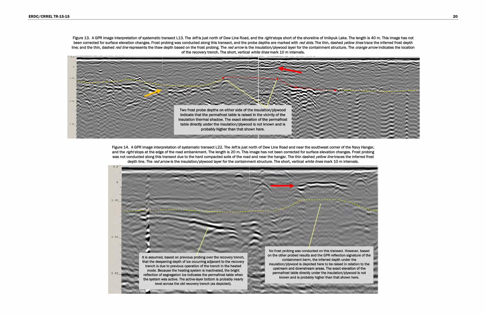
Figure 13. A GPR image interpretation of systematic transect L13. The left is just north of Dew Line Road, and the right stops short of the shoreline of Imikpuk Lake. The length is 40 m. This image has not been corrected for surface elevation changes. Frost probing was conducted along this transect, and the probe depths are marked with red dots. The thin, dashed yellow lines trace the inferred frost depth
line; and the thin, dashed red line represents the thaw depth based on the frost probing. The red arrow is the insulation/plywood layer for the containment structure. The orange arrow indicates the location of the recovery trench. The short, vertical white lines mark 10 m intervals.
Figure 14. A GPR image interpretation of systematic transect L22. The left is just north of Dew Line Road and near the southwest corner of the Navy Hangar, and the right stops at the edge of the road embankment. The length is 20 m. This image has not been corrected for surface elevation changes. Frost probing was not conducted along this transect due to the hard compacted soils of the road and near the hangar. The thin dashed yellow line traces the inferred frost
depth line. The red arrow is the insulation/plywood layer for the containment structure. The short, vertical white lines mark 10 m intervals.
ERDC/CRREL TR-15-15 21
Figure 15. A GPR image interpretation of transect L01 along the axis of the containment berm. The left starts at L1 with the insulation/plywood beginning at approximately 10 m. A break in the insulation/plywood is clearly visible starting at about 46 m and ending at about 55 m. L4 is located at 45 m (green arrow), and L5 is located at 60 m (red arrow). Frost probing was conducted in the break
area at a depth of 1.2 m (red dot). No other obvious broken locations were found along the entire length of the structure. The short, vertical white lines mark 10 m intervals.

ERDC/CRREL TR-15-15 22

ERDC/CRREL TR-15-15 23
5 Results
The transition zone between the top of the permafrost and the bottom of the active layer generally provides a substantial accumulation of segrega-tion ice, enough to be seen as a moderate or better GPR reflection. Alt-hough the transition zone is theoretically still frozen and technically is not the bottom of the active layer, in most cases this ice is within centimeters of the active-layer thaw. Under average annual air temperature scenarios, this icy layer nearly represents the top of the permafrost and the bottom of the active layer. If significant segregation ice is not present at this transi-tion zone, active-layer water often pools on the top of the permafrost; and this, too, is readily detected.
For this investigation, the GPR returns were as expected for this type of permafrost terrain and the type of surface cover encountered at the site. Although it was not possible to frost probe all transects due to the com-pacted surface of the fill material, the depths of the GPR-inferred bottom of the active layer correlated well with the probing results. Examination of the probed depths overlaid on the GPR radar grams and in conjunction with sloping reflections rising upwards towards the insulation/plywood in-dicates that this structure is achieving a substantial rise in the permafrost table. It was not possible to physically measure the exact amount of this rise directly under the insulation/plywood layer due to probing refusal.
Although direct imaging of a reflection surface that also coincides with the depth of frost probing is probably the most useful visual determination of thaw depth on a radar image, the lack of a bright reflection surface is also qualitative information. As mentioned earlier, dim GPR reflections were visible directly under the insulation/plywood and were also generally dim for a distance of approximately 1.5 m on either side of the edges of the in-sulation/plywood. Hypothetically, if the permafrost table was not rising upwards in this area, segregated ice reflections or water reflections would likely be visible here. In most of the radar grams, a reflection of either wa-ter or ice was noticeable nearly everywhere except in the thermal shadow of the insulation/plywood. This implies that this area is consistently raised and prevents water from pooling in this area, which also prevents the crea-

ERDC/CRREL TR-15-15 24
tion of segregated ice. The two lines surveyed along the axis of the struc-ture provided excellent reflections for the entire length, except for the bro-ken location found between L4 and L5.
Some areas in the radar grams were visibly devoid of any reflection signa-ture. They had a softened or muted texture and appeared and ended rather abruptly. One example is in Figure 11 where the area is noted with an or-ange arrow. These regions indicate the GPR signal was attenuated due to some property of the sediment at that location where water and high per-centages of mineralogical clays or silts are good attenuators of radar en-ergy. However, it is possible that the momentary lifting of the radar an-tenna from the surface when encountering rough terrain, as experienced at the NARL facility, can cause this effect.
ERDC/CRREL TR-15-15 25
6 Conclusions
This study used three methods to ascertain the permafrost depth under the insulation/plywood layer in the containment berm. GPR imaging re-vealed that, on most transects, it was possible to see a rise in the perma-frost table when approaching the containment berm from either the up-stream or the downstream edge. This was possible when that section contained either segregation ice (indicating the top of the permafrost) or pooled water (indicating the bottom of the active layer). Frost probing was used to verify that the GPR reflections inferred to be either segregation ice or water were in fact the top of the permafrost or the bottom of the active layer. The results of the probing correlated well with the imaging. Lastly, the one-dimensional thermal analysis provided a check to confirm that the design of the structure would produce a significant rise in the permafrost table; and this was the case. However, the analysis did not investigate im-perfections that may have occurred during construction of the berm or damage that has occurred since construction. Of the approximately 2100 m of lineal GPR imaging performed during this investigation, only one location appeared to have incurred damage that one would expect to destroy the thermal integrity of the containment; and this was located at the western end between L4 and L5 where insulation appears to be miss-ing.
Based on this information, the berm is raising the permafrost table under the insulation/plywood. From the resolution of this survey, which was de-termined by transect separation, it was not possible to ascertain if a local irregularity may exist that provides a pathway for water to move from the upstream side of the berm to the downstream side of the berm. However, a potential pathway could possibly exist where the insulation appears to be missing.

ERDC/CRREL TR-15-15 26
References Aldrich, H. P., Jr, and H. M. Paynter. 1966. Depth of Frost Penetration in Non-Uniform
Soil. CRREL Special Report 104. Hanover, NH: U.S. Army Cold Regions Research and Engineering Laboratory.
Bjella, K. 2013. Thule Air Base Airfield White Painting and Permafrost Investigation: Phase I–IV. ERDC/CRREL TR-13-8. Hanover, NH: U.S. Army Engineer Research and Development Center.
Naval Facilities Engineering Command Northwest (NAVFAC). 1998. Closeout Report—Technical Summary for a containment Berm and Recovery Trench Project, NARL, Point Barrow, Alaska. Silverdale, WA: Naval Facilities Engineering Command Northwest.
Naval Facilities Engineering Command Northwest (NAVFAC). 2001. Barrow Work Summary—Environmental Remediation for the Containment Berm and Recovery Trench, Modification 1, NARL, Point Barrow, Alaska. Silverdale, WA: Naval Facilities Engineering Command Northwest.
Naval Facilities Engineering Command Northwest (NAVFAC). 2014. Annual Monitoring Report—Airstrip, Powerhouse, and Former Bulk Fuel Tank Farm Sites, NARL, Point Barrow, Alaska. Silverdale, WA: Naval Facilities Engineering Command Northwest.
Shur, Y., K. M. Hinkel, and F. E. Nelson. 2005. The transient layer: implications for geocryology and climate‐change science. Permafrost and Periglacial Processes 16 (1): 5–17.

ERDC/CRREL TR-15-15 27
Appendix A: GPS Transect Coordinates Table A1. Summary Table of GPR Transect Coordinates. All coordinates are in WGS 1984 UTM Zone 4N (World Geodetic System 1984 Universal Transverse Mercator Zone 4 North)
and were collected using a hand-held, recreational-grade GPS.
Transect Number
Northing (transect start point)
Easting (transect start point)
Northing
(transect end point) Easting
(transect end point) L1 7916261.72 583714.37 7916216.99 583702.82 L2 7916263.82 583729.37 7916214.73 583717.49 L3 7916261.84 583742.44 7916213.67 583731.74 L4 7916261.13 583754.65 7916212.67 583746.84 L5 7916262.42 583770.05 7916211.28 583761.59 L6 7916259.55 583784.14 7916210.55 583776.30 L7 7916256.56 583801.69 7916208.41 583791.42 L8 7916245.35 583815.55 7916207.39 583806.40 L9 7916242.87 583829.20 7916206.36 583821.13 L10 7916240.54 583843.45 7916205.03 583836.08 L11 7916239.88 583860.92 7916203.95 583851.18 L12 7916237.74 583875.88 7916202.58 583866.02 L13 7916234.86 583888.58 7916200.60 583881.36 L14 7916236.60 583904.22 7916203.08 583896.85 L15 7916235.52 583920.22 7916204.48 583911.82 L16 7916236.96 583937.60 7916205.82 583926.15 L17 7916240.82 583950.56 7916207.52 583940.96 L18 7916241.51 583963.91 7916209.18 583956.13 L19 7916233.14 583977.12 7916211.08 583971.13 L20 7916232.10 583994.37 7916211.44 583986.30 L21 7916233.88 584010.67 7916211.84 584003.15 L22 7916224.29 584024.03 7916209.45 584016.85 L23 7916219.28 584033.91 7916207.77 584031.25 L24 7916216.50 584048.59 7916206.51 584047.83 L25 7916212.57 584062.13 7916204.53 584059.99 L26 7916207.11 584077.25 7916190.01 584070.66 L27 7916201.18 584090.20 7916181.82 584084.24 L28 7916195.05 584104.43 7916175.55 584098.11 L29 7916189.45 584118.28 7916159.68 584110.96 L30 7916183.98 584132.95 7916154.54 584124.62 L31 7916188.71 584150.22 7916158.52 584140.89 L32 7916172.35 584160.49 7916161.00 584157.05 L33 7916164.14 584173.25 7916152.72 584170.22 L34 7916155.51 584185.21 7916143.71 584182.74 L35 7916145.26 584196.48 7916133.30 584193.24 L36 7916139.71 584210.94 7916119.96 584200.08 MWT 7916237.38 583927.87 7916189.41 583890.64
ERDC/CRREL TR-15-15 28
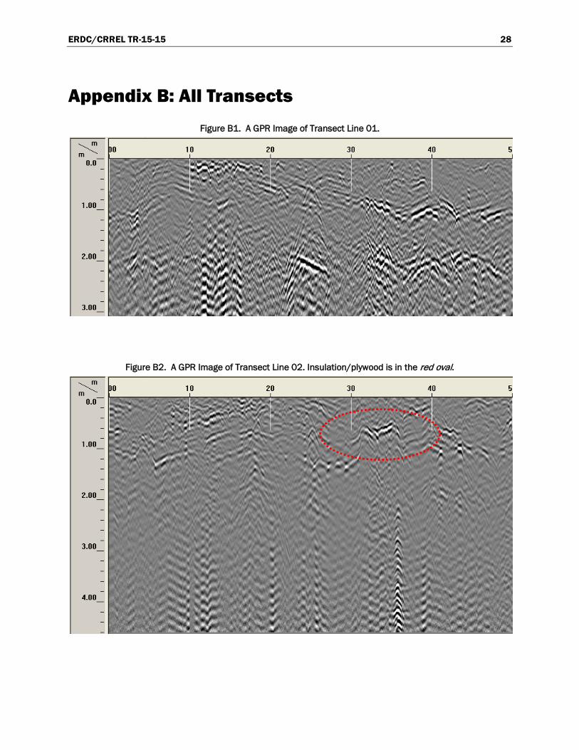
Appendix B: All Transects Figure B1. A GPR Image of Transect Line 01.
Figure B2. A GPR Image of Transect Line 02. Insulation/plywood is in the red oval.

ERDC/CRREL TR-15-15 29
Figure B3. A GPR Image of Transect Line 03. Insulation/plywood is in the red oval.
Figure B4. A GPR Image of Transect Line 04. Insulation/plywood is in the red oval.
Figure B5. A GPR Image of Transect Line 05. Insulation/plywood is in the red oval.

ERDC/CRREL TR-15-15 30
Figure B6. A GPR Image of Transect Line 06. Insulation/plywood is in the red oval.
Figure B7. A GPR Image of Transect Line 07. Insulation/plywood is in the red oval.
Figure B8. A GPR Image of Transect Line 08. Insulation/plywood is in the red oval.

ERDC/CRREL TR-15-15 31
Figure B9. A GPR Image of Transect Line 09. Insulation/plywood is in the red oval.
Figure B10. A GPR Image of Transect Line 10. Insulation/plywood is in the red oval.
Figure B11. A GPR Image of Transect Line 11. Insulation/plywood is in the red oval.

ERDC/CRREL TR-15-15 32
Figure B12. A GPR Image of Transect Line 12. Insulation/plywood is in the red oval.
Figure B13. A GPR Image of Transect Line 13. Insulation/plywood is in the red oval.
Figure B14. A GPR Image of Transect Line 14. Insulation/plywood is in the red oval.

ERDC/CRREL TR-15-15 33
Figure B15. A GPR Image of Transect Line 15. Insulation/plywood is in the red oval.
Figure B16. A GPR Image of Transect Line 16. Insulation/plywood is in the red oval.
Figure B17. A GPR Image of Transect Line 17. Insulation/plywood is in the red oval.
ERDC/CRREL TR-15-15 34
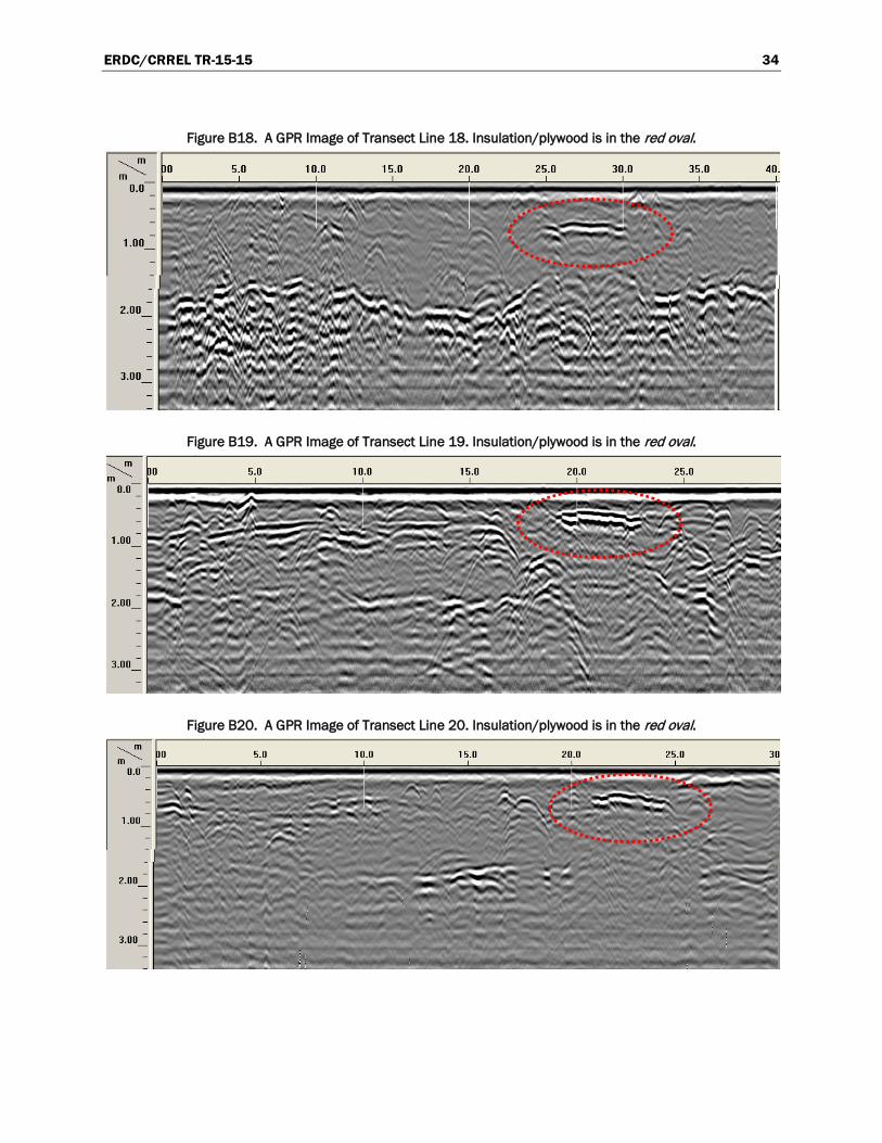
Figure B18. A GPR Image of Transect Line 18. Insulation/plywood is in the red oval.
Figure B19. A GPR Image of Transect Line 19. Insulation/plywood is in the red oval.
Figure B20. A GPR Image of Transect Line 20. Insulation/plywood is in the red oval.

ERDC/CRREL TR-15-15 35
Figure B21. A GPR Image of Transect Line 21. Insulation/plywood is in the red oval.
Figure B22. A GPR Image of Transect Line 22. Insulation/plywood is in the red oval.

ERDC/CRREL TR-15-15 36
Figure B23. A GPR Image of Transect Line 23. Insulation/plywood is in the red oval.
Figure B24. A GPR Image of Transect Line 24. Insulation/plywood is in the red oval.

ERDC/CRREL TR-15-15 37
Figure B25. A GPR Image of Transect Line 25. Insulation/plywood is in the red oval.
Figure B26. A GPR Image of Transect Line 26. Insulation/plywood is in the red oval.
ERDC/CRREL TR-15-15 38
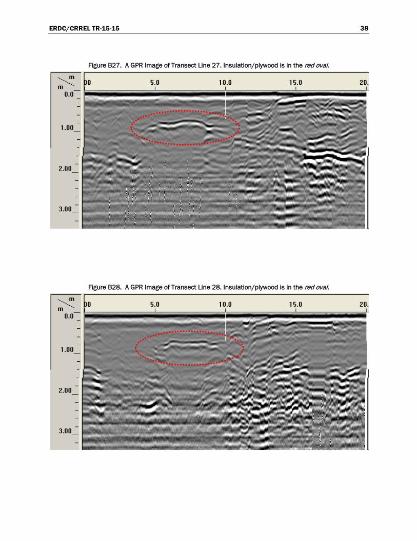
Figure B27. A GPR Image of Transect Line 27. Insulation/plywood is in the red oval.
Figure B28. A GPR Image of Transect Line 28. Insulation/plywood is in the red oval.

ERDC/CRREL TR-15-15 39
Figure B29. A GPR Image of Transect Line 29. Insulation/plywood is in the red oval.
Figure B30. A GPR Image of Transect Line 30. Insulation/plywood is in the red oval.
Figure B31. A GPR Image of Transect Line 31. Insulation/plywood is in the red oval.

ERDC/CRREL TR-15-15 40
Figure B32. A GPR Image of Transect Line 32. Insulation/plywood is in the red oval.
Figure B33. A GPR Image of Transect Line 33. Insulation/plywood is in the red oval.
ERDC/CRREL TR-15-15 41
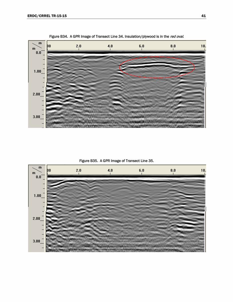
Figure B34. A GPR Image of Transect Line 34. Insulation/plywood is in the red oval.
Figure B35. A GPR Image of Transect Line 35.
ERDC/CRREL TR-15-15 42
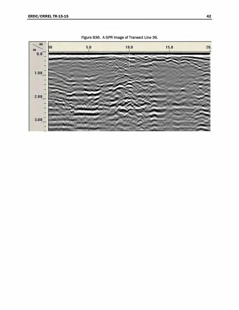
Figure B36. A GPR Image of Transect Line 36.

ER
DC/CR
REL TR
-15-15 43
Figure B37. The transect along the top of the containment berm. Line 01 through Line 07.
Figure B38. The transect along the top of the containment berm. Line 08 through Line 14.
ER
DC/CR
REL TR
-15-15 44
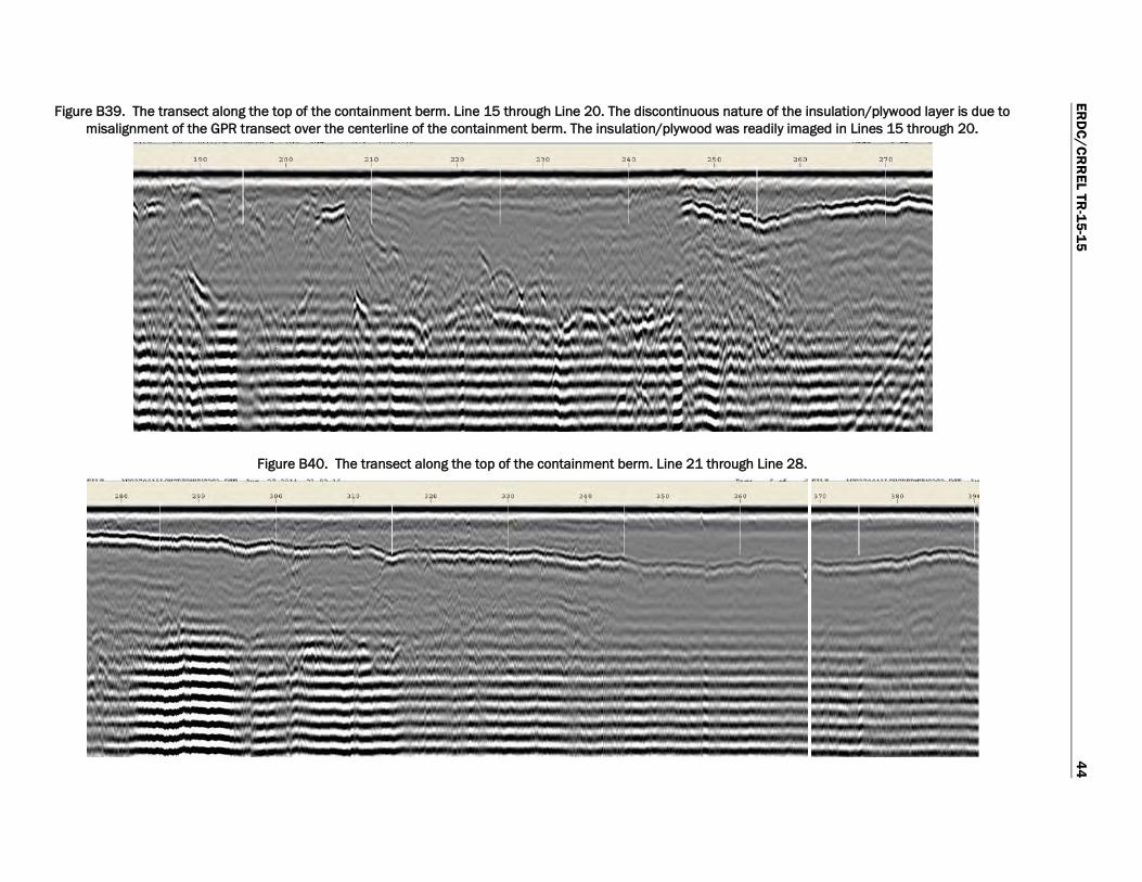
Figure B39. The transect along the top of the containment berm. Line 15 through Line 20. The discontinuous nature of the insulation/plywood layer is due to misalignment of the GPR transect over the centerline of the containment berm. The insulation/plywood was readily imaged in Lines 15 through 20.
Figure B40. The transect along the top of the containment berm. Line 21 through Line 28.

ER
DC/CR
REL TR
-15-15 45
Figure B41. The transect along the top of the containment berm. Line 28 through Line 36. (Horizontal scale not continuous from the previous figure due to software deficiency.)

REPORT DOCUMENTATION PAGE Form Approved
OMB No. 0704-0188 Public reporting burden for this collection of information is estimated to average 1 hour per response, including the time for reviewing instructions, searching existing data sources, gathering and maintaining the data needed, and completing and reviewing this collection of information. Send comments regarding this burden estimate or any other aspect of this collection of information, including suggestions for reducing this burden to Department of Defense, Washington Headquarters Services, Directorate for Information Operations and Reports (0704-0188), 1215 Jefferson Davis Highway, Suite 1204, Arlington, VA 22202-4302. Respondents should be aware that notwithstanding any other provision of law, no person shall be subject to any penalty for failing to comply with a collection of information if it does not display a currently valid OMB control number. PLEASE DO NOT RETURN YOUR FORM TO THE ABOVE ADDRESS. 1. REPORT DATE (DD-MM-YYYY)
October 2015 2. REPORT TYPE
Technical Report/Final 3. DATES COVERED (From - To)
4. TITLE AND SUBTITLE
Naval Arctic Research Laboratory (NARL) Subsurface Containment Berm Investigation
5a. CONTRACT NUMBER
5b. GRANT NUMBER
5c. PROGRAM ELEMENT NUMBER
6. AUTHOR(S)
Kevin Bjella
5d. PROJECT NUMBER
5e. TASK NUMBER MIPR# N6247314MPT0006
5f. WORK UNIT NUMBER
7. PERFORMING ORGANIZATION NAME(S) AND ADDRESS(ES) 8. PERFORMING ORGANIZATION REPORT NUMBER
U.S. Army Engineer Research and Development Center (ERDC) Cold Regions Research and Engineering Laboratory (CRREL) Alaska Research Office Building 4070, 9th Street Fort Wainwright, AK 99703
ERDC/CRREL TR-15-15
9. SPONSORING / MONITORING AGENCY NAME(S) AND ADDRESS(ES) 10. SPONSOR/MONITOR’S ACRONYM(S) Naval Facilities Engineering Command Northwest 1101 Tautog Circle Silverdale, WA 98315
NAVFAC NW 11. SPONSOR/MONITOR’S REPORT NUMBER(S)
12. DISTRIBUTION / AVAILABILITY STATEMENT Approved for public release; distribution is unlimited.
13. SUPPLEMENTARY NOTES
14. ABSTRACT
The former Navy Arctic Research Laboratory Airstrip Site in Barrow, Alaska, has a history of fuel spills. Various methods have been used to remediate the site, including installing a subsurface containment berm and associated recovery trenches. The containment berm was designed to create a raised permafrost feature that effectively prevents free product migrating from the upstream side to the downstream side.
This study focused on using non-intrusive ground-penetrating-radar (GPR) techniques coupled with ground probing and desktop thermal analyses to assess if these methods could help to determine whether the containment berm is functioning as designed (i.e., effectively decreasing active-layer thickness and raising the permafrost table).
The results demonstrate that these GPR methods were useful for this study and that the berm is effectively raising the permafrost table along the survey transects explored.
15. SUBJECT TERMS Barrow Alaska Containment berm
Geophysical methods Ground-penetrating radar Permafrost characterization
16. SECURITY CLASSIFICATION OF: 17. LIMITATION OF ABSTRACT
18. NUMBER OF PAGES
19a. NAME OF RESPONSIBLE PERSON
a. REPORT
Unclassified
b. ABSTRACT
Unclassified
c. THIS PAGE
Unclassified SAR 54 19b. TELEPHONE NUMBER (include area code)
Standard Form 298 (Rev. 8-98) Prescribed by ANSI Std. 239.18