EPSON CX3500 - 3650-3600-4500-4600 - Service Manual
205
EPSON STYLUS CX3500/CX3650/CX3600/ CX4500/CX4600 Color Inkjet Printer SEOT04-004 SERVICE MANUAL
-
Upload
lordtulkas -
Category
Documents
-
view
33 -
download
9
Transcript of EPSON CX3500 - 3650-3600-4500-4600 - Service Manual

EPSON STYLUS CX3500/CX3650/CX3600/CX4500/CX4600
Color Inkjet Printer
SEOT04-004
SERVICE MANUAL

PRECAUTIONSPrecautionary notations throughout the text are categorized relative to 1)Personal injury and 2) damage to equipment.
DANGER Signals a precaution which, if ignored, could result in serious or fatal personal injury. Great caution should be exercised in performing procedures preceded by DANGER Headings.
WARNING Signals a precaution which, if ignored, could result in damage to equipment.
The precautionary measures itemized below should always be observed when performing repair/maintenance procedures.
DANGER
1. ALWAYS DISCONNECT THE PRODUCT FROM THE POWER SOURCE AND PERIPHERAL DEVICES PERFORMING ANY MAINTENANCE OR REPAIR PROCEDURES.
2. NO WORK SHOULD BE PERFORMED ON THE UNIT BY PERSONS UNFAMILIAR WITH BASIC SAFETY MEASURES AS DICTATED FOR ALL ELECTRONICS TECHNICIANS IN THEIR LINE OF WORK.
3. WHEN PERFORMING TESTING AS DICTATED WITHIN THIS MANUAL, DO NOT CONNECT THE UNIT TO A POWER SOURCE UNTIL INSTRUCTED TO DO SO. WHEN THE POWER SUPPLY CABLE MUST BE CONNECTED, USE EXTREME CAUTION IN WORKING ON POWER SUPPLY AND OTHER ELECTRONIC COMPONENTS.
4. WHEN DISASSEMBLING OR ASSEMBLING A PRODUCT, MAKE SURE TO WEAR GLOVES TO AVOID INJURIER FROM METAL PARTS WITH SHARP EDGES.
WARNING
1. REPAIRS ON EPSON PRODUCT SHOULD BE PERFORMED ONLY BY AN EPSON CERTIFIED REPAIR TECHNICIAN.2. MAKE CERTAIN THAT THE SOURCE VOLTAGES IS THE SAME AS THE RATED VOLTAGE, LISTED ON THE SERIAL NUMBER/
RATING PLATE. IF THE EPSON PRODUCT HAS A PRIMARY AC RATING DIFFERENT FROM AVAILABLE POWER SOURCE, DO NOT CONNECT IT TO THE POWER SOURCE.
3. ALWAYS VERIFY THAT THE EPSON PRODUCT HAS BEEN DISCONNECTED FROM THE POWER SOURCE BEFORE REMOVING OR REPLACING PRINTED CIRCUIT BOARDS AND/OR INDIVIDUAL CHIPS.
4. IN ORDER TO PROTECT SENSITIVE MICROPROCESSORS AND CIRCUITRY, USE STATIC DISCHARGE EQUIPMENT, SUCH AS ANTI-STATIC WRIST STRAPS, WHEN ACCESSING INTERNAL COMPONENTS.
5. REPLACE MALFUNCTIONING COMPONENTS ONLY WITH THOSE COMPONENTS BY THE MANUFACTURE; INTRODUCTION OF SECOND-SOURCE ICs OR OTHER NONAPPROVED COMPONENTS MAY DAMAGE THE PRODUCT AND VOID ANY APPLICABLEEPSON WARRANTY.

T res of the printer. The instructions and p ecautions on the preceding page.
TC
C
C
C
C
C
C
s Manual
ughout this manual either to provide cific topic or to warn of possible danger
an action. Be aware of all symbols when d NOTE, CAUTION, or WARNING
ting or maintenance procedure, practice f not strictly observed, could result in .
ting or maintenance procedure, practice, f not strictly observed, could result in truction of, equipment.
perating or maintenance procedure, n that is necessary to accomplish a task lso provide additional information that is c subject, or comment on the results previous action.
ting or maintenance procedure, practice not strictly observed, could result in injury
rticular task must be carried out ain standard after disassembly and y, otherwise the quality of the stion may be adversely affected.
About This Manualhis manual describes basic functions, theory of electrical and mechanical operations, maintenance and repair procedurocedures included herein are intended for the experienced repair technicians, and attention should be given to the pr
Manual Configuration
his manual consists of six chapters and Appendix.HAPTER 1.PRODUCT DESCRIPTIONS
Provides a general overview and specifications of the product.
HAPTER 2.OPERATING PRINCIPLESDescribes the theory of electrical and mechanical operations of the product.
HAPTER 3.TROUBLESHOOTINGDescribes the step-by-step procedures for the troubleshooting.
HAPTER 4.DISASSEMBLY / ASSEMBLYDescribes the step-by-step procedures for disassembling and assembling the product.
HAPTER 5.ADJUSTMENTProvides Epson-approved methods for adjustment.
HAPTER 6.MAINTENANCEProvides preventive maintenance procedures and the lists of Epson-approved lubricants and adhesives required for servicing the product.
HAPTER 7.APPENDIXProvides the following additional information for reference:• Connector pin assignments• Electric circuit boards components layout• Electrical circuit boards schematics• Exploded diagram & Parts List
Symbols Used in thi
Various symbols are used throadditional information on a spepresent during a procedure orthey are used, and always reamessages.
Indicates an operaor condition that, iinjury or loss of life
Indicates an operaor condition that, idamage to, or des
May indicate an opractice or conditioefficiently. It may arelated to a specifiachieved through a
I.ndicates an operaor condition that, ifor loss of life.
Indicates that a paaccording to a certbefore re-assemblcomponents in que
NO
Revision Status
TE: Any illustrations or photos of the printer without a card slot are based on the Stylus CX3500/3600/CX3650.
Revision Issued Date Description
A 2004/8/18 First Release

Ch
1.1
1.2
1.3
1.4
1.5(on
1.6
anel Status ............................................... 47................................................................... 50................................................................... 51
INCIPLES
................................................................... 53
................................................................... 53
................................................................... 53
................................................................... 54
................................................................... 56 Mechanism ............................................. 58................................................................. 63
................................................................... 66
................................................................... 68hanism....................................................... 68g Principles.............................................. 70................................................................... 71................................................................... 72
TING
................................................................... 80t Occurrence Causes.............................. 80.................................................................. 85n-Based Troubleshooting....................... 105
ND ASSEMBLY
................................................................. 114
................................................................. 114
................................................................. 115
CONTENTS
apter 1 PRODUCT DESCRIPTION
Overview................................................................................................. 91.1.1 Features .......................................................................................... 9Specifications ...................................................................................... 11
1.2.1 Printer specifications ..................................................................... 111.2.2 Scanner specifications .................................................................. 191.2.3 Common........................................................................................ 20Interface................................................................................................ 22
1.3.1 USB Interface ................................................................................ 221.3.2 Standard Card Slots (only for Stylus CX4500/CX4600) ........................................................... 23Stand-alone Copy ................................................................................ 25
1.4.1 Basic Specifications ...................................................................... 251.4.2 Copy Speed................................................................................... 261.4.3 Configuration for copying .............................................................. 261.4.4 Relation between original and copy .............................................. 27Memory Card Print
ly for Stylus CX4500/CX4600) .............................................................. 301.5.1 Basic Specifications ...................................................................... 301.5.2 Functions....................................................................................... 311.5.3 Index Sheet ................................................................................... 331.5.4 Layout and Paper Type, Paper Size ............................................. 361.5.5 Options .......................................................................................... 361.5.6 Trimming Function......................................................................... 361.5.7 Assignment Rules for Photo Frame Numbers and Rotation ......... 371.5.8 Layout Drawings............................................................................ 381.5.9 Relation between Paper Type and Quality.................................... 40Control Panel ....................................................................................... 41
1.6.1 Buttons .......................................................................................... 411.6.2 Indicators....................................................................................... 411.6.3 Operations..................................................................................... 43
1.6.4 Printer Condition and P1.6.5 Memory Functions......1.6.6 Printer Initialization.....
Chapter 2 OPERATING PR
2.1 Overview ...........................2.2 Printer Mechanism ...........
2.2.1 Printer Mechanism .....2.2.2 Print Head ..................2.2.3 Carriage Mechanism ..2.2.4 Paper Loading/Feeding2.2.5 Ink System Mechanism2.2.6 Ink Sequence .............
2.3 Scanner Mechanism.........2.3.1 Scanner Carriage Mec
2.4 Electrical Circuit Operatin2.4.1 PSB/PSE Board .........2.4.2 C571/577 Main Board
Chapter 3 TROUBLESHOO
3.1 Overview ...........................3.2 Error Indications and Faul3.3 Troubleshooting ................
3.3.1 Superficial Phenomeno
Chapter 4 DISASSEMBLY A
4.1 Overview ...........................4.1.1 Precautions ................4.1.2 Tools ..........................

4.2Me4.3
Ch
5.1
5.2
................................................................. 165
................................................................. 165ture code................................................ 165
t ............................................................... 165ent .......................................................... 166
................................................................. 167
................................................................. 167stment ..................................................... 168tion control .............................................. 168................................................................. 168ment Program ....................................... 170................................................................. 170oning adjustment .................................... 173
................................................................. 175
................................................................. 175
................................................................. 175
................................................................. 177
................................................................ 182
................................................................ 182
................................................................ 188
................................................................ 192................................................................. 197................................................................. 199
4.1.3 Work Completion Check.............................................................. 116Caution regarding assembling/disassembling of the Printer
chanism, and how to ensure of quality on re-assembled product . 117Disassembly....................................................................................... 118
4.3.1 Document Cover ......................................................................... 1194.3.2 Paper Support Assy. ................................................................... 1204.3.3 Stacker Assy. .............................................................................. 1204.3.4 Scanner Unit................................................................................ 1214.3.5 Panel Unit.................................................................................... 1264.3.6 Housing Upper ............................................................................ 1274.3.7 Print Head ................................................................................... 1284.3.8 Printer Mechanism ...................................................................... 1304.3.9 PS Board Unit.............................................................................. 1334.3.10 Waste Ink Pads ......................................................................... 1344.3.11 Main Board Unit......................................................................... 1364.3.12 ASF Unit .................................................................................... 1414.3.13 Holder Shaft Unit ....................................................................... 1434.3.14 CR Guide Frame ....................................................................... 1464.3.15 CR Motor ................................................................................... 1474.3.16 PF Motor.................................................................................... 1484.3.17 Carriage Unit ............................................................................. 1494.3.18 Paper Guide Upper Unit ............................................................ 1524.3.19 Front Frame............................................................................... 1534.3.20 EJ Frame Unit ........................................................................... 1544.3.21 Ink System Unit ......................................................................... 1564.3.22 Paper Guide Front Unit ............................................................. 1574.3.23 PG Sensor................................................................................. 1584.3.24 PF Roller Unit ............................................................................ 159
apter 5 ADJUSTMENT
Overview............................................................................................. 1625.1.1 Required Adjustment................................................................... 162Adjustment by using adjustment program ..................................... 164
5.2.1 EEPROM Data Copy................................................................... 1645.2.2 Waste ink pad counter................................................................. 1645.2.3 Destination setting....................................................................... 1655.2.4 Initialize PF deterioration offset ................................................... 1655.2.5 Disenable PF deterioration offset ................................................ 165
5.2.6 Ink charge ..................5.2.7 Input Head ID .............5.2.8 Input PF roller manufac5.2.9 Top margin adjustmen5.2.10 Head angular adjustm5.2.11 Bi-D adjustment........5.2.12 PW adjustment .........5.2.13 First dot position adju5.2.14 CR motor heat protec5.2.15 Print check pattern ...
5.3 Adjustment Except Adjust5.3.1 PG adjustment ...........5.3.2 PF Scale Sensor positi
Chapter 6 MAINTENANCE
6.1 Overview ...........................6.1.1 Cleaning .....................6.1.2 Service Maintenance..6.1.3 Lubrication..................
Chapter 7 APPENDIX
7.1 Connector Summary .........7.1.1 Major Component Unit
7.2 Component Layout............7.3 Exploded Diagram.............7.4 Parts List ...........................7.5 Electrical Circuits .............

C H A P T E R
P UCT DESCRIPTION
ROD
EPSON Stylus CX3500/CX3600/CX3650/CX4500/CX4600 Revision A
P 9
1.ThCX
1.
cently developed type of ink which enables photo-nly on special media but even on plain paper. Only vided for easy operation.
from 2 or 3 options.
from 2 options, plain paper or photo paper, which
n be selected from 2 options, actual size (100%) or
lly selected from 3 options, related to paper type all Margins Copy”, “Border Free Copy”
ith the combination of real black and composite
ctly alternated from memory card print functions, for Stylus CX4500/CX4600)
Stylus CX4500/CX4600) slots that support CompactFlash, SmartMedia, RO, Micro Drive, SD Memory Card, and xD-
nly for Stylus CX4500/CX4600) the memory card in memory card slots in stand-
are as follows.
ting” whereby images can be selected simply by lecting images is easy-just check the desired dex sheet.
ns can be directly alternated from copy functions,
le 1-1. Paper sizeModel
lus CX4600
lus CX3500/CX3600/CX3650/CX4500
RODUCT DESCRIPTION Overview
1 Overviewe major features of EPSON color inkjet dot matrix printer EPSON Stylus CX3500/3600/CX3650/CX4500/CX4600 are:
1.1 FeaturesPrinter functionsAs a printer, this unit achieves high-quality output at high speed on plain paper, and uses new pigment inks for improved light fastness, water fastness, gas fastness, rubbing fastness. It includes the following features.
Maximum print resolution: 2880 (H) x 1440 (V) dpi
Separate ink cartridge for each color
ASF (Auto Sheet Feeder) holds up to 100 cut sheets (64g/m2)
Border-free printing with EPSON specialty media is provided
Reduced noise level
Fast and thick draft mode with the combination of real black and composite black
Scanner functionsUse of a CIS sensor means no warm-up period is required, which makes scanning more convenient and allows for a more compact scanner. Additional features include the following.
Maximum optical resolution 600 x 1200 dpi
Scan gradations 48 bits (input), 24 bits (output)
Stand-alone copy functionsIt benefits from using a more requality copies to be made not othe basic copy functions are pro
Paper size can be selected
Paper type can be selectedalso defines copy quality.
Enlarge / Reduce factor ca“Fit to page”.
Copy margin is automaticaand paper size. 3mm, “Sm
Fast and thick draft mode wblack
Copy functions can be direby operation panel. (Only
Card reader functions (only forThis unit includes memory cardMemory Stick, Memory Stick PPicture Card standards.
Memory card print functions (oThis unit can print images fromalone mode.The memory card print features
Supports “Index sheet prinmarking an index sheet. Seimages and then scan the in
Memory card print functioby operation panel.
TabPaper size
Letter/4"x6" Sty
A4/10x15 Sty

EPSON Stylus CX3500/CX3600/CX3650/CX4500/CX4600 Revision A
P 10
RODUCT DESCRIPTION Overview
Scan functionsThis unit provides scan mode so that data can be scanned and transferred to a connected computer or to e-mail via application software like the EPSON SMART PANEL.
Simultaneous use of functionsPrinter functions and scanner functions are independent and can therefore be operated simultaneously from a connected computer.
Figure 1-1. Product’s external view
Easy operation panelThe unit has a simple operation panel equipped with 10 buttons including powerbutton, LEDs including 7 segment LED and provides basic functions only for easy operation. * Card slot model only. (9 buttons for the model without card slot)
Exterior designUse of a CIS scanner engine has enabled a more compact design.Also, this unit has operation panel on the left side, which becomes more distinctive but still easier to use.

EPSON Stylus CX3500/CX3600/CX3650/CX4500/CX4600 Revision A
P 11
1.
1.Th
1.2
1.2
stance printing (with logic seeking)
ns
rmal dot printing mode.
1-2. Character modePrintable columns CR speed
80 285 CPS*
raphics mode (standard)ntable area Max. dot count CR speed
8mm (8.26") 2976 285cps
8mm (8.26") 2976 285cps
8mm (8.26") 5952 285cps
8mm (8.26") 11904 285cps
8mm (8.26") 23808 285cps
ics mode (border-free printing)ntable area Max. dot count CR speed
5mm (8.46") 3048 285cps
5mm (8.46") 6096 285cps
5mm (8.46") 12192 285cps
5mm (8.46") 24384 285cps
RODUCT DESCRIPTION Specifications
2 Specifications
2.1 Printer specificationsis section covers specifications of the printer.
.1.1 Physical SpecificationWeight
Stylus CX3500/CX3600/CX3650 : 6.52kg (without the ink cartridges)
Stylus CX4500/CX4600 : 6.6kg (without the ink cartridges)
Dimension (Including rubber feet)
Printing : 430mm (W) x 500mm (D) x 280mm (H)
Storage : 430mm (W) x 344mm (D) x 170mm (H)
.1.2 Printing SpecificationPrint Method
On demand ink jet
Nozzle Configuration
Monochrome 90 nozzles
Color 90 nozzles x 3 (Cyan, Magenta, Yellow)
Figure 1-2. Nozzle configuration
Print Direction
Bi-directional minimum di
Print Speed & Printable Colum
Note "*": CPS: Characters/SecondThis speed is when using no
Note "*": Draft Printing
Note "*": Except Draft Printing
Control Code
ESC/P Raster command
EPSON Remote command
#A3#A2#A1
BlackCyan Magenta Yellow
2.822(40/360inch)
A row B row C row D row
#A90#A89#A88
#B3#B2#B1
#B89#B88
#B90
#C3#C2#C1
#C89#C88
#C90
#D3#D2
#D89#D88
#D90
#D1
8.467(120/360inch)
2.822(40/360inch)
0.21
17(3
/360
inch
)0.
1411
(2/3
60in
ch)
0.10
7055
(1/3
60in
ch)
Carriage Moving Direction
Pape
r Fe
ed D
irec
tion
Table Character pitch
10 CPI (Pica)
Table 1-3. GHorizontal resolution Pri
360dpi* 209.
360dpi 209.
720dpi 209.
1440dpi 209.
2880dpi 209.
Table 1-4. GraphHorizontal resolution Pri
360dpi* 215.0
720dpi 215.0
1440dpi 215.0
2880dpi 215.0

EPSON Stylus CX3500/CX3600/CX3650/CX4500/CX4600 Revision A
P 12
1.2
le 1-5. Cut sheets
Thickness Weight Paper typegth
mm
0.08-0.11mm 64-90g/m2
(17-24(lb))Plain paper
Recycled paper
mm
mm
mm
mm")
mm")
mm.5")
mm5")
mm")
mm")
7.6mm
er may reduce print quality and cause paper oblems. If you encounter problems, switch to a paper.at there is no wrinkle, nap, tear, fold, so on in
m must be 5mm or below. normal conditions15 to 25°C (59 to 77°F)o 60% RH
RODUCT DESCRIPTION Specifications
Internal fonts
Character code : Alphanumeric with expanded graphics (PC437)ASCII, 20H to 7FH only
Fonts : EPSON original fontsAlphanumeric font: Courier
Input buffer size
32 Kbytes
.1.3 Paper Feed SpecificationsPaper feed methodFriction feed, using one ASF (Auto Sheet Feeder)
Paper pathTop feed, front out
Paper feed rates
203.2mm/sec (8.0inch/sec): high quality mode, 25.4-mm feed
294.64mm/sec (11.6inch/sec): high speed mode, continuous feed
CR intervalProgrammable in 0.0176mm (1/1440inch) steps
1.2.1.4 Paper Support Cut sheets
Tab
Paper sizeDimensions
Width Len
A4 210mm 297
A5 148mm 210
A6 105mm 148
B5 182mm 257
Letter 215.9mm(8.5")
279.4(11
Legal 215.9mm(8.5")
355.6(14
Executive 184.2mm(7.25")
266.7(10
Half Letter 139.7mm(5.5")
215.9(8.
5"x8" 127mm(5")
203.2(8
8"x10" 203.2mm(8")
254(10
User defined 89-215.9mm 89-111
Poor quality pap
jams or other prhigher grade of
It is necessary ththe form.
The curve of for Use paper under
• Temperature • Humidity 40 t

EPSON Stylus CX3500/CX3600/CX3650/CX4500/CX4600 Revision A
P 13
long edge and can be folded.
short edge and can not be folded.
R
le 1-7. Envelopess
Thickness Weight Paper typeength
4.8mm.125")
N/A
75-90g/m2
(20-24(lb))
Bond paperAir mail
PPC
10mm
14mm
32mm
35mm
Craft paperNew Kent paper
05mm
76mm
75-100g/m2
(20-27(lb))62mm
48mm
35mm
normal conditions 15 to 25°C (59 to 77°F)o 60% RHer may reduce print quality and cause paper oblems. If you encounter problems, switch to a paper.at there is no wrinkle, nap, tear, fold, so on in
hesive envelopes. insert envelopes and cellophane window
RODUCT DESCRIPTION Specifications
Postcards Envelopes
Note *1: Check that the flap is on the
*2: Check that the flap is on the
Table 1-6. Postcards
Paper sizeDimensions
Paper typeWidth Length
Postcard 100mm 148mmGovernment-standard postcard
eturn postcard set 200mm 148mm
Use paper under normal conditions
• Temperature 15 to 25°C (59 to 77°F)• Humidity 40 to 60% RH
It is necessary that there is no wrinkle, nap, tear, fold, so on in the form.
The curve of form must be 5mm or below. As for the going and returning postcard, don't use the one with a
fold in the center.
Tab
Paper sizeDimension
Width L
No.10 *1 241.3mm(9.5")
10(4
DL *1 220mm 1
C6 *1 162mm 1
220x132 *1 220mm 1
Tall No.3 *2 120mm 2
Tall No.4 *2 90mm 2
Western No.1 *1 120mm 1
Western No.2 *1 114mm 1
Western No.3 *1 98mm 1
Western No.4 *1 105mm 2
Use paper under
• Temperature• Humidity 40 t
Poor quality papjams or other prhigher grade of
It is necessary ththe form.
Don't use the ad Don't use sleeve
envelopes.

EPSON Stylus CX3500/CX3600/CX3650/CX4500/CX4600 Revision A
P 14
No
X3650/CX4500
one functions of copy and memory card print.
Gl
MW
DUPh
DoPa
-9. Exclusive papersWidth(mm)
Length(mm)
Thickness(mm)
Weight(g/m2)
210 297 0.23 188
210 297
0.13 102105 148
127 203.2
203.2 254
210 2970.23 167
203.2 254
210 2970.21 206
101.6 152.4
210 297 0.27 250
210 297 0.25 189
210 297 0.25 178
normal conditions. 15 to 25°C (59 to 77°F)o 60% RHer may reduce print quality and cause paper oblems. If you encounter problems, switch to a paper.at there is no wrinkle, nap, tear, fold, so on in
m must be 5mm or below.
RODUCT DESCRIPTION Specifications
Exclusive papers
Quality: EPSON Exclusive paper
Transparency printing is only available at normal temperature.
Stylus CX4600
te "*": Not supported with stand-alone functions of copy and memory card print.
Stylus CX3500/CX3600/C
Note "*": Not supported with stand-al
Table 1-8. Exclusive papers
Item Size Width(mm)
Length(mm)
Thickness(mm)
Weight(g/m2)
ossy Photo Paper *Letter 215.9 279.4
0.23 1884"x6" 101.6 152.4
atte Paper Heavy eight *
Letter 215.9 279.40.23 167
8"x10" 203.2 254
RABrite Ink Glossy oto Paper
Letter 215.9 279.40.21 206
4"x6" 101.6 152.4
uble Sided Matte per * Letter 215.9 279.4 0.25 178
Use paper under normal conditions.
• Temperature 15 to 25°C (59 to 77°F)• Humidity 40 to 60% RH
Poor quality paper may reduce print quality and cause paper jams or other problems. If you encounter problems, switch to a higher grade of paper.
It is necessary that there is no wrinkle, nap, tear, fold, so on in the form.
The curve of form must be 5mm or below.
Table 1
Item Size
Photo Paper * A4
Photo Quality Ink Jet Paper *
A4
A6
5"x8"
8"x10"
Matte Paper Heavy Weight *
A4
8"x10"
DURABrite Photo Paper
A4
10cmx15cm
Premium Semigloss Photo Paper * A4
Archival Matte Paper * A4
Double Sided Matte Paper * A4
Use paper under
• Temperature• Humidity 40 t
Poor quality papjams or other prhigher grade of
It is necessary ththe form.
The curve of for

EPSON Stylus CX3500/CX3600/CX3650/CX4500/CX4600 Revision A
P 15
1.2
area Cut sheet (standard printing)
3 mm(0.12")
3 mm(0.12")
3 mm(0.12")
3 mm(0.12")to
plicable paper/Printing areaLeft
marginRight
marginTop
marginBottommargin
intable area
RM
PW
TM
BM
PL
RODUCT DESCRIPTION Specifications
.1.5 Printing AreaCut sheet (standard printing)
Printable areaThe print quality is guaranteed for the print area above the 3 mm bottom margin. For paper width (PW) and paper length (PL), refer to “1.2.1.4 Paper Support” (p.12). Refer to the following table. As for each margin area, refer to Figure 1-3 (p.15).
Figure 1-3. Printable
Table 1-10. Applicable paper/Printing area
Paper type Leftmargin
Rightmargin
Topmargin
Bottommargin
Cut
shee
ts
A4
3 mm(0.12")
3 mm(0.12")
3 mm(0.12")
3 mm(0.12")
A5
A6
B5
Letter
Legal
Executive
Half Letter
5"x8"
8"x10"
User defined
Post
card
s Postcard 3 mm(0.12")
3 mm(0.12")
3 mm(0.12")
3 mm(0.12")Return postcard set
Excl
usiv
e pa
pers
Styl
us C
X35
00/C
X36
00/
CX
3650
/CX
4500
Photo Paper
3 mm(0.12")
3 mm(0.12")
3 mm(0.12")
3 mm(0.12")
Photo Quality Ink Jet Paper
Matte Paper Heavy Weight
DURABrite Photo Paper
Premium Semigloss Photo Paper
Archival Matte Paper
Double Sided Matte Paper
Excl
usiv
e pa
pers
Styl
us C
X46
00
Glossy Photo Paper
Matte Paper Heavy Weight
DURABrite Ink Glossy PhoPaper
Double Sided Matte Paper
Table 1-10. Ap
Paper type
Pr
LM
Pape
r Fe
ed D
irec
tion

EPSON Stylus CX3500/CX3600/CX3650/CX4500/CX4600 Revision A
P 16
ea for Cut sheet (border-free printing)
aper size
ROPW
TO
BO
PL
RODUCT DESCRIPTION Specifications
Cut sheet (border-free printing)
Printable areaFor paper width (PW) and paper length (PL), refer to “1.2.1.4 Paper Support” (p.12).Refer to the following table. As for each overhang area, refer to Figure 1-4 (p.16).
Figure 1-4. Printable ar
Table 1-11. Applicable paper/Printing area
Paper type LeftOverhang
RightOverhang
TopOverhang
BottomOverhang
Excl
usiv
e pa
per
Styl
us C
X35
00/C
X36
00/
CX
3650
/CX
4500
Photo Paper
2.5 mm(0.09")
2.5 mm(0.09")
3 mm(0.12")
5 mm(0.2")
Matte Paper Heavy Weight
DURABrite Photo Paper
Premium Semigloss Photo Paper
Styl
us C
X46
00 Glossy Photo Paper
2.5 mm(0.09")
2.5 mm(0.09")
3 mm(0.12")
5 mm(0.2")
Matte Paper Heavy Weight
DURABrite Ink Glossy Photo Paper
P
LO
Pape
r Fe
ed D
irec
tion
Printable area

EPSON Stylus CX3500/CX3600/CX3650/CX4500/CX4600 Revision A
P 17
rintable area for envelopes
Printable area
TM
RM
BM
PW
PL
RODUCT DESCRIPTION Specifications
Envelopes
Printable areaFor paper width (PW) and paper length (PL), refer to “1.2.1.4 Paper Support” (p.12).Refer to the following table. As for each margin area, refer to Figure 1-5 (p.17).
Figure 1-5. P
Table 1-12. Applicable paper/Printing area
Paper type Left Margin Right Margin Top Margin Bottom Margin
No.10 3mm (0.12") 3mm (0.12") 3mm (0.12") 20mm (0.79")
DL 3mm (0.12") 3mm (0.12") 3mm (0.12") 20mm (0.79")
C6 3mm (0.12") 3mm (0.12") 3mm (0.12") 20mm (0.79")
LM
Pape
r Fe
ed D
irec
tion

EPSON Stylus CX3500/CX3600/CX3650/CX4500/CX4600 Revision A
P 18
1.2
No
) x 73.46mm (D) x 55.25mm (H)
e 1-6. Ink cartridge
M
W
W
W
e cannot be refilled.e that passes the expiration date should not be
k cartridge freezes when leaving it in the -16 °C or under. It takes 3 hours that the frozen ble when moving it from the environment of -20 ment of 25 °C.
73.46mm
12.7
mm
RODUCT DESCRIPTION Specifications
.1.6 Ink Cartridge SpecificationType/color : EPSON-brand special ink cartridges
te "*": Except Stylus CX4600.
Print Capacity
Black Ink Cartridge : 400 pages/A4 (ISO/IEC10561 Letter Pattern at 360x720 dpi)380 pages/A4(360x720 dpi, 5% duty)
Color Ink Cartridge
• S size : 450 pages/A4 (360x720 dpi, 5% duty for each color)• SS size : 260 pages/A4 (360x720 dpi, 5% duty for each color)
Shelf life : After packing is opened, it is assumed 6 months, and assumes 2 years including this.
Storage Temperature
Dimension : 12.7mm (W
Figur
Table 1-13. Ink Cartridge
Color Size Stylus CX3500/CX3600/CX3650/CX4600 Stylus CX3500/CX4500
Black S size T0441 T0461
CyanS size T0442 —
SS size T0452 * T0472
agentaS size T0443 —
SS size T0453 * T0473
YellowS size T0444 —
SS size T0454 * T0474
Table 1-14. Storage TemperatureSituation Storage Temperature Limit
hen transported in individual boxes -30 oC to 50 oC 10 days max. at 50 oC
hen stored in individual boxes -30 oC to 40 oC1 month max. at 40 oC
hen installed in main unit -20 oC to 40 oC
The ink cartridg The ink cartridg
used. The ink in the in
environment of ink becomes usa°C to the environ
Base View

EPSON Stylus CX3500/CX3600/CX3650/CX4500/CX4600 Revision A
P 19
1.Th
1.2
1.2
7. Image scanning area
5. Image scanning area
margin)RL
(readable length)OTM
(out-of-range top margin)
mm 297 mm (11.7") 1.5 mm ± 1 mm
a
alignment position
Scan direction
Original(face down)
Scan bed
Scan area
RL
RODUCT DESCRIPTION Specifications
2.2 Scanner specificationsis section covers specifications of the scanner.
.2.1 Basic SpecificationsProduct type : Flatbed color image scanner
Scanning method : Scanning of fixed document with mobile scan head
Sensor : CIS
Maximum scan area : 8.5" x 11.7" (216 mm x 297 mm)
Document sizes : A4 or US letter
Max. effective pixels : 5,100 x 7,020 pixels (600 dpi)
Resolution
Main scan : 600 dpi
Sub scan : 1200 dpi with Micro Step
Scanning resolution : 50 to 4800 dpi (selectable in 1-dpi steps), 7200 dpi, 9600 dpi
Gradations (pixel depth) : Each color pixel has 16-bit input and either 1-bit or 8-bit output.
Scanning speed : 600 dpi
Color : Approx. 15 msec/line
Monochrome : Approx. 5 msec/line
Light source : RGB Three Color LED
.2.2 Detailed SpecificationsControl commands : ESC/I D7
Gamma correction : Two user-defined levels
1.2.2.3 Image scanning area
Figure 1-
Table 1-1RW
(readable width)OLM
(out-of-range left
216 mm (8.5") 1.5 mm ± 1
Original's top left
First pixel
OTM
RW
OLM

EPSON Stylus CX3500/CX3600/CX3650/CX4500/CX4600 Revision A
P 20
1.
1.2
No
rmance
ons
emperature/Humidity range
000 pages (black only, A4), or 5 years (whichever es first)
illion shots (per nozzle) or 5 years (whichever es first)
BF (30,000 cycles)
R
In
R
R
In
Po
nvironmental PerformanceHumidity *2 Impact Vibration
20 ~ 80% *3 1G,1 x 10-3 seconds 0.15G
5 ~ 85% 2G,2 x 10-3 seconds 0.50G
10 27 30 35 4020Temperature (°C)
RODUCT DESCRIPTION Specifications
2.3 Common
.3.1 Electric SpecificationPrimary power input
te 1: This product complies with the “Energy Star” standards.
2: If the printer is not operated at all for at least five minutes, the standby function reduces the current to the motor to conserve power.
3: If the scanner is not operated at all for at least five minutes, the standby function reduces the current to the motor to conserve power.
Insulation resistance10MΩ minimum (tested between AC line and chassis, test voltage: DC500V)
Dielectric strength
AC1000 Vrms for one minute or AC1200 Vrms for one second (100-120V version)
AC1500 Vrms for one minute (220-240V version)
1.2.3.2 Environmental Perfo
Note *1: After unpacking (storage)
*2: No condensation
*3: Under the following conditi
Figure 1-8. T
1.2.3.3 Durability Total print life : 10,
com
Print Head Life : 3 bcom
Scanner head : MC
Table 1-16. Primary power input100-120V model 220-240V model
ated power supply voltage (ACV) 100 ~ 120 220 ~ 240
put voltage range (ACV) 90 ~ 132 198 ~ 240
ated current (A)0.4A
(max. 0.6A w/ card slot model)(max. 0.7A w/o card slot model)
0.2A (max. 0.3A)
ated frequency (Hz) 50 ~ 60
put frequency range (Hz) 49.5 ~ 60.5
wer consumption (W)
Approx. 11W (w/ card slot model)Approx. 12W (w/o card slot model)
(Standalone copying, ISO10561 Letter Patter, Plain Paper - Text)
Approx. 2.5W (Lowe-power Mode/Sleep Mode)
Approx. 0.2W(Power Off Mode)
Approx. 0.4W(Power Off Mode)
Table 1-17. ECondition Temperature
Operating 10 ~ 35°C *3
Not operating *1 -20 ~ 40°C
20
30
40
50
9080
70
60Humidity (%)
EPSON Stylus CX3500/CX3600/CX3650/CX4500/CX4600 Revision A
21
1
1
1
PRODUCT DESCRIPTION Specifications
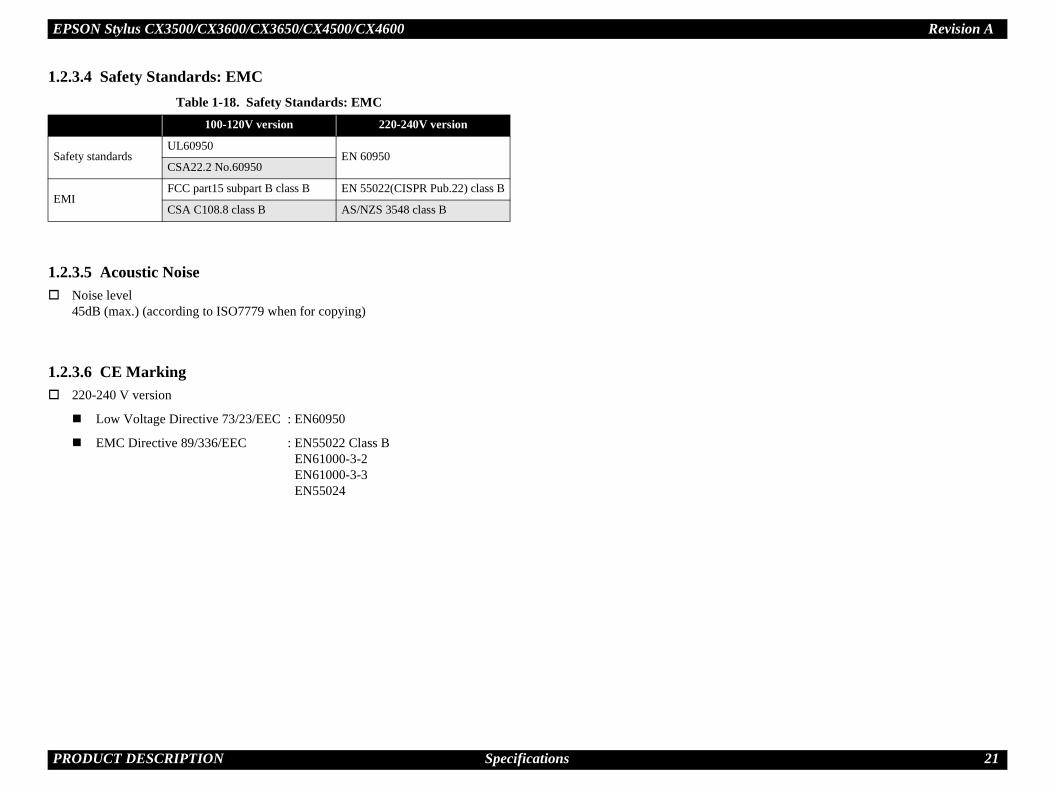
.2.3.4 Safety Standards: EMC
.2.3.5 Acoustic NoiseNoise level45dB (max.) (according to ISO7779 when for copying)
.2.3.6 CE Marking220-240 V version
Low Voltage Directive 73/23/EEC : EN60950
EMC Directive 89/336/EEC : EN55022 Class BEN61000-3-2EN61000-3-3EN55024
Table 1-18. Safety Standards: EMC100-120V version 220-240V version
Safety standardsUL60950
EN 60950CSA22.2 No.60950
EMIFCC part15 subpart B class B EN 55022(CISPR Pub.22) class B
CSA C108.8 class B AS/NZS 3548 class B
EPSON Stylus CX3500/CX3600/CX3650/CX4500/CX4600 Revision A
P 22
1.Thfol
1.
9. USB pin Assignment
X4600)
X3600/CX3650)
M
C
C
C
ector pin assignment and signalsFunction description
Cable power. Max. power consumption is 2mA.
Data
Data, pull up to +3.3V via 1.5K ohm resistor.
Cable ground
21. Endpoint attributeddress Endpoint Type Linked Interface
Bulk InScanner
Bulk Out
Bulk InPrinter
Bulk Out
Bulk InCard
Bulk Out
Pin #1
Pin #4
RODUCT DESCRIPTION Interface
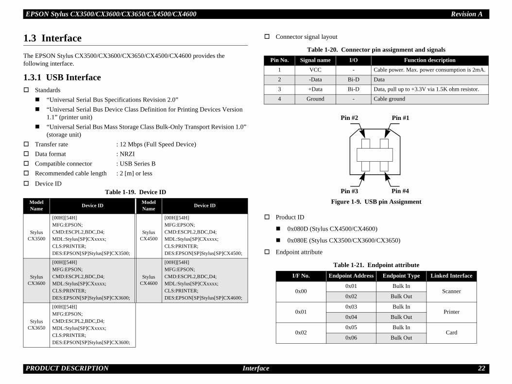
3 Interfacee EPSON Stylus CX3500/CX3600/CX3650/CX4500/CX4600 provides the lowing interface.
3.1 USB InterfaceStandards “Universal Serial Bus Specifications Revision 2.0” “Universal Serial Bus Device Class Definition for Printing Devices Version
1.1” (printer unit) “Universal Serial Bus Mass Storage Class Bulk-Only Transport Revision 1.0”
(storage unit)Transfer rate : 12 Mbps (Full Speed Device)Data format : NRZICompatible connector : USB Series BRecommended cable length : 2 [m] or lessDevice ID
Connector signal layout
Figure 1-
Product ID
0x080D (Stylus CX4500/C
0x080E (Stylus CX3500/C
Endpoint attribute
Table 1-19. Device IDodel
Name Device ID ModelName Device ID
Stylus X3500
[00H][54H]MFG:EPSON;CMD:ESCPL2,BDC,D4;MDL:Stylus[SP]CXxxxx;CLS:PRINTER;DES:EPSON[SP]Stylus[SP]CX3500;
Stylus CX4500
[00H][54H]MFG:EPSON;CMD:ESCPL2,BDC,D4;MDL:Stylus[SP]CXxxxx;CLS:PRINTER;DES:EPSON[SP]Stylus[SP]CX4500;
Stylus X3600
[00H][54H]MFG:EPSON;CMD:ESCPL2,BDC,D4;MDL:Stylus[SP]CXxxxx;CLS:PRINTER;DES:EPSON[SP]Stylus[SP]CX3600;
Stylus CX4600
[00H][54H]MFG:EPSON;CMD:ESCPL2,BDC,D4;MDL:Stylus[SP]CXxxxx;CLS:PRINTER;DES:EPSON[SP]Stylus[SP]CX4600;
Stylus X3650
[00H][54H]MFG:EPSON;CMD:ESCPL2,BDC,D4;MDL:Stylus[SP]CXxxxx;CLS:PRINTER;DES:EPSON[SP]Stylus[SP]CX3600;
Table 1-20. ConnPin No. Signal name I/O
1 VCC -
2 -Data Bi-D
3 +Data Bi-D
4 Ground -
Table 1-I/F No. Endpoint A
0x000x01
0x02
0x010x03
0x04
0x020x05
0x06
Pin #3
Pin #2

EPSON Stylus CX3500/CX3600/CX3650/CX4500/CX4600 Revision A
P 23
1.
1.3
pply voltage
to media that support both 3.3V and 5V.emory card is 500mA. are not supported.
CoFla
Sm
MeSti
MeSti
SD
MuCa
xDCa
ution points when handling the memory card.d and Memory Stick share the same slot, only ted at a time.
edia and xD-Picture Card share the same slot, inserted at a time. card is being accessed, be sure to keep the t's cover closed and do not touch the memory
RODUCT DESCRIPTION Interface
3.2 Standard Card Slots (only for Stylus CX4500/CX4600)
.2.1 Memory card
1.3.2.2 Supported power su 3.3V/5V (both)
3.3V (only)
NOTE 1: 3.3V power is supplied2: Maximum current to m3: 5V type memory cards
Table 1-22. Memory cardMemory card standards Slots Supported memory cards
mpact sh
CF+ and CompactFlash Specification Revision 1.4 compliant
CF Type II slot• Compact Flash
(memory card only)• Microdrive
artMedia SmartMedia Standard 2000 compliant SmartMedia slot Smart Media
(maximum capacity: 128 MB)
mory ck
MemoryStick Standard version 1.3 compliant
Memory Stick/Memory Stick PRO slot
• Memory Stick (maximum capacity: 128 MB, including versions with memory select function)
• MagicGate Memory Stick (maximum capacity: 128 MB, copy protection function is not supported)
• Memory Stick Duo (requires Memory Stick Duo adapter)
mory ck PRO
MemoryStick Standard Memory Stick PRO Format Specifications version 1.0 compliant
• Memory Stick Duo (requires Memory Stick Duo adapter)
• Memory Stick PRO Duo • (requires Memory Stick Duo
adapter)SD Memory Card Specifications / PART1. Physical Layer Specification Version 1.0 compliant SD/MMC slot
• SD (Secure Digital) memory card
• miniSD card (requires SD adapter)
ltiMediard
MultiMediaCard Standard compliant MultiMediaCard
-Picture rd
xD-Picture CardTM Card Specification Version 1.00 compliant
xD-Picture Card slot xD-Picture Card
Note the following ca Since the SD car
one can be inser Since the SmartM
only one can be When a memory
memory card slocard.

EPSON Stylus CX3500/CX3600/CX3650/CX4500/CX4600 Revision A
P 24
1.3
slots is assigned as:
Stick PRO)
is turned onral slots when the power is turned on, the active
riority ranks listed above.nd Memory Stick are both inserted at power-on, slot becomes the active slot.
s turned onom the active slot, the slot with the next-highest slot (if a card has been inserted into it). There is no efore accessing it. If no slots contain any cards, the icro Drive) again becomes the active slot. non-selected slots in any order.
k and CF card are inserted while Smart Media is omes selected (active) once Smart Media is
RODUCT DESCRIPTION Interface
.2.3 Multi-slot operationsOverview
There is only one type of card that can be used to simultaneously access both a connected computer and the direct printing function.
The slots have assigned priority to determine which slot will be accessed first when cards are inserted in several slots at once.
To select a card that has been inserted in a non-active slot, the card in the active slot must first be removed.
• Direct printing:Only the image files in the active slot are valid and have assigned frame numbers. The number of images will not change if a card is also inserted in a non-selected slot.
• Connection to computer (Windows):Only one drive is displayed at a time as a “removable disk” and only the card that is in the active slot can be accessed via the removable disk. A card that has been inserted into a non-selected slot cannot be accessed.
• Connection to computer (Macintosh):Only the card in the active slot can be mounted on the desktop. A card that has been inserted into a non-selected slot cannot be mounted on the desktop.
Details
Access priorityThe access priority among1: CF (Micro Drive)2: Smart Media3: Memory Stick (Memory4: SD (MMC)5: xD-Picture Card
Slot selection when powerIf cards are inserted in seveslot is determined by the pExample: If Smart Media a
the Smart Media
Slot selection after power iWhen a card is removed frpriority becomes the activeneed to re-insert any card bhighest-priority slot (CF MCards can be removed fromExample: If a memory stic
selected, CF becremoved.

EPSON Stylus CX3500/CX3600/CX3650/CX4500/CX4600 Revision A
P 25
1.
1.
1.4
No
No
1.4Thfol
1.4Th
1.4
ed according to “Paper type”, “Paper size” and
3mm copy margin from every side.
ccurs when the print area is set as larger than the , the outer edges of the original image may be
gin on all four sides when printing in order to make age and copy paper.
be used in draft copy mode.
to page” is not selected.
sets the enlarge/reduce scale so that the entire image fits border free area when border free layout is selected. smaller than general card size (approx. 54mm x 86mm), ferent from the one that is defined by each layout.he upper left corner as the origin and any margins that ess occur along the bottom and/or right edge.
pply only to Stylus CX4600.
PlRe
DU(D
1-24. Copy layoutPaper size *3 B&W / Color Layout
A4 (Letter) B&W, Color Standard
m x 15cm (4" x 6") B&W, Color Standard
A4 (Letter),m x 15cm (4" x 6") B&W, Color Small margin
A4 (Letter) B&W, Color Standard
m x 15cm (4" x 6") B&W, Color Standard
A4 (Letter),m x 15cm (4" x 6") B&W, Color Border free
RODUCT DESCRIPTION Stand-alone Copy
4 Stand-alone Copy
4.1 Basic Specifications
.1.1 Supported paper sizes, types and qualities
te : The quality of draft copy is not affected by “Paper type” selection.
te *1: Connected with Paper type.
*2: Paper sizes in parentheses apply only to Stylus CX4600.
.1.2 Zoom functione zoom function provides enlarged or reduced copies of originals. The either of the lowing can be selected from the operation panel.
Actual (The state which “Fit to page” is not selected. It is the power-on default.)The zoom factor is set to 100%.
Fit to pageThis function detects the image size of the original and automatically sets the zoom factor of the copy according to the copy paper's printable area.
.1.3 Number of copies settingis function sets the number of copies. The setting range is 1 to 9 and 100.
.1.4 Maximum copy size216 x 297mm
1.4.1.5 Copy layoutThe following copy layout is providzoom selections.
Standard copyProvided for ordinary use with
BorderFree copyBorder-free printing of copies ocopy paper's size. In such casesomitted in the printed copy.
Small Margins copyThis function sets a 1.5mm marmaximum use of the original im
NOTE: Only “Standard Copy” can
Note *1: Actual is the state that “Fit
*2: “Fit to page” automatically into the printable area or theWhen the original image is the print margins will be difThe image placement uses toccur during the fitting proc
*3: Paper sizes in parentheses a
Table 1-23. Supported paper sizes, types and qualitiesPaper type
Quality *1
Paper size *2
Paper name Panel Indication Paper size Panel
Indication
ain Papercycled Paper
Plain Paper Plain Paper
A4(Letter)
A4(Letter)
RABright Photo PaperURABright Ink Glossy Photo Paper) Photo Paper Photo
Paper
A4 (Letter), 10cm x 15cm
(4" x 6")
A4 (Letter), 10cm x 15cm
(4" x 6")Table
Zoom Paper type
Actual *1
Plain Paper10c
Photo Paper 10c
Fit to page *2
Plain Paper10c
Photo Paper 10c

EPSON Stylus CX3500/CX3600/CX3650/CX4500/CX4600 Revision A
P 26
1.4SecWhstowit
1.
1.4
1.4
copying
ch “Fit to page” is not selected. When “Fit to page” is ll be optimized according to enlarge/reduce scale.
site black will be used in both B&W and color mode.
k and composite black will be used for black printing. sed.
sed for A4 or Letter size printing.
Configuration for copyingScan and Print configuration
Scansolution*1
x S dpi)
Printresolution
(H x V dpi)Dot size MW High
Speed LUT
00 x 300 360 x 360 VSD1 Off On C1
00 x 600 360 x 720 VSD1 On On C1
00 x 600 720 x 1440*4 VSD3 On On C2
00 x 600 720 x 1440*4 VSD3 On On C2
00 x 600 720 x 1440 VSD3 On On C3
00 x 600 720 x 1440 VSD3 On On C3
00 x 100 360 x 120 VSD1 Off On C4
00 x 100 360 x 120 VSD1 Off On C4
RODUCT DESCRIPTION Stand-alone Copy
.1.6 Multiple copies from an originalond and subsequent copies can be printed from an original without scanning. en printing two or more copies, under the following settings the scan data can be
red in the unit's memory so that the second and subsequent copies can be printed hout scanning.
“Draft” mode (monochrome/color)
“Text” mode (monochrome)
4.2 Copy Speed
.2.1 Black Copy SpeedPlain Paper – Draft 12.6 cpm (Copy per minute), Plain Paper – 3.1 cpm
Black e-Memo text A4 size pattern, zoom 100%
The above speed is for the second and subsequent copies (the time between ejection of the first page to ejection of the second page).
.2.2 Color Copy SpeedPlain Paper – Draft 11.6 cpm (Copy per minute)
Color e-Memo text A4 size pattern, zoom 100%
The above speed is for the second and subsequent copies (the time between ejection of the first page to ejection of the second page)
1.4.3 Configuration for
Note *1: “Default” is the state in whiselected, scan resolution wi
*2: With “Photo Paper”, compo
*3: With “Draft”, both real blac“PEC” technology will be u
*4: “PEC” technology will be u
Table 1-25. Copy Mode setting
Paper type B&W /Color
Enlarge / Reduce*1
(%)re(M
Plain PaperB&W 100
(Default) 6
Color 100 (Default) 3
Photo Paper(A4/Letter)
B&W 100 (Default) 6
Color 100 (Default) 6
Photo Paper(smaller than
A4/Letter)
B&W 100 (Default) 6
Color 100 (Default) 6
Draft (Plain paper only)
B&W 100 (Default) 3
Color 100 (Default) 3

EPSON Stylus CX3500/CX3600/CX3650/CX4500/CX4600 Revision A
P 27
1.
1.4Th
No
1-10. Standard copy
aa
Copy
Print area
Copy paper
Print direction
Scan direction
Right side of copy
Right side of original
Original (face down)
Scan area
Scan bed
BM
PL
RL
orner of the original. Normally, this corner is aligned t corner as the reference point.
t position at the top left of the original, which rt position at the top left of the copy. The bottom right is within the print area but varies according to the
RODUCT DESCRIPTION Stand-alone Copy
4.4 Relation between original and copy
.4.1 Standard copye following table shows the relative positioning of the original and copy.
te : Refer to “1.2.1.4 Paper Support” (p.12) for paper width (PW) and paper length (PL).
Figure
Table 1-26. Original (scanner)RW
(readable width)OLM
(out-of-range left margin)RL
(readable length)OTM
(out-of-range top margin)
216 mm (8.5") 1.5 mm ± 1 mm 297 mm (11.7") 1.5 mm ± 1 mm
Table 1-27. Copy (printer)RM LM TM BM
3 mm (0.12") 3 mm (0.12") 3 mm (0.12") 3 mm (0.12")
TM
RM
LM
TopPW
*2*1
OLM
TopRW
OTM
Note *1: This indicates the top left cwith the scan bed's top righ
*2: This indicates the scan starcorresponds to the print stacorner position of the copyenlarge/reduce setting.

EPSON Stylus CX3500/CX3600/CX3650/CX4500/CX4600 Revision A
P 28
1.4Th
No
-11. BorderFree Copy
aa
Copy
Print area
Copy paper
Print direction
Scan direction
Right side of original
Original (face down)
Scan area
Scan bed
BOPL
RL
orner of the original. Normally, this corner is aligned t corner as the reference point.
t position at the top left of the original, which rt position at the top left of the copy. The bottom right ies according to the scale setting in the print area.
Right side of copy
RODUCT DESCRIPTION Stand-alone Copy
.4.2 BorderFree Copye following table shows the relative positioning of the original and copy.
te : Refer to “1.2.1.4 Paper Support” (p.12) for paper width (PW) and paper length (PL).
Figure 1
Table 1-28. Original (scanner)RW
(readable width)OLM
(out-of-range left margin)RL
(readable length)OTM
(out-of-range top margin)
216 mm (8.5") 1.5 mm ± 1 mm 297 mm (11.7") 1.5 mm ± 1 mm
Table 1-29. Copy (printer)RO LO TO BO
2.5 mm (0.09") 2.5 mm (0.09") 3 mm (0.12") 5 mm (0.2")
TO
TopPW
*2*1
OLM
TopRW
OTM
Note *1: This indicates the top left cwith the scan bed's top righ
*2: This indicates the scan starcorresponds to the print stacorner of the print area var
LO

EPSON Stylus CX3500/CX3600/CX3650/CX4500/CX4600 Revision A
P 29
1.4Th
No
12. Small Margins copy
aa
Copy
Print area
Copy paper
Print direction
Scan direction
Right side of copy
Right side of original
Original (face down)
Scan area
Scan bed
BM
PL
RL
orner of the original. Normally, this corner is aligned t corner as the reference point.
t position at the top left of the original, which rt position at the top left of the copy. The bottom right is within the print area but varies according to the
RODUCT DESCRIPTION Stand-alone Copy
.4.3 Small Margins copye following table shows the relative positioning of the original and copy.
te : Refer to “1.2.1.4 Paper Support” (p.12) for paper width (PW) and paper length (PL).
Figure 1-
Table 1-30. Original (scanner)RW
(readable width)OLM
(out-of-range left margin)RL
(readable length)OTM
(out-of-range top margin)
216 mm (8.5") 1.5 mm ± 1 mm 297 mm (11.7") 1.5 mm ± 1 mm
Table 1-31. Copy (printer)RM LM TM BM
1.5 mm (0.06") 1.5 mm (0.06") 1.5 mm (0.06") 1.5 mm (0.06")
TM
RM
LM
TopPW
*2*1
OLM
TopRW
OTM
Note *1: This indicates the top left cwith the scan bed's top righ
*2: This indicates the scan starcorresponds to the print stacorner position of the copyenlarge/reduce setting.

EPSON Stylus CX3500/CX3600/CX3650/CX4500/CX4600 Revision A
P 30
1.
1.
1.5DCpriThFoFil
1.5
1.5Th
Nocan
y this unit is:
(pixels)
(pixels)
f photo data fileso data files. If the amount of photo data to be e memory card, this unit uses file sorting rules to ata in frames numbered from 1 to 999. Although it ith frame numbers over 999 that have been
cification files, the maximum number of frames
tains over 999 photo data files, only files up to 999 “Print index sheet” functions.
tadata in the DCF Version 1.0 format (Exif format,
emory card printing modes, the layout is 80 lain paper or special paper in high-speed print
n the memory, using the photo data files' full-path 00EPSON\EPSN0000.JPG”), and assigned photo umbers are assigned based on this unit's own igned frame numbers do not necessarily match
RODUCT DESCRIPTION Memory Card Print (only for Stylus CX4500/CX4600)
5 Memory Card Print (only for Stylus CX4500/CX4600)
5.1 Basic Specifications
.1.1 File systemF Version 1.0 is the only file system that can be used with this unit's stand-alone
nting functions. Operation is not guaranteed when any other file system is used. e file system used by the card reader function depends on the host's specifications. r a detailed description of the DCF specifications, see the “Design Rule for Camera e System Standard, DCF Version 1.0, JEIDA-49-2-1998”.
.1.2 Media formatMedia must be formatted according to the DCF Version 1.0 standard.DOS FAT formats (FAT12, FAT16) and single partition (basic partition)
.1.3 File formatse file formats supported by this unit are described below.
JPEG files (*.JPG)These are photo data files that comply with the Exif Version 2.1 or Version 2.2 standard.Camera specification files (*.MRK)These are definition files used when in camera specification mode. An “AUTOPRINT.MRK” file whose full path name is no longer than 32 characters is valid.
te, however, any file that is saved in the following directories or their sub-directories not be included as files to be printed.Directories containing system properties or hidden propertiesDirectories that contain any double-byte characters in the directory name“RECYCLED” : Windows directory for deleted files“PREVIEW” : Directories containing CASIO's DSC thumbnail images“SCENE” : Directories containing data for CASIO's DSC Best Shot
function“MSSONY” : Directories containing SONY's DSC e-mail image data, voice
memos, video files, or non-compressed images
1.5.1.4 Valid image sizeThe maximum image size handled b
Horizontal : 120 ≤ X ≤ 4600
Vertical : 120 ≤ Y ≤ 4600
1.5.1.5 Maximum number oThis unit can handle up to 999 photrecorded exceeds the capacity of onsort the photo data into valid photo dis possible to print photo data files wspecified for printing by camera spethat can be specified is 999 frames. If you insert a memory card that conwill be printed by the “Print All” or
1.5.1.6 Thumbnail image daThis unit handles thumbnail image 160 x 120 pixels). During this unit's Index sheet and mthumbnails per sheet (when using pmode).
1.5.1.7 File sortingThis unit stores all photo data files ifile names (for example, “\DCIM\1frame numbers. Since photo frame nproprietary file sorting rules, the assthose indicated by digital cameras.

EPSON Stylus CX3500/CX3600/CX3650/CX4500/CX4600 Revision A
P 31
1.5Th
NO
1.5Thfile
Nomamoinctakpro
1.5PriMo
s settings are listed in the following table. The e total number of options and the number of pages
utively.
le exists in the memory card.
cted as default function of Memory Card Print. But when y card, “Print All / DPOF” will be selected as default and .
-32. List of functions
Layout Paper type Papersize Page/copies
None Plain Paper 1 1
• Standard• Border free
• Plain Paper• Photo Paper
21 to 3
(according to marking)
• Standard• Border free
• Plain Paper• Photo Paper
2 1
• Standard• Border free
• Plain Paper• Photo Paper
2 1 to 99
RODUCT DESCRIPTION Memory Card Print (only for Stylus CX4500/CX4600)
.1.8 File sorting rulesis unit sorts photo data files based on the following prioritization rule.
File name is sorted in ASCII order as full path name.
TE: Sorting results are not guaranteed if two files have matching full-path file names. (Matching full-path file names are not allowed under the DOS specification.)
.1.9 Rules for acquisition of date/time datae following priorities are used to fetch date and time information from photo data s.
1. Date/time data that complies with the standard format (Exif) for digital cameras
2. Date/time data that complies with the DOS standard file system (file time stamps)
3. Fixed values (01/01/1970, 00:00:00)
te that the date/time data assigned to individual photo data files does not necessarily tch the date/time when the photo was actually taken. The photo date/time may be dified due to the digital camera's calendar settings (presence/absence of functions, orrect date/time settings, etc.), processing of the photo data after the photo was en, or subsequent saving of data. In such cases, this unit performs the relevant cessing based on the most recently modified date/time data.
.1.10 Number of sheets which can be printed in totalnting sum total number of sheets presupposes that it is possible to 999 sheets. reover, the printing sum total number of sheets per sheet is possible to 99 sheets.
1.5.2 Functions
1.5.2.1 List of functionsThe memory card print menu and itvalues shown in this table indicate thor copies that can be printed consec
Note "*": It is available only DPOF fi
Note : “Print index sheet” will be seleDPOF file exists in the memorDPOF print can be done easily
Table 1Memory card
printing Mode selection
Print index sheet Print Index Sheet
Print from index sheet
Print From Index Sheet
Print all images Print All / DPOF
DPOF * Print All / DPOF

EPSON Stylus CX3500/CX3600/CX3650/CX4500/CX4600 Revision A
P 32
1.5
lus CX3500/CX3600/CX3650/CX4500.Stylus CX4600.
ll be used for Stylus CX3500/CX3600/CX3650/CX4500.
used for Stylus CX4600.
emory card printing modeode Description Option, setting range, etc.
intingSets print
layout
Fixed in combination with paper type and paper size (refer to “1.5.4 Layout and Paper Type, Paper Size” (p.36))
Fixed Plain Paper
intingSets paper
type Plain Paper or Photo Paper
Fixed A4 or Letter *1
intingSets paper
sizeA4 or 10cm x 15cm *2
Letter or 4" x 6" *3
FixedFixed as 1 page (can vary according to the number of image files)
nting Sets number of printout
1 to 3 (set by the marking to the index sheet)
Sets number of printout 1
Sets number of printout
The number of copies specified via the camera is used. The setting range is 1 to 99 copies (default is 1 copy).
FixedPrints it by the quality of 360 x 720dpi of Plain Paper. Only the Color print is supported.
intingSets print
quality
Fixed according to paper type (refer to “1.5.9 Relation between Paper Type and Quality” (p.40))
RODUCT DESCRIPTION Memory Card Print (only for Stylus CX4500/CX4600)
.2.2 Memory card printing modePrint index sheet printingThis function prints thumbnail images (stored in the memory card) onto an Index Sheet (form) that is marked for selecting images. The combinations of paper types and paper sizes are fixed as follows.
Print from index sheet printingThis function prints selected images onto the sheet output by index sheet printing.
Print all imagesThis function prints all of the image files stored in the memory card. As shown below, the number of printed pages depends on the number of copies to be printed. The settings are described below.
DPOF printingIn this mode, the photo frame numbers previously specified via the camera are printed in the number of pages specified via the camera. Only the paper type and layout are specified on the printer side. If the layout assigned multiple photos per output sheet, photos that have different frame sizes are automatically assigned in the specified number of pages in numerical order (of the specified photo frame numbers). If index print mode was set via the camera, this unit will print in DPOF index layout. (When in DPOF print mode, the mode cannot be switched by writing the print file specification from the host after inserting the memory card.)
Note *1: A4 size will be used for StyLetter size will be used for
*2: A4 or 10cm x 15cm size wi
*3: Letter or 4" x 6" size will be
Table 1-33. MSetting Memory card printing m
Layout (no menu)
• Print from index sheet pr• Print all images• DPOF printing
Paper type
Print index sheet printing
• Print from index sheet pr• Print all images• DPOF printing
Paper size
Print index sheet printing
• Print from index sheet pr• Print all images• DPOF printing
Pages/copies
Print index sheet printing
Print from index sheet pri
Print all images
DPOF printing
Quality
Print index sheet printing
• Print from index sheet pr• Print all images• DPOF printing

EPSON Stylus CX3500/CX3600/CX3650/CX4500/CX4600 Revision A
P 33
1.
3. Sample of index sheet
RODUCT DESCRIPTION Memory Card Print (only for Stylus CX4500/CX4600)
5.3 Index Sheet30 thumbnail images are assigned per index sheet.
There are 3 marking areas for each thumbnail and you can set the number of copies up to 3.
“Paper type” and “Paper size” can be set from the operation panel.
The layout is fixed according to the paper type and it is not indicated on the sheet. (Refer to “1.5.4 Layout and Paper Type, Paper Size” (p.36))
Images are arranged in the Index sheet in ascending order (of image file number). (Refer to “1.5.1.7 File sorting” (p.30) and “1.5.1.8 File sorting rules” (p.31))
Index sheet will be printed from the last page, in descending order. (The sheet containing first thumbnail comes top of printouts.)
The mode transition may occur from “Print index sheet” to “Print from index sheet” when the “Print index sheet” completes successfully.
Figure 1-1

EPSON Stylus CX3500/CX3600/CX3650/CX4500/CX4600 Revision A
P 34
1.5
Set scan area and original
a
can direction
Scan area
RL
t alignment position
Set original face down, with top aligned in the direction of the origin.
Scan bed
Operator's side
RODUCT DESCRIPTION Memory Card Print (only for Stylus CX4500/CX4600)
.3.1 Rules for scanning index sheetsIndex sheet scan range Set index sheet in scanner
• Place the side to be scanned face down relative to the scan bed, as described below.Align the corner of the sheet to the upper left origin point and make sure the sheet is straight. Angled setting of the sheet is allowed as long as the sheet remains within the scan bed's scan range (the maximum angle on the scan bed is about 2.8°).
• The cover must be closed on the original to enable scanning. (This is to prevent any shifting of the position marks while scanning).
• Do not use paper that allows images to “bleed through” to the rear side. (This is to prevent empty bubbles from being filled in by “bleed-through”.)
Set scan area and original
Place the Index Sheet face down with its top edge aligned to the left edge of the scan bed, and with the corner of the paper set to the original's top left position.
Figure 1-14.
Table 1-34. Set scan area and originalRW
(readable width)OLM
(out-of-range left margin)RL
(readable length)OTM
(out-of-range top margin)
216 mm (8.5") 1.5 mm ± 1 mm 297 mm (11.7") 1.5 mm ± 1 mm
S
OLM
RW
OTM
Original's top lef
First pixel

EPSON Stylus CX3500/CX3600/CX3650/CX4500/CX4600 Revision A
P 35
1-15. Symbols check
6. OK/NG mark samples
N
1
2
3
4
5
2
3
3 1 2 3
3 1 2 3
RODUCT DESCRIPTION Memory Card Print (only for Stylus CX4500/CX4600)
Basic specifications for scanning of index sheets
Scanning rules for index sheetCheck if following symbols are found or not.
• When two or three marks of one image are filled, larger number will be used for the number of copies. (ex. 1 and 3 are filled, number of copies is 3.)
• When the optional “ALL” mark is filled, all images in the sheet will be printed one by one regardless of each image mark is filled or not.
• Index sheet error will be caused when any of image mark or “ALL” mark is not filled.
• Index sheet error will be caused when “Left top triangle”, “Right top EPSON” and “Block codes” are not found correctly due to something like smear.
• Place the index sheet so that the “Left top triangle” can meet the left top corner of the scanner.
<OK/NG mark samples>• More than half part of the mark should be filled.• Outside of each mark should not be filled excessively.
Errors during scanning or printing of index sheets• Stops scanning and returns to the menu screen if the card is removed while
an index sheet is being scanned or printed.• Index sheet error (No index sheet) is displayed if the sheet cannot be
scanned because it is dirty, set backwards, etc.• Index sheet error (Incorrect marking) is displayed if the image bubbles
cannot be read because they are not filled in correctly.• Index sheet error (Incorrect card) is displayed if, after printing an index
sheet, you try to print from a non-matching memory card, such as a different (replacement) card or a re-edited version of the same card.
Figure
Figure 1-1
Table 1-35. Symbols checko. Symbols Usage
Left top triangle (1) Left reference position
Right top “O” of EPSON (1) Right reference position
Right top block codes (36) Sheet information (memory card ID, page)
Optional mark of “ALL” (1) Determines whether or not to print all images in the sheet
Image marks (3x30) Determines whether or not to print each image up to 3 copies. Left most is 1, center is 2 and right most is 3.
1
4
5
1 2
1 2
OK patterns
NG patterns

EPSON Stylus CX3500/CX3600/CX3650/CX4500/CX4600 Revision A
P 36
1.Th
No
1.Th
na means of coordinating photo data with the types t. This function is always activated so that printing photo frames. low.
oto to be printed are matched in length along one he perpendicular side to fit the frame on that side. fit within the photo frame is trimmed away (not
17. Trimming Function
1-
se parts are trimmed.
Photo frame (print area)
mple in which the photo data is aligned vertically
mple in which the photo data is aligned me.
Photo frame (print area)
RODUCT DESCRIPTION Memory Card Print (only for Stylus CX4500/CX4600)
5.4 Layout and Paper Type, Paper Sizee layout/paper type and size combinations that can be selected are listed below.
te 1: A4 or 10cm x 15cm size will be used for Stylus CX3500/CX3600/CX3650/CX4500.
2: Letter or 4" x 6" size will be used for Stylus CX4600.
5.5 Optionse functions below will be available by marking to options on the index sheet.
Prints all photos one by one shown on the index sheet.
1.5.6 Trimming FunctioA trimming function is provided as of photo frames handled by this uniphoto data is in shapes that fit theseThis function is described briefly beThe printed photo frame and the phside and the photo is resized along tAny part of the photo that does not printed).
Figure 1-
Table 1-36. Layout and Paper Type, Paper SizeLayout Paper type Paper size Description
Border free Photo Paper• A4, 10cm x15cm *1
• Letter, 4" x 6" *2Prints with no margins along top, bottom and both sides
up with borders Plain Paper• A4, 10cm x15cm *1
• Letter, 4" x 6" *2Prints with 3 mm margins along top, bottom and both sides
20-up —10cm x15cm *1
4" x 6" *2
Prints 20 frames per page, laid out in 5 columns and 4 rows (For DPOF index print only)
80-up —A4 *1
Letter *2
Prints 80 frames per page, laid out in 10 columns and 8 rows (For DPOF index print only)
The
The image below shows an exawith the photo frame.
The image below shows an exahorizontally with the photo fra
These parts are trimmed.

EPSON Stylus CX3500/CX3600/CX3650/CX4500/CX4600 Revision A
P 37
1.
ThdestheThpripixnumprishaHohor(N(podig
les for Photo Frame Numbers and Rotation
1 2 3 4 5 6 7 89 10 11 12 13 14 15 16
17 18 19 20 21 22 23 24
25 26 27 28 29 30 31 3233 34 35 36 37 38 39 4041 42 43 44 45 46 47 4849 50 51 52 53 54 55 56
57 58 59 60 61 62 63 6465 66 67 68 69 70 71 72
73 74 75 76 77 78 79 80
> <1 sheet with borders>
<80-up>
RODUCT DESCRIPTION Memory Card Print (only for Stylus CX4500/CX4600)
5.7 Assignment Rules for Photo Frame Numbers and Rotation
e rules concerning photo frame numbers that are referred when assigning photos are cribed below. The numbers shown in each diagram and photo frame below indicate photo frame numbers used for various types of layout. e direction of the number shown in each photo frame matches the direction of the nted photo to which the horizontal photo data was allocated. When there are more els vertically than horizontally, the vertical photo data is allocated instead, and the
ber shown in the figure below is then rotated 90° before being printed. In Index nting mode, the numbers are printed as they are shown below, regardless of the pe of the photo data. wever, when the photo data has an equal number of pixels vertically and izontally the photos are printed without rotation, regardless of the layout.
ote: the vertical photo data refers to when the photo data file itself is set for a vertical rtrait) orientation. Photo data is defined as the vertical photo data if it is taken by a ital camera with a portrait position detecting function.)
Figure 1-18. Assignment Ru
Top edge
<Border-free
<20-up>

EPSON Stylus CX3500/CX3600/CX3650/CX4500/CX4600 Revision A
P 38
1.
1.5
No
-20. 1-up with borders
e used for Stylus CX3500/CX3600/CX3650/CX4500.
ed for Stylus CX4600.
10
-38. 1-up with borders (unit: mm (inch))C D E F G H
04.00 291.00 3.00 3.00 3.00 3.00
95.60 146.40 3.00 3.00 3.00 3.00
09.908.26)
273.40(10.76)
3.00(0.12)
3.00(0.12)
3.00(0.12)
3.00(0.12)
95.603.76)
146.40(5.76)
3.00(0.12)
3.00(0.12)
3.00(0.12)
3.00(0.12)
Printable area
CA
F
RODUCT DESCRIPTION Memory Card Print (only for Stylus CX4500/CX4600)
5.8 Layout Drawings
.8.1 Border free
Figure 1-19. Border free
te 1: A4 or 10cm x 15cm size will be used for Stylus CX3500/CX3600/CX3650/CX4500.
2: Letter or 4" x 6" size will be used for Stylus CX4600.
1.5.8.2 1-up with borders
Figure 1
Note 1: A4 or 10cm x 15cm size will b
2: Letter or 4" x 6" size will be us
Table 1-37. Border free (unit: mm (inch))Paper type A B C D E F G H
A4 *1 210.00 297.00 215.08 305.04 2.54 2.54 2.96 5.08
cm x 15cm *1 101.60 152.40 106.68 160.53 2.54 2.54 2.96 5.08
Letter *2 215.90(8.50)
279.40(11.00)
220.98(8.70)
287.53(11.32)
2.54(0.10)
2.54(0.10)
2.96(0.12)
5.08(0.20)
4" x 6" *2 101.60(4.00)
152.40(6.00)
106.68(4.20)
160.53(6.32)
2.54(0.10)
2.54(0.10)
2.96(0.12)
5.08(0.20)
Paper
AC
FEG
H
BD
Printable area
Table 1Paper type A B
A4 *1 210.00 297.00 2
10cm x 15cm *1 101.60 152.40
Letter *2 215.90(8.50)
279.40(11.00)
2(
4" x 6" *2 101.60(4.00)
152.40(6.00) (
EG
H
DB

EPSON Stylus CX3500/CX3600/CX3650/CX4500/CX4600 Revision A
P 39
1.5
Not
gure 1-22. 80-up
ll be used for Stylus CX3500/CX3600/CX3650/CX4500.
used for Stylus CX4600.
P
10cable 1-40. 80-up (unit: mm (inch))
D E F G H I
20.00 2.00 5.00 18.00 62.00 106.00
20.07(0.79)
6.10(0.24)
6.10(0.24)
6.35(0.25)
58.67(2.31)
111.00(4.37)
M N O P Q
76.00 126.00 176.00 226.00 26.00
64.26(2.53)
116.59(4.59)
168.91(6.65)
221.23(8.71)
119.4(0.47)
JA
K
D
E C
F
HI
RODUCT DESCRIPTION Memory Card Print (only for Stylus CX4500/CX4600)
.8.3 20-up
Figure 1-21. 20-up
e 1: A4 or 10cm x 15cm size will be used for Stylus CX3500/CX3600/CX3650/CX4500.
2: Letter or 4" x 6" size will be used for Stylus CX4600.
1.5.8.4 80-up
Fi
Note *1: A4 or 10cm x 15cm size wi
*2: Letter or 4" x 6" size will be
Table 1-39. 20-up (unit: mm (inch))aper type A B C D E F G H I J K L
m x 15cm *1 101.60 152.40 20.00 20.00 6.10 6.30 19.80 20.30 3.00 3.00 89.30 112.30
4" x 6" *2 101.60(4.00)
152.40(6.00)
20.00(0.79)
20.00(0.79)
6.10(0.24)
6.30(0.25)
19.80(0.78)
20.30(0.80)
3.00(0.12)
3.00(0.12)
89.30(3.52)
112.30(4.42)
KA
FEG
H
LB
J
J
J
J
D
I I I C
TPaper type A B C
A4 *1 210.00 297.00 20.00
Letter *2 215.90(8.50)
279.40(11.00)
20.07(0.79)
Paper type J K L
A4 *1 150.00 18.00 26.00
Letter *2 163.32(6.43)
6.35(0.25)
11.94(0.47)
GL
Q
M
B
N
O
P
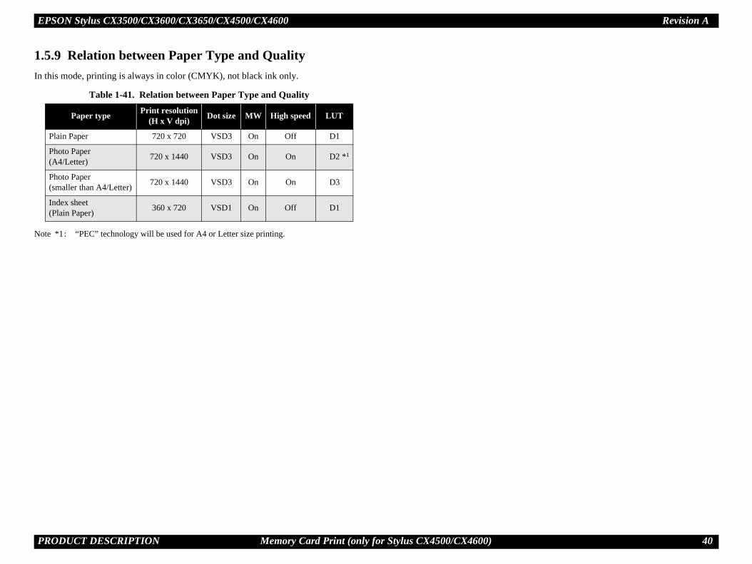
EPSON Stylus CX3500/CX3600/CX3650/CX4500/CX4600 Revision A
P 40
1.In
No
RODUCT DESCRIPTION Memory Card Print (only for Stylus CX4500/CX4600)
5.9 Relation between Paper Type and Qualitythis mode, printing is always in color (CMYK), not black ink only.
te *1: “PEC” technology will be used for A4 or Letter size printing.
Table 1-41. Relation between Paper Type and Quality
Paper type Print resolution(H x V dpi) Dot size MW High speed LUT
Plain Paper 720 x 720 VSD3 On Off D1
Photo Paper(A4/Letter) 720 x 1440 VSD3 On On D2 *1
Photo Paper(smaller than A4/Letter) 720 x 1440 VSD3 On On D3
Index sheet(Plain Paper) 360 x 720 VSD1 On Off D1

EPSON Stylus CX3500/CX3600/CX3650/CX4500/CX4600 Revision A
P 41
1.
1.ThvarAll
No
Rebut
g 7-segment LED and 8 or 11 LEDs, which are
4600de is selected, those LEDs are turned off.tter and 4"x6" are for North and South America, and A4 s.ceeding, this LED is blinking.ode is selected, those LEDs are turned off.
LED will be turned off while printing or scanning by PC.e card slot, not on the control panel.
Po
In
M
C
Pa
Pa
Fi
B
C
St
le 1-43. IndicatorsFunction
d-by. Blink while some operation is proceeding.
k while some error or warning is occurring.
some ink is out. Blink when some ink is near empty or rtridge exchanging procedure.
them while some memory card print function showing dy or proceeding.
heet
ndex Sheet
POF
ber of copies, or some error codes in error status.
y in low power panel status.
them showing which paper type below is selected.
them showing which paper size below is selected.
*2
6" *2
“Fit to Page” function is effective in copy mode.
available memory card is in a slot. Blink when the card.
RODUCT DESCRIPTION Control Panel
6 Control Panel
6.1 Buttonse control panel contains following 9 or 10 buttons, which are used to set and execute ious operations. of them are non-lock type buttons.
te *1: Only for Stylus CX4500/CX4600
*2: B&W means “Black and White”.
fer to “1.6.3.1 Stand-alone Copy / Memory Card Print” (p.43) for details about each ton.
1.6.2 IndicatorsThe control panel contains followinused to indicate various status.
Note *1: Only for Stylus CX4500/CXWhen Standalone Copy mo
*2: Depending on its market. Leand 10x15 are for other area
*3: When DPOF printing is pro*4: When Memory Card Print m*5: All LEDs except for Power *6: This LED is located near th
Table 1-42. ButtonsButton Function
wer Button Execute turning on/off this unit.
k Button Execute exchanging ink cartridges or head cleaning.
emory Card Button *1 Make transition from “Copy mode” to “Memory Card mode” and selects one of card print mode.
opy Button Make transition from “Memory Card mode” to “Copy mode” and sets number of copies.
per Type Button Select paper type.
per Size Button Select paper size.
t to Page Button Alternate zoom of “Fit to page” and default (actual; 100%).
&W Start Button *2 Start monochrome copy.
olor Start Button Start card print or color copy.
op Button Stop job of copying or printing or sometimes work as shift button.
TabLED
Power LED [Green] *5 Light at stan
Error LED [Red] Light or blin
Ink LED [Red] Light when in the ink ca
Memory Card LED 1-3 *1
Light one ofbelow is rea
1st [Green] Print Index S
2nd [Green] Print From I
3rd [Green] *3 Print All / D
7-seg. LED *4 Indicate num
Decimal Point LED Blinks slowl
Paper Type LED 1,2 Light one of
1st [Green] Plain Paper
2nd [Green] Photo Paper
Paper Size LED 1,2 Light one of
1st [Green] A4 or Letter
2nd [Green] 10x15 or 4"x
Fit to Page LED [Green] Light when
Card Access LED [Green] *6
Light when accessing to

EPSON Stylus CX3500/CX3600/CX3650/CX4500/CX4600 Revision A
P 42
ol panel (Stylus CX4500/CX4600)
Power LED
Error LEDInk LED
Memory Card LED 1-3
7-seg. LED
Paper Type LED 1,2Paper Size LED 1,2Fit to Page LED
<Stylus CX4600>
RODUCT DESCRIPTION Control Panel
Figure 1-23. Control panel (Stylus CX3500/CX3600/CX3650)Figure 1-24. Contr
Power Button
Ink Button
Copy Button
Paper Type Button
Paper Size Button
Fit to Page Button
B&W StartButton
Color StartButton
Stop Button
Power LED
Error LEDInk LED
7-seg. LED
Paper Type LED 1,2Paper Size LED 1,2Fit to Page LED
Power Button
Ink Button
Memory CardButton
Copy Button
Paper Type Button
Paper Size Button
Fit to Page Button
B&W StartButton
Color StartButton
Stop Button
<Stylus CX4500>

EPSON Stylus CX3500/CX3600/CX3650/CX4500/CX4600 Revision A
P 43
1.
1.6Th ing table.
Print (only for stylus CX4500/CX4600)
Po
In ithout I/C. CR moves in the order of Cyan, Magenta, Yellow,
In(Hse
or, memory card error, index sheet error, PG error.
MBu(oCX
nt” function.
ange to “Print From Index Sheet”, and change paper type and er size to the one last set in “Print From Index Sheet” or “Print / DPOF”.ange to “Print All / DPOF”.ange to “Print Index Sheet”, and change paper type and paper to “Plain Paper” and “Letter (or A4)”. error, index sheet error, PG error.
Co
rd print” mode to “Stand-alone copy” mode and set number of
leaning head, stopping printing or copying, exchanging I/C, or card error, index sheet error, PG error.
Pa
er” and “Photo Paper” which will be used in “Print From Index
then it is fixed to “Plain Paper”.
RODUCT DESCRIPTION Control Panel
6.3 Operations
.3.1 Stand-alone Copy / Memory Card Printe functions of this unit caused by each button in stand-alone copy mode or memory card print mode are described in the follow
Table 1-44. Operations
ButtonFunction
Stand-alone Copy Memory Card
wer Button • Turn on or off this unit.
k Button
• Start or advance ink cartridge (I/C) exchanging procedure. Case
[All inks are enough.] Move carriage (CR) to I/C exchange position. [Ink low, Ink out, Without I/C error] Move CR to each color's ink check position if that color's I/C is ink low or ink out or w
Black. [CR is in some color's ink check position.] Move CR to next color's ink check position or I/C exchange position. [CR is in I/C exchange position.] Move CR to standby position.
k Buttonolding over 3 c.)
• Start cleaning head procedure.• Invalid while printing, scanning, cleaning head, stopping printing or copying, exchanging I/C, or in error status except for paper out err
emory Card tton
nly for Stylus 4500/CX4600)
• Make transition from “Stand-alone copy” mode to “Memory card print” mode and select and light “Print Index Sheet”, or “Print All / DPOF” if DPOF file exists in the card.
• Turn off both 7-seg. LED and “Fit to Page” LED.• Select “Plain Paper” and “Letter (or A4)”
• Change to next “Memory card pri Case
[Print Index Sheet] ChpapAll
[Print From Index Sheet] Ch [Print All / DPOF] Ch
size• Invalid while printing, scanning, cleaning head, stopping printing or copying, exchanging I/C, or in error status except for memory card
py Button
• Set number of copies incrementally and indicate it on 7-seg. LED. Case
[1 to 8] Add 1 and the number becomes 2 to 9. [9] Indicate “-”, which means 100 copies. [-] Reset to “1”.
• Make transition from “Memory cacopies to “1”.
• Invalid while printing, scanning, cin error status except for memory
per Type Button
• Alternate paper type of “Plain Paper” and “Photo Paper”. • Alternate paper type of “Plain PapSheet” or “Print All / DPOF”.
• Invalid in “Print Index Sheet”, and• Invalid while printing, scanning, cleaning head, stopping printing or copying, exchanging I/C, or in error status.

EPSON Stylus CX3500/CX3600/CX3650/CX4500/CX4600 Revision A
P 44
Pa
A4)” and “4"x6" (or 10x15)” which will be used in “Print DPOF”. then it is fixed to “Letter (or A4)”.
Fiys turned off in this mode.
B&
status.was suspended by PG error.Print from index sheet”.
Co
Sheet” to “Print From Index Sheet” when “Print Index Sheet” error or “STOP” operation.
atus when incompatible memory card is inserted or no
St
B&wi —
Cowi —
Print (only for stylus CX4500/CX4600)
RODUCT DESCRIPTION Control Panel
per Size Button
• Alternate paper size of “Letter (or A4)” and “4"x6" (or 10x15)”. • Alternate paper size of “Letter (orFrom Index Sheet” or “Print All /
• Invalid in “Print Index Sheet”, and• Invalid while printing, scanning, cleaning head, stopping printing or copying, exchanging I/C, or in error status.
t to Page Button• Alternate “Fit to Page” status and turn on or off the “Fit to Page” LED.• Invalid while printing, scanning, cleaning head, stopping printing or copying, exchanging I/C, or
in error status.
• Invalid. “Fit to Page” LED is alwa
W Start Button
• Start monochrome copy.• Invalid while printing, scanning, cleaning head, stopping printing or copying, exchanging I/C, or
in ink out error.• Move to PG error status when platen gap is large. But when this button is pressed again in that
status, that print will start.
• Invalid but for clearing some error• Clear PG error and start print that • Clear index sheet error and start “
• Load paper in paper out error or double feed error and eject paper in paper jam error.
lor Start Button
• Start color copy. • Start memory card print.• Make transition from “Print Index
finishes successfully, without any• Invalid with no card in slots.• Move to memory card error st
images found in the card.• Invalid while printing, scanning, cleaning head, stopping printing or copying, exchanging I/C, or in ink out error.• Load paper in paper out error or double feed error and eject paper in paper jam error.• Move to PG error status when platen gap is large. But when this button is pressed again in that status, that print will start.
op Button
• Stop job of copying or printing and reset the number of copies to the beginning. • Stop job of copying or printing.• Eject paper when paper exists or may exist in the paper path.• Invalid while PC scanning, cleaning head and exchanging I/C.• Clear some of error status.
W Start Button th Stop Button
• Start draft monochrome copy when “Plain Paper” and “Letter (or A4)” are selected.• Invalid while printing, scanning, cleaning head, stopping printing or copying, exchanging I/C, or
in ink out error, or without “Letter” or “A4” is selected.• Move to PG error status when platen gap is large.
lor Start Button th Stop Button
• Start draft color copy when “Plain Paper” and “Letter (or A4)” are selected.• Invalid while printing, scanning, cleaning head, stopping printing or copying, exchanging I/C, or
in ink out error, or without “Letter” or “A4” is selected.• Move to PG error status when platen gap is large.
Table 1-44. Operations
ButtonFunction
Stand-alone Copy Memory Card

EPSON Stylus CX3500/CX3600/CX3650/CX4500/CX4600 Revision A
P 45
1.6
Ththe
1.6WistaconThscaTh
minutes while the printer and scanner unit are in the low power panel mode in which power s. y pushing any switch or printing/scanning by PC.
print only with this unit. Left ink quantity of each color
s unit while depressing Ink Button. After printing ary standby status. n is below.
5. Nozzle check pattern
C
C
Trpo
Rlo
7. Adjust lever function
Function
layed with 7-seg.LED for about 3 seconds just after the hanged to “H: Envelope” position.
layed with 7-seg.LED for about 3 seconds just after the hanged to “L: Cut sheet” position.ror and print job suspended by PG error when the adjust to “L: Cut sheet position” in the PG error status.
2010
4030
6050
8070
90
111
3121
5141
7161
81
2010
4030
6050
8070
90
111
3121
5141
7161
81
2010
4030
6050
8070
90
enta> <Yellow> <Black>
i VSD Large dot
0.212mm (1/120inch)
Q-PIT versionRemaining ink
quantity
RODUCT DESCRIPTION Control Panel
.3.2 Memory Card Insertion/Ejection (only for Stylus CX4500/CX4600)
e functions of this unit caused by memory card insertion or ejection are described in following table.
.3.3 Low Power Panel Modethout any panel operation for 15 minutes while the printer and scanner unit are in ndby status, this unit moves into the low power panel mode in which power sumption for the panel decreases.
is unit recovers from that mode by pushing any button but Power Button or printing/nning by PC. is unit is turned off by pushing Power Button in that mode.
1.6.3.4 Adjust lever functionWithout any panel operation for 15 standby status, this unit moves into consumption for the panel decreaseThis unit recovers from that mode b
1.6.3.5 Nozzle check patternNozzle check pattern can be printedis also printed by the unit of 10%. To activate this function, turn on thithe pattern, this unit moves to ordinThe example of nozzle check patter
Figure 1-2
Table 1-45. Memory Card Insertion/EjectionAction Function
ard Insertion
• Recognize the card and light Card Access LED if it is right.• The LED blinks while memory access occurs to the memory card.• Also the Power LED blinks during the card recognition.• Return from the low power panel mode.
ard Ejection• Turn off Card Access LED.• Stop print job while memory card print is in process and eject paper.• Clear memory card error if memory card is wrong.
Table 1-46. Low Power Panel ModeAction Function
ansition to low wer mode
• Turn off all LEDs except for Power LED and Card Access LED.• Blink Decimal Point LED slowly.• No move in error status except for memory card error, index sheet error
and PG error.• Ejecting of memory card or accessing it by PC has no effect on low
power mode.
ecovery from w power mode
• Recall the panel status as that before moving to low power panel mode.• Inserting or ejecting of memory card or accessing it by PC has no effect
on low power mode.
Table 1-4Adjust lever
status
PG open (Displayed “H”)
• “H” will be dispadjust lever is c
PG close (Displayed “L”)
• “L” will be dispadjust lever is c
• Clear the PG erlever is changed
111
3121
5141
7161
81
2010
4030
6050
8070
90
111
3121
5141
7161
81
<Cyan> <Mag
360dp
32dots
ROMversion

EPSON Stylus CX3500/CX3600/CX3650/CX4500/CX4600 Revision A
P 46
1.6AlipriadjconTopatcan
to adjust while “Letter (or A4)” LED is ON.riate value regarding the printed pattern #3 by
as 1st, 2nd parameters.ch to terminate that adjustment as 1st, 2nd
to adjust while “4"x6" (or 10x15)” LED is ON.riate value regarding the printed pattern #4 by
as 1st, 2nd parameters.ch to terminate that adjustment as 1st, 2nd
ameter adjustment is terminated successfully, the memorized and this unit will be turned off usted value will be effective from next turning on.d values are memorized, all the LEDs except for
l be flashing once.
procedure will be terminated unsuccessfully in ses and no adjustment will be done.ike Paper Out, Paper Jam, PG Open has
re is terminated by pressing Stop Switch.urned off.t has occurred, the procedure can restart from by pressing Color Start Switch. The error ed in advance.
e operation like “exchanging I/C” or “cleaning e done in this mode. turned off automatically when the procedure is ressing Stop Switch and when PG open error d then the adjust lever has been set to close
RODUCT DESCRIPTION Control Panel
.3.6 Head alignment adjustmentgnment adjustments can be made to maintain high print quality during bi-directional nting. This function can be used for basic adjustments. For more precise ustments, we recommend using the head alignment utility that is installed in the nected computer.
activate this function, turn on this unit while depressing Copy mode Switch. The tern will be printed which shows the head alignment at that time, and adjustment be done regarding to that pattern. Following is the sample.
Procedure
Preparation
1. Set A4 or Letter sized paper to the sheet feeder.2. Set PG position is close (L).
Print Pattern
1. Turn on this unit while depressing Copy Switch.2. Alignment adjustment pattern is printed.
Adjust 1st parameter
1. 1st parameter is ready to adjust while “Plain Paper” LED is ON.2. Select the most appropriate value regarding the printed pattern #1 by
pressing Copy Switch. The initial value is “5” indicated on 7-seg. LED and by pressing Copy Switch, the value will change from “1” upto “9” incrementally and cyclically.
3. Press B&W Start Switch to terminate 1st parameter adjustment. Just press that switch as well when the initial value is the most appropriate.
Adjust 2nd parameter
1. 2nd parameter is ready to adjust while “Photo Paper” LED is ON.2. Select the most appropriate value regarding the printed pattern #2 by
pressing Copy Switch. The initial value is “5” indicated on 7-seg. LED and by pressing Copy Switch, the value will change from “1” upto “9” incrementally and cyclically.
3. Press B&W Start Switch to terminate 2nd parameter adjustment. Just press that switch as well when the initial value is the most appropriate.
Adjust 3rd parameter
1. 3rd parameter is ready2. Select the most approp
pressing Copy Switch3. Press B&W Start Swit
parameters.
Adjust 4th parameter
1. 4th parameter is ready 2. Select the most approp
pressing Copy Switch3. Press B&W Start Swit
parameters.
Termination
1. 1st, 2nd, 3rd and 4th paradjusted value will beautomatically. The adj
2. To indicate the adjusteCard Access LED wil
The adjustmentthe following ca1. Some error l
occurred.2. The procedu3. The unit is tWhen Paper Ou“Print Pattern”should be remov
Ink maintenanchead” can not b
This unit will beterminated by phas occurred anposition.
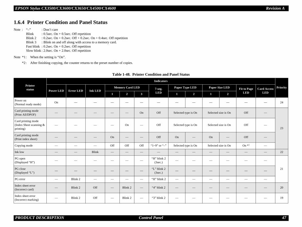
EPSON Stylus CX3500/CX3600/CX3650/CX4500/CX4600 Revision A
P 47
1.No
No
Priorityaper Size LED Fit to Page LED
Card Access LED1 2
Po(N — — — 24
Ca(Pr lected size is On Off —
23
Ca(Inpri
lected size is On Off —
Ca(Pr n — Off —
Co lected size is On On *1 —
Ink — — — 22
PG(D — — —
21PG(D — — —
PG — — —
Ind(In — — — 20
Ind(In — — — 19
RODUCT DESCRIPTION Control Panel
6.4 Printer Condition and Panel Statuste : “–” : Don’t care
Blink : 0.5sec. On + 0.5sec. Off repetitionBlink 2 : 0.2sec. On + 0.2sec. Off + 0.2sec. On + 0.4sec. Off repetitionBlink 3 : Blink on and off along with access to a memory card.Fast blink : 0.2sec. On + 0.2sec. Off repetitionSlow blink : 2.0sec. On + 2.0sec. Off repetition
te *1: When the setting is “On”.
*2: After finishing copying, the counter returns to the preset number of copies.
Table 1-48. Printer Condition and Panel Status
Printerstatus
Indicators
Power LED Error LED Ink LEDMemory Card LED 7-seg.
LED
Paper Type LED P
1 2 3 1 2
wer on ormal ready mode) On — — — — — — — — —
rd printing mode int All/DPOF) — — — — — On Off Selected type is On Se
rd printing mode dex Sheet scanning & nting)
— — — — On — Off Selected type is On Se
rd printing mode int index sheet) — — — On — — Off On — O
pying mode — — — Off Off Off “1~9” or “–” Selected type is On Se
low — — Blink — — — — — — —
open isplayed “H”) — — — — — — “H” blink 2
(3sec.) — — —
close isplayed “L”) — — — — — — “L” blink 2
(3sec.) — — —
error — Blink 2 — — — — “H” blink 2 — — —
ex sheet error correct card) — Blink 2 Off — Blink 2 — “4” blink 2 — — —
ex sheet error correct marking) — Blink 2 Off — Blink 2 — “3” blink 2 — — —

EPSON Stylus CX3500/CX3600/CX3650/CX4500/CX4600 Revision A
P 48
Ind(N — — — 18
Me(Incar
ff Off Off — 17
Po(D — — — 16
Re(reis i
— — — 15
Stocan — — — 14
Thby ff Off Off —
13
Pri ff Off Off —
Co lected size is On On *1 —
12
Ca lected size is On Off —
Ca lected size is On Off —
Ca(Inpri
lected size is On Off —
Ca(Pr n — Off —
Do — — —11
Pa — — —
Ink — — — 10
InkMo — — — 9
Priorityaper Size LED Fit to Page LED
Card Access LED1 2
RODUCT DESCRIPTION Control Panel
ex sheet error o index sheet) — Blink 2 Off — Blink 2 — “2” blink 2 — — —
mory card error compatible memory d)
— Blink 2 Off Blink 2 Blink 2 Blink 2 “1” blink 2 — — O
wer on ata Processing) Blink — — — — — — — — —
ading a memory card cognizing image data) n progress
Blink — — — — — — — — —
pping printing and celling the print job Blink — — — — — — — — —
e scanner is operating a computer Blink — — Off Off Off Off Off Off O
nting by a computer Blink — — Off Off Off Off Off Off O
pying Blink — — Off Off OffNumber of
copies remaining*2
Selected type is On Se
rd printing (DPOF) Blink — — — — On Off Selected type is On Se
rd printing (Print All) Blink — — — — On Off Selected type is On Se
rd printing dex Sheet scanning & nting)
Blink — — — On — Off Selected type is On Se
rd printing int index sheet) Blink — — On — — Off On — O
uble feed — On Off — — — — — — —
per out — On Off — — — — — — —
Sequence Processing Blink — — — — — — — — —
Cartridge Change de Blink 2 Off Blink 2 — — — — — — —
Table 1-48. Printer Condition and Panel Status
Printerstatus
Indicators
Power LED Error LED Ink LEDMemory Card LED 7-seg.
LED
Paper Type LED P
1 2 3 1 2

EPSON Stylus CX3500/CX3600/CX3650/CX4500/CX4600 Revision A
P 49
Inkcar — — —
8CS — — —
Inc — — —
Pa — — — 7
Rereqreqme
min.) On (1min.) On (1min.) — 6
Po(In — — — 5
Ma ink Blink Blink — 4
Fa ink Blink Blink — 3
Fa blink Fast blink Fast blink — 2
Po(Pr ff Off Off — 1
No — — Off —
Me — — On —
Re — — Blink 3 —
PoPa ff Off Off — —
Priorityaper Size LED Fit to Page LED
Card Access LED1 2
RODUCT DESCRIPTION Control Panel
out or No Ink tridge — Off On — — — — — — —
IC error — Off On — — — — — — —
orrect I/C — Off On — — — — — — —
per jam — Blink Off — — — — — — —
set request/Stop uest/Job cancel uest/Various setting mory request
On (1min.) On (1min.) On (1min.) On (1min.)
On (1min.)
On (1min.) On (1min.) On (1min.) On (1min.) On (1
wer on itializing operation) Blink — — — — — — — — —
intenance request Blink On On Blink Blink Blink “E” blink Blink Blink Bl
tal error (Mechanism) Blink Blink Blink Blink Blink Blink “E” blink Blink Blink Bl
tal error (System) Fast blink Fast blink Fast blink Fast blink Fast blink Fast blink Fast “E” blink Fast blink Fast blink Fast
wer off ocessing termination) Fast blink Off Off Off Off Off Off Off Off O
Memory card — — — — — — — — — —
mory card Processing — — — — — — — — — —
ading a memory card — — — — — — — — — —
wer on (Low Power nel Mode) On Off Off Off Off Off Blink slowly
only for D.P. Off Off O
Table 1-48. Printer Condition and Panel Status
Printerstatus
Indicators
Power LED Error LED Ink LEDMemory Card LED 7-seg.
LED
Paper Type LED P
1 2 3 1 2

EPSON Stylus CX3500/CX3600/CX3650/CX4500/CX4600 Revision A
P 50
1.6
s
retained while mode transitioned for each mode while the mode transition from nt” mode or vice versa.
are retained for each mode as default.
ode as default.
are commonly used in “Print From Index OF”.
retained when power is turned offed when the unit's power is off. They are listed ry functions in the table below.
s unit is turned on apart from the mode when it was
retained for each mode as default.
e as default.
Table 1-49. arameter retained in memory Factory setting
Paper Type Plain Paper
Paper Size Letter or A4
oom (The status of Fit to Page) 100% (OFF)
Paper Type Photo Paper
Paper Size 4"x6" or 10x15
RODUCT DESCRIPTION Control Panel
.4.1 Error StatusInk end errorWhen the printer runs out the most amount of the ink of any one color, it indicates ink low and keeps printing. When the printer runs out the whole ink of any color, it stops printing and indicates ink end error. User is then requested to install a new ink cartridge in this state.
Paper out errorWhen the printer fails to load a sheet, it goes into a paper out error.
Paper jam errorWhen the printer fails to eject a sheet, it goes into a paper jam error.
No ink cartridgeWhen the printer detects that ink cartridge comes off, or failed to read or write CSIC data, it goes into this error mode.
Maintenance requestWhen the total amount of ink wasted through cleanings and flushing reaches to the limit, printer indicates this error and stops. In such a case, the absorber in the printer enclosure needs to be replaced with new one by a service person.
Fatal errorCarriage control error.
1.6.5 Memory Function
1.6.5.1 Parameters that areThe following parameters are retain“Copy” mode to “Memory Card Pri
“Paper Type” and “Paper Size”
Zoom is retained for “Copy” m
NOTE: Paper Type and Paper SizeSheet” and “Print All / DP
1.6.5.2 Parameters that areThe following parameters are retainalong with the corresponding memo
Copy mode is selected when thiturned off before.
Paper Type and Paper Size are
Zoom is retained for copy mod
Mode P
Copy
Z
Memory Card Print(only for stylus CX4500/CX4600)

EPSON Stylus CX3500/CX3600/CX3650/CX4500/CX4600 Revision A
P 51
1.Thini
1.
2.
3.
4.
RODUCT DESCRIPTION Control Panel
6.6 Printer Initializationere are four kinds of initialization method, and the following explains each tialization.
Power-on initializationThis printer is initialized when turning the printer power on, or printer recognized the cold-reset command (remote RS command).When printer is initialized, the following actions are performed.(a) Initializes printer mechanism(b) Clears input data buffer(c) Clears print buffer(d) Sets default values
Operator initializationThis printer is initialized when turning the printer power on again within 10 seconds from last power off, or printer recognized the -INIT signal (negative pulse) of parallel interface.When printer is initialized, the following actions are performed.(a) Cap the printer head(b) Eject a paper(c) Clears input data buffer(d) Clears print buffer(e) Sets default values
Software initializationThe ESC@ command also initialize the printer.When printer is initialized, the following actions are performed.(a) Clears print buffer(b) Sets default values
Power-on initialization except I/FThe printer recognized the IEEE 1284.4 “rs” command.When printer is initialized, the following action is performed.(a) Initializes printer mechanism(b) Clears input data buffer(c) Clears print buffer(d) Sets default values except I/F
C H A P T E R
O TING PRINCIPLES
PERA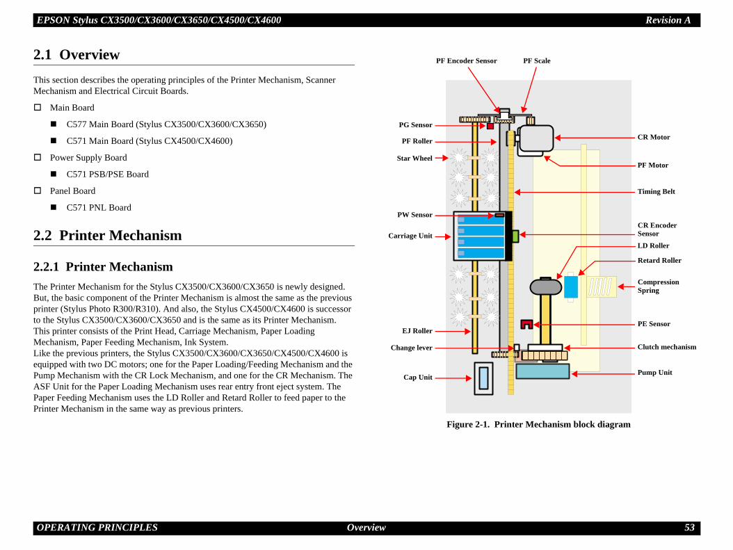
EPSON Stylus CX3500/CX3600/CX3650/CX4500/CX4600 Revision A
O 53
2.ThMe
2.
2.ThBuprito ThMeLikequPuASPapPri
ter Mechanism block diagram
Compression Spring
LD Roller
Retard Roller
Clutch mechanism
PE Sensor
CR Motor
PF Motor
Pump Unit
CR Encoder Sensor
Timing Belt
PF Scale
PERATING PRINCIPLES Overview
1 Overviewis section describes the operating principles of the Printer Mechanism, Scanner chanism and Electrical Circuit Boards.
Main Board
C577 Main Board (Stylus CX3500/CX3600/CX3650)
C571 Main Board (Stylus CX4500/CX4600)
Power Supply Board
C571 PSB/PSE Board
Panel Board
C571 PNL Board
2 Printer Mechanism
2.1 Printer Mechanisme Printer Mechanism for the Stylus CX3500/CX3600/CX3650 is newly designed. t, the basic component of the Printer Mechanism is almost the same as the previous nter (Stylus Photo R300/R310). And also, the Stylus CX4500/CX4600 is successor the Stylus CX3500/CX3600/CX3650 and is the same as its Printer Mechanism. is printer consists of the Print Head, Carriage Mechanism, Paper Loading chanism, Paper Feeding Mechanism, Ink System. e the previous printers, the Stylus CX3500/CX3600/CX3650/CX4500/CX4600 is ipped with two DC motors; one for the Paper Loading/Feeding Mechanism and the
mp Mechanism with the CR Lock Mechanism, and one for the CR Mechanism. The F Unit for the Paper Loading Mechanism uses rear entry front eject system. The er Feeding Mechanism uses the LD Roller and Retard Roller to feed paper to the
nter Mechanism in the same way as previous printers.
Figure 2-1. Prin
Cap Unit
Carriage Unit
PF Roller
EJ Roller
PG Sensor
Star Wheel
PF Encoder Sensor
Change lever
PW Sensor

EPSON Stylus CX3500/CX3600/CX3650/CX4500/CX4600 Revision A
O 54
2.Th460priTh
Thbel
ThamconInk
e Print Head, which plays a major role in printing, (Stylus Photo R300/R310); on-demand method ment). In order to uniform the ejected ink amount, (13-digits code for this Print Head for Stylus /CX4600) which adjusts PZT voltage drive
ad ID pasted on the Print Head into the EEPROM hen replacing the Print Head, the Main Board Unit, e. (Note: there are no resistor arrays to determine nd then, based on the stored Head ID into the s appropriate PZT drive voltage.
nents for the Print Head.
Electric Element. Based on the drive waveform he PZT selected by the nozzle selector IC on the e ink cavity, which has ink stored, to eject the ink plate.
e CSIC chip mounted on the Ink Cartridge. By sumption amount data is red out from the CSIC ption amount data is written into the CSIC chip.
the Print Head surface is called Nozzle Plate.
lled, if any dirt or dust around the cartridge needle , there is a great possibility of causing nozzle clog d alignment failure and dot missing finally. To set under the cartridge needle.
PERATING PRINCIPLES Printer Mechanism
2.2 Print Heade Print Head is the same D4-CHIPS type as the previous SPC (Stylus CX4500/0), and makes it possible to perform economy dot printing and variable dot
nting. e Print Head nozzle configuration is as follows.
Nozzle layout
Black : 90 nozzles x 1 row
Color : 90 nozzles x 3 row/color (Cyan, Magenta, Yellow)
e nozzle layout when viewed from the back surface of the Print Head is shown ow.
Figure 2-2. Nozzle layout
e Print Head has the Electric Poles (CSIC Connectors) to store the ink consumption ount data into the CSIC chip mounted on the Ink Cartridge. By storing the ink sumption amount data, this printer can detect the ink consumption status, such as Low/Out condition.
The basic operating principles of thare the same as the previous printerwhich uses PZT (Piezo Electric Elethe Print Head has its own Head IDCX3500/CX3600/CX3650/CX4500features. So, you are required to store the Heby using the Adjustment Program wthe Printer Mechanism with new onthe Head ID on the Main Board.) AEEPROM, the Main Board generate
Following explains the basic compo
PZTPZT is an abbreviation of Piezogenerated on the Main Board, tPrint Head pushes the top of thfrom each nozzle on the nozzle
Electric poles for CSICThis Electric Poles connects thusing this poles, current ink conchip. And, the latest ink consum
Nozzle PlateThe plate with nozzle holes on
FilterWhen the Ink Cartridge is instais absorbed into the Print Headand disturbance of ink flow, anprevent this problem, a filter is
#A3#A2#A1
BlackCyan Magenta Yellow
2.822(40/360inch)
A row B row C row D row
#A90#A89#A88
#B3#B2#B1
#B89#B88
#B90
#C3#C2#C1
#C89#C88
#C90
#D3#D2
#D89#D88
#D90
#D1
8.467(120/360inch)
2.822(40/360inch)
0.21
17(3
/360
inch
)0.
1411
(2/3
60in
ch)
0.10
7055
(1/3
60in
ch)
Carriage Moving Direction
Pape
r Fe
ed D
irec
tion

EPSON Stylus CX3500/CX3600/CX3650/CX4500/CX4600 Revision A
O 55
2.2Theje
1.
2.
rint Head printing process
0/CX3600/CX3650/CX4500/CX4600 are variable
d to improve the print quality on exclusive paper. as variable dot printing mode used on other and large dot compose this mode. The printing dot t data and this mode enables to output even sharper
E
*
PZT Ink cavity
Nozzle plate
ZT drive voltage
PERATING PRINCIPLES Printer Mechanism
Ink CavityThe ink absorbed from the Ink Cartridge goes through the filter and then is stored temporarily in this tank called “ink cavity” until PZT is driven.
Figure 2-3. Printhead sectional drawing
.2.1 Printing Processis section explains the process which the Printheads of On-Demand inkjet printers ct ink from each nozzle.
Normal state:When the printing signal is not output from the Main Board (C577 Main, C571 Main), or the PZT drive voltage is not applied, the PZT does not change the shape. Therefore, the PZT does not push the ink cavity. The ink pressure inside the ink cavity is kept normal. (refer to Figure 2-4 (p.55): Normal state)
Ejecting state:When the print signal is output from Main Board (C577 Main, C571 Main), the nozzle selector IC located on the Print Head latches the data once by 1-byte unit. Based on the drive waveform (common voltage) generated on the Main Board, the PZT selected by the nozzle selector IC pushes the top of the ink cavity. By this operation, the ink stored in the ink cavity is ejected from nozzles. (refer to Figure 2-4 (p.55): Ejecting state)
Figure 2-4. P
2.2.2.2 Printing MethodThe dot printing systems of CX350dot printing systems.
Variable dot printingThis printing mode is developeThis mode is basically the sameproducts; micro dot, middle dotsize varies according to the prinimage on exclusive paper.
Nozzle selector board
NeedleInk cartridge
Cavity
PZT
Nozzle plate
CSIC Memory chip
lectric poles for CSIC
Head ID for the Print Head is stored to the EEPROM.
Filter
Ink path
Nozzle
P
Normal state
Ejecting state

EPSON Stylus CX3500/CX3600/CX3650/CX4500/CX4600 Revision A
O 56
2.ThEnFo
2.2Th
Cloadv
rent value according to the variation of the CR l load is measured in a CR measurement sequence a power-on or I/C change sequence. A fatal error pplied to the CR drive system.
rrect the drive current value of the CR Motor l load but also the variations of the motor and like. urrent value is used to calculate a heating value, e is reached, wait time is provided per CR path for
5. Carriage Mechanism
A
Carriage UnitCarriage Guide Shaft
CR Encoder SensorPW Sensor
PERATING PRINCIPLES Printer Mechanism
2.3 Carriage Mechanisme Carriage Mechanism consists of Carriage Unit (including the Print Head, CR coder Board and PW Sensor), CR Motor, Timing Belt and CR Scale etc. llowing figure shows you each component for the CR Mechanism.
.3.1 Carriage Mechanisme following DC motor controls the CR Mechanism on this printer.
se loop control based on the CR Motor (DC Motor) and CR Encoder has antages in stabilized print quality.
Heat generation controlUsing low-cost DC motors, this product grasps the variations of the torque constants, coil resistances and power supply voltages of the individual DC motors adequately to carry out heat generation control according to individual differences.
CR variation measurement sequenceThe variations of the torque constant, coil resistance and power supply voltage of the motor are measured in a CR variation measurement sequence when the CR mechanical load is in the initial status and saved into the EEPROM. According to the variations (individual differences) measured in this sequence, the voltage is corrected to make the drive current value constant (without an individual difference).
CR measurement sequenceTo set the appropriate drive curmechanical load, the mechanicaand saved into the EEPROM inwill occur if too much load is a
The above control and sequences coaccording to not only the mechanicaIn addition, the resultant CR drive cand when the specified heating valuprinting.
Figure 2-
Table 2-1. Carriage Motor specificationItems Specifications
Type DC motor with brushes
Drive Voltage 42V (DC) ± 5% (voltage applied to driver)
rmature resistance 28.4 Ω ± 10% (per phase at 25 degrees)
Inductance 20.1mH ± 25% (1KH 1Vrms)
Drive Method PWM, constant-current chopping
Driver IC A6627
CR Motor
Timing Belt
CR Scale

EPSON Stylus CX3500/CX3600/CX3650/CX4500/CX4600 Revision A
O 57
2.2AscurTh
W Detectionsor installed on the Carriage Unit bottom is used to ous sequences.
PW Sensor operating principle.
W Sensor in three places on the right end plane ront Paper Guide every time power is switched on, ed into the EEPROM as threshold values.
n voltage: Paper present
n voltage: Paper absent
med.
n Controliately after the end of paper locating), or during nt or not is detected to prevent off-paper printing ss printing used in a wrong way.
troltart of printing. Also sets the amount of extension g borderless printing.
ontrolr the paper trailing edge during printing.
PERATING PRINCIPLES Printer Mechanism
.3.2 Carriage Home Position Detection in the conventional model, the Carriage Home Position is detected using the drive rent of the CR Motor and the speed/position signal of the CR Encoder. e basic home position detection sequence is as described below.
2.2.3.3 Sequence Used for PThe PW (paper width detection) Sencontrol the printer according to vari
The following briefly describes the
A dark voltage is measured by the P(area without the absorber) of the Fand the measurement values are sav
Threshold value > detectio
Threshold value < detectio
The following sequences are perfor
Paper Left/Right Edge DetectioBefore start of printing (immedprinting, whether paper is preseon the Paper Guide by borderle
Paper Top Edge Detection ConDetects paper leading edge at sfor the paper leading edge durin
Paper Bottom Edge Detection CSets the amount of extension fo

EPSON Stylus CX3500/CX3600/CX3650/CX4500/CX4600 Revision A
O 58
2.Th
tted to the LD roller shaft and the PF roller through mechanism. The Paper loading mechanism plays a F unit to the PF roller. And also, the Paper feeding paper loaded from the ASF unit. The functions of m varies depending on the rotational direction of
otation direction = seen from the left side of the printer.
on path of the PF Motor drive to the LD Roller, the umbers in the following figure show you the order
ction & PF Motor rotational directionCorresponding functions
up and feed a papere Change Lever on the Clutch mechanismse the Change Lever from the Clutch mechanism
7.2
r Gear 36.8
Combination Gear 27.2, 19.2
Spur Gear 16 (Change Lever)
PE SensorLever
Paper
High signal
PaperAbsent
PaperPresent
de view
Low signal4
56
7
PERATING PRINCIPLES Printer Mechanism
2.4 Paper Loading/Feeding Mechanisme following DC motor controls the Paper loading/feeding mechanism on this printer.
The drive of the PF motor is transmigears for the Paper loading/feeding role in loading a paper from the ASmechanism plays a role in feeding athe Paper loading/feeding mechanisthe PF motor as the table below.
Note "*": The PF Motor pinion gear r
Following shows you the transmissiPF Roller and the EJ Roller. (The nof transmission path.)
Figure 2-6. Paper loading/feeding mechanism
Table 2-2. PF Motor specificationsItem Description
Motor type DC motor with brushes
Drive voltage 42V (DC) ± 5% (voltage applied to driver)
Armature resistance 27.5 Ω ± 10% (per phase at 25 degrees)
Inductance 21.4mH ± 25% (1KH 1Vrms)
Driving method PWM, constant-current chopping
Driver IC A6627
Table 2-3. ASF unit funDirections *
Clockwise • Pick • Set th
Counterclockwise • Relea
Spur Gear 2
SpuSpur Gear 13.5 (PF roller)
Spur Gear 30.8
PF Motorpinion gear
Combination Gear 21.24
Left side view
EJ Roller
PE Sensor
PF Scale
Spur Gear 32.4(PF Roller)
Spur Gear 30.8
Spur Gear 36(EJ Roller)
PF Encoder Sensor
PF Roller
Left si
Note : The Clutch gear is molded on the backside of the Spur Gear 36.8 such as Combination gear.
1 2
3
4 2
3
PF Motor

EPSON Stylus CX3500/CX3600/CX3650/CX4500/CX4600 Revision A
59
FIsee
anismists of the Change Lever in the Pump Unit, the utch mechanism) and the ASF Unit. echanism play a major role in the Paper loading
nctiones not have the ASF Home Position Sensor.
ion Sensor, the Change Lever and the Clutch ASF home position. n the Clutch mechanism with the counterclockwise gear, the ASF home position is detected by this ation. In this time, the printer cannot load a paper e of the PF Motor is not transmitted to the LD
ased from the Clutch mechanism with the otor pinion gear, the ASF home position detection paper loading function. Therefore, the printer can ause the drive of the PF Motor is transmitted to LD
ported from the ASF Unit into the printer by the ller.
ase
Lever release
ms mentioned above prepare the Hopper and Paper g operation, and the remaining paper is returned to
61) show you the ASF paper loading sequence and
OPERATING PRINCIPLES Printer Mechanism
or your reference, the top or the end of a paper is usually detected with the PE Sensor. n case that the PE Sensor cannot detect the top of a paper in the paper loading equence, the printer indicates the “Paper Out error”. If the PE Sensor cannot detect the nd of a paper in the paper feeding sequence, the printer indicates the “Paper Jam rror”. As for the details, refer to Chapter 3 “Troubleshooting”.
2.2.4.1 Paper Loading MechThe Paper loading mechanism consHolder Shaft Unit (including the ClThe Change Lever and the Clutch mmechanism as follows.
1. ASF home position detection fuThe ASF Unit on this printer doInstead of the ASF Home Positmechanism is used to detect theWhen the Change Lever is set orotation of the PF Motor pinionlever for the paper loading operfrom ASF Unit because the drivRoller Shaft.
2. Paper loading functionWhen the Change Lever is releclockwise rotation of the PF Mfunction is changed over to theload a paper from ASF Unit becRoller Shaft.
During paper loading, paper is transrotation of the 2 cams of the LD Ro
Cam (Large) : Hopper rele
Cam (Small) : Paper Back
When 1 page paper is loaded, the caBack Lever for the next paper loadinthe standby position.
Figure 2-7 (p.60) and Figure 2-8 (p.the operation of each mechanism.

EPSON Stylus CX3500/CX3600/CX3650/CX4500/CX4600 Revision A
O 60
Wge(riChthefigtootheresdobeMthipucaShLepafro
Thho
When a paper is loaded from the ASF Unit, the Change Lever moves to the front side of the printer with the CW rotation (right side view) of the PF Motor pinion gear and releases the Clutch lever. As the result, the Clutch turns back to the engagement position by the tension force of the Extension Spring 0.143. And, the Clutch gear is engaged with the Clutch lock tooth to transmit the drive of the PF Motor as left figure. In this time, the Change Lever is locked instantaneously by the protrusion on the backside of the Carriage Unit to change over from the ASF home position detection function to the paper loading function surely.
Extension Spring 0.143
er condition
ght side view)
SF home position setting> (CCW) → 13.5 (PF Roller) (CW) → 27.2 (CW) → ) → ar 36.8 (CCW)ight side of the printer
t side
PERATING PRINCIPLES Printer Mechanism
Figure 2-7. ASF paper loading sequence (Step 1, 2)
hen the PF Motor pinion ar rotates CCW direction ght side view), the ange Lever pushes down Clutch lever as right ure and the Clutch lock th is disengaged from Clutch Gear. As the ult, the LD Roller Shaft se not rotate at all cause the drive of the PF otor is not transmitted. In s time, the Hopper is also shed down by the two ms on the LD Roller aft, and the Paper Back ver is set to avoid that pers are slipped down m the paper set position.
is position is the ASF me position.
Step 1 (ASF Home position) Step 2
Hopper & Paper Back Lever condition
LD Roller Shaft
Paper Back Lever
Torsion spring 6.45
LD Roller
Gear rotation direction (Right side view)
Clutchlever
Clutch lock tooth
<PF Motor drive transmission path for ASF home position setting>PF Motor pinion gear (CCW) → Spur Gear 30.8 (CW) → Spur Gear 32.4 (PF Roller) (CCW) → Spur gear 13.5 (PF Roller) (CCW) → Combination Gear 21.24 (CW) → Spur Gear 27.2 (CCW) → Spur Gear 16 (CW) → Change Lever (CW) → Combination Gear 27.2, 19.2 (CCW) → Spur gear 36.8 (CW) * Above transmission pass = seen from the right side of the printer
Hopper release cam
Compression Spring 5.58
ASF Frame
Hopper & Paper Back Lev
Gear rotation direction (Ri
<PF Motor drive transmission path for APF Motor pinion gear (CW) → Spur Gear 30.8Spur Gear 32.4 (PF Roller) (CW) → Spur gearCombination Gear 21.24 (CCW) → Spur GearSpur Gear 16 (CCW) → Change Lever (CCWCombination Gear 27.2, 19.2 (CW) → Spur ge * Above transmission pass = seen from the r
Hopper
Clutch Clutchgear To Fron
Spur Gear 13.5 (PF Roller)
Changelever

EPSON Stylus CX3500/CX3600/CX3650/CX4500/CX4600 Revision A
O 61
TrsttttAdiHtCAwbt
While the LD Roller rotates CCW direction (right side view) continuously, the top of a paper is loaded to the PF Roller. In this rotation, the Hopper returns to the open position and the Paper Back Lever is pushed up by the cam of the LD Roller. In this time, this lever returns papers to the stand-by position in ASF Unit for next paper loading operation. Then, when the rolling LD Roller & the Clutch come at the above “Step1” position, the Clutch lever is locked with the Change Lever again.In this time, the drive of the PF Motor is interrupted and the drive is transmitted only to the PF Roller side for the paper feeding sequence.
ASF Frame
condition
t side view)
home position setting>CW) → 3.5 (PF Roller) (CCW) → (CCW) →
36.8 (CW) side of the printer
PERATING PRINCIPLES Printer Mechanism
Figure 2-8. ASF paper loading sequence (Step 3, 4)
he PF Motor pinion gear otates CCW direction (right ide view), and the drive of he PF Motor is transmitted o the LD Roller Shaft hrough the Clutch lock ooth and the Clutch gear. fter the LD Roller pushes own the Paper Back Lever nto the ASF Frame, the opper is released by the
ension force of the ompression Spring 5.58. nd, a paper is picked up ith the frictional force etween the LD Roller and he Pad Hopper.
LD Roller Shaft
Step 3 Step 4
Hopper & Paper Back Lever condition
Gear rotation direction (Right side view)
Hopper & Paper Back Lever
Gear rotation direction (Righ
<PF Motor drive transmission path for ASF home position setting>PF Motor pinion gear (CCW) → Spur Gear 30.8 (CW) → Spur Gear 32.4 (PF Roller) (CCW) → Spur gear 13.5 (PF Roller) (CCW) → Combination Gear 21.24 (CW) → Spur Gear 27.2 (CCW) → Spur Gear 16 (CW) → Change Lever (CW) → Combination Gear 27.2, 19.2 (CCW) → Spur gear 36.8 (CW) * Above transmission pass = seen from the right side of the printer
<PF Motor drive transmission path for ASFPF Motor pinion gear (CCW) → Spur Gear 30.8 (Spur Gear 32.4 (PF Roller) (CCW) → Spur gear 1Combination Gear 21.24 (CW) → Spur Gear 27.2Spur Gear 16 (CW) → Change Lever (CW) → Combination Gear 27.2, 19.2 (CCW) → Spur gear * Above transmission pass = seen from the right
Compression Spring 5.58
Hopper release cam
1
2
3
Hopper release cam
Paper Back Lever
1
2
3

EPSON Stylus CX3500/CX3600/CX3650/CX4500/CX4600 Revision A
O 62
2.2ThPFAS
1.
2.
smission path for the PF Roller & the Paper Guide Wheel.
F Roller from the ASF Unit in the paper loading otor pinion gear rotates CW direction (left side r & the Paper Guide Roller and the EJ Roller & the & the paper feed sequence.
CW) → Spur Gear 36 (EJ Roller) (CW)
PERATING PRINCIPLES Printer Mechanism
.4.2 Paper Feeding Mechanism e Paper feeding mechanism consists of PF Motor, PF Roller, EJ Roller, PE Sensor, Encoder and PF Scale etc. The Paper feeding mechanism feeds a paper loaded from F Unit by using pairs of rollers.
One pair is the PF Roller and the Paper Guide Roller which is assembled in the Paper Guide Upper Unit. The drive of the PF Motor is transmitted to the Paper Guide Roller through the PF Roller.
Another pair is the EJ Roller and the Star Wheel which is assembled on the EJ Frame Unit. The drive of the PF Motor is transmitted to the Star Wheel through the EJ Roller.
Following figure shows you the tranRoller and the EJ Roller & the Star
The top of a paper is loaded to the Psequence. And then, when the PF Mview), a paper is fed by the PF RolleStar Wheel in the printing operation
Figure 2-9. Paper feeding mechanism
Left side view
PF Motor
PF Roller
Transmission path (left side view)• PF Motor pinion gear (CW) → Spur Gear 30.8 (CCW) → Spur gear 32.4 (PF Roller) (CW)• PF Motor pinion gear (CW) → Spur Gear 30.8 (CCW) → Spur gear 32.4 (PF Roller) (CW) → Spur Gear 30.8 (C
Spur Gear 30.8
PF Motorpinion gear
PF ScaleSpur Gear 32.4(PF Roller)
Spur Gear 30.8
Spur Gear 36(EJ Roller)
PF Encoder SensorPaper guide roller
Star Wheel
EJ Roller

EPSON Stylus CX3500/CX3600/CX3650/CX4500/CX4600 Revision A
O 63
2.Thmefun
No
(CL position) the ink is forcibly absorbed from the Ink Cartridge ump Unit and is ejected to the Waste Ink Pad while e CL position.
(Ink absorption position)e, the negative pressure is decreased and only the ted while the Carriage Unit is in the further right . (the ink is not absorbed from the Ink Cartridge or
he Carriage Unit position for each condition easily.
ystem, the above 2) operation is done outside the iage Unit moves outside the CR home position and nside the Cap.
C
CL position(valve closing condition)
ion Ink absorption position(valve opening condition)
PERATING PRINCIPLES Printer Mechanism
2.5 Ink System Mechanisme Ink System Mechanism consists of Pump mechanism with Carriage lock chanism and Capping mechanism with Wiper mechanism. Following table lists the ction for each mechanism.
te : Like the previous printers (Stylus Photo R300/R310), this printer adopts the valveless cap system. The air valve system used for the previous printer (Stylus COLOR 740) have two functions by the CR position in the capping condition as follows.
1) Valve closing condition By closing the air valve,or the ink cavity by the Pthe Carriage Unit is in th
2) Valve opening conditionBy opening the Air valvink inside the Cap is ejecside than the CL positionthe ink cavity.)
The following shows you t
But, on the valveless cap scapping position. The Carrthe pump absorbs the ink i
Table 2-4. Function for each mechanismMechanism Function
Capping mechanism * This is to cover the surface of the Print Head with the cap in order to prevent the nozzle from increasing viscosity.
Wiper mechanism This is to remove the foreign material and unnecessary ink on the nozzle plate of the Print Head.
Pump mechanism This is to eject the ink from the Ink Cartridge, the ink cavity and the cap to the Waste Ink Pad.
arriage lock mechanism This is to lock the Carriage Unit with the Change Lever while the Carriage Unit is at the home position.
Printing area CR home posit

EPSON Stylus CX3500/CX3600/CX3650/CX4500/CX4600 Revision A
O 64
2.2Thinc
led by the Carriage Unit movement. This operation CL sequence which is to absorb the ink from the the Pump unit. Following figure shows you the ation.
The Carriage Unit moves to the Wiper setting position on the rightmost position of the Cap Frame with keeping the Cap covered.In this time, the hook of the Slider Lock Lever is latched to the dent of the Cap Frame.
When the wiping operation is finished and the Carriage unit moves further to the left side, the hook of the Carriage unit hits to the Slider lock lever. In this time, the Slider lock lever is released and the Cap slider returns to the bottom position completely.(The broken line is the position of the Carriage unit & the Slider lock lever just before being released.)
WlpbSIapSoot
WhLoISr
m position)
PERATING PRINCIPLES Printer Mechanism
.5.1 Capping Mechanisme Capping mechanism covers the Print Head with the Cap to prevent the nozzle from reasing viscosity when the printer is in stand-by state or when the printer is off.
Wiper with the Cap unitThe wiping operation is controlis usually performed with everyink cartridge, the ink cavity by mechanism for the wiping oper
Figure 2-10. Wiper mechanism
hen the Carriage Unit moves to the eft side from the Wiper setting osition, the Cap Unit is pulled back y the tension force of the Extension pring 0.788. n this time, the Cap Unit is utomatically set to the wiping osition because the hook on the lider Lock Lever is latched to dent f the Cap Frame. And, the wiping peration is performed according to he Carriage Unit movement. Wiping position
Step 1
Capping position (CR home position)
hen the Carriage Unit is in the ome position, the hook of the Slider ock Lever is not latched to the dent f the Cap Frame. n this time, the protrusion of the Cap lider Lever does not reach the ightmost position of the Cap Frame.
Step 2
Step 3 Step 4
Protrusion
Latched
Latched
Protrusion of the Carriage Unit
Not latched
Released
Wiper setting position
Released position (Botto

EPSON Stylus CX3500/CX3600/CX3650/CX4500/CX4600 Revision A
O 65
2.2ThwetrathrOnrolPF
No
tion)k Cartridge, the ink cavity and is ejected to the en the Ink Tube is pressed by a roller in the Pump
rview of the Pump Unit mechanism operation.
ion = seen from the right side of the printer.
-11. Pump mechanism
Waste InkPad side
Right side view
pur gear 13.5 (PF Roller) (CW) →
r 27.2nit gear)
13.5 Combination Gear 21.24
PERATING PRINCIPLES Printer Mechanism
.5.2 Pump Unit Mechanisme PF Motor also controls the Pump Unit mechanism (including the Change Lever) as ll as the Paper loading/feeding mechanism. The drive of the PF Motor is always nsmitted to the Pump Unit. (And also, its drive is transmitted to the LD Roller ough the Clutch mechanism & the Change Lever.) this printer, the Pump Unit mechanism including the Change Lever plays a major e expecting the ink eject operation. And, these operations control depending on the Motor rotational direction as the following table below.
te "*": The PF Motor rotational direction = seen from the left side of the printer.
1. Ink eject operation (usual operaThe ink is absorbed from the InWaste Ink Pad from the Cap whUnit.
Following figure shows you the ove
Note : The PF Motor rotational direct
Figure 2
Figure 2-12. PF Motor drive transmission path to the Pump Unit
Table 2-5. PF Motor rotational direction & Ink system mechanismDirections * Functions
Clockwise • Pump release
Counterclockwise • Absorbs the ink• Release the Change Lever from the Clutch mechanism
Cap Unit side
Cap Unit
Pump UnitLeft side view
Transmission Path: PF Motor pinion gear (CW) → Spur Gear 30.8 (CCW) → Spur Gear 32.4 (PF Roller) (CW) → SCombination Gear 21.24 (CCW) → Spur Gear 27.2 (Pump Unit gear) (CW)(Above transmission pass = seen from the right side of the printer)
Spur Gear 30.8
PF Motorpinion gear
Spur Gear 32.4(PF Roller)
Spur Gea(Pump U
Spur Gear (PF roller)

EPSON Stylus CX3500/CX3600/CX3650/CX4500/CX4600 Revision A
O 66
2.
nd the power is turned on for the first time, the Ink Charge to charge the ink inside the ink cavity. completed properly, the printer releases the flag Charge will take about 100 seconds for Stylus
4500/CX4600. If the power is turned off during the l be performed at next power on timing.
X3650/CX4500/CX4600 provides three types of bbles, clogged ink with viscosity or foreign
ed by the Control Panel Operation, the Printer ent Program.
Ink: 0.482g
y the rubber part on the Cap Unit.
ng, and stabilizes ink surface inside the nozzle.
Ink: 1.335g
y the rubber part on the Cap Unit.
ng, and stabilizes ink surface inside the nozzle.
Ink: 3.045g
y the rubber part on the Cap Unit.
ng, and stabilizes ink surface inside the nozzle.
PERATING PRINCIPLES Printer Mechanism
Carriage lock operation by the Change LeverUnlike the previous printer (Stylus COLOR 680), this printer does not have the Carriage Lock Lever with the Wiper.Instead of the Carriage Lock Lever, the Change Lever is set to the front side of the printer while the Carriage Unit is in the CR home position.(As for the detailed mechanism for setting the Change Lever, refer to Figure 2-7 (p.60) Step 2)
2.2.6 Ink Sequence Initial ink charge
After the printer is purchased aprinter must perform the InitialWhen the Initial Ink Charge is inside the EEPROM. Initial InkCX3500/CX3600/CX3650/CXInitial Ink Charge, the CL3 wil
Manual CleaningThe Stylus CX3500/CX3600/Cmanual cleaning to clean air busubstances.The manual CL can be performDriver Utility and the Adjustm
CL1• Ink absorption
Black Ink: 0.161g, Color• Wiping operation
Wipes the nozzle plate b• Flashing operation
Prevents color from mixi
CL2• Ink absorption
Black Ink: 0.445g, Color• Wiping operation
Wipes the nozzle plate b• Flashing operation
Prevents color from mixi
CL3• Ink absorption
Black Ink: 1.015g, Color• Wiping operation
Wipes the nozzle plate b• Flashing operation
Prevents color from mixi

EPSON Stylus CX3500/CX3600/CX3650/CX4500/CX4600 Revision A
O 67
us Photo R300/R310), this printer dose not have or the backup power source for Timer IC. So, this period or cleaning cycle by using the following
er command to the printer before printing. The sed on the PC’s timer and it consists of year, econd. As soon as the printer receives the timer er, the printer stores its command in address OM. Then, it is compared with the latest CL time > and 05<H> in the EEPROM. And, In case that
r the specific period, the printer performs the timer time, the printer stores the timer command in , 07<H> in the EEPROM. nsumed in the timer cleaning. (0.830g of black ink sumed.)
ns are executed for the following reasons.
of printing to eliminate ink viscosity in the Print
g to prevent ink viscosity in the Print Head nozzles
PERATING PRINCIPLES Printer Mechanism
Independently of the printing path after the previous CL, perform manual CL from CL1 to CL3 in order if the cumulative printing timer counter is less than 9min. Only when the cumulative printing timer counter is more than 9min, execute only CL1.Additionally, if the I/C is Ink Low or Out condition, any manual cleaning is prohibited and it is displayed on the LED indicators.
Timer CleaningLike the previous printers (StylLithium battery which is used fprinter manages the printer off method.The Printer Driver sends the timtimer command is generated bamonth, date, hour, minute and scommand from the Printer Driv06<H> and 07<H> in the EEPRwhich is stored in address 04<Hthe timer cleaning period is ovecleaning automatically. In this address 04<H>, 05<H>, 06<H>Maximum 3.32g of the ink is coand 2.490g of color ink are con
FlashingTwo different flushing operatio
Pre-printing flushingThis is done before a start Head nozzles.
Periodic flushingThis is done during printinfrom increasing.
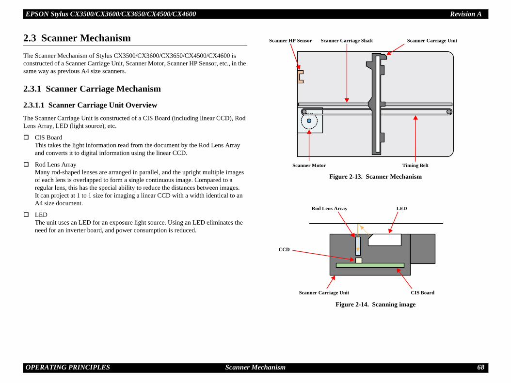
EPSON Stylus CX3500/CX3600/CX3650/CX4500/CX4600 Revision A
O 68
2.Thconsam
2.
2.3ThLe
3. Scanner Mechanism
2-14. Scanning image
Scanner Carriage Unitge Shaft
Timing Belt
LED
CIS Board
PERATING PRINCIPLES Scanner Mechanism
3 Scanner Mechanisme Scanner Mechanism of Stylus CX3500/CX3600/CX3650/CX4500/CX4600 is structed of a Scanner Carriage Unit, Scanner Motor, Scanner HP Sensor, etc., in the e way as previous A4 size scanners.
3.1 Scanner Carriage Mechanism
.1.1 Scanner Carriage Unit Overviewe Scanner Carriage Unit is constructed of a CIS Board (including linear CCD), Rod ns Array, LED (light source), etc.
CIS BoardThis takes the light information read from the document by the Rod Lens Array and converts it to digital information using the linear CCD.
Rod Lens ArrayMany rod-shaped lenses are arranged in parallel, and the upright multiple images of each lens is overlapped to form a single continuous image. Compared to a regular lens, this has the special ability to reduce the distances between images. It can project at 1 to 1 size for imaging a linear CCD with a width identical to an A4 size document.
LEDThe unit uses an LED for an exposure light source. Using an LED eliminates the need for an inverter board, and power consumption is reduced.
Figure 2-1
Figure
Scanner HP Sensor Scanner Carria
Scanner Motor
Rod Lens Array
CCD
Scanner Carriage Unit
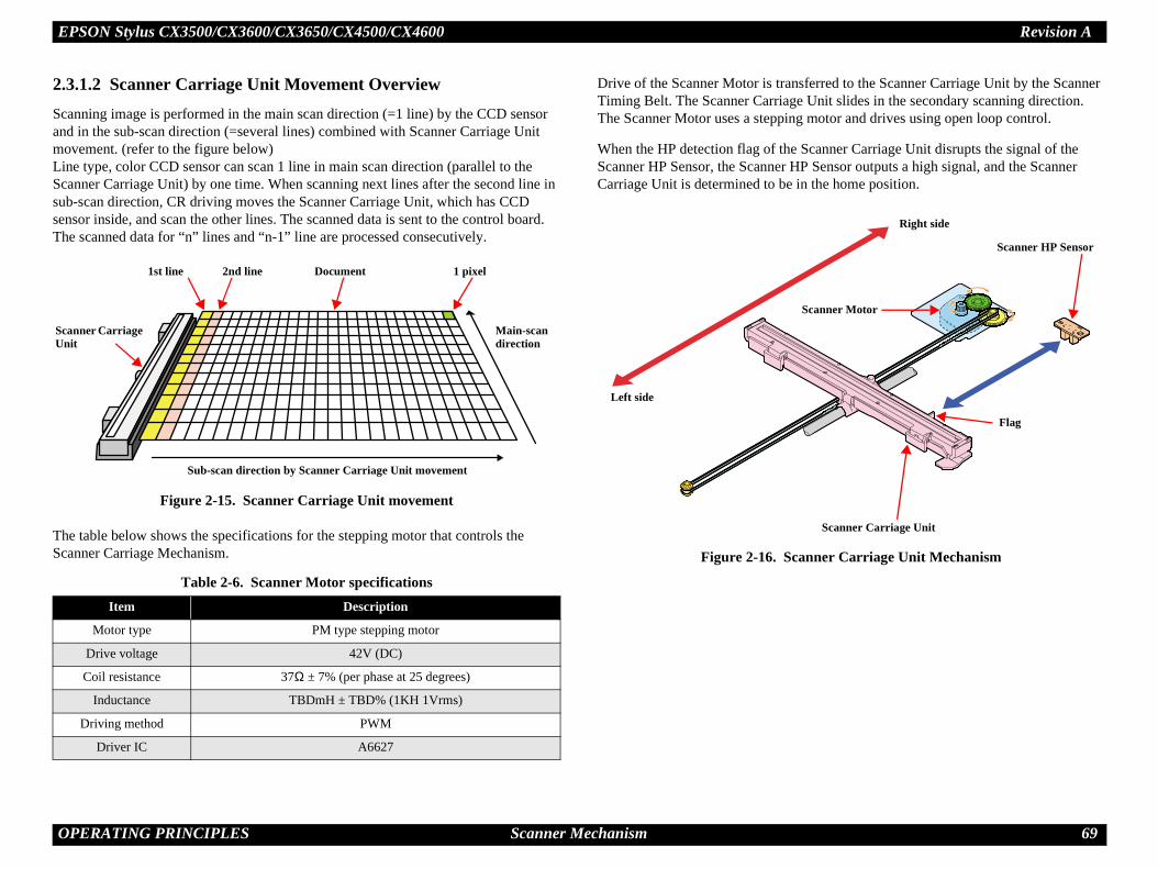
EPSON Stylus CX3500/CX3600/CX3650/CX4500/CX4600 Revision A
O 69
2.3ScaandmoLinScasubsenTh
ThSca
ferred to the Scanner Carriage Unit by the Scanner Unit slides in the secondary scanning direction.motor and drives using open loop control.
canner Carriage Unit disrupts the signal of the Sensor outputs a high signal, and the Scanner the home position.
nner Carriage Unit Mechanism
ScaUn
Right side
Flag
canner Motor
Scanner HP Sensor
Scanner Carriage Unit
PERATING PRINCIPLES Scanner Mechanism
.1.2 Scanner Carriage Unit Movement Overviewnning image is performed in the main scan direction (=1 line) by the CCD sensor in the sub-scan direction (=several lines) combined with Scanner Carriage Unit vement. (refer to the figure below)e type, color CCD sensor can scan 1 line in main scan direction (parallel to the nner Carriage Unit) by one time. When scanning next lines after the second line in -scan direction, CR driving moves the Scanner Carriage Unit, which has CCD sor inside, and scan the other lines. The scanned data is sent to the control board. e scanned data for “n” lines and “n-1” line are processed consecutively.
Figure 2-15. Scanner Carriage Unit movement
e table below shows the specifications for the stepping motor that controls the nner Carriage Mechanism.
Drive of the Scanner Motor is transTiming Belt. The Scanner Carriage The Scanner Motor uses a stepping
When the HP detection flag of the SScanner HP Sensor, the Scanner HPCarriage Unit is determined to be in
Figure 2-16. Sca
Table 2-6. Scanner Motor specificationsItem Description
Motor type PM type stepping motor
Drive voltage 42V (DC)
Coil resistance 37Ω ± 7% (per phase at 25 degrees)
Inductance TBDmH ± TBD% (1KH 1Vrms)
Driving method PWM
Driver IC A6627
1st line 2nd line 1 pixel
Main-scan direction
Sub-scan direction by Scanner Carriage Unit movement
Document
nner Carriage it
Left side
S

EPSON Stylus CX3500/CX3600/CX3650/CX4500/CX4600 Revision A
O 70
2.Thof
NO
ThC5boa
2-17. Electric circuit
Sensors
Head Driver Board
PF Motor
CR Motor
Printer Mechanism
C
ard
Scanner Mechanism
Scanner Motor
CIS Unit
Scanner HP Sensor
Memory Card
Note: Only for C571 Main Board
PERATING PRINCIPLES Electrical Circuit Operating Principles
4 Electrical Circuit Operating Principlese electric circuit of the Stylus CX3500/CX3600/CX3650/CX4500/CX4600 consists the following boards.
Main Board (CPU-ASIC 2 in 1 + Soldering Flash ROM)
Stylus CX3500/CX3600/CX3650 : C577 Main Board
Stylus CX4500/CX4600 : C571 Main Board
Power Supply Board : C571 PSB/PSE Board
TE: CPU and ASIC is integrated as one chip (IC8) on the Main Board.
is section provides operating principles of C577 Main Board, C571 Main Board and 17 PSB/PSE Board. Refer to Figure 2-17 (p.70) for the major connection of the each rds and their roles.
Figure
C577/C571Main Board
C571 PSB/PSEBoard
+42VDPower Off
C577 PNL Bo
EPSON Stylus CX3500/CX3600/CX3650/CX4500/CX4600 Revision A
O 71
2.In osc+4
ACfrethepre+4
d (TBD)
PERATING PRINCIPLES Electrical Circuit Operating Principles
4.1 PSB/PSE Boardthe PSB/PSE Board of Stylus Photo RX420/RX425/RX430, the simulated illating stimulation flyback converter circuit method is used, and it supplies
2VDC to the drive line. The application of the output voltage is described below.
voltage input from AC inlet first goes through filter circuit that removes high quency components and is then converted to DC voltage via the rectifier circuit and smoothing circuit. DC voltage is then lead to the switching circuit and FET Q1 forms the switching operation. By the switching operation of the primary circuit, 2VDC is generated and stabilized at the secondary circuit.
2.4.1.1 C571 PSB/PSE Boar
Table 2-7. Application Of The DC VoltagesVoltage Application
+42VDC• Motors (CR Motor, PF Motor, Scanner Motor)• Print Head common voltage• Print Head nozzle selector 42V drive voltage

EPSON Stylus CX3500/CX3600/CX3650/CX4500/CX4600 Revision A
O 72
2.Th
Thma
of the each main elements on C571/577 Main
2-9. Main ElementsFunction
6MbitFirmware storage
us= 16 bit, 64Mbit DRAMEEPROMDefault settings, backup for all parametersReset functionTimer functionPU mounted on the MAIN board is driven by clock equency 48 MHz, 96MHz and controls the printer and
canner.CR/PF/Scanner motor drive ICDropping 42V line to 5VDropping 3.3V line to 1.5Vropping 5V line to 3.3V
ead drive control HICGenerates head common voltage.
PERATING PRINCIPLES Electrical Circuit Operating Principles
4.2 C571/577 Main Boarde logic circuit of the C571/577 Main Board is composed of the follows;
Logic line (CPU-ASIC 2 in 1, SDRAM, P-ROM and so on)
Motor control/drive circuit (CR Motor, PF Motor, Scanner Motor)
Head control/drive circuit
USB Interface control circuit
Sensor circuit
Combination circuit (RTC circuit, Reset circuit, EEPROM circuit)
e printer mechanism is controlled by the above circuits. Following explains the jor characteristics of this Main Board.
Lithium battery is not mountedUnlike the previous printer (Stylus COLOR 680), the Lithium battery is not mounted on the Main Board.
Adoption of 3.3V/1.5V drive logic circuit componentsThe 5V formed by the Combination Motor Driver (IC9) of C579 Main Board is stepped down to 3.3V by the Regulator (IC10), and it is then used as drive voltage for many elements. In addition, when SPC shifts to low power mode, the 3.3V that was stepped down by the Regulator (IC10) is stepped down to 1.5V by the Combination Motor Driver (IC9) and elements that had been driven by 3.3V are driven by 1.5V for suppression of power consumption.
2.4.2.1 Main ElementsTable 2-9 (p.72) shows the functionBoard.
Table 2-8. 3.3V/1.5V & 5V Drive Components5VDC 3.3/1.5VDC
• Flash ROM (IC5)• SDRAM (IC6)• RTC (IC7)
• CPU-ASIC (IC8)• Motor driver (IC9)• Common driver (IC11)
TableIC Location
Flash ROM IC51•
SDRAM IC6 B
RTC IC7
•
••
CPU-ASIC IC8Cfrs
Motor Driver IC9•••
Regulator IC10 D
Common Driver IC11H•

EPSON Stylus CX3500/CX3600/CX3650/CX4500/CX4600 Revision A
O 73
CN8
CN9
CN10
CR Motor
PF Motor
Scanner
PF Encoder Sensor
PE Sensor
PG Sensor
CN5
CN6Print Head
CN7CR Encoder Sensor
PW Sensor
CSIC Board
PERATING PRINCIPLES Electrical Circuit Operating Principles
Figure 2-18. Block Diagram For The C579 Main Board
CPU-ASIC 2 in 1(IC8)
Data
AddressSDRAM(IC6)
Flash-ROM(IC5)
Card ASIC(IC13)
Card Slot(CN14)
Card Slot(CN15)
RTC(IC7)
CN11CIS Unit
AD Converter
(IC12)
CN12C571 Panel Board
CN13Scanner HP Sensor
USB
CN1C571 PS Board
MotorDriver(IC9)
P1
CN3
CN4
HeadDriver(IC11)
Q9, Q10
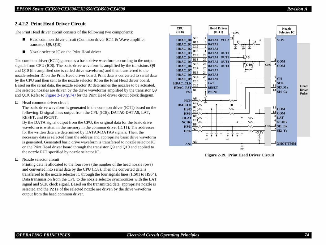
EPSON Stylus CX3500/CX3600/CX3650/CX4500/CX4600 Revision A
O 74
2.4Th
Thsigandnozby BaThand
Print Head Driver Circuit
Nozzle Selector IC+4.2V
Head Drive Pulse
CN6
CN5
VHV
COMCOM
CHSCKSI3_MaSI4_Cy
COMCOMLATNCHGSI1_BkSI2_Ye
XHOT/TMM
2
1123
F1
+3.3V
21
Q9
5
24
9
11
11138642
1
7
13
Q10
F2
PERATING PRINCIPLES Electrical Circuit Operating Principles
.2.2 Print Head Driver Circuite Print Head driver circuit consists of the following two components:
Head common driver circuit (Common driver IC11 & Wave amplifier transistor Q9, Q10)
Nozzle selector IC on the Print Head driver
e common driver (IC11) generates a basic drive waveform according to the output nals from CPU (IC8). The basic drive waveform is amplified by the transistors Q9 Q10 (the amplified one is called drive waveform.) and then transferred to the zle selector IC on the Print Head driver board. Print data is converted to serial data the CPU and then sent to the nozzle selector IC on the Print Head driver board. sed on the serial data, the nozzle selector IC determines the nozzles to be actuated. e selected nozzles are driven by the drive waveforms amplified by the transistor Q9 Q10. Refer to Figure 2-19 (p.74) for the Print Head driver circuit block diagram.
Head common driver circuitThe basic drive waveform is generated in the common driver (IC11) based on the following 13 signal lines output from the CPU (IC8); DATA0-DATA9, LAT, RESET, and PSCNT.By the DATA signal output from the CPU, the original data for the basic drive waveform is written in the memory in the common driver (IC11). The addresses for the written data are determined by DATA0-DATA9 signals. Then, the necessary data is selected from the address and appropriate basic drive waveform is generated. Generated basic drive waveform is transferred to nozzle selector IC on the Print Head driver board through the transistor Q9 and Q10 and applied to the nozzle PZT specified by nozzle selector IC.
Nozzle selector circuitPrinting data is allocated to the four rows (the number of the head nozzle rows) and converted into serial data by the CPU (IC8). Then the converted data is transferred to the nozzle selector IC through the four signals lines (HS01 to HS04). Data transmission from the CPU to the nozzle selector synchronizes with the LAT signal and SCK clock signal. Based on the transmitted data, appropriate nozzle is selected and the PZTs of the selected nozzle are driven by the drive waveform output from the head common driver.
Figure 2-19.
CPU(IC8)
Head Driver(IC11)
HDAC_D0HDAC_D1HDAC_D2HDAC_D3HDAC_D4HDAC_D5HDAC_D6HDAC_D7HDAC_D8HDAC_D9
HDAC_CLKHDAC_RST
PS3
HCHHSOCLK
HS03HS04
HLATNCHG
HS01HS02
AN1
DATA0DATA1DATA2DATA3DATA4DATA5DATA6DATA7DATA8DATA9LATRESETPSCNT
VCC
OUTOUTOUTOUT
A15B15C15D15C13B13A13C14B14A14C16C17B1
A8C12B7C10B9C11B8A7
A5
4321
282726252423568

EPSON Stylus CX3500/CX3600/CX3650/CX4500/CX4600 Revision A
O 75
2.4
CR
ThDCBathea sfroWhval
Sca
ThPMThfroWhval
r Driver Circuit Block Diagram
Motor Driver(IC9)
OUT1AOUT1B
OUT2AOUT2B
OUT3AOUT3BOUT4AOUT4B
VOUT1SW1FB1
DOUT2SW2FB2
SENSE1SENSE2SENSE3SENSE4
GNDGNDGNDGND
4447
4239
19221714
293028
333234
454120167182743
VDDVBB1VBB2VBB3VBB4
CLK1DATA1STB1CLK2DATA2STB2VRF1VRF2VRF3ENB1ENB2OSCSLEEPVBBSW
VCPCP1
CP2GATEREG
946402115
132
121011568
4813363531
2624
2537
12
CR-ACR-B
12
PF-APF-B
4231
BXAXAB
CN8
CN9
CR Motor
ScannerMotor
+5V
+1.5V
+1.5V_BS
.3V
CN10
PF Motor
PERATING PRINCIPLES Electrical Circuit Operating Principles
.2.3 Motor Driver Circuit
/PF Motor drive circuit
e motor driver IC (IC9) on the Main board drives CR/PF Motor. This product uses motor and performs constant current PWM drive.
sed on the output pulse (signal) from CR Encoder or PF Encoder, the CPU (IC8) sets appropriate drive current value for each operational action and outputs the value as pecial control signal to the Motor Driver (IC9). Then, based on the signal output m the CPU, the Motor Driver outputs the motor drive current to the CR/PF Motor. en no data has been received for 5 minutes, the CPU sets the Motor Driver current ue to 0, turning off the Motor Driver, in order to conserve electricity.
nner Motor Driver Circuit
e motor driver IC (IC9) on the Main board drives Scanner Motor. This product uses type stepping motor and performs constant current bi-polar drive.
e Motor Driver IC (IC9) forms the motor drive waveform based on the signal output m the CPU (IC8), controlling the Scanner Motor. en no data has been received for 5 minutes, the CPU sets the Motor Driver current ue to 0, turning off the Motor Driver, in order to conserve electricity.
Figure 2-20. Moto
CPU(IC8)
SCLK1_DCMCUSDATA1_DCMCU
SLD1_DCMCUSCLK2_DCMCU
SDATA2_DCMCUSLD2_DCMCU
ENB1_DCMCUENB2_DCMCU
CLK4MRST_DCMCU
A19B19A20D20C20D19
B20C19E20E19
+3+42V+3.3V
+42V

EPSON Stylus CX3500/CX3600/CX3650/CX4500/CX4600 Revision A
O 76
2.4Thres
Re
RT+5to
EE
Wh(ICrea
Inf
EE
pacitor (C9) for timer, the Power-off timer can be power-off.
TC Circuit Block Diagram
543291311
CECLK
DIDO
EXOFRST
RST
+3.3V +3.3V
TCETCLKTDOTIMDIMNIIMRES/RESET
A18B18A17B17E18C18D18
C7)
CPU(IC8)
PERATING PRINCIPLES Electrical Circuit Operating Principles
.2.4 Combination Circuitis printer differs from previous models by using a combination IC that integrates the et circuit, EEPROM and RTC.
set Circuit
C IC (IC7) on the Main Board monitors the three voltage: +3.3V for the logic line, V for the logic line and +42V for the drive line. Reset Circuit outputs the reset signal CPU (IC8) in the following case.
+3.3V line reset circuitThe 3.3V line is monitored at the VDD port of IC7, and if an abnormal voltage is detected, a reset signal for the CPU is output from the FRST port of IC7.
+5V line reset circuitThe 5V line is monitored at the VDD2 port of IC7, and if an abnormal voltage is detected, a reset signal for the CPU is output from the RST port of IC7.
+42V line reset circuitThe 42V line is monitored at the VEX port of IC7, and if an abnormal voltage is detected, a reset signal for the CPU is output from the EXO port of IC7.
PROM Control Circuit
en the printer power is turned off, the following information is stored in EEPROM 7) which is nonvolatile memory. And, when the printer power is on, CPU (IC8) ds the information from EEPROM.
ormation stored in EEPROM is listed below.
Various ink counter (I/C consumption counter, Waste Ink Pad counter, etc.)
Mechanical setting value (Head ID, Bi-D Adjustment, USB ID, etc.)
PROM is connected to CPU with 4 lines and each line has the following function.
CE : Chip selection signal
CLK : Data synchronism clock pulse
DI : Data writing line (serial data) at power off.
DO : Data reading line (serial data) at power on.
RTC Circuit
By adoption of the large-capacity cabacked up for about one week after
Figure 2-21. R
+42V
VDDVISVDD2VEX
VSS
1412
810
7
+5V +3.3VRT(IC
C9

EPSON Stylus CX3500/CX3600/CX3650/CX4500/CX4600 Revision A
O 77
2.4CPHoSendetPap
nsmissive photosensors mounted to the loop scale nd to the Main Board. Minimum resolution of 1/t to the CPU is a high signal for the black slits on or the transparent slits on the loop scale. Control of tput signal.
ted on the Print Head driver board. It monitors the ad and determines the proper head drive voltage to red from the Print Head. This information is fed hen the temperature rises, the head drive circuit
the temperature lowers, the head drive circuit rises
his sensor detects whether the CIS Unit is inside or
al output to the CPU.
l is output to the CPU.
PERATING PRINCIPLES Electrical Circuit Operating Principles
.2.5 Sensor CircuitU (IC8) on the Main Board monitors the status of the printer by several sensors. wever, unlike the previous product, ASF Unit on this printer does not have ASF sor. Instead of ASF Sensor, Change Lever and the Clutch mechanism is used to
ect ASF home position. (As for the ASF home position detection, refer to “2.2.4 er Loading/Feeding Mechanism” (p.58).)
PE SensorThis sensor is mounted at the right side center of the Printer Mechanism, and it detects the presence/absence of paper when the paper passes through the Paper Guide Rear. The PE Sensor is constructed of a transmissive photosensor and the PE Sensor Lever.
Paper Absent : Because the PE Sensor Lever does not interfere between the photosensor terminals, a low signal is output to the CPU.
Paper Present : The PE Sensor Lever interferes between the photosensor terminals, and a high signal is output to the CPU.
PG SensorThis sensor is mounted at the left end lower section of the Printer Mechanism, and it detects the condition of PG (Platen Gap). The detection method used by the PG Sensor is mechanical contact points.
PG Normal : A low signal is output to the CPU.
PG Large : A high signal is output to the CPU.
PW SensorThe sensor is mounted to the bottom of the Carriage Unit. It detects the top and bottom, left and right edges of the paper being fed.
Paper absent : A low signal is output to the CPU.
Paper present : A high signal output to the CPU.
CR Encoder SensorThe sensor is composed of a transmissive photosensor mounted to the back of the carriage and a linear scale mounted in the CR scan direction. Minimum resolution of 1/180 inch is provided, and output to the CPU is a high signal for the black slits on the linear scale and a low signal for transparent slits. Control of the CR Motor is based on the output signal. The home position of the Carriage Unit is detected by this sensor.
PF Encoder SensorThe sensor is composed of a traof the PF Roller Unit left side a180 inch is provided, and outputhe loop scale and a low signal fthe PF Motor is based on the ou
Thermistor (THM)The thermistor is directly mountemperature around the Print Heuniform the weight of the ink fiback to the CPU analog port. Wlowers the drive voltage: Whenthe drive voltage.
Scanner HP SensorMounted in the Scanner Unit, toutside the home position
Inside HP : A high sign
Outside HP : A low signa

EPSON Stylus CX3500/CX3600/CX3650/CX4500/CX4600 Revision A
O 78
Th
CN7• CR
Encroacher Sensor
• PW Sensor• CSIC
PF Encoder(P1)
51623131015119
CVDDCOICSCKCSDACRSTPWENDDLEDONENCAENCB
OAOB
CCND
AA
PERATING PRINCIPLES Electrical Circuit Operating Principles
e block diagram for the sensor circuit is shown below.
:
Figure 2-22. Sensor Circuit Diagram
CN4Scanner HP
Sensor
CVDDCO
CCLKCDIO
CXRSTAN20
EA_CREB_CR
EA_PFEB_PF
A12A10B12B11A11B5
B10A9
A16B16
CPU(IC8)
PE
PG
SCNHP
AN1
D5
C5
F20
A5
PEVGND
PE
321
12
321
10CN5THM
CN4PG Sensor
CN3PE Sensor
VOAVOB
VCCGND
VV
VG
+3.3V_SN
+3.3V+3.3V
+3.3V
+3.3V
+3.3V
+3.3V_SN
+3.3V+3.3V +3.3V
+3.3V_SN

C H A P T E R
UBLESHOOTING
TRO
EPSON Stylus CX3500/CX3600/CX3650/CX4500/CX4600 Revision A
T 80
3.Thto cha
No
s and Fault Occurrence
cations, STM3 messages and fault occurrence g errors during any sequence/operation (e.g. oading sequence, ink sucking sequence).
of the Stylus CX3500/CX3600/CX3650 are 500/CX4600 completely except the followings. er/Printer/Copier)
ridge (refer to Table 1-13 (p.18))
-2. Sensor check pointSignal level Switch mode
2Less than 0.4V Off: No paper
More than 2.4V On : Detect the paper
2 —On : PG largeOff: PG normal
d 2 —
On : Within Scanner Carriage home position
Off: Out of Scanner Carriage home position
ROUBLESHOOTING Overview
1 Overviewis chapter describes unit-level troubleshooting. Refer to the flowchart in this chapter identify the defective unit and perform component level repair if necessary. This pter also explains motor coil resistance, sensor specification and error indication.
Figure 3-1. Troubleshooting flowchart
te : Since CR Motor and PF Motor are DC motors, the resistance among the electric poles varies. Therefore, judge if it is normal or abnormal based on if there is operation of the motor or not; the resistance values cannot be used to judge the abnormality. However, it is difficult to judge accurately, if it is not clear, replace the motor.
3.2 Error IndicationCauses
This section describes the LED indicauses at occurrence of the followinpower-on sequence, paper feeding/l
NOTE: The explanations for STM3the same as the Stylus CX41) SPC name (SPC: Scann2) Figure of the SPC3) T-code for each ink cart
Table 3-1. Motor, coil resistance
Motor Location Check point Resistance
Scanner motor CN10Pin 1 and 3Pin 2 and 4
37Ω ± 7% (at 25°C / phase)
START
Unit-level troubleshooting
Unit repair
Assemble & Adjustment
END
Table 3Sensor name Check point
PE Sensor CN3 / Pin 1 and
PG Sensor CN4 / Pin 1 and
Scanner HP Sensor CN13 / Pin 1 an

EPSON Stylus CX3500/CX3600/CX3650/CX4500/CX4600 Revision A
T 81
Pr Index sheet error (Incorrect card)
Inca
—Blink 2
Off—
Blink 2—
“4” blink 2——————
St —
Fa
PG large t pressing of
hen about to
ated when
This error is detected when the content of Index Sheet and content of Memory Card do not match.(Checksum does not match, etc.)
N
he counter returns to the preset number of copies.
ROUBLESHOOTING Error Indications and Fault Occurrence Causes
Table 3-3. Error Indications and Fault Occurrence Causesinter Status Communication error Ink low PG error
di-tions
Power — — —Error — — Blink 2Ink — Blink —Memory Card(only for Stylus CX4500/CX4600)
1 — — —2 — — —3 — — —
7-seg. — — “H” blink 2
Paper Type1 — — —2 — — —
Paper Size1 — — —2 — — —
Fit to Page — — —Card Access — — —
atus monitor 3 message —
ult Occurrence Cause
This error is detected when the SPC cannot communicate with the PC correctly.
This error is detected when the ink consumption amount reaches about 90%.Note :Even if this error is indicated on the STM3, you can continue the printing until I/C becomes Ink Out condition. However, the Head Cleaning operation cannot be done so that the remaining ink is low condition.
This error is generated bycondition and is detected aBW/Color Start Switch wuse stand-alone printing.(The PG error is not generprinting from a PC.)
ote : “–” : Don’t careBlink : 0.5sec. On + 0.5sec. Off repetitionBlink 2 : 0.2sec. On + 0.2sec. Off + 0.2sec. On + 0.4sec. Off repetitionBlink 3 : Blink on and off along with access to a memory card.Fast blink : 0.2sec. On + 0.2sec. Off repetitionSlow blink : 2.0sec. On + 2.0sec. Off repetition
Note *1: When the setting is “On”.
*2: After finishing copying, t

EPSON Stylus CX3500/CX3600/CX3650/CX4500/CX4600 Revision A
T 82
Pr rror ry card) Double feed
Inca
—OnOff——————————
St
Fa
essing of result for be printed is rted memory
is not found. ations when
This error is detected at resending of paper for double-sided printing when paper length is determined to be other than default value.
N
he counter returns to the preset number of copies.
ROUBLESHOOTING Error Indications and Fault Occurrence Causes
inter Status Index sheet error (Incorrect marking) Index sheet error (No index sheet)
Memory card e(Incompatible memo
di-tions
Power — — —Error Blink 2 Blink 2 Blink 2Ink Off Off OffMemory Card(only for Stylus CX4500/CX4600)
1 — — Blink 22 Blink 2 Blink 2 Blink 23 — — Blink 2
7-seg. “3” blink 2 “2” blink 2 “1” blink 2
Paper Type1 — — —2 — — —
Paper Size1 — — —2 — — Off
Fit to Page — — OffCard Access — — Off
atus monitor 3 message — — —
ult Occurrence Cause
This error is detected when data does not conform to content of Index Sheet.(When mark is not set even though it must be selected.)
This error is detected when;• Index Sheet placement method is
opposite.• There is no Index Sheet.• Index Sheet cannot be recognized.
This error is detected at prColor Start Switch when aaccess to a memory card tooutside the format of suppocards or when image data (This does not include situthere is no memory card.)
Table 3-3. Error Indications and Fault Occurrence Causes
ote : “–” : Don’t careBlink : 0.5sec. On + 0.5sec. Off repetitionBlink 2 : 0.2sec. On + 0.2sec. Off + 0.2sec. On + 0.4sec. Off repetitionBlink 3 : Blink on and off along with access to a memory card.Fast blink : 0.2sec. On + 0.2sec. Off repetitionSlow blink : 2.0sec. On + 2.0sec. Off repetition
Note *1: When the setting is “On”.
*2: After finishing copying, t

EPSON Stylus CX3500/CX3600/CX3650/CX4500/CX4600 Revision A
T 83
Pr Incorrect I/C
Inca
—OffOn——————————
St
Fa
n data from ally or when SIC.
This error is detected when;• An unsupported ink cartridge has
been installed.• An ink cartridge with a different
destination has been installed.
N
he counter returns to the preset number of copies.
ROUBLESHOOTING Error Indications and Fault Occurrence Causes
inter Status Paper out Ink out or No Ink cartridge CSIC error
di-tions
Power — — —Error On Off OffInk Off On OnMemory Card(only for Stylus CX4500/CX4600)
1 — — —2 — — —3 — — —
7-seg. — — —
Paper Type1 — — —2 — — —
Paper Size1 — — —2 — — —
Fit to Page — — —Card Access — — —
atus monitor 3 message
ult Occurrence Cause
This error is detected when the top of a paper is not detected with the PE Sensor in the paper loading sequence.
This error is detected when;• The ink consumption amount reaches
100%.• The ink cartridge is defective.Note :The slight amount of the ink is remaining in the I/C even if the Ink Out error is detected. This is to prevent the Print Head nozzle from the printing operation without firing the ink.
This error is detected wheCSIC cannot be read normdata cannot be written to C
Table 3-3. Error Indications and Fault Occurrence Causes
ote : “–” : Don’t careBlink : 0.5sec. On + 0.5sec. Off repetitionBlink 2 : 0.2sec. On + 0.2sec. Off + 0.2sec. On + 0.4sec. Off repetitionBlink 3 : Blink on and off along with access to a memory card.Fast blink : 0.2sec. On + 0.2sec. Off repetitionSlow blink : 2.0sec. On + 2.0sec. Off repetition
Note *1: When the setting is “On”.
*2: After finishing copying, t
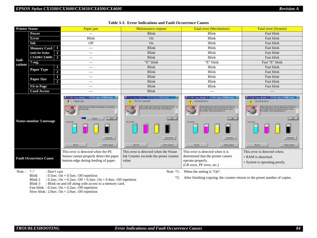
EPSON Stylus CX3500/CX3600/CX3650/CX4500/CX4600 Revision A
T 84
Pr nism) Fatal error (System)
Inca
Fast blinkFast blinkFast blinkFast blinkFast blinkFast blink
Fast “E” blinkFast blinkFast blinkFast blinkFast blinkFast blink
—
St
Fa
n it is r cannot
This error is detected when;• RAM is abnormal.• System is operating poorly.
N
he counter returns to the preset number of copies.
ROUBLESHOOTING Error Indications and Fault Occurrence Causes
inter Status Paper jam Maintenance request Fatal error (Mecha
di-tions
Power — Blink BlinkError Blink On BlinkInk Off On BlinkMemory Card(only for Stylus CX4500/CX4600)
1 — Blink Blink2 — Blink Blink3 — Blink Blink
7-seg. — “E” blink “E” blink
Paper Type1 — Blink Blink2 — Blink Blink
Paper Size1 — Blink Blink2 — Blink Blink
Fit to Page — Blink BlinkCard Access — Blink —
atus monitor 3 message
ult Occurrence Cause
This error is detected when the PE Sensor cannot properly detect the paper bottom edge during feeding of paper.
This error is detected when the Waste Ink Counter exceeds the preset counter value.
This error is detected whedetermined that the printeoperate properly.(CR error, PF error, etc.)
Table 3-3. Error Indications and Fault Occurrence Causes
ote : “–” : Don’t careBlink : 0.5sec. On + 0.5sec. Off repetitionBlink 2 : 0.2sec. On + 0.2sec. Off + 0.2sec. On + 0.4sec. Off repetitionBlink 3 : Blink on and off along with access to a memory card.Fast blink : 0.2sec. On + 0.2sec. Off repetitionSlow blink : 2.0sec. On + 2.0sec. Off repetition
Note *1: When the setting is “On”.
*2: After finishing copying, t

EPSON Stylus CX3500/CX3600/CX3650/CX4500/CX4600 Revision A
T 85
3.Yo t the SPC to your PC and see an error message on the “DISASSEMBLY AND ASSEMBLY”. The fol
enon
Remedy
••
he 1. Connect the Panel FFC to CN1 on the Panel Board.
2. Replace the Panel FFC with new one.3. Replace the Panel Board with new one.
ROUBLESHOOTING Troubleshooting
3 Troubleshootingu can identify the troubles by using the checklist in this section after confirming the LED indication on the SPC. If you connec STM3, you can short the total repair time. And, when you find out the defective parts, replace them by referring the Chapter 4lowing tables describe the error check points.
Table 3-4. Check point for the communication error according to each phenomOccurrence
timingCR position
Detailed phenomenon Defective unit/part name Check point
Power onAnywhere
When turning on the power, the SPC does not operate at all. Panel Unit
1. Check if the Panel FFC is connected to the CN1 on tPanel Board.
2. Check if the Panel FFC is not damaged.3. Check if the Panel Board is not damaged.
CN1Panel Board Panel FFC

EPSON Stylus CX3500/CX3600/CX3650/CX4500/CX4600 Revision A
T 86
••
to 1. Connect the PS Board Connector Cable to CN1 on the Main Board.
not 2. Replace the PS Board Unit with new one.* If the problem is not solved, replace the
Main Board with new one.
••
C 1. Connect the USB Cable to the SPC and the PC.
he 1. Use the Adjustment Program to write the correct value to the EEPROM address.
the 2. Connect the Panel FFC to the CN12 on the Main Board.
enon
Remedy
ROUBLESHOOTING Troubleshooting
Power onAnywhere
When turning on the power, the SPC does not operate at all. PS Board Unit
1. Check if the PS Board Connector Cable is connectedthe CN1 on the Main Board.
2. Check if the PS Board Connector Cable/PS Board is damaged.
Operation–
When turning on the power, the power on sequence is performed correctly. But, when any printer job is sent to the SPC, a communication error is indicated with STM3.
USB Cable 1. Check if the USB Cable is connected between the SPand the PC.
Main Board Unit
1. Check if an incorrect model name is not stored into taddress of the EEPROM on the Main Board.
2. Check if the Panel FFC is connected to the CN12 on Main Board.
Table 3-4. Check point for the communication error according to each phenomOccurrence
timingCR position
Detailed phenomenon Defective unit/part name Check point
CN1
Main Board
PS Board Connector Cable
PS Board Unit
CN12
Main Board Panel FFC

EPSON Stylus CX3500/CX3600/CX3650/CX4500/CX4600 Revision A
T 87
henomenon
Remedy
••
t to 1. Replace the Ink Cartridge with a brand-new one.
ss of 1. Set the proper destination by using Adjustment Program.
••
t to 1. Replace the Ink Cartridge with a brand-new one.
1. Replace the Ink Cartridge with a brand-new one.
t to 2. Replace the Ink Cartridge with a brand-new one.
ROUBLESHOOTING Troubleshooting
Table 3-5. Check point for the error before the initial ink charge according to each pOccurrence
timingCR position
Detailed phenomenon Defective unit/part name Check point
Power onInside HP
The SPC does not perform the initial ink charge and an error is indicated with LEDs and STM3.
Ink Cartridge 1. Check if the Ink Cartridge can be used by installing iother SPC.
Main Board 1. Check if an incorrect data is not stored into the addrethe EEPROM on the Main Board.
Power onAnywhere
The SPC does not perform the ink replacement CL and an error is indicated with LEDs and STM3.
Ink Cartridge1. Check if the Ink Cartridge can be used by installing i
other SPC.
The SPC does not perform the printing operation and an error is indicated with LEDs and STM3.
Ink Cartridge
1. Check if the ink is remaining in the Ink Cartridge.
2. Check if the Ink Cartridge can be used by installing iother SPC.

EPSON Stylus CX3500/CX3600/CX3650/CX4500/CX4600 Revision A
T 88
Remedy
••
d. 1. Properly install the Torsion Spring 19.01.* Only when the Torsion Spring 19.01 comes
off while the PG lever is set to “H” position.
1. Replace the PG Sensor with a new one.
1. Replace the Main Board with a new one.
henomenon
Remedy
••
d 1. Switch to Index Sheet printed from an inserted Memory Card.
ta is 1. Insert Memory Card storing the Index Sheet data.
2. Replace the Memory Card with a new one.
ROUBLESHOOTING Troubleshooting
Table 3-6. Check point for the PG error according to each phenomenonOccurrence
timingCR position
Detailed phenomenon Defective unit/part name Check point
Operation–
This error is generated when using stand-alone copy.
Torsion Spring 19.01
1. Check if the Torsion Spring 19.01 is properly installe
PG Sensor
1. Check if the PG Sensor is not damaged.
Main Board 1. Check if the Main Board is not damaged.
Torsion Spring 19.01
PG Sensor
Table 3-7. Check point for the Index Sheet error (incorrect card) according to each pOccurrence
timingCR position
Detailed phenomenon Defective unit/part name Check point
Operation–
This error is generated when attempting to print from Index Sheet.
Index Sheet 1. Check if the Index Sheet was printed from an inserteMemory Card.
Memory Card1. Check if the Memory Card storing the Index Sheet da
inserted.2. Check if the Memory Card is not damaged.

EPSON Stylus CX3500/CX3600/CX3650/CX4500/CX4600 Revision A
T 89
phenomenon
Remedy
••
red 1. Properly cover over mark.
henomenon
Remedy
••
1. Set the Index Sheet correctly.n. 2. Reprint the Index Sheet.
1. Close the Document Cover.
1. Clean the Document Glass.
ROUBLESHOOTING Troubleshooting
Table 3-8. Check point for the Index Sheet error (incorrect marking) according to eachOccurrence
timingCR position
Detailed phenomenon Defective unit/part name Check point
Operation–
This error is generated when attempting to print from Index Sheet. Index Sheet 1. Check if mark of Index Sheet has been properly cove
over.
Table 3-9. Check point for the Index Sheet error (No index sheet) according to each pOccurrence
timingCR position
Detailed phenomenon Defective unit/part name Check point
Operation–
This error is generated when attempting to print from Index Sheet.
Index Sheet1. Check if the Index Sheet is set in the wrong way.2. Check if the Index Sheet standard position is not clea
Document Cover 1. Check if the Document Cover is not open.
Scanner Housing Upper
1. Check if the Document Glass is not clean.
Document Glass

EPSON Stylus CX3500/CX3600/CX3650/CX4500/CX4600 Revision A
T 90
enon
Remedy
••
1. Replace the Memory Card with an acceptable one.
2. Replace the Memory Card with a new one.rd is 1. Change the Main Board Unit with a new one.
enon
Remedy
••
tly 1. Set the Extension Spring Retard between the Retard Roller Unit and the ASF Frame.
he 2. Set the Torsion Spring 6.45 between the ASF Frame and the Paper Back Lever.
ROUBLESHOOTING Troubleshooting
Table 3-10. Check point for the Memory Card error according to each phenomOccurrence
timingCR position
Detailed phenomenon Defective unit/part name Check point
Operation–
The Memory Card is unrecognized and an error is displayed.
Memory Card1. Check if the Memory Card is acceptable.
2. Check if the Memory Card is not damaged.
Main Board Unit 1. Check if the Memory Card slot pins on the Main Boanot bended.
Table 3-11. Check point for the Double feed error according to each phenomOccurrence
timingCR position
Detailed phenomenon Defective unit/part name Check point
Operation–
After both surfaces were printed, the paper was ejected but an error is displayed.
ASF Unit
1. Check if the Extension Spring Retard operates correcin the paper loading sequence.
2. Check if the Paper Back Lever operates correctly in tpaper loading sequence.
Extension Spring Retard
Paper Back LeverTorsion Spring 6.45

EPSON Stylus CX3500/CX3600/CX3650/CX4500/CX4600 Revision A
T 91
on
Remedy
••
of 1. Set a cleaning sheet in the ASF Unit up side down. Then holding the top edge, try to load the paper from the Printer driver. The micro pearl on the LD Roller surface is removed. To remove severe smear, staple a cloth moistened with alcohol to a post card and clean the roller in the same manner.
*If the problem is not solved, replace the Holder shaft unit with new one.
••
1. Reassemble the Compression Spring 5.58 between the ASF Frame and the Hopper.
Non-adhesive Area(Use a post card for the base sheet)
Staplers
Cloth moistened with alcohol
CL Sheet
Adhesive Area
This side down
ROUBLESHOOTING Troubleshooting
Table 3-12. Check point for the paper out error according to each phenomenOccurrence
timingCR position
Detailed phenomenon Defective unit/part name Check point
Operation–
The LD Roller cannot pick up paper although the LD Roller attempt to rotate correctly.
Holder Shaft Unit
1. Check if any paper dust is not adhered to the surface the LD Roller.
Operation–
The Hopper does not operate during the paper loading sequence although the LD Roller rotates to load paper from the ASF Unit.
ASF Unit
1. Check if the Hopper operates correctly in the paper loading sequence.
LD Roller
Compression Spring5.58
Hopper

EPSON Stylus CX3500/CX3600/CX3650/CX4500/CX4600 Revision A
T 92
••
ff in 1. Reassemble the Extension Spring 0.143 in the Clutch mechanism.
l of 2. Reassemble the round portion of the Clutch on the dowel of the LD Roller Shaft.
3. Replace the Holder Shaft Unit with a new one.
4. Replace the Holder Shaft Unit with a new one.
on
Remedy
ROUBLESHOOTING Troubleshooting
Operation–
The drive of the PF Motor is not transmitted to the LD Roller Shaft. Holder Shaft Unit
1. Check if the Extension Spring 0.143 does not come othe Clutch mechanism.
2. Check if the Clutch does not come off from the dowethe LD Roller Shaft.
3. Check if the Clutch tooth is not damaged.
4. Check if the Clutch is not damaged.
Table 3-12. Check point for the paper out error according to each phenomenOccurrence
timingCR position
Detailed phenomenon Defective unit/part name Check point
Extension Spring 0.143
Clutch tooth
Dowel

EPSON Stylus CX3500/CX3600/CX3650/CX4500/CX4600 Revision A
T 93
••
off 1. Replace the Ink System Unit with a new one.
••
1. Replace the Ink System Unit with a new one.
on
Remedy
ROUBLESHOOTING Troubleshooting
Operation–
The drive of the PF Motor is not transmitted to the LD Roller Shaft. Ink System Unit
1. Check if the Compression Spring 2.36 does not comein the Change Lever.
Operation–
The LD Roller is not set to the ASF home position and paper is always loaded from the ASF Unit during the paper loading sequence.
Ink System Unit
1. Check if the tip of the Change Lever is not damaged.
Table 3-12. Check point for the paper out error according to each phenomenOccurrence
timingCR position
Detailed phenomenon Defective unit/part name Check point
Compression Spring 2.36
Change Lever

EPSON Stylus CX3500/CX3600/CX3650/CX4500/CX4600 Revision A
T 94
to each phenomenon
Remedy
••
1. Install the Ink Cartridge properly. 2. Replace the Ink Cartridge with a new one.
the 1. Connect the Head FFC to connector on the CSIC Board.
2. Replace the Carriage Unit with a new one.1. Replace the Carriage Unit with a new one.
ROUBLESHOOTING Troubleshooting
Table 3-13. Check point for the No ink cartridge/CSIC error/Incorrect ink cartridge accordingOccurrence
timingCR position
Detailed phenomenon Defective unit/part name Check point
Power onInside HP
After the Carriage has detected the HP, an error is displayed.
Ink Cartridge
1. Check if Ink Cartridge is properly installed.2. Check if the Memory Chip is not disconnected or not
chipped.
CSIC Board
1. Check if the Head FFC is connected to connector on CSIC Board.
2. Check if the CSIC Board is not damaged.
CSIC Connector
3. Check if the CSIC Connector is not damaged.
Memory Chip
Connector
Head FFC
CSIC Connectors
CSIC Board

EPSON Stylus CX3500/CX3600/CX3650/CX4500/CX4600 Revision A
T 95
non
Remedy
••
1. Install the ASF Unit properly.he 2. Set the Torsion Spring 6.45 between the ASF
Frame and the Paper Back Lever.
. 1. Set the Torsion Spring 0.22 between the Holder Shaft and the PE Sensor Lever.
ROUBLESHOOTING Troubleshooting
Table 3-14. Check point for the paper jam error according to each phenomeOccurrence
timingCR position
Detailed phenomenon Defective unit/part name Check point
OperationOutside HP
The paper feeding sequence is performed without loading paper in the paper loading sequence.
ASF Unit
1. Check if the ASF Unit is properly installed.2. Check if the Paper Back Lever operates correctly in t
paper loading sequence.
Holder Shaft Unit
1. Check if the Torsion Spring 0.22 is properly installed
Paper Back LeverTorsion Spring 6.45
TorsionSpring 0.22
PE Sensor Lever
PE Sensor

EPSON Stylus CX3500/CX3600/CX3650/CX4500/CX4600 Revision A
T 96
••
tly 1. Set the Extension Spring Retard between the Retard Roller Unit and the ASF Frame.
. 1. Set the Torsion Spring 0.22 between the Holder Shaft and the PE Sensor Lever.
••
1. Reassemble the EJ Frame Unit correctly.
2. Reassemble the EJ Roller Unit correctly.
* al condition in the next operation. Therefore, the paper
** may be damaged.
non
Remedy
ROUBLESHOOTING Troubleshooting
OperationOutside HP
Paper is being resent during paper feeding operation. ASF Unit
1. Check if the Extension Spring Retard operates correcin the paper loading sequence.
When turning on the power, the Carriage Unit move to the home position correctly. But, the paper feeding sequence is performed without loading paper in the paper loading sequence.
Holder Shaft Unit*
1. Check if the Torsion Spring 0.22 is properly installed
Operation–
The leading edge of paper does not go through between the EJ Roller Unit and the Star Wheel.
EJ Frame Unit**
1. Check if the EJ Frame Unit is correctly assembled.
2. Check if the EJ Roller Unit is correctly assembled.
The Carriage Unit can move to home position even if the Torsion Spring 0.22 comes off. However, the PE Sensor Lever keeps the high signjam error is detected.In case that the paper jam error occurs in each operation, the jammed paper contacts the nozzle surface of the Print Head and the Print Head
Table 3-14. Check point for the paper jam error according to each phenomeOccurrence
timingCR position
Detailed phenomenon Defective unit/part name Check point
Extension Spring Retard
EJ Frame Unit
EJ Roller UnitSpur Gear 36

EPSON Stylus CX3500/CX3600/CX3650/CX4500/CX4600 Revision A
T 97
••
3. Reassemble the Star Wheel Holders correctly.
4. Replace the EJ Frame Unit with a new one.1. Reassemble the Paper Guide Upper Unit to
the Main Frame correctly.
* al condition in the next operation. Therefore, the paper
** may be damaged.
non
Remedy
ROUBLESHOOTING Troubleshooting
Operation–
The leading edge of paper does not go through between the EJ Roller Unit and the Star Wheel.
EJ Frame Unit**
3. Check if the Star Wheel Holders does not come off.
4. Check if the Spur Gear 36 is not damaged.
The leading edge of paper is not loaded to the PF Roller Unit.
Paper Guide Upper Unit **
1. Check if the Paper Guide Upper Unit is correctly assembled.
The Carriage Unit can move to home position even if the Torsion Spring 0.22 comes off. However, the PE Sensor Lever keeps the high signjam error is detected.In case that the paper jam error occurs in each operation, the jammed paper contacts the nozzle surface of the Print Head and the Print Head
Table 3-14. Check point for the paper jam error according to each phenomeOccurrence
timingCR position
Detailed phenomenon Defective unit/part name Check point
Star Wheel Holders
Paper Guide Upper Unit

EPSON Stylus CX3500/CX3600/CX3650/CX4500/CX4600 Revision A
T 98
n
Remedy
••
1. Connect the Scanner Motor Connector Cable to CN10 on the Main Board.
bout 2. Replace the Scanner Motor with a new one.
3. Replace the Scanner Motor with a new one.
ROUBLESHOOTING Troubleshooting
Table 3-15. Check point for the Fatal error according to each phenomenoOccurrence
timingCR position
Detailed phenomenon Defective unit/part name Check point
Power onAnywhere
The Scanner Unit does not initialize when the power is turned on. Scanner Motor
1. Check if the Scanner Motor Connector Cable is connected to CN10 on the Main Board.
2. Check if the coil resistance of the Scanner Motor is a37Ω by using the tester (refer to Table 3-1).
3. Check if the Scanner Motor Connector Cable is not damaged.
Scanner MotorConnector Cable
CN10
Scanner Motor

EPSON Stylus CX3500/CX3600/CX3650/CX4500/CX4600 Revision A
T 99
••
1. Connect the Scanner HP Sensor Connector Cable to CN13 on the Main Board.
ot 2. Replace the Scanner HP Sensor with a new one.
3. Replace the Scanner HP Sensor with a new one.
N11 1. Connect the Scanner Carriage FFC to CN11 on the Main Board.
2. Replace the Scanner Carriage FFC with a new one.
n
Remedy
ROUBLESHOOTING Troubleshooting
Power onAnywhere
The Scanner Unit does not initialize when the power is turned on.
Scanner HP Sensor
1. Check if the Scanner HP Sensor Connector Cable is connected to CN13 on the Main Board.
2. Check if the Scanner HP Sensor Connector Cable is ndamaged.
3. Check if the Scanner HP Sensor is not damaged.
Scanner Carriage FFC
1. Check if the Scanner Carriage FFC is connected to Con the Main Board.
2. Check if the Scanner Carriage FFC is not damaged.
Table 3-15. Check point for the Fatal error according to each phenomenoOccurrence
timingCR position
Detailed phenomenon Defective unit/part name Check point
Scanner HP SensorConnector Cable
CN13
Scanner HP Sensor
Scanner Carriage FFC CN11

EPSON Stylus CX3500/CX3600/CX3650/CX4500/CX4600 Revision A
T 100
••
1. Replace the Scanner Carriage Unit with a new one.
••
to 1. Connect the CR Motor Connector Cable to CN8 on the Main Board.
ged. 2. Replace the CR Motor with a new one.
3. Replace the CR Motor with a new one.
to 1. Connect the PF Motor Connector Cable to CN9 on the Main Board.
ed. 2. Replace the PF Motor with a new one.
3. Replace the PF Motor with a new one.
n
Remedy
ROUBLESHOOTING Troubleshooting
Power onAnywhere
The Scanner Unit does not initialize when the power is turned on.
Scanner Carriage Unit
1. Check if the Scanner Carriage Unit is not damaged.
Power onAnywhere
When turning on the power, the CR Motor does not operate at all. CR Motor
1. Check if the CR Motor Connector Cable is connectedCN8 on the Main Board.
2. Check if the CR Motor Connector Cable is not dama
3. Check if the CR Motor operates.
When turning on the power, the PF Motor does not operate at all. PF Motor
1. Check if the PF Motor Connector Cable is connectedCN9 on the Main Board.
2. Check if the PF Motor Connector Cable is not damag
3. Check if the PF Motor operates.
Table 3-15. Check point for the Fatal error according to each phenomenoOccurrence
timingCR position
Detailed phenomenon Defective unit/part name Check point
Scanner Carriage Unit
CN8
CR MotorConnector Cable
CR Motor
PF MotorConnector Cable
CN9
PF Motor

EPSON Stylus CX3500/CX3600/CX3650/CX4500/CX4600 Revision A
T 101
••
to 1. Connect the PF Motor Connector Cable to CN9 on the Main Board.
ed. 2. Replace the PF Motor with a new one.
3. Replace the PF Motor with a new one.
off 1. Replace the Ink System Unit with a new one.
••
1. Reassemble the Paper Guide Upper Unit to the Main Frame correctly.
n
Remedy
ROUBLESHOOTING Troubleshooting
Power onAnywhere
When turning on the power, the Carriage Unit collides to the Change Lever located to the front side of the printer.
PF Motor
1. Check if the PF Motor Connector Cable is connectedCN9 on the Main Board.
2. Check if the PF Motor Connector Cable is not damag
3. Check if the PF Motor operates.
Ink System Unit
1. Check if the Compression Spring 2.36 does not comein the Change Lever.
Power onAnywhere
The Carriage Unit collides with the Guide Upper Unit when power is turned on.
Paper GuideUpper Unit
1. Check if the Paper Guide Upper Unit is correctly assembled.
Table 3-15. Check point for the Fatal error according to each phenomenoOccurrence
timingCR position
Detailed phenomenon Defective unit/part name Check point
Compression Spring 2.36
Change Lever
Paper Guide Upper Unit

EPSON Stylus CX3500/CX3600/CX3650/CX4500/CX4600 Revision A
T 102
••
ly 1. Reassemble the CR Scale correctly.* If the problem is not solved, replace the
Main Board with a new one.
d. 2. Replace the CR Scale with a new one or clean it completely.
1. Connect the Encoder FFC to the CR Encoder Board.
2. Replace the Encoder FFC with a new one.
3. Replace the CR Encoder Board with a new one.
n
Remedy
ROUBLESHOOTING Troubleshooting
Power onAnywhere
When turning on the power, the Carriage Unit collides to the right side of the Main Frame.
CR Scale
1. Check if the CR Scale does not come off or it properpasses through the slit of the CR Encoder Board.
2. Check if the CR Scale is not damaged or contaminate
CR Encoder Board
1. Check if the Encoder FFC is connected to the CR Encoder Board.
2. Check if the Encoder FFC is not damaged.
3. Check if the CR Encoder Board is not damaged.
Table 3-15. Check point for the Fatal error according to each phenomenoOccurrence
timingCR position
Detailed phenomenon Defective unit/part name Check point
Slit of the CR Encoder Board
CR Scale
Encoder FFCCR Encoder Board

EPSON Stylus CX3500/CX3600/CX3650/CX4500/CX4600 Revision A
T 103
••
d. 1. Replace the PF Scale with a new one.
2. Replace the Main Board Unit with a new one.
••
1. After wiping the grease on the Scanner Carriage Shaft with a dry, soft cloth, coat it with grease (G-26 Grease). (Refer to Chapter 6 “MAINTENANCE”.)
2. Reassemble the Scanner Carriage Shaft to the Scanner Carriage Unit.
••
to 1. Connect the PE Sensor Connector Cable to CN3 on the Main Board.
ged. 2. Replace the PE Sensor with a new one.
3. Replace the PE Sensor with a new one.
n
Remedy
ROUBLESHOOTING Troubleshooting
Power onAnywhere
The eject rollers are rotating at high speed when power is turned on. (For about 1 cycle.)
PF Scale / Main Board Unit
1. Check if the PF Scale is not damaged or contaminate
2. Check if the PF Encoder Sensor is not damaged.
OperationAnywhere
The Scanner Carriage Unit does not operate.
Scanner Carriage Shaft
1. Check if the grease is enough on the surface of the Scanner Carriage Shaft.
2. Check if the Scanner Carriage Shaft is set correctly.
OperationAnywhere
The paper feeding sequence is performed without loading a paper in the paper loading sequence.
Holder Shaft Unit
1. Check if the PE Sensor Connector Cable is connectedCN3 on the Main Board.
2. Check if the PE Sensor Connector Cable is not dama
3. Check if the PE Sensor is not damaged.
Table 3-15. Check point for the Fatal error according to each phenomenoOccurrence
timingCR position
Detailed phenomenon Defective unit/part name Check point
PF Scale
PF Encoder Sensor
PE Sensor Connector CableCN3

EPSON Stylus CX3500/CX3600/CX3650/CX4500/CX4600 Revision A
T 104
••
y 1. Replace the Front Frame with a new one.
y 1. Replace the Printer Mechanism with a new one.
n
Remedy
ROUBLESHOOTING Troubleshooting
OperationAnywhere
The Carriage Unit climbs over the Slider Lock Lever set to the wiping position and the Carriage Unit collides to its lever.
Front Frame
1. Check if the Slider Lock Lever is correctly released bthe CR movement.
Main Frame 1. Check if the Slider Lock Lever is correctly released bthe CR movement.
Table 3-15. Check point for the Fatal error according to each phenomenoOccurrence
timingCR position
Detailed phenomenon Defective unit/part name Check point
Slider Lock Lever

EPSON Stylus CX3500/CX3600/CX3650/CX4500/CX4600 Revision A
T 105
3.Th STM3) in the previous section.
s and STM3
Remedy
••
tly 1. Set the Extension Spring Retard between the Retard Roller Unit and the ASF Frame.
he 2. Set the Torsion Spring 6.45 between the ASF Frame and the Paper Back Lever.
ROUBLESHOOTING Troubleshooting
3.1 Superficial Phenomenon-Based Troubleshootingis section explains the fault locations of the error states (print quality and abnormal noise) other than the error states (LED and
Table 3-16. Check point for multiple sheets of paper are always loaded without LEDOccurrence
timingCR position
Detailed phenomenon Defective unit/part name Check point
Operation–
The LEDs and STM3 are not indicating error conditions. But, multiple sheets of paper are always loaded from the ASF Unit.
ASF Unit
1. Check if the Extension Spring Retard operates correcin the paper loading sequence.
2. Check if the Paper Back Lever operates correctly in tpaper loading sequence.
Extension Spring Retard
Paper Back LeverTorsion Spring 6.45

EPSON Stylus CX3500/CX3600/CX3650/CX4500/CX4600 Revision A
T 106
Remedy
••
1. Wipe off the remaining grease on the Carriage Guide Shaft and lubricate it on its shaft.
1. Wipe off the remaining grease on the Front Frame and lubricate it on its frame.
1. Replace the Ink System Unit with a new one.
1. Replace the EJ Frame Unit with a new one.
rely. 1. Reassemble the Paper Guide Upper to the Main Frame.
Remedy
•
. 1. Remove the extraneous matter from the Document Glass.(Refer to the Chapter 6 “MAINTENANCE”.)
1. Remove the extraneous matter from the Document Glass (blow away the dusts).
1. Replace the Scanner Carriage Unit with new one.
ROUBLESHOOTING Troubleshooting
Table 3-17. Check point for the abnormal noiseOccurrence
timingCR position
Detailed phenomenon Defective unit/part name Check point
AnywhenAnywhere
The abnormal noise occurs at the first power on timing and during each operation although the printing operation is performed.
Carriage Unit1. Check if the grease on the Carriage Guide Shaft is
sufficient.
Front Frame 1. Check if the grease on the Front Frame is sufficient.
Ink System Unit 1. Check if the Change Lever moves smoothly.
The bottom of the Carriage Unit contacts the surface of the EJ Frame Unit. EJ Frame Unit 1. Check if the EJ Frame Unit is not bent up.
The Carriage Unit collides to the Paper Guide Upper Unit during each operation.
Paper Guide Upper Unit
1. Check if the Paper Guide Upper Unit is attached secu(check if it interferes with the Carriage Unit)
Table 3-18. Check point for poor scanned image qualityScanned image Quality State Detailed phenomenon Defective
unit/part name Check point
Scanned image is not clear.
There are dusts on the Document Glass. (white dots appear on the scanned image)
Scanner Housing Upper
1. Check if there is not any dust on the Document Glass
There are dusts on the LED in the Rod Lens Array. (vertical stripes appear on the scanned image)
Scanner Carriage Unit
1. Check if there is not any dust on the LED.
The LED of Scanner Carriage Unit does not light up.
Scanner Carriage Unit
1. Check if the LED lights up.

EPSON Stylus CX3500/CX3600/CX3650/CX4500/CX4600 Revision A
T 107
Remedy
•
und 1. Remove the foreign material around the seal rubber parts carefully.
2. Replace the Ink System Unit with a new one.
tion 1. Perform CL operation and the Ink Cartridge replacement specified times. If it doesn’t work, change the Print Head with a new one.
2. Replace the Print Head with a new one.or 1. Replace Ink System Unit with a new one.
1. Replace the Main Board with a new one.
ROUBLESHOOTING Troubleshooting
Table 3-19. Check point for the poor printing qualityPrint Quality
State Detailed phenomenon Defective unit/part name Check point
Dot missing and mixed colors
Ink is scarcely ejected to the Cap from the Print Head.
Ink System Unit (Cap Unit)
1. Check if there is not any foreign material/damage arothe seal rubber part on the Cap Unit.
2. Check if the Compression Spring 1.47 is correctly mounted on the Cap Unit.
Ink is ejected to the Cap from the Print Head, but the SPC does not recover from the error after cleaning or ink change.
Print Head
1. Check if it returns to normal by performing CL operaor replacing the Ink Cartridge.
2. Check if the Print Head is not damaged.
Cleaner Blade 1. Check if the Cleaner Blade does not have paper dust bending.
Main Board 1. Check if the Main Board is not damaged.
Seal rubber part
CompressionSpring 1.47

EPSON Stylus CX3500/CX3600/CX3650/CX4500/CX4600 Revision A
T 108
•
rint N5,
1. Connect the Head FFC to the Print Head and the Main Board Connectors.
2. Replace the Head FFC with a new one.tion 1. Perform CL operation and the Ink Cartridge
replacement specified times. If it doesn’t work, change the Print Head with a new one.
1. Replace the Main Board Unit with a new one.
Remedy
ROUBLESHOOTING Troubleshooting
White streak / abnormal discharge
Ink is ejected to the Cap from the Print Head, but printing is not done at all after cleaning or ink change, or abnormal discharge occurs.
Head FFC
1. Check if the Head FFC is securely connected to the PHead Connectors and the Main Board Connectors (CCN6, CN7).
2. Check if the Head FFC is not damaged.
Print Head
1. Check if it returns to normal by performing CL operaor replacing the Ink Cartridge.
Main Board Unit 1. Check if the Main Board is not damaged.
Table 3-19. Check point for the poor printing qualityPrint Quality
State Detailed phenomenon Defective unit/part name Check point
Print Head
Connectors
CN6
HeadFFC
CN7
CN5

EPSON Stylus CX3500/CX3600/CX3650/CX4500/CX4600 Revision A
T 109
•
ent 1. Perform Bi-D Adjustment to eliminate displacements between the upper and lower rules. (Refer to Chapter 5 “ADJUSTMENT”.)
zle 1. Perform Head Cleaning and check the Nozzle Check Pattern. (Refer to Chapter 5 “ADJUSTMENT”.) If the problem is not solved, replace the Print Head with a new one.
ce 1. Remove foreign objects from surface of the Carriage Guide Shaft.
to nd
2. Reassemble the Carriage Guide Shaft correctly.
3. After wiping the grease on the Carriage Guide Shaft and the Carriage with a dry, soft cloth, coat it with grease (KEN Grease). (Refer to Chapter 6 “MAINTENANCE”.)
f the 4. Replace the Carriage Guide Shaft with a new one.
ce 1. Remove foreign matter from the Front Frame.
2. After wiping the grease on the Front Frame with a dry, soft cloth, coat it with grease (KEN Grease). (Refer to Chapter 6 “MAINTENANCE”.)
3. Replace the Front Frame with a new one.
Remedy
ROUBLESHOOTING Troubleshooting
White streak/color unevenness occurrence
Vertical banding appears against the CR movement direction. And, it looks like uneven printing.
[Note]If the problem is not solved, replace the CR Motor with a new one.
Adjustment1. For printing in the Bi-D mode, check if Bi-D Adjustm
has been performed properly.
Print Head
1. Check if each segment is printed correctly in the NozCheck Pattern.
Carriage Unit / Carriage Guide
Shaft
1. Check if there is not any foreign material on the surfaof the Carriage Guide Shaft.
2. Check if the Carriage Guide Shaft is properly securedMain Frame by the CR Guide Shaft Torsion Spring athe CR Guide Shaft Pressing Spring.
3. Check if the grease is enough on the surface of the Carriage Guide Shaft.
4. Check if any damage is not observed on the surface oCarriage Guide Shaft.
Front Frame
1. Check if there is not any foreign material on the surfaof the Front Frame.
2. Check if the Front Frame is lubricated with enough grease.
3. Check if the Front Frame has not been deformed.
Table 3-19. Check point for the poor printing qualityPrint Quality
State Detailed phenomenon Defective unit/part name Check point
CR movement direction
CR Guide ShaftTorsion Spring
CR Guide ShaftPressing Spring

EPSON Stylus CX3500/CX3600/CX3650/CX4500/CX4600 Revision A
T 110
•
inter 1. Use the suitable paper according to the printer driver setting.
zle 1. Perform the Head Cleaning and check the Nozzle Check Pattern. (Refer to Chapter 5 “ADJUSTMENT”.) If the problem is not solved, replace the Print Head with a new one.
ce 1. Clean the surface of the PF Roller Unit carefully with the soft cloth.
2. Replace the PF Roller Unit with a new one.1. Reassemble the Star Wheel Holder correctly.2. Replace the EJ Frame Unit with a new one.
inter 1. Use the suitable paper according to the printer driver setting.
OM 1. Input 13 digits code of the Head ID into the EEPROM by using the Adjustment Program.
Remedy
ROUBLESHOOTING Troubleshooting
White streak/color unevenness occurrence
Micro banding appears horizontally against the CR movement direction and it appears with the same width.
[Note]If the problem is not solved, replace the PF Motor with a new one.
Printer driver & exclusive paper
1. Check if the suitable paper is used according to the prdriver setting.
Print Head
1. Check if each segment is printed correctly in the NozCheck Pattern.
PF Roller Unit
1. Check if there is not any foreign material on the surfaof the PF Roller Unit.
2. Check if the PF Roller Unit is not damaged.The Star wheel mark against the CR movement direction.
EJ Frame Unit
1. Check if the Star Wheel Holder does not come off.2. Check if the surface of the EJ Frame Unit is flat.
Printing is blurred.
Printer driver & exclusive paper
1. Check if the suitable paper is used according to the prdriver setting.
Print Head 1. Check if the correct Head ID is stored into the EEPRby using the Adjustment Program.
Table 3-19. Check point for the poor printing qualityPrint Quality
State Detailed phenomenon Defective unit/part name Check point
CR movement direction
PF Roller Unit

EPSON Stylus CX3500/CX3600/CX3650/CX4500/CX4600 Revision A
T 111
•
of 1. Set a cleaning sheet in the ASF up side down. Then holding the top edge, try to load the paper from the Printer driver. The micro pearl on the LD Roller surface is removed. To remove severe smear, staple a cloth moistened with alcohol to a post card and clean the roller in the same manner. As for the cleaning sheet, refer to page 91 “Remedy of the Paper out error” * If the problem is not solved, replace the
Holder Shaft Unit with a new one.
•
ink 1. Clean the Paper Guide Front Unit with a soft cloth.
aper 2. Replace the Paper Guide Front Unit with a new one.
in. 1. Clean the EJ Roller Unit with a soft cloth.
in. 1. Clean the PF Roller Unit with a soft cloth.
Remedy
ROUBLESHOOTING Troubleshooting
Print start position slip
The printing operation is correctly performed. But, the top margin is insufficient than usual one.
Holder Shaft Unit
1. Check if any paper dust is not adhered to the surface the LD Roller.
Ink stain of paper Ink stain occurs at the back, top end or bottom end of the print paper.
Paper Guide Front Unit
1. Check if the Paper Guide Front Unit does not have thestain.
2. Check if heaps of ink are not formed on Porous Pad PGuide Front.
EJ Frame Unit 1. Check if the EJ Roller Unit does not have the ink sta
PF Roller Unit 1. Check if the PF Roller Unit does not have the ink sta
Table 3-19. Check point for the poor printing qualityPrint Quality
State Detailed phenomenon Defective unit/part name Check point
LD Roller
Paper Guide Front Unit
Porous Pad Paper Guide Front

EPSON Stylus CX3500/CX3600/CX3650/CX4500/CX4600 Revision A
T 112
•
rop. 1. Clean the Print Head Cover carefully with a soft cloth.
he 1. Clean the Paper Guide Upper Unit with a soft cloth.
1. Clean the Star Wheel Rollers with a soft cloth.
Remedy
ROUBLESHOOTING Troubleshooting
Ink stain of paper Ink sticks to other than the print area of the paper, resulting in contamination
Print Head 1. Check if the Print Head Cover does not have the ink d
Paper Guide Upper Unit
1. Check if the Paper Guide Upper Unit does not have tink stain.
EJ Frame Unit
1. Check if the Star Wheel Rollers does not have the inkstain.
Table 3-19. Check point for the poor printing qualityPrint Quality
State Detailed phenomenon Defective unit/part name Check point
Star Wheel Holder(Front)
Star Wheel RollersStar Wheel Holder
(Rear)
Star Wheel Roller

C H A P T E R
DISA BLY AND ASSEMBLY
SSEM
EPSON Stylus CX3500/CX3600/CX3650/CX4500/CX4600 Revision A
D 114
4.ThCXuniThundaredesIf tdisAn“Anot
Re
4.SeefolCX
ncer, assure vous que l’imprimante soit eteinte d’alimentation soit debranche.s piles usagees selon le reglement local.
i la pile est remplacée incorrectment. Ne ne pile du même type ou d’un type équivalent abricant. Eliminer les piles déchargées selon les curité en vigueur.
ing the printer after installing the ink cartridge, he printer for transportation without removing .ended tools for disassembling, assembling or
inter.ified torque when tightening screws. and adhesives as specified. (Refer to Chapter 6
ed adjustments when you disassemble the
r 5 for details.)p of the waste ink tube is located at correct assembling the waste ink tube. Otherwise it will e.
ISASSEMBLY AND ASSEMBLY Overview
1 Overviewis section describes procedures for disassembling the main components of the Stylus 3500/CX3600/CX3650/CX4500/CX4600. Unless otherwise specified, disassembly ts or components can be reassembled by reversing the disassembly procedure. ings, if not strictly observed, that could result in injury or loss of life are described er the heading “Warning”. Precautions for any disassembly or assembly procedures
described under the heading “CAUTION”. Chips for disassembling procedures are cribed under the heading “CHECK POINT”. he assembling procedure is different from the reversed procedure of the assembling, the procedure is described under the heading “REASSEMBLY”.y adjustments required after reassembling the units are described under the heading DJUSTMENT REQUIRED”. When you have to remove any units or parts that are described in this chapter, refer to the exploded diagrams in the appendix.
ad precautions described in the next section before starting.
1.1 Precautions the precautions given under the handling “WARNING” and “CAUTION” in the
lowing column when disassembling or assembling EPSON Stylus CX3500/3600/CX3650/CX4500/CX4600.
Disconnect the power cable before disassembling or assembling
the printer. If you need to work on the printer with power applied, strictly
follow the instructions in this manual. Wear protective goggles to protect your eyes from ink. If ink
gets in your eye, flush the eye with fresh water and see a doctor immediately.
Always wear gloves for disassembly and reassembly to avoid iujury from sharp metal edges.
To protect sensitive microprocessors and circuitry, use static discharge equipment, such as anti-static wrist straps, when accessing internal components.
Never touch the ink or wasted ink with bare hands. If ink comes into contact with your skin, wash it off with soap and water immediately. If irritation occurs, contact a physician.
Avant de comme
et que le cordon Veillez a jeter le
Risque d’explosion sremplacer que par urecommandé par le flois et les règles de sé
When transport
be sure to pack tthe ink cartridge
Use only recommadjusting the pr
Observe the spec Apply lubricants
for details.) Make the specifi
printer. (Refer to Chapte
Make sure the tiposition when recause ink leakag

EPSON Stylus CX3500/CX3600/CX3650/CX4500/CX4600 Revision A
D 115
4.Us
No
Ph
Ph
St
PR
Tw
N
A
ISASSEMBLY AND ASSEMBLY Overview
1.2 Toolse only specified tools to avoid damaging of the printer.
te "*": Available in the market
Table 4-1. Tools
Name Supplier* Parts No.
illips Screw Driver (No.1) EPSON 1080530
illips Screw Driver (No.2) EPSON 1080532
andard Screwdriver EPSON 1080527
ECISION SCREW DRIVER #1 (-) EPSON 1080525
eezer EPSON 1080561
eedle nose pliers EPSON 1080564
cetate Tape EPSON 1003963

EPSON Stylus CX3500/CX3600/CX3650/CX4500/CX4600 Revision A
D 116
4.If awo
C
Pr
Sc
Operation is normal? OK / NG
Local copy is normal? OK / NG
Adjustment condition is suitable? OK / NG
Lubrication is done at designated place? OK / NG
Lubrication volume is suitable? OK / NG
The newest version OK / NG
Ink cartridge is normally installed? OK / NG
Remained life of waste ink pads are sufficient? OK / NG
Printer CR is in the cap position? OK / NG
All of attached goods from users are packed? OK / NG
le 4-2. Check ListCheck item Check column
ISASSEMBLY AND ASSEMBLY Overview
1.3 Work Completion Checkny service is made to the printer, use the checklist shown below to confirm all rks are completed properly and the printer is ready to be returned to the user.
Table 4-2. Check Listlassification Part Check item Check column
inter unit Self test Operation is normal? OK / NG
On line test Print is normally done? OK / NG
Print Head (nozzlecheck pattern print)
Ink gets out normally from all the nozzles? OK / NG
CR mechanism CR smoothly operates? OK / NG
CR makes abnormal sound during its operation? OK / NG
Paper loading mechanism
Paper is smoothly loaded? OK / NG
Paper jam does not happen? OK / NG
Paper does not warp during paper loading? OK / NG
Multiple papers are not fed? OK / NG
Abnormal sound is not heard during paper loading? OK / NG
There is no alien substance at paper route? OK / NG
anner unit Mechanism Glass surface is not dirty? OK / NG
Alien substance is not mixed in the CR movement area? OK / NG
CR mechanism CR smoothly operates? OK / NG
CR operates together with scanner unit? OK / NG
CR makes abnormal sound during its operation? OK / NG
LED LED normally turns on and white reflection test is done near home position?
OK / NG
On line test On line test
Copy Copy
Adjustment Designated adjustment items
Lubrication Designated lubrication items
Function Firmware version
Dispatch packing
Ink cartridge
Waste Ink Pads
Protection during distribution
Others Attached goods
TabClassification Part

EPSON Stylus CX3500/CX3600/CX3650/CX4500/CX4600 Revision A
D sure of quality on re-assembled product 117
4.
OnPridefMeFotheMeOnrepThMepro[Ca1)
Lower with positioning hole of Main Frame and
nit/Main Board Unit/Paper Guide Upper Unit
t main frame deformation is caused extra force in , printing failure/operation failure occurs.
hand while you are installing the above parts.
t printing failure occurs by CR Guide Frame
ssembling/disassembling carefully.
ed in assembling/disassembling of your repair, vital problem occur in user’s further operation.
assembling/disassembling carefully.
mbled product]mbled product is ensured if there is no problem program.
ISASSEMBLY AND ASSEMBLY Caution regarding assembling/disassembling of the Printer Mechanism, and how to en
2 Caution regarding assembling/disassembling of the Printer Mechanism, and how to ensure of quality on re-assembled product
current low end models, we basically forbade to remove Housing Lower from nter Mechanism in your repair. This is because there is a possibility of Main Frame ormation when a part (such as Ink System Unit) is removed from Printer chanism without Housing Lower.
r this reason, we recommend that a new Printer Mechanism be replaced along with Housing Lower when a part cannot be replaced without removing the Printer chanism. these models, you have to remove Housing Lower from Printer Mechanism when lacing [Waste Ink Pads] with new one. erefore, we clarify caution regarding assembling/disassembling of the Printer chanism without Housing Lower, and how to ensure of quality on repaired duction this section.ution regarding assembling/disassembling of the Printer Mechanism]
Main Frame(a) Control of assembled standard position.
[Reason]• The assembled accuracy of each part composed of Printer Mechanism is
based on Housing Lower.[Service treatment]• Confirm that there is no gap between Main Frame and Housing Lower.[Reference]• To ensure the assembled accuracy, you have to control the assembled
standard position of main frame against X/Y/Z-axis direction.[X-axis direction]• Make sure that main frame is correctly placed on the groove of Housing
Lower. • Make sure that there is no gap between Main Frame and Housing Lower.[Y-axis direction]• Make sure that main frame is correctly placed on the groove of Housing
Lower. • Make sure that there is no gap between Main Frame and Housing Lower.
[Z-axis direction]• Align dowel of Housing
ensure there is no gap.(b) How to assemble of ASF U
[Reason]• There is a possibility tha
assembling. As the result[Service treatment]• Hold the opposite side by
2) CR Guide Frame(a) Control of vertical level
[Reason]• There is a possibility tha
deformation.[Service treatment]• Handle Front Frame in a
3) Carriage Unit (a) Handling of Carriage Unit
[Reason]• If Carriage Unit is damag
there is a possibility that [Service treatment]• Handle Carriage Unit in
[How to ensure of quality on re-asseWe judge that the quality of re-asseabout the print result by adjustment

EPSON Stylus CX3500/CX3600/CX3650/CX4500/CX4600 Revision A
D 118
4.Th in the figure.
2 ASF Unit” (p.141)
older Shaft Unit” (p.143)
nk System Unit” (p.156)
e “Ink System Unit”, all parts shown es need to be removed.e “Paper Guide Front Unit”, all parts red boxes need to be removed.
ISASSEMBLY AND ASSEMBLY Disassembly
3 Disassemblye flowchart below shows step-by-step disassembly procedures. When disassembling each unit, refer to the page number shown
Figure 4-1. Disassembling flowchart
START
“4.3.1 Document Cover” (p.119)
“4.3.4 Scanner Unit” (p.121)
“4.3.5 Panel Unit” (p.126)
“4.3.6 Housing Upper” (p.127)
“4.3.8 Printer Mechanism” (p.130)
“4.3.11 Main Board Unit” (p.136)
“4.3.17 Carriage Unit” (p.149)
“4.3.20 EJ Frame Unit” (p.154)
“4.3.22 Paper Guide Front Unit” (p.157)
“4.3.23 PG Sensor” (p.158)
“4.3.24 PF Roller Unit” (p.159)
“4.3.19 Front Frame” (p.153)
“4.3.14 CR Guide Frame” (p.146)
“4.3.1
“4.3.13 H
“4.3.9 PS Board Unit” (p.133) “4.3.10 Waste Ink Pads” (p.134)
“4.3.16 PF Motor” (p.148)
“4.3.18 Paper Guide Upper Unit” (p.152)
“4.3.3 Stacker Assy.” (p.120)
“4.3.7 Print Head” (p.128)
“4.3.21 I
“4.3.2 Paper Support Assy.” (p.120)
To remove thin the red box
To remove thshown in the
“4.3.15 CR Motor” (p.147)

EPSON Stylus CX3500/CX3600/CX3650/CX4500/CX4600 Revision A
D 119
4.
ved before removing Document Cover.
remove it by pulling out upward.
moval
Mat secured to Document Cover with the double-
) for securing ASF Cover, and then remove it from
D
ISASSEMBLY AND ASSEMBLY Disassembly
3.1 Document CoverExternal View
Figure 4-2. Document Cover Removal
Part/Unit that should be remo
None
Removal procedure
1. Open Document Cover and
Document Cover Mat Re
1. Remove Document Cover sided tapes (x2).
ASF Cover Removal
1. Release the dowels (x2, Document Cover.
ocument Cover
Step 1-1
Step 1-2
Document Cover Mat
Double sidetapes
ASF Cover
Dowel Dowel

EPSON Stylus CX3500/CX3600/CX3650/CX4500/CX4600 Revision A
D 120
4
. Stacker Assy. Removal
ved before removing Stacker Assy.
for securing Stacker Assy. by using a precision move Stacker Assy.
install Stacker Assy according to the steps
Stacker Assy.
Housing Lower
Right side
1
ISASSEMBLY AND ASSEMBLY Disassembly
.3.2 Paper Support Assy.External View
Figure 4-3. Paper Support Assy. Removal
Part/Unit that should be removed before removing Paper Support Assy.
None
Removal procedure
1. Release the dowels (x2, ) for securing Paper Support Assy, and then remove Paper Support Assy. from ASF Assy.
4.3.3 Stacker Assy. External View
Figure 4-4
Part/Unit that should be remo
None
Removal procedure
1. Open Stacker Assy.
2. Release the dowel (x1, )screwdriver (-), and then re
ASF Assy.Paper Support Assy.
Dowel
During reassembly, shown in the figure.
Left side
2
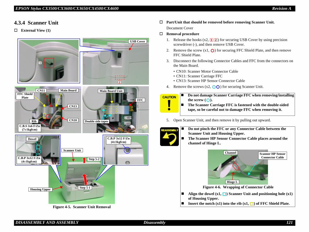
EPSON Stylus CX3500/CX3600/CX3650/CX4500/CX4600 Revision A
D 121
4.
ved before removing Scanner Unit.
) for securing USB Cover by using precision move USB Cover.
) for securing FFC Shield Plate, and then remove
onnector Cables and FFC from the connectors on
nnector Cable FFCr Connector Cable
) for securing Scanner Unit.
en remove it by pulling out upward.
F canner Carriage FFC when removing/installing
rriage FFC is fastened with the double-sided ul not to damage FFC when removing it.
FFC or any Connector Cable between the d Housing Upper. Sensor Connector Cable places around the
e L.
4-6. Wrapping of Connector Cable
(x1, ) Scanner Unit and positioning hole (x1) r.
(x1) into the rib (x1, ) of FFC Shield Plate.
2
Scanner HP SensorConnector Cable
Hinge L
Channel
ISASSEMBLY AND ASSEMBLY Disassembly
3.4 Scanner UnitExternal View (1)
Figure 4-5. Scanner Unit Removal
Part/Unit that should be remoDocument Cover
Removal procedure1. Release the hooks (x2,
screwdriver (-), and then re2. Remove the screw (x1,
FFC Shield Plate.3. Disconnect the following C
the Main Board.• CN10: Scanner Motor Co• CN11: Scanner Carriage• CN13: Scanner HP Senso
4. Remove the screws (x2,
5. Open Scanner Unit, and th
USB Cover
2
1
CN10
CN13
CN11 Main BoardFC Shield
Plate
C.B.S 3x6 F/Zn(7±1kgfcm)
Rib
FFC
Main Board Unit
Double side tapes
Step 5-1
Step 5-2C.B.P 3x12 F/Zn(4±1kgfcm)
Dowel C.B.P 3x12 F/Zn(4±1kgfcm)
Scanner Unit
Housing Upper
Do not damage S
the screw ( ). The Scanner Ca
tape, so be caref
Do not pinch theScanner Unit an
The Scanner HPchannel of Hing
Figure
Align the dowel of Housing Uppe
Insert the notch
1

EPSON Stylus CX3500/CX3600/CX3650/CX4500/CX4600 Revision A
D 122
emoval
) for securing Hinge R, and then remove Hinge R
) for securing Scanner Housing Upper.
r securing Scanner Housing Upper by using a move Scanner Housing Upper by lifting upward.
g steps in a location free of dirt and dust. n bench is preferred.
ocument Glass of Scanner Housing Upper.
) of Scanner Housing Lower with the notch sing Upper.
ISASSEMBLY AND ASSEMBLY Disassembly
External View (2)
Figure 4-7. Scanner Housing Upper Removal
Scanner Housing Upper R
1. Remove the screw (x1, from Scanner Unit.
2. Remove the screws (x6,
3. Release the ribs (x3, ) foscrewdriver (-), and then re
Ribs
Scanner Housing Upper
Document Glass
Hinge RC.B.P 3x10 F/Ni
(7±1kgfcm)
Hook
C.B.P 3x10 F/Zn(5±1kgfcm)
Perform the followinA clean room or clea
Do not damage the D
Align the hook (x1, (x1) of Scanner Hou

EPSON Stylus CX3500/CX3600/CX3650/CX4500/CX4600 Revision A
D 123
emoval
it to the center.
elt from Combination Gear 22.8, 7.762 and Driven
ge FFC from Scanner Carriage Unit, and then nit with Timing Belt.
S
ns Array when removing Scanner Carriage
. Handling of Scanner Carriage Unit
e FFC is fastened with the double-sided tape, so age FFC.
Rod Lens Array
ISASSEMBLY AND ASSEMBLY Disassembly
External View (3)
Figure 4-8. Scanner Carriage Unit Removal (1)
Scanner Carriage Unit R
1. Move Scanner Carriage Un
2. Release Scanner Timing BHolder.
3. Disconnect Scanner Carriaremove Scanner Carriage U
Driven Holder
1
3
Scanner Carriage Unit
Combination Gear 22.8, 7.7622
Scanner Timing Belt
canner Carriage Shaft
RibDouble side tape
Connector
Do not touch Rod LeUnit.
Figure 4-9
The Scanner Carriagbe careful not to dam

EPSON Stylus CX3500/CX3600/CX3650/CX4500/CX4600 Revision A
D 124
nner CR Holder with opening and shifting it to the
rom Scanner CR Holder.
for securing Belt Clamp by using a tweezers.
Scanner Carriage Unit.
y fastening the leg of CIS Spring to the dowel R Holder.
n Timing Belt having the teeth on both sides into nit.
4-11. Installation of Timing Belt
canner Carriage Shaft for a new one, always the specified portions.
r 6, Figure 6-4 (p.177)
ISASSEMBLY AND ASSEMBLY Disassembly
External View (4)
Figure 4-10. Scanner Carriage Unit Removal (2)
4. Remove CIS Unit from Scaright direction.
5. Remove CIS Spring (x2) f
6. Release the hooks (x2, )
7. Remove Timing Belt from
Belt Clamp
Timing Belt
Hook
Hook
Scanner CR HolderCIS Spring CIS Spring
ShaftsCIS Unit
Leg
Dowel
Bottom side
Install CIS Spring b(x1, ) of Scanner C
Install the location oScanner Carriage U
Figure
After changing the Sapply grease G-26 to Refer to Chapte

EPSON Stylus CX3500/CX3600/CX3650/CX4500/CX4600 Revision A
D 125
F
ner HP Sensor/Driven Holder Removal
it to the center.
elt from Combination Gear 22.8, 7.762 and Driven
L from the socket of Scanner Housing Lower.
nnector Cable and Scanner HP Sensor Connector nge L, and then pull from the notch of Scanner
) for securing Scanner HP Sensor, and then remove
nnector Cable and Scanner HP Sensor Connector anner Housing Lower while holding Scanner
) for securing Scanner Motor Unit, and then it.
ring from Scanner Housing Lower by using a
r Connector Cable and Scanner HP Sensor shown by figure.
hole (x1, ) of Scanner HP Sensor with the r Housing Lower.
holes (x2) of Scanner Motor Unit with the anner Housing Lower.
r Spring into the rib of Driven Holder.
ISASSEMBLY AND ASSEMBLY Disassembly
External View (5)
igure 4-12. Scanner Motor Unit/Scanner HP Sensor/Driven Holder Removal
Scanner Motor Unit/Scan
1. Move Scanner Carriage Un
2. Release Scanner Timing BHolder.
3. Release the shaft of Hinge
4. Release Scanner Motor CoCable from the hook of HiHousing Lower.
5. Remove the screw (x1, Scanner HP Sensor.
6. Release Scanner Motor CoCable from the hook of ScCarriage Shaft.
7. Remove the screws (x2, remove Scanner Motor Un
8. Remove Driven Holder Sptweezers.
1
3
Driven Holder
Combination Gear 22.8, 7.7622
Scanner Timing Belt
Hinge L Scanner Motor Connector Cable
Notch
Hook
Scanner HP SensorConnector Cable
Scanner HP Sensor
C.B.P 3x8 F/Zn (5±1kgfcm)Dowel
Shaft
Scanner Motor Unit
C.B.P 3x8 F/Zn (5±1kgfcm)Dowels
Rib
Driven Holder Spring
Place Scanner MotoConnector Cable as
Align the positioningdowel (x1) of Scanne
Align the positioningdowels (x2, ) of Sc
Insert Driven Holde

EPSON Stylus CX3500/CX3600/CX3650/CX4500/CX4600 Revision A
D 126
4.
ved before removing Panel Unit.t
anel Unit by using a precision screwdriver (-).
) for securing Panel Unit.
of Panel Unit in order shown by figure.
nnector (CN12) of Main Board, and then remove
securing Panel Board, and then remove Panel Board.
tor (CN1) of Panel Board.
py-Button and Power-Button from Panel Housing. quipped with 5 S-Buttons.)
PS
PU
nel Sheet, free it by inserting the screwdriver at he figure.
et to Panel Unit.
) of Panel Unit with the notches (x3, ) of
el Unit, Panel FFC will be hard to insert when Panel Board side (CN1).
holes (x2) of Panel Board with the dowels (x2, .
ISASSEMBLY AND ASSEMBLY Disassembly
3.5 Panel UnitExternal View
Figure 4-13. Panel Unit Removal
Part/Unit that should be remoDocument Cover / Scanner Uni
Removal procedure1. Peel off Panel Sheet from P
2. Remove the screws (x3,
3. Release the hooks (x3, )
4. Release Panel FFC from coPanel Unit.
5. Release the hooks (x2, )
6. Remove FFC from connec
7. Remove S-Buttons (x4), Co(Stylus CX4500/CX4600 e
Panel FFC
CN12
HooksNotches
anelheet
anelnit
Screwdriver insertion position
12
Panel Board
C.B.S 3x6 F/Zn(7±1kgfcm)
CN1Panel FFC
Power-ButtonCopy-Button
S-Buttons
Hooks
Dowels
When peeling off Pathe place shown by t
Paste new Panel She
Align the hooks (x3,Housing Upper.
When removing Pandisconnecting it from
Align the positioning) of Panel Housing

EPSON Stylus CX3500/CX3600/CX3650/CX4500/CX4600 Revision A
D 127
4.
ved before removing Housing Upper.
rt Assy. / Scanner Unit / Panel Unit
) securing Housing Upper.
securing Housing Upper by using a common ve by lifting upward.
fastened with the screws (1 each). S-Locks (x2), align the positioning hole of each Housing Upper dowels (x2).
n order shown by figure.
ISASSEMBLY AND ASSEMBLY Disassembly
3.6 Housing UpperExternal View
Figure 4-14. Housing Upper Removal
Part/Unit that should be remo
Document Cover / Paper Suppo
Removal procedure
1. Remove the screws (x6,
2. Release the hooks (x2) forscrewdriver, and then remo
1
6
S-Lock
C.B.P 3x10 F/Zn(4±1kgfcm)
2
S-Lock
C.B.P 3x10 F/Zn(4±1kgfcm)
3
4
5
Hooks
Dowels
C.B.P 3x10 F/Zn (4±1kgfcm)C.B.S 3x6 F/Zn (7±1kgfcm)
Dowels
S-Locks (x2) are When removing
S-Lock (x2) with
Tighten the screws i

EPSON Stylus CX3500/CX3600/CX3650/CX4500/CX4600 Revision A
D 128
4.
oved before removing Print Head.
rt Assy. / Scanner Unit / Panel Unit /
using a common screwdriver, and then slide nter.
from Carriage Unit.
r downward while releasing the lower tab (x1, ) ing a precision screwdriver (-).
or securing Sub FFC Guide by using a precision move Sub FFC Guide.
C
the hooks( ) of Carriage Unit can break.
FFC Guide into the notch of Carriage Unit.
-16. Installation of Sub FFC Guide
Rib
ISASSEMBLY AND ASSEMBLY Disassembly
3.7 Print HeadExternal View (1)
Figure 4-15. Print Head Removal (1)
Part/Unit that should be rem
Document Cover / Paper SuppoHousing Upper
Removal procedure
1. Release Carriage Lock by Carriage Unit center of pri
2. Remove all Ink Cartridges
3. Remove Head Cable Coveof Head Cable Cover by us
4. Release the hook (x1, ) fscrewdriver (-), and then re
Carriage Unit
arriage Lock
Sub FFC Guide
Hook
HooksRibsTabHead Cable Cover
Use caution because
Insert the rib of Sub
Figure 4

EPSON Stylus CX3500/CX3600/CX3650/CX4500/CX4600 Revision A
D 129
) for securing Print Head, and then lift Print Head
) from connectors (x2) of Print Head, and then
uch or damage the nozzles or the ink supply d.
ning holes (x2) of Print Head with the dowels age Unit.ws in order shown by figure.
mly into the connector of Print Head.
ed or replaced Print Head, implement the llowing order. (Refer to Chapter 5
eplacement only)for replacement only)justment
t
ent
ISASSEMBLY AND ASSEMBLY Disassembly
External View (2)
Figure 4-17. Print Head Removal (2)
5. Remove the screws (x3, by using a long-nose plier.
6. Disconnect Head FFCs (x2remove Print Head.
Print Head FFC
Connectors
Print Head C.B.P 2.5x8 F/Zn(3±1kgfcm)
Dowels
12
3
Use caution not to toneedles of Print Hea
Align the positio(x2, ) of Carri
Tighten the scre
Insert Head FFC fir
When having removadjustment in the fo“ADJUSTMENT”)1. PG Adjustment2. Ink charge (for r3. Input Head ID (4. Head angular ad5. Bi-D adjustmen6. PW adjustment7. First dot adjustm

EPSON Stylus CX3500/CX3600/CX3650/CX4500/CX4600 Revision A
D 130
4.
ved before removing Printer Mechanism.
rt Assy. / Scanner Unit / Panel Unit /
) for securing Rear Cover, and then remove Rear
m Housing Lower, grasp the handle of Tube s, and then carefully remove Waste Ink Tube (of sing both hands.
using a common screwdriver, and then move rinter.
R
C
2) of Housing Lower with the hooks (x2, ) of
ube may break when it is removed. If it breaks, em Unit.m Waste Ink Tube. Prepare cleaning rags be careful not spread ink onto surrounding
e of Waste Ink Tube with the position of Tube s shown by figure.ning hole (x1) of Housing Lower with the hook Ink Joint.
ISASSEMBLY AND ASSEMBLY Disassembly
3.8 Printer MechanismExternal View (1)
Figure 4-18. Printer Mechanism Removal (1)
Part/Unit that should be remo
Document Cover / Paper SuppoHousing Upper
Removal procedure
1. Remove the screws (x1, Cover.
2. Remove Eject Ink Joint froClamp and move it upwardInk System Unit side) by u
3. Release Carriage Lock by Carriage Unit to center of p
ear Cover
.B.P 3x10 F/Zn(4±1kgfcm) Housing Lower
Hooks
Carriage Unit
Carriage Lock
Waste Ink Tube
Tube ClampEject Ink Joint
Green line
Hook
Align the notches (xRear Cover.
The Waste Ink T
replace Ink Syst Ink may leak fro
beforehand, andarea.
Set the green linClamp handle a
Align the positio(x1, ) of Eject

EPSON Stylus CX3500/CX3600/CX3650/CX4500/CX4600 Revision A
D 131
) for securing Printer Mechanism.
able from the connector (CN1) of Main Board.
Mechanism while releasing dowel of Front Paper nel of) PG Lever by using a precision screwdriver Printer Mechanism from Housing Lower.
G
ws in order shown by figure.ning hole (x1) of Printer Mechanism with the Housing Lower.
position and lift Printer Mechanism upward e following step in order to prevent warping of
ter Mechanism into Housing Lower, insert Eject Ink Joint and firmly secure Waste Ink mp. Ink may leak if not properly installed.
ter Mechanism with a new component, be sure ft) of PF Roller Unit with a red circle.
in Board Unit with a refurbished unit, ller production value if the EEPROM cannot be Mechanism service parts are limited to IEI
igure 4-20. Marking position
king position
ISASSEMBLY AND ASSEMBLY Disassembly
External View (2)
Figure 4-19. Printer Mechanism Removal (2)
4. Remove the screws (x6,
5. Disconnect PS Connector C
6. Hold up left side of PrinterGuide Support from (Chan(-), and then remove whole
1
3
65
4
2
Printer Mechanism
CR Guide Frame
CN1
Main Board
PS Connector CablePG Lever
Dowel
Front Paperuide Support
Channel
C.B.P 3x8 F/Zn(4±1kgfcm)DowelHandling Position
Tighten the scre Align the positio
dowel (x1, ) of
Hold the designated when performing thMain Frame.
When installing PrinWaste Ink Tube intoTube with Tube Cla
When replacing Printo mark Bush 10 (LeWhen replacing Madetermine the PF Robacked up. (Printer products.)
F
Mar

EPSON Stylus CX3500/CX3600/CX3650/CX4500/CX4600 Revision A
D 132
ISASSEMBLY AND ASSEMBLY Disassembly
The assembled accuracy of each part composed of Printer mechanism is based on Housing Lower. To ensure the assembled accuracy, you have to control the assembled standard position of main frame against X/Y/Z-axis direction as the following figure. [X-axis direction]
Confirm that Printer Mechanism is properly placed in channel of Housing Lower and that there is no gap.
[Y-axis direction]Confirm that Printer Mechanism is properly placed in channel of Housing Lower and that there is no gap.
[Z-axis direction]Align positioning hole (x1) of Printer Mechanism with dowel (x1) of Housing Lower, and confirm that there is no gap.
Assembled standard position of Printer Mechanism
When having replaced Printer Mechanism, implement the following adjustment. (Refer to Chapter 5 "ADJUSTMENT")1. Initialize PF deterioration offset2. Disenable PF deterioration offset3. PF roller shaft manufacture code4. CR motor heat protection control
X-axis: 4 pointsY-axis: 1 pointZ-axis: 1 point

EPSON Stylus CX3500/CX3600/CX3650/CX4500/CX4600 Revision A
D 133
4.
ved before removing PS Board Unit.
rt Assy. / Scanner Unit / Panel Unit / nism
x2) for securing PS Connector Cable.
) for securing PS Board Unit, and then remove PS
into cavity of Housing Lower.tor Cable between the ribs of Housing Lower.ctor Cable projecting 40±2mm from the edge of
e of PS Connector Cable to the rear side of
ed PS Board Unit, implement the following o Chapter 5 “ADJUSTMENT”)rotection control
ISASSEMBLY AND ASSEMBLY Disassembly
3.9 PS Board UnitExternal View
Figure 4-21. PS Board Unit Removal
Part/Unit that should be remo
Document Cover / Paper SuppoHousing Upper / Printer Mecha
Removal procedure
1. Peel off the acetate tapes (
2. Remove the screw (x1, Board Unit.
Acetate tapes
C.B.P 3x10 F/Zn (4±1kgfcm)
Ferrite Core and Cavity
Ribs
PS Board Unit
40±2mmBlue line
Set Ferrite Core Place PS Connec Leave PS Conne
Housing Lower. Face the blue lin
Housing Lower.
When having replacadjustment. (Refer t CR motor heat p

EPSON Stylus CX3500/CX3600/CX3650/CX4500/CX4600 Revision A
D 134
4.
ved before removing Waste Ink Pads.
rt Assy. / Stacker / Scanner Unit / Panel Unit / nism
) for securing PG Lever Mounting Plate, and then , PG Lever Mounting Plate and Torsion Spring r.
long with Tube Clamp, Eject Ink Joint from the .
s from Housing Lower.
P
holes (x2) of PG Lever Mounting Plate with the ousing Lower.
of Waste Ink Tube straight ahead as shown by
ste Ink Tube into Housing Lower, insert into Lower and Eject Ink Joint, and firmly secure h Tube Clamp. Ink may leak if not properly
nk Pads into the ribs ( ) and the dowels ( )of
ISASSEMBLY AND ASSEMBLY Disassembly
3.10 Waste Ink PadsExternal View (1)
Figure 4-22. Waste Ink Pads Removal (1)
Part/Unit that should be remo
Document Cover / Paper SuppoHousing Upper / Printer Mecha
Removal procedure
1. Remove the screw (x1, remove together PG Lever19.01 from Housing Lowe
2. Remove Waste Ink Tube achannel of Housing Lower
3. Remove 14 Waste Ink Pad
RibsDowels
G Lever Mounting Plate
PG Lever Torsion Spring 19.01
Left side
C.B.P 3x8 F/Zn (4±1kgfcm)Dowels
Waste Ink Tubeand Channel
Tube Clamp
Eject Ink Joint
Align the positioningdowels (x2, ) of H
Set the leading pagefigure.
When installing Wachannel of Housing Waste Ink Tube witinstalled.
Properly set Waste IHousing Lower.

EPSON Stylus CX3500/CX3600/CX3650/CX4500/CX4600 Revision A
D 135
for securing Stacker Lock, and then remove sion Spring 5.1 from Housing Lower.
for securing PG Lever, and then remove PG Lever late.
.01 from the installation holes of PG Lever and PG then remove PG Lever and PG Lever Mounting
ottom of Housing Lower, and separate from
R
R
Stacker Lock through the channel of Housing
acker opens and closes smoothly.
ver operates smoothly.
ed Waste Ink Pads, implement the following o Chapter 5 “ADJUSTMENT”)ounter
ISASSEMBLY AND ASSEMBLY Disassembly
External View (2)
Figure 4-23. Stacker Lock/PG Lever/Foots Removal (2)
Stacker Lock Removal
1. Release the hooks (x2, )Stacker Lock and Compres
PG Lever Removal
1. Release the hooks (x2, )from PG Lever Mounting P
2. Remove Torsion Spring 19Lever Mounting Plate, andPlate.
Foots Removal
1. Remove Foots (x6) from bHousing Lower.
Hooks
Compression Spring 5.1ight side
Shaft and Channel
Stacker Lock
ight side
PG Lever
Torsion Spring 19.01HooksInstallation Holes
Foots
Pass the shaft ofLower.
Confirm that St
Confirm that PG Le
When having replacadjustment. (Refer t Waste ink pad c

EPSON Stylus CX3500/CX3600/CX3650/CX4500/CX4600 Revision A
D 136
4.
4.3
ved before removing Main Board Unit.
rt Assy. / Scanner Unit / Panel Unit / nism
1) for securing Head FFCs (x3).
tor Cable from the hooks (x2, ) of Main Board
1) for securing PE Sensor Cable Connector, and nnector Cable from the hooks (x2, ) of Main
able connectors and FFC from the connectors of
tor Cabletor Cable
or Cableor Cable
) for securing Main Board Unit, and then remove ter Mechanism.
M
C
2
into the slit of PF Encoder Sensor.2, ) of Main Frame into the hooks (x2) of t.
1, ) of Main Board Unit into the hook (x1) of
ning hole (x1) of Main Board Unit with the Main Frame.ws in order shown by figure.
ISASSEMBLY AND ASSEMBLY Disassembly
3.11 Main Board Unit
.11.1 Stylus CX3500/CX3600/CX3650External View
Figure 4-24. Main Board Unit Removal
Part/Unit that should be remo
Document Cover / Paper SuppoHousing Upper / Printer Mecha
Removal procedure
1. Peel off the acetate tape (x
2. Release PG Sensor ConnecUnit.
3. Peel off the acetate tape (xthen release PE Sensor CoBoard Unit.
4. Disconnect the following cMain Board.
• CN3: PE Sensor Connec• CN4: PG Sensor Connec• CN5: Head FFC• CN6: Head FFC• CN7: Head FFC• CN8: PF Motor Connect• CN9: CR Motor Connect
5. Remove the screws (x3, Main Board Unit from Prin
Head FFC Acetate tape
PG Sensor Connector Cable
ain Board Unit
Acetate tapePE Sensor Connector Cable
CN4CN3
CN8N9
C.B.S 3x6 F/Zn (7±1kgfcm)
1
3
Dowel
CN7
CN5
CN6
PF Encoder Sensor
PF Scale
Slit
HooksRibsRib
Hooks
Insert PF Scale Insert the ribs (x
Main Board Uni Insert the rib (x
Main Frame. Align the positio
dowel (x1, ) of Tighten the scre

EPSON Stylus CX3500/CX3600/CX3650/CX4500/CX4600 Revision A
D 137
ed Main Board Unit, implement the adjustment r. (Refer to Chapter 5 “ADJUSTMENT”)
to read data from the old board]ata Copysor positioning adjustment
aft manufacture codele to read from the old board]sor positioning adjustment (for replacement
settingID adjustmentr adjustmentent
entjustmenteat protection control
ISASSEMBLY AND ASSEMBLY Disassembly
PF Scale Sensor positioning adjustmentUse the following procedure to confirm that PF Scale is positioned in the center of the PF Sensor.1. Test fit Main Board Unit, and confirm whether or not PF
Scale is positioned in the center of PF Sensor.2. If PF Scale is positioned in the center of PF Sensor,
adjustment is complete. If scale is not positioned in center of sensor, adjust position of PF Scale using spacer (0.5mm thickness) as shown in diagram below.
Figure 4-25. PF Scale Sensor positioning adjustment
Left side Right side
0.1 to1.0mm
Spacer
PF Scale
Spacer is not applied to Main Board Unit for service part. Place spacer between Shield
Board and Main Board. If PF Scale is off to the left,
remove the spacer. If PF Scale is off to the right,
add an additional spacer. (Total of 2 spacers)
When having replacin the following orde [When possible
1. EEPROM D2. PF Scale Sen3. PF roller sh
[When impossib1. PF Scale Sen
only)2. Destination 3. Input Head 4. Top margin5. Head angula6. Bi-D adjustm7. PW adjustm8. First dot ad9. CR motor h

EPSON Stylus CX3500/CX3600/CX3650/CX4500/CX4600 Revision A
D 138
4.3
ved before removing Main Board Unit.
rt Assy. / Scanner Unit / Panel Unit / nism
1) for securing Head FFCs (x3)
tor Cable from the hooks (x3, ) of Main Board
1) for securing PE Sensor Connector Cable, and nnector Cable from the hooks (x2, ) of Main
able connectors and FFC from the connectors of
tor Cabletor Cable
or Cableor Cable
) for securing Main Board Unit, and then remove ter Mechanism.
M
C
2
into the slit of PF Encoder Sensor.2, ) of Main Frame into the hooks (x2) of t.
1, ) of Main Board Unit into the hook (x1) of
ning hole (x1) of Main Board Unit with the Main Frame.ws of Main Board Unit in order shown by
ISASSEMBLY AND ASSEMBLY Disassembly
.11.2 Stylus CX4500/CX4600External View (1)
Figure 4-26. Main Board Unit Removal (1)
Part/Unit that should be remo
Document Cover / Paper SuppoHousing Upper / Printer Mecha
Removal procedure
1. Peel off the acetate tape (x
2. Release PG Sensor ConnecUnit.
3. Peel off the acetate tape (xthen release PE Sensor CoBoard Unit.
4. Disconnect the following cMain Board.
• CN3: PE Sensor Connec• CN4: PG Sensor Connec• CN5: Head FFC• CN6: Head FFC• CN7: Head FFC• CN8: PF Motor Connect• CN9: CR Motor Connect
5. Remove the screws (x3, Main Board Unit from Prin
PG Sensor Connector Cable
ain Board Unit
Head FFC
Acetatetape
Acetate tapePE Sensor Connector Cable
CN4CN3
CN8N9
C.B.S 3x6 F/Zn (7±1kgfcm)
1
3
Dowel
CN7
CN5
CN6
PF Scale
Slit
PF EncoderSensor Hooks
RibsRib
Hooks
Insert PF Scale Insert the ribs (x
Main Board Uni Insert the rib (x
Main Frame. Align the positio
dowel (x1, ) of Tighten the scre
figure.

EPSON Stylus CX3500/CX3600/CX3650/CX4500/CX4600 Revision A
D 139
) for securing Card Slot Unit, and then remove ain Board Unit.
ot Cover Spring from the hook (x1, ) of Card ove Card Slot Cover Spring.
of Card Slot Cover from Card Slot Housing, and er.
ning holes (x2, ) of Main Board Unit with the f Card Slot Housing.ws of Card Slot Unit in order shown by figure.
ver Spring as shown by figure.
Slot Cover into Card Slot Housing and then
ISASSEMBLY AND ASSEMBLY Disassembly
External View (2)
Figure 4-27. Main Board Unit Removal (2)
6. Remove the screws (x2, Card Slot Unit from and M
7. Release the foot of Card SlSlot Housing, and then rem
8. Release the dowel (x1, )then remove Card Slot Cov
Card Slot Unit
C.B.S 3x6 F/Zn (7±1kgfcm)
1 2
Card SlotCover Spring
Hook
Leg
Card SlotHousing
Card SlotCover
Shaft
Dowel
Installation of Card Slot Cover Spring
DowelsPositioning Holes
Align the positiodowels (x2, ) o
Tighten the scre
Install Card Slot Co
Set the shaft of Cardalign the dowel.

EPSON Stylus CX3500/CX3600/CX3650/CX4500/CX4600 Revision A
D 140
ed Main Board Unit, implement the adjustment r. (Refer to Chapter 5 “ADJUSTMENT”)
to read data from the old board]ata Copysor positioning adjustment
aft manufacture codele to read from the old board]sor positioning adjustment (for replacement
settingID adjustmentr adjustmentent
entjustmenteat protection control
ISASSEMBLY AND ASSEMBLY Disassembly
PF Scale Sensor positioning adjustmentUse the following procedure to confirm that PF Scale is positioned in the center of the PF Sensor.1. Test fit Main Board Unit, and confirm whether or not PF
Scale is positioned in the center of PF Sensor.2. If PF Scale is positioned in the center of PF Sensor,
adjustment is complete. If scale is not positioned in center of sensor, adjust position of PF Scale using spacer (0.5mm thickness) as shown in diagram below.
Figure 4-28. PF Scale Sensor positioning adjustment
Left side Right side
0.1 to1.0mm
Spacer
PF Scale
Spacer is not applied to Main Board Unit for service part. Place spacer between Shield
Board and Main Board. If PF Scale is off to the left,
remove the spacer. If PF Scale is off to the right,
add an additional spacer. (Total of 2 spacers)
When having replacin the following orde [When possible
1. EEPROM D2. PF Scale Sen3. PF roller sh
[When impossib1. PF Scale Sen
only)2. Destination 3. Input Head 4. Top margin5. Head angula6. Bi-D adjustm7. PW adjustm8. First dot ad9. CR motor h

EPSON Stylus CX3500/CX3600/CX3650/CX4500/CX4600 Revision A
D 141
4.
ved before removing ASF Unit.
rt Assy. / Scanner Unit / Panel Unit / nism
1) for securing PE Sensor Connector Cable to the , and then release PE Sensor Connector Cable from t and Main Board Unit.
/PF Motor Connector Cable from slot of ASF
) for securing ASF Unit, and then remove chanism.
ning hole (x1) of Main Frame with the dowel ) of ASF Unit.
of ASF Unit into the slot of Ink System Unit.ws in order shown by figure.
ISASSEMBLY AND ASSEMBLY Disassembly
3.12 ASF UnitExternal View (1)
Figure 4-29. ASF Unit Removal (1)
Part/Unit that should be remo
Document Cover / Paper SuppoHousing Upper / Printer Mecha
Removal procedure
1. Peel off the acetate tape (xshield plate of Main Boardhooks (x3, ) of ASF Uni
2. Remove Ferrite Core of CRUnit.
3. Remove the screws (x5, ASF Unit from Printer Me
Ferrite core (CR Motor) and SlotFerrite core (PF Motor) and Slot
1
4
5
2
3
ASF Unit
C.B.S 3x6 F/Zn (7±1kgfcm)C.B.S (P2) 3x6 F/Zn (7±1kgfcm)C.B.P 3x8 F/Zn (4±1kgfcm)Shaft
Ink System Unit
Front side
Rib
Hooks
Acetate tapeMain Board Unit
ASF Unit
Dowel
Align the positio(x1, )/rib (x1,
Insert the shaft Tighten the scre

EPSON Stylus CX3500/CX3600/CX3650/CX4500/CX4600 Revision A
D 142
ove Compression Spring 5.58.
lease the both ends of dowels (2 each, ) from e Paper Back Lever and Torsion Spring 6.45.
R
Spring 5.58 to into the ribs (x2, ) of ASF 1, ) of Hopper.
Roller and Hopper Pad.
leg of Torsion Spring 6.45 to the shaft of Paper then fasten short leg to the channel of ASF
per Back Lever operates smoothly.
SF Unit for a new one, always apply grease G-to the specified portions.r 6, Figure 6-5 (p.177)
ed or replaced ASF Unit, implement the llowing order. (Refer to Chapter 5
stmentent
ISASSEMBLY AND ASSEMBLY Disassembly
External View (2)
Figure 4-30. ASF Unit Removal (2)
4. Open Hopper, and then rem
5. Bend Paper Back Lever, reASF Unit, and then remov
Paper Back Lever
Dowels
Torsion Spring 6.45
Dowels
Compression Spring 5.58
Hopper
ASF Frame
Ribs
etard Roller
Hopper Pad
L-Shape Leg
Short Leg
Install CompressionFrame and the rib (x
Do not touch Retard
Fasten L-shape Back Lever, andUnit.
Confirm that Pa
After changing the A26 and grease G-46 Refer to Chapte
When having removadjustment in the fo“ADJUSTMENT”)1. Top margin adju2. First dot adjustm

EPSON Stylus CX3500/CX3600/CX3650/CX4500/CX4600 Revision A
D 143
4.
ved before removing Holder Shaft Unit.rt Assy. / Scanner Unit / Panel Unit / nism / ASF Unit
of printer.1) for securing PE Sensor Connector Cable from
nector Cable from connector (CN3) of Main Board.) for securing Holder Shaft Unit. from Main Frame as belows.) of Holder Shaft Unit, and pull Holder Shaft Unit ain Frame.
me position side slightly while holing the whole of pull the bottom of the unit toward the backside of
M
M
C
ttach PF Sensor Connector Cable to printed line ame.
4-32. Installation of Timing Belt
ur by placing a load on lower side hook (x1, ) if Pump Frame is spread too wide. Roller.age to gear surface of Spur Gear 36.82 and
ar 27.2, 19.2. Sensor Lever to be damaged by interference e Rear.
ever into notch of Paper Guide Rear.faces of Spur Gear 36.8 and Combination Gear
ning hole (x1) of Ink System with the dowel (x1, aft Unit.haft Unit with hooks (x6, ) and ribs (x2, ).
Printed Lines(Installation Position)
ISASSEMBLY AND ASSEMBLY Disassembly
3.13 Holder Shaft UnitExternal View (1)
Figure 4-31. Holder Shaft Unit Removal (1)
Part/Unit that should be remoDocument Cover / Paper SuppoHousing Upper / Printer Mecha
Removal procedure1. Slide Carriage Unit center 2. Peel off the acetate tape (x
Main Frame.
3. Disconnect PE Sensor Con4. Remove the screw (x1, 5. Remove Holder Shaft Unit
1. Push the hooks (x2, upward slightly from M
2. Move Pump Unit to hoHolder Shaft Unit, andthe printer.Holder Shaft Unit
LD Roller
CN3
PE Sensor Connector Cable
ain Frame
ain Board Unit
Acetate tape
C.B.S 3x6 F/Zn (7±1kgfcm)
Front side HooksRibs
11
DowelPump Frame
Spur Gear 36.8
ombinationGear
27.2, 19.2
Paper Guide Rear
PE Sensor Lever and Notch
Hook
Use acetate tape to aposition on Main Fr
Figure
Damage may occ
of Pump Frame Do not touch LD Do not allow dam
Combination Ge Do not allow PE
with Paper Guid
Set PE Sensor L Engage gear sur
27.2, 19.2. Align the positio
) of Holder Sh Secure Holder S
1

EPSON Stylus CX3500/CX3600/CX3650/CX4500/CX4600 Revision A
D 144
r securing Paper Block to Holder Shaft, and then
long with Clutch mechanism from Holder Shaft.
om LD Roller Shaft.
0.143, and remove Clutch from LD Roller Shaft.S
Pf Paper Block with shafts (x2, ) of Holder
n Spring 137.7 to press cam of LD Roller Shaft.g hole (x2) of Holder Shaft with dowel (x2, ) of .
mechanism operates smoothly.
g hole (x1) of Clutch with dowel (x1, ) of LD
Spring 0.143 in the correct condition as shown
ISASSEMBLY AND ASSEMBLY Disassembly
External View (2)
Figure 4-33. Holder Shaft Unit Removal (2)
6. Release dowels (x2, ) foremove Paper Block.
7. Remove LD Roller Shaft a
8. Remove Spur Gear 36.8 fr
9. Remove Extension Spring pur Gear 36.8
Clutch Extension Spring 0.143
Hooks
Dowels
LD Roller Shaft
Holder Shaft
Torsion Spring 137.7
Cam
aper Block
Dowels
Shafts
Dowel
O.K.
N.G.
Align notches (x2) oShaft.
Use leg of Torsio Align positionin
LD Roller Shaft
Confirm that Clutch
Align positioninRoller Shaft.
Install Extensionby figure.

EPSON Stylus CX3500/CX3600/CX3650/CX4500/CX4600 Revision A
D 145
figure, remove shaft of PE Sensor Lever from ove PE Sensor Lever and Torsion Spring 0.22.
22 from PE Sensor Lever.
tor Cable from channel of Holder Shaft.
ecuring PE sensor, and then remove PE sensor
leg of Torsion Spring 0.22 to indentation of PE d fasten straight leg to Holder Shaft. Sensor Lever operates smoothly.
nnector Cable so it will not protrude from haft.
ed or replaced Holder Shaft Unit, implement e following order. (Refer to Chapter 5
stment
ISASSEMBLY AND ASSEMBLY Disassembly
External View (3)
Figure 4-34. Holder Shaft Unit Removal (3)
10. Following order shown byHolder Shaft, and then rem
11. Remove Torsion Spring 0.
12. Release PE sensor Connec
13. Release hook (x1, ) for sfrom Holder Shaft.
PE Sensor Lever
ShaftShaft
1
2
Straight Leg
L-Shape Leg
Torsion Spring 0.22
PE Sensor Connector Cable
Channel
PE Sensor Hook
Fasten L-shapedSensor Lever, an
Confirm that PE
Wrap PE Sensor Cochannel of Holder S
When having removthe adjustment in th“ADJUSTMENT”) Top margin adju
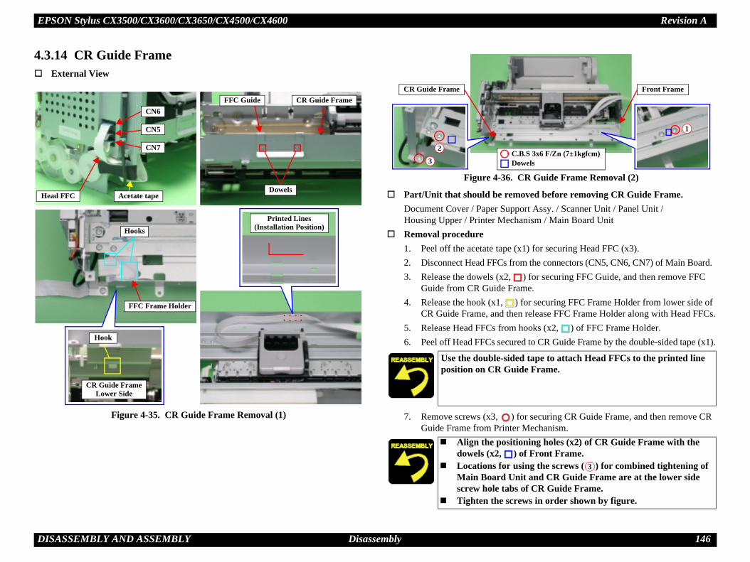
EPSON Stylus CX3500/CX3600/CX3650/CX4500/CX4600 Revision A
D 146
4.
R Guide Frame Removal (2)
ved before removing CR Guide Frame.rt Assy. / Scanner Unit / Panel Unit / nism / Main Board Unit
1) for securing Head FFC (x3). the connectors (CN5, CN6, CN7) of Main Board.
) for securing FFC Guide, and then remove FFC e.
or securing FFC Frame Holder from lower side of release FFC Frame Holder along with Head FFCs.ooks (x2, ) of FFC Frame Holder.d to CR Guide Frame by the double-sided tape (x1).
r securing CR Guide Frame, and then remove CR Mechanism.
H
tape to attach Head FFCs to the printed line e Frame.
ning holes (x2) of CR Guide Frame with the f Front Frame.ing the screws ( ) for combined tightening of t and CR Guide Frame are at the lower side
of CR Guide Frame.ws in order shown by figure.
1
.S 3x6 F/Zn (7±1kgfcm)wels
Front Frame
3
ISASSEMBLY AND ASSEMBLY Disassembly
3.14 CR Guide FrameExternal View
Figure 4-35. CR Guide Frame Removal (1)
Figure 4-36. C
Part/Unit that should be remoDocument Cover / Paper SuppoHousing Upper / Printer Mecha
Removal procedure1. Peel off the acetate tape (x2. Disconnect Head FFCs from3. Release the dowels (x2,
Guide from CR Guide Fram4. Release the hook (x1, ) f
CR Guide Frame, and then5. Release Head FFCs from h6. Peel off Head FFCs secure
7. Remove screws (x3, ) foGuide Frame from Printer
ead FFC Acetate tape
CN7
CN5
CN6FFC Guide
Dowels
CR Guide Frame
FFC Frame Holder
Hooks
Hook
CR Guide FrameLower Side
Printed Lines(Installation Position)
Use the double-sidedposition on CR Guid
Align the positiodowels (x2, ) o
Locations for usMain Board Uniscrew hole tabs
Tighten the scre
2
3C.BDo
CR Guide Frame

EPSON Stylus CX3500/CX3600/CX3650/CX4500/CX4600 Revision A
D 147
4.
oved before removing CR Motor.
rt Assy. / Scanner Unit / Panel Unit / nism / Main Board Unit / CR Guide Frame
of printer.
1) from CR Motor, and then release CR Motor otor Connector Cable.
of CR Motor Connector Cable from the slot (x1) of
Belt by pressing Driven Pulley Holder in the y figure, and then remove Timing Belt from the
) for securing CR Motor, and then remove CR nism.
n gear of CR Motor.
t recorded Lot Number faces upward.ws in order shown by figure.there is no gap between CR Motor and Main
ed or replaced CR Motor, implement the llowing order. (Refer to Chapter 5
t
entrotection control (for replacement only)
ISASSEMBLY AND ASSEMBLY Disassembly
3.15 CR MotorExternal View
Figure 4-37. CR Motor Removal
Part/Unit that should be rem
Document Cover / Paper SuppoHousing Upper / Printer Mecha
Removal procedure
1. Slide Carriage Unit center
2. Peel off the acetate tape (xConnector Cable and PF M
3. Remove Ferrite Core (x1) ASF Unit.
4. Loosen tension of Timing direction of arrow shown bpinion gear of CR Motor.
5. Remove the screws (x2, Motor from Printer Mecha
Ferrite Core and Slot
Acetate tape
CR Motor
Driven Pulley HolderTiming BeltPinion gear
C.P 3x4 F/Zn (4±0.5kgfcm)
12
Lot No.
Do not damage pinio
Assemble so tha Tighten the scre Make sure that
Frame.
When having removadjustment in the fo“ADJUSTMENT”)1. Bi-D adjustmen2. PW adjustment3. First dot adjustm4. CR motor heat p

EPSON Stylus CX3500/CX3600/CX3650/CX4500/CX4600 Revision A
D 148
4.
oved before removing PF Motor.
rt Assy. / Scanner Unit / Panel Unit / nism / Main Board Unit
1) from CR Motor, and then release CR Motor otor Connector Cable.
of PF Motor Connector Cable from the slot (x1) of
o Spur Gear 32.4 with the double-sided tape (x1).
or securing Spur Gear 30.8, and then remove Spur e.
) for securing PF Motor, and then remove PF nism.
F
C
S
ollowing locations.F Motor
t label with recorded Lot Number faces upward.there is no gap between PF Motor and Main
ISASSEMBLY AND ASSEMBLY Disassembly
3.16 PF MotorExternal View
Figure 4-38. PF Motor Removal
Part/Unit that should be rem
Document Cover / Paper SuppoHousing Upper / Printer Mecha
Removal procedure
1. Peel off the acetate tape (xConnector Cable and PF M
2. Remove Ferrite Core (x1) ASF Unit.
3. Peel off PF Scale secured t
4. Remove Spacer (4.1x0.5) fGear 30.8 from Main Fram
5. Remove the screws (x2, Motor from Printer Mecha
PF Motor
C.P 3x4 F/Zn (4±0.5kgfcm)
errite Coreand Slot
Acetate tapeR Motor
PF Scale
Doublesidetape
Spur Gear 32.4
Spur Gear 30.8pacer (4.1x0.5)
Pinion gear Lot No. Do not damage the f Pinion gear of P PF Scale Spur Gear 30.8
Assemble so tha Make sure that
Frame.

EPSON Stylus CX3500/CX3600/CX3650/CX4500/CX4600 Revision A
D 149
4.
ved before removing Carriage Unit.
rt Assy. / Scanner Unit / Panel Unit / nism / Main Board Unit / CR Guide Frame /
Driven Pulley Holder.
ain Frame.
o Spur Gear 32.4 with the double-sided tape (x1).
or securing Spur Gear 30.8, and then remove Spur e.
orsion Spring from the hooks (x2, ) of Main R Guide Shaft Torsion Spring from Main Frame.
H
S
llowing points. Scale with bare hands.R Scale.
tension Spring 3.289 in a way that does not
g 3.289 should not be twisted. so that it passes through the slit of CR Encoder
d of CR Scale so that the cut section faces
llowing points. Scale with bare hands.F Scale.
be unsteady.
ISASSEMBLY AND ASSEMBLY Disassembly
3.17 Carriage UnitExternal View (1)
Figure 4-39. Carriage Unit Removal (1)
Part/Unit that should be remo
Document Cover / Paper SuppoHousing Upper / Printer MechaCR motor
Removal procedure
1. Release Timing Belt from
2. Remove CR Scale from M
3. Peel off PF Scale secured t
4. Remove Spacer (4.1x0.5) fGear 30.8 from Main Fram
5. Release CR Guide Shaft TFrame, and then remove C
Driven Pulley HolderTiming Belt
CR Scale Hook
Extension Spring 3.289
ook
Notch Location
CR Encoder Sensor Slot
pacer (4.1x0.5)
Spur Gear 30.8 PF Scale
Left sideDouble side
tapeSpur Gear 32.4
CR Guide ShaftTorsion Spring
Installation Hole
Hooks
Be cautious of the fo Do not touch CR Do not damage C Handle leg of Ex
extend it.
Extension Sprin Install CR Scale
Sensor. Install the left en
upward.
Be cautious of the fo Do not touch PF Do not damage P
PF Scale should not

EPSON Stylus CX3500/CX3600/CX3650/CX4500/CX4600 Revision A
D 150
for securing Parallel Adjustment Lever (Left), and tment Lever (Left) from Main Frame while lifting Shaft upward.
ressing Spring from the hook (x1, ) of Main R Guide Shaft Pressing Spring from Main Frame.
Carriage Guide Shaft from Printer Mechanism as
e Guide Shaft and shift in left direction until arriage Guide Shaft from the notch of Main Frame.
e Shaft along with Carriage Unit from Main Frame.
aft from Carriage Unit.
al
the connector of CR Encoder Board, and then pull tch of Carriage.
) for securing CR Encoder Board, and then remove
hole (x1) of Parallel Adjustment Lever (Left) ) of Main Frame.
arriage Guide Shaft.Timing Belt with the grease (KEN Grease).
ge Unit operates smoothly.
Encoder Board to float.ning holes (x2) of CR Encoder Board with the f Carriage.
ISASSEMBLY AND ASSEMBLY Disassembly
External View (2)
Figure 4-40. Carriage Unit Removal (2)
6. Remove the screw (x1, )then remove Parallel Adjusleft end of Carriage Guide
7. Release CR Guide Shaft PFrame, and then remove C
8. Remove Carriage Unit andfollows.1. Lift left end of Carriag
releasing right end of C
2. Remove Carriage Guid
9. Pull out Carriage Guide Sh
CR Encoder Board Remov
1. Disconnect Head FFC fromout Head FFC from the no
2. Remove the screws (x2, CR Encoder Board.
Right side
CR Guide ShaftPressing Spring
HookParallel AdjustmentLever (Left)
CR Guide Shaft
C.B.S 3x6 F/Zn (7±1kgfcm)Dowel
Carriage Unit
2
1 1'
CR Encoder Board Connector
C.B.P (P1) 1.7x5 F/ZB(2±0.5kgfcm) Dowels
Notch
Head FFC
Align the positioningwith the dowel (x1,
Do not damage C Do not stain the
Confirm that Carria
Do not allow CR Align the positio
dowels (x2, ) o

EPSON Stylus CX3500/CX3600/CX3650/CX4500/CX4600 Revision A
D 151
l
) for securing PW Sensor Cap, and then remove
the connector of PW Sensor Board, and then pull tch of Carriage.
arriage Unit.
e notch of Carriage.
e hooks (x4, ) for securing Head FFC.
the connector of CSIC board.
nsor Cap to float.
arriage Unit for a new one, always apply pecified portions.r 6, Figure 6-7 (p.178)
ed Carriage Unit, implement the adjustment in (Refer to Chapter 5 “ADJUSTMENT”)
stmentjustment
t
ent
ISASSEMBLY AND ASSEMBLY Disassembly
External View (3)
Figure 4-41. Carriage Unit Removal (3)
PW Sensor Board Remova
1. Remove the screw (x1, PW Sensor Cap.
2. Disconnect Head FFC fromout Head FFC from the no
Head FFC Removal
1. Remove Print Head from C
2. Pull out Head FFC from th
3. Release Head FFC from th
4. Disconnect Head FFC from
PW Sensor Board
Connector
Head FFCNotch
PW Sensor CapC.B.P (P1) 1.7x5 F/ZB(2±0.5kgfcm)
HooksNotch
Connector
Do not allow PW Se
After changing the Cgrease KEN to the s Refer to Chapte
When having replacthe following order. 1. PG Adjustment2. Top margin adju3. Head angular ad4. Bi-D adjustmen5. PW adjustment6. First dot adjustm

EPSON Stylus CX3500/CX3600/CX3650/CX4500/CX4600 Revision A
D 152
4.
ved before removing Paper Guide Upper Unit.
rt Assy. / Scanner Unit / Panel Unit / inter Mechanism / Main Board Unit /
Carriage Unit
, ) for securing Paper Guide Upper Unit (x3), ide Upper Unit (x3) along with Torsion Spring Frame.
r Guide Upper UnitSpring 75.35 onto Paper Guide Upper Unit. place hooks (x2, ) of Paper Guide Upper ain Frame in order shown by figure.il section of Torsion Spring 75.35 into the rib.sitioning holes (x2) of Main Frame with the
) of Paper Guide Upper Unit, and then set e Upper Unit along with Torsion Spring 75.35. section of Torsion Spring 75.35 toward the he margin at approximately 1~1.5mm, and then p with Paper Guide Upper Unit.
ed or replaced Paper Guide Upper Unit, tment in the following order. (Refer to Chapter )stment
ISASSEMBLY AND ASSEMBLY Disassembly
3.18 Paper Guide Upper UnitExternal View
Figure 4-42. Paper Guide Upper Unit Removal
Part/Unit that should be remo
Document Cover / Paper SuppoHousing Upper / Print Head/ PrCR Guide Frame / CR motor /
Removal procedure
1. Set an OHP sheet.
2. Release the dowels (2 eachand then remove Paper Gu75.35 (1 each) from Main
OHP sheet
Paper Guide Upper Units
12
Torsion Spring 75.35
DowelsHooksRib
Approx. 1~1.5mm
Reassembly of Pape1. Set Torsion 2. Temporarily
Unit onto M3. Insert the co4. Align the po
dowels (x2, Paper Guid
5. Pull the coilfront, hold teliminate ga
When having removimplement the adjus5 “ADJUSTMENT” Top margin adju

EPSON Stylus CX3500/CX3600/CX3650/CX4500/CX4600 Revision A
D 153
4.
oved before removing Front Frame.
rt Assy. / Scanner Unit / Panel Unit / inter Mechanism / Main Board Unit /
Carriage Unit
) for securing Front Frame, and then remove Front nism.
ning holes of Front Frame with the ribs (x3, )
ws in order shown by figure.
Front Frame for new one, always apply grease portion.
r 6, Figure 6-10 (p.179)
ed or replaced Front Frame, implement the llowing order. (Refer to Chapter 5
tent
ISASSEMBLY AND ASSEMBLY Disassembly
3.19 Front FrameExternal View
Figure 4-43. Front Frame Removal
Part/Unit that should be rem
Document Cover / Paper SuppoHousing Upper / Print Head/ PrCR Guide Frame / CR motor /
Removal procedure
1. Remove the screws (x3, Frame from Printer Mecha
2
1
3
Front Frame
C.B.S 3x6 F/Zn (7±1kgfcm)Ribs
EJ Frame Unit
Align the positioof Main Frame.
Tighten the scre
When changing the KEN to the specified Refer to Chapte
When having removadjustment in the fo“ADJUSTMENT”)1. Bi-D adjustmen2. First dot adjustm

EPSON Stylus CX3500/CX3600/CX3650/CX4500/CX4600 Revision A
D 154
4.
ved before removing EJ Frame Unit.
rt Assy. / Scanner Unit / Panel Unit / inter Mechanism / Main Board Unit /
Carriage Unit / Front Frame
1) for securing PG Sensor Connector Cable.
ing from the left end of EJ Frame Unit.
the left Bush 5 of EJ Frame Unit, and rotate
Bush 5 at right end of EJ Frame Unit, and allow to rd) 90°.
for securing EJ Frame Unit while lifting the front ard.
rame Unit while handling Printer Mechanism
rubber portion.
t/right Bush 5 into the notches of Main Frame.
ure 4-45. Installation of Bush 5
there is no gap between EJ Frame Unit and
e Right side
ISASSEMBLY AND ASSEMBLY Disassembly
3.20 EJ Frame UnitExternal View (1)
Figure 4-44. EJ Frame Unit Removal (1)
Part/Unit that should be remo
Document Cover / Paper SuppoHousing Upper / Print Head/ PrCR Guide Frame / CR motor /
Removal procedure
1. Peel off the acetate tape (x
2. Remove EJ Grounding Spr
3. Release dowel (x1, ) of downward 90°.
4. Release dowel (x1, ) of rotate upward (or downwa
5. Release the hooks (x3, )side of EJ Frame Unit upw
Right sideBush 5Left side
Bush 5
Acetate tape
EJ Grounding Spring
Hooks
Do not hold FJ F
in your repair. Do not touch the
Firmly insert lef
Fig
Make sure that Main Frame.
Left sid
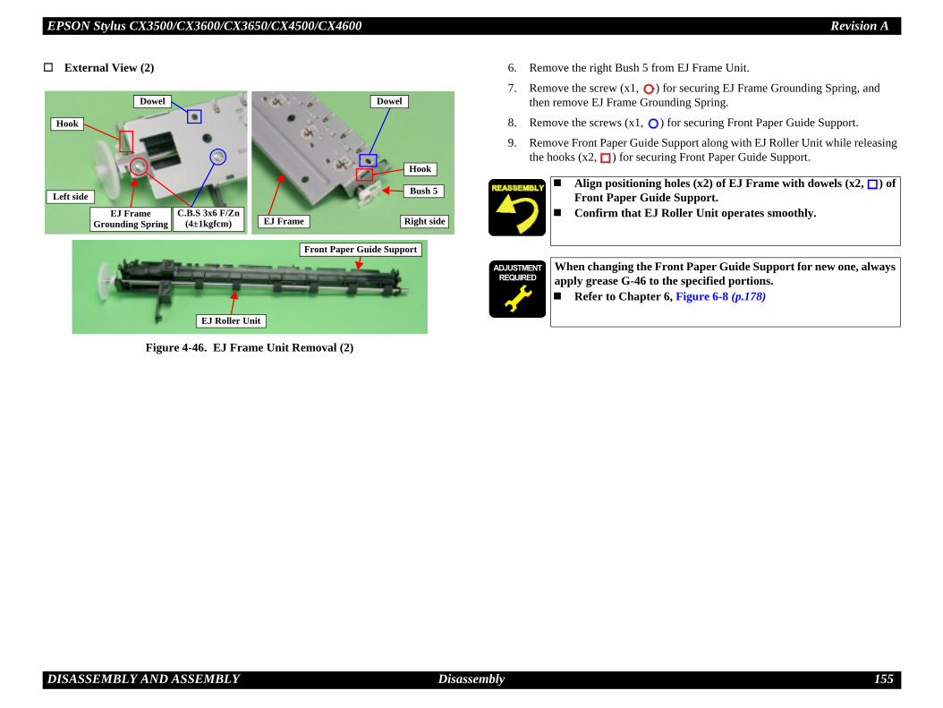
EPSON Stylus CX3500/CX3600/CX3650/CX4500/CX4600 Revision A
D 155
rom EJ Frame Unit.
) for securing EJ Frame Grounding Spring, and unding Spring.
) for securing Front Paper Guide Support.
Support along with EJ Roller Unit while releasing ring Front Paper Guide Support.
Lg holes (x2) of EJ Frame with dowels (x2, ) of ide Support. Roller Unit operates smoothly.
Front Paper Guide Support for new one, always the specified portions.
r 6, Figure 6-8 (p.178)
ISASSEMBLY AND ASSEMBLY Disassembly
External View (2)
Figure 4-46. EJ Frame Unit Removal (2)
6. Remove the right Bush 5 f
7. Remove the screw (x1, then remove EJ Frame Gro
8. Remove the screws (x1,
9. Remove Front Paper Guidethe hooks (x2, ) for secu
Right side
Bush 5
Hook
Dowel
EJ Frame
eft side
Hook
Dowel
C.B.S 3x6 F/Zn(4±1kgfcm)
EJ FrameGrounding Spring
Front Paper Guide Support
EJ Roller Unit
Align positioninFront Paper Gu
Confirm that EJ
When changing the apply grease G-46 to Refer to Chapte

EPSON Stylus CX3500/CX3600/CX3650/CX4500/CX4600 Revision A
D 156
4.
ved before removing Ink System Unit.rt Assy. / Scanner Unit / Panel Unit / inter Mechanism / Main Board Unit / CR Guide Frame / CR motor / Carriage Unit /
nder Cap Frame.
) for securing Cap Unit.me interior, and then release the hooks (x2, ) of
e.
for securing Pump Unit to Main Frame carefully, h supporting Change Lever and Combination Gear Supporting of Change Lever and gear is to prevent assembly.)ystem Unit from Printer Mechanism, and remove p Pulley.
CL
age by touching Sealing Rubber or Head rforming the following steps.tion location before removing Ink Tube.
Tube into groove.
holes (x2) of Main Frame with the dowels (x2,
ning holes (x3) of Main Frame with the dowels Unit and the dowel (x1, ) of Spur Gear 27.2.p Unit operates smoothly.
ISASSEMBLY AND ASSEMBLY Disassembly
3.21 Ink System UnitExternal View
Figure 4-47. Ink System Unit Removal
Part/Unit that should be remoDocument Cover / Paper SuppoHousing Upper / Print Head/ PrASF Unit / Holder Shaft Unit / Front Frame
Removal procedure
1. Release Ink Tube located u
2. Remove the screw (x1, 3. Slide Cap Unit to Main Fra
Cap Unit from Main Fram
4. Release the hooks (x3, )and remove Pump Unit wit27.2, 19.2 by your finger. (damage by dropping in dis
5. Remove the whole of Ink Sthe gears (x4) and the Pum
Dowels
Right side
C.B.P 3x8 F/Zn (4±1kgfcm)Sealing RubberHead Cleaner
Right bottom sideHooks
Cap Unit GrooveHook
Pump Unit
hangeever
DowelDowels
Spur Gear27.2
Hooks
Notch and Carriage Lock Location
Do not cause dam
Cleaner when pe Mark the connec
Set by inserting Ink
Align the positioning) of Cap Unit.
Align the positio(x2, ) of Pump
Confirm that Ca

EPSON Stylus CX3500/CX3600/CX3650/CX4500/CX4600 Revision A
D 157
4.
ved before removing Paper Guide Front Unit.
rt Assy. / Scanner Unit / Panel Unit / inter Mechanism / Main Board Unit / CR Guide Frame / CR motor / Carriage Unit / Ink System Unit
for securing Paper Guide Front Unit by using the ide Front Unit from Main Frame.
it to the left until releasing the dowel (x1, ) from in Frame.
, ) of Paper Guide Front Unit from the rame while lowering the right end of Paper Guide
wer from the ribs (x4, ) at the bottom surface of
e following points when performing the next
e the ribs of Paper Guide Front Unit surface.amage by touching the coating location of PF
tabs (x2) of Paper Guide Front Support Porous . to the ribs on the upper surface of Paper Guide cotton swab to remove it.
aper Guide Front Unit for a new one, always the specified portions.
r 6, Figure 6-9 (p.179)
ed or replaced Paper Guide Front Unit, tment in the following order. (Refer to Chapter )t
ISASSEMBLY AND ASSEMBLY Disassembly
3.22 Paper Guide Front UnitExternal View
Figure 4-48. Paper Guide Front Unit Removal
Part/Unit that should be remo
Document Cover / Paper SuppoHousing Upper / Print Head/ PrASF Unit / Holder Shaft Unit / Front Frame / EJ Frame Unit /
Removal procedure
1. Remove Plain Washer (x1)tweezers, remove Paper Gu
2. Shift Paper Guide Front Unthe installation hole of Ma
3. Release the left dowels (x2installation holes of Main FFront Unit.
4. Remove Waste Ink Pad LoPaper Guide Front Unit.
Paper Guide Front Unit 123
Plain Washer 2.6x0.5x8
Dowel
DowelDowels
Waste Ink Pad Lower
RibsTab Tab
PF Roller Unit Coating Location
Rib Surface
Be cautious of thsteps.• Do not damag• Do not cause d
Roller Unit.
Confirm that thePad face inward
If ink has spreadFront Unit, use a
After changing the Papply grease G-26 to Refer to Chapte
When having removimplement the adjus5 “ADJUSTMENT” Bi-D adjustmen

EPSON Stylus CX3500/CX3600/CX3650/CX4500/CX4600 Revision A
D 158
4.
oved before removing PG Sensor.
rt Assy. / Scanner Unit / Panel Unit / inter Mechanism / Main Board Unit / CR Guide Frame / CR motor / Carriage Unit / Ink System Unit / Paper Guide Front Unit
curing Spur Gear 30.8, and then remove Spur Gear
1.036 from the hooks (1 each, ) of Main Frame
for securing Link Lever Holder (Left) by using the n the direction shown by figure.
r (Left) from the rib (x1, ) of Main Frame, and r (Left), Lever Link along with Link Lever Holder
tor Cable from the hook (x1, ) of Link Lever ove PG Sensor.
older (Left) with the hooks (x6, ) and
to the dowel of Link Lever Holder (Left).
ink Lever and Link Lever Holder (Left) for a ly grease G-26 to the specified portions.r 6, Figure 6-11 (p.179)
ISASSEMBLY AND ASSEMBLY Disassembly
3.23 PG SensorExternal View
Figure 4-49. PG Sensor Removal
Part/Unit that should be rem
Document Cover / Paper SuppoHousing Upper / Print Head/ PrASF Unit / Holder Shaft Unit / Front Frame / EJ Frame Unit /
Removal procedure
1. Remove Spacer (x1) for se30.8 from Main Frame.
2. Remove Extension Spring and Fulcrum Lever (Left).
3. Remove the hook (x1, ) tweezers, and then shift it i
4. Release Link Lever Holdethen remove Fulcrum Leve(Left).
5. Release PG Sensor ConnecHolder (Left), and then rem
Extension Spring 1.036
PG SensorConnector Cable
HooksRib
Fulcrum Lever (Left)
Spur Gear 30.8 Spacer (4.1x0.5)
HookHooksDowel PG Sensor Hook
Dowel
Lever LinkLink LeverHolder (Left)
Secure Link Lever Hdowel (x1, ).
Install PG Sensor on
After changing the Lnew one, always app Refer to Chapte

EPSON Stylus CX3500/CX3600/CX3650/CX4500/CX4600 Revision A
D 159
4.
ved before removing PF Roller Unit.
rt Assy. / Scanner Unit / Panel Unit / inter Mechanism / Main Board Unit / CR Guide Frame / CR motor / Carriage Unit / t Frame / EJ Frame Unit / Ink System Unit / nsor
e leg of Torsion Spring 12.64 (1 each), and remove from the rib (1 each) of Main Frame.
unding Spring from the notch of Main Frame by n remove PF Grounding Spring from PF Roller
of Bush 10 (Left) from Main Frame, and then position shown by figure.
er Guide Rear from Bush 10 (Right), and then shift ft.
of Bush 10 (Right) from Main Frame, and then position shown by figure.
e by touching the coating location of PF Roller g the following steps.
leg of Torsion Spring 12.64 into the channel of
de Rear from above, and confirm that it returns rsion Spring 12.64.
g Spring to the channel of PF Roller Unit.
ISASSEMBLY AND ASSEMBLY Disassembly
3.24 PF Roller UnitExternal View (1)
Figure 4-50. PF Roller Unit Removal (1)
Part/Unit that should be remo
Document Cover / Paper SuppoHousing Upper / Print Head/ PrASF Unit / Holder Shaft Unit / Paper Guide Upper Unit / FronPaper Guide Front Unit / PG Se
Removal procedure
1. Push upward the lower sidTorsion Spring 12.64 (x2)
2. Release S-shape of PF Grousing the tweezers, and theUnit.
3. Release the dowel (x1, )rotate Bush 10 (Left) to the
4. Release C-cut shape of PapPaper Guide Rear to the le
5. Release the dowel (x1, )rotate Bush 10 (Left) to the
Paper Guide Rear
Rib
1
2
Channel
Dowel
Bush 10 (Left)
PF Grounding Spring Notch
ChannelDowel
C-cut shape Bush 10 (Right)
Back sideS-shape
Rib
1
2
Channel
Do not cause damagUnit when performin
Insert the lowerMain Frame.
Push Paper Guiby tension of To
Fasten PF Groundin

EPSON Stylus CX3500/CX3600/CX3650/CX4500/CX4600 Revision A
D 160
and then release the hooks (1 each, ) of Bush 10
m the hook (x1, ) at the left side of Paper Guide Roller Unit along the notch at the left end of Main
(Right) to coating location of PF Roller.
Roller Unit with a new component, be sure to of PF Roller Unit with a red circle. in Board Unit with a refurbished unit, ller production value if the EEPROM cannot be er Unit service parts are limited to IEI
igure 4-52. Marking position
F Roller Unit for a new one, always apply ecified portions.
r 6, Figure 6-13 (p.180) and Figure 6-14 (p.180)
ed PF Roller Unit, implement the adjustment in (Refer to Chapter 5 “ADJUSTMENT”) positioning adjustmentanufacture code
king position
ISASSEMBLY AND ASSEMBLY Disassembly
External View (2)
Figure 4-51. PF Roller Unit Removal (2)
6. Sift PF Roller Unit to left, (Left/Right).
7. Release PF Roller Unit froRear, and then remove PF Frame.
PF Roller UnitNotch
1
2
Hook
PF Roller Unit Coating Location
Hook Hook
Do not shift Bush 10
When replacing PF mark Bush 10 (Left)When replacing Madetermine the PF Robacked up. (PF Rollproducts.)
F
After changing the Pgrease G-26 to the sp Refer to Chapte
When having replacthe following order. 1. PF Scale Sensor2. PF roller shaft m
Mar

C H A P T E R
DJUSTMENT
A
EPSON Stylus CX3500/CX3600/CX3650/CX4500/CX4600 Revision A
A 162
5.Thdis
5.If ythe
orm appropriate adjustment in order to maintain lity, eliminate differences of each printer ore, in case that the combination between the ard changes or the Print Head is replaced during e correct adjustment value into the EEPROM on ment program.
No
ts are removed and assembled on the repair ing the Adjustment program, make sure to .
11 12 13 14
ent
Bi-D adjustment
PW adjustment
First dot position adjustment
CR motor heat protection control
Prirep NA NA NA
AS NA NA NAASrep NA NA NA
CR NACRrep
PaUn NA NA NA NA
PaUn NA NA NA NA
Fro NA NAFrorep NA NA
Pri NA
Prirep NA
Re
4
2
2
1 2 3
1 2 3 4
1 2
1 2
2 3 4
4 5 6
DJUSTMENT Overview
1 Overviewis section describes the procedure for adjustments required when the printer is assembled and assembled for repair or service.
1.1 Required Adjustmentou remove or replace the specific part in your service/repair, you have to perform appropriate adjustment as listed Table 5-1 below.
In this printer, it is necessary to perfconsistent printing function and quamechanism’s characteristics. Therefprinter mechanism and the Main Bothe repair service, you must input ththe Main Board by using the Adjust
te : Symbol explanationThe numbers in the circle shows the required adjustment order.“NA”: Not applicable
Table 5-1. Required Adjustment
In case that any parproduct while runnturn off the printer
Performance Priority 1 2 3 4 5 6 7 8 9 10
EEPROM Data Copy
Waste ink pad counter
Destination setting
Initialize PF deterioration offset
Disenable PF deterioration offset
Ink charge Input Head ID
Input PF roller manufacture code*3
Top margin adjustment
Head angularadjustm
nter Mechanism lacement NA NA NA NA NA NA NA
F Unit removal NA NA NA NA NA NA NA NA NAF Unit lacement NA NA NA NA NA NA NA NA NA
Motor removal NA NA NA NA NA NA NA NA NA NA Motor lacement NA NA NA NA NA NA NA NA NA NA
per Guide Upper it removal NA NA NA NA NA NA NA NA NA
per Guide Upper it replacement NA NA NA NA NA NA NA NA NA
nt Frame removal NA NA NA NA NA NA NA NA NA NAnt Frame lacement NA NA NA NA NA NA NA NA NA NA
nt Head removal NA NA NA NA NA NA NA NA NA
nt Head lacement NA NA NA NA NA NA NA
AdjustmentItem
placed part
1 2 3
1
1
1
1
1
1 2 3

EPSON Stylus CX3500/CX3600/CX3650/CX4500/CX4600 Revision A
A 163
No
No
Marep NA NA NA NA
Marep
Horem NA NA NA NA
Horep NA NA NA NA
PSrep NA NA NA
PaUn NA NA NA NA
PaUn NA NA NA NA
Warep NA NA NA NA
PW NA NA NAPWrep NA NA NA
Carep NA
11 12 13 14
ent
Bi-D adjustment
PW adjustment
First dot position adjustment
CR motor heat protection controlRe
5 6 7 8
1
1
1
3 4 5
board is replaced with new one, you may have drain ink pad also in case the EEPROM up function is not available on the defective
g the adjustment, check the printing result with n by using the Adjustment program. ot good, perform appropriate adjustment.in board in the printer mechanism replacement, form EEPROM initial setting of main board. e perform the adjustment by usual procedure.
DJUSTMENT Overview
te *1: When data can be read from the old board.
*2: When data cannot be read from the old board.
*3: Only for Stylus CX3500/CX3600/CX3650
te : Following adjustments are not required on this product.• Platen Gap adjustment
in Board Unit lacement*1 NA NA NA NA NA NA NA NA NA
in Board Unit lacement*2 NA NA NA NA NA NA
lder Shaft Unit oval NA NA NA NA NA NA NA NA NA
lder Shaft Unit lacement NA NA NA NA NA NA NA NA NA
Board Unit lacement NA NA NA NA NA NA NA NA NA NA
per Guide Front it removal NA NA NA NA NA NA NA NA NA
per Guide Front it replacement NA NA NA NA NA NA NA NA NA
ste Ink Pads lacement NA NA NA NA NA NA NA NA NA
Sensor removal NA NA NA NA NA NA NA NA NA NA Sensor lacement NA NA NA NA NA NA NA NA NA NA
rriage Unit lacement NA NA NA NA NA NA NA NA
Performance Priority 1 2 3 4 5 6 7 8 9 10
EEPROM Data Copy
Waste ink pad counter
Destination setting
Initialize PF deterioration offset
Disenable PF deterioration offset
Ink charge Input Head ID
Input PF roller manufacture code*3
Top margin adjustment
Head angularadjustm
AdjustmentItem
placed part
1
1 2 3 4
1
1
1
1
1
1 2
When the Mainto replace wasteparameter backmain board.
After completinA4 check patterIf the result is n
If using new mayou need to perAnd then, pleas

EPSON Stylus CX3500/CX3600/CX3650/CX4500/CX4600 Revision A
A 164
5.Thfol
opy
py” in the Adjustment Program.
o backup the old main board data.
is succeeded, Unit with a new one.click the [restore] button.ion is succeeded, click the [next] button to perform
is failed,o perform necessary adjustment.
nter
nter” in the Adjustment Program.
u can see the current or initialized counter value.
k pad, click the [Initialize] button to clear the “zero”. Once you click the [Initialize] button, you sage, so that click the [OK] button.
DJUSTMENT Adjustment by using adjustment program
2 Adjustment by using adjustment programe procedures of the adjustment items will be explained here. The intended item is as lows.
EEPROM Data Copy
Waste ink pad counter
Destination setting
Market destination setting
USB ID
Initialize PF deterioration offset
Disenable PF deterioration offset
Ink charge
Input Head ID
Input PF roller manufacture code
Top margin adjustment
Head angular adjustment
Bi-D adjustment
PW adjustment
First dot position adjustment
CR motor heat protection control
Print check pattern
Normal Paper Print (A4)
Photo Quality Inkjet Paper Print (Letter)
5.2.1 EEPROM Data C Adjustment procedure
1. Select “EEPROM Data Co
2. Click the [backup] button t
3. When the backup operation1) Replace the Main Board2) Turn on the printer and 3) When the restore operat
necessary adjustment.
When the backup operation1) Click the [next] button t
5.2.2 Waste ink pad cou Adjustment procedure
1. Select “Waste ink pad cou
2. Click the [Read] button, yo
3. If you replace the waste incurrent ink pad counter to can see its completion mes

EPSON Stylus CX3500/CX3600/CX3650/CX4500/CX4600 Revision A
A 165
5.
5.2
5.2
5.
5.
5.
the Adjustment Program.
the Head ID label applied to the Print Head. Enter ght on the top row and from top to bottom in due
nufacture code
ufacture code” in the Adjustment Program.
anufacture code on the edit box.
register it to EEPROM.
tment
r on the Paper Support.
ent” in the Adjustment Program.
print the Top margin adjustment pattern.
ern and measure exact distance from Paper top
ter to the edit box and click the [Input] button.
rgin Adjustment Printing Pattern
[Judging Standard]The distance from a paper top edge to a line is:• 3.7 to 5.1mm Choose the “-” from a combobox.• 2.3 to 3.7mm Choose the “0” from a combobox.• 0.9 to 2.3mm Choose the “+” from a combobox.
DJUSTMENT Adjustment by using adjustment program
2.3 Destination setting
.3.1 Market destination settingAdjustment procedure
1. Select “Destination setting” in the Adjustment Program.
2. Click the [Destination setting] button to set the market destination setting.
.3.2 USB IDAdjustment procedure
1. Select “Destination setting” in the Adjustment Program.
2. Input the 10-digits serial number from the label applied to the back side of the Housing Lower.
2.4 Initialize PF deterioration offsetAdjustment procedure
1. Select “Initialize PF deterioration offset” in the Adjustment Program.
2. Click the [Initialization] button to initialize the PF deterioration offset value.
2.5 Disenable PF deterioration offsetAdjustment procedure
1. Select “Disenable PF deterioration offset” in the Adjustment Program.
2. Click the [Input] button to input the maximum value (3,000) of the PF deterioration offset value.
2.6 Ink chargeAdjustment procedure
1. Select “Ink charge” in the Adjustment Program.
2. Click the [Ink charge] button to perform the initial ink charge
5.2.7 Input Head ID Adjustment procedure
1. Select “Input Head ID” in
2. Input the 13-digits code ofthe Head ID from left to riorder.
5.2.8 Input PF roller ma Adjustment procedure
1. Select “Input PF roller man
2. Input the PF roller shaft m
3. Click the [Input] button to
5.2.9 Top margin adjus Adjustment procedure
1. Set Normal Paper A4/Lette
2. Select “Top margin adjustm
3. Click the [Print] button to
4. Confirmed the printed pattedge to a line.
5. Input your decided parame
Figure 5-1. Top Ma
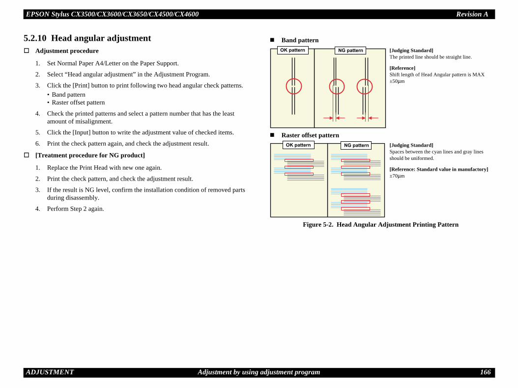
EPSON Stylus CX3500/CX3600/CX3650/CX4500/CX4600 Revision A
A 166
5.
gular Adjustment Printing Pattern
n
tern
[Judging Standard]The printed line should be straight line.
[Reference]Shift length of Head Angular pattern is MAX ±50µm
[Judging Standard]Spaces between the cyan lines and gray lines should be uniformed.
[Reference: Standard value in manufactory]±70µm
DJUSTMENT Adjustment by using adjustment program
2.10 Head angular adjustmentAdjustment procedure
1. Set Normal Paper A4/Letter on the Paper Support.
2. Select “Head angular adjustment” in the Adjustment Program.
3. Click the [Print] button to print following two head angular check patterns.• Band pattern• Raster offset pattern
4. Check the printed patterns and select a pattern number that has the least amount of misalignment.
5. Click the [Input] button to write the adjustment value of checked items.
6. Print the check pattern again, and check the adjustment result.
[Treatment procedure for NG product]
1. Replace the Print Head with new one again.
2. Print the check pattern, and check the adjustment result.
3. If the result is NG level, confirm the installation condition of removed parts during disassembly.
4. Perform Step 2 again.
Figure 5-2. Head An
OK pattern NG patter
OK pattern NG pat
Band pattern
Raster offset pattern

EPSON Stylus CX3500/CX3600/CX3650/CX4500/CX4600 Revision A
A 167
5.
on the Paper Support.
the Adjustment Program.
print the PW adjustment pattern.
and select a pattern number that has 5mm margins
write the adjustment value of checked items.
product]
th new one again.
check the adjustment result.
nfirm the installation condition of removed parts
adjustment Printing Pattern
[Judging Standard]Top / Bottom / Right / Left: 5mm
DJUSTMENT Adjustment by using adjustment program
2.11 Bi-D adjustmentAdjustment procedure
1. Set Normal Paper A4/Letter on the Paper Support.
2. Select “Bi-D adjustment” in the Adjustment Program.
3. Click the [Print] button to print the Bi-D adjustment pattern.
4. Check the printed patterns and select a pattern number that has the least amount of misalignment in each of the VSD dots.
5. Click the [Input] button to write the adjustment value of checked items.
6. Print the check pattern again, and check the adjustment result.
[Treatment procedure for NG product]
1. Replace the Print Head with new one again.
2. Print the check pattern, and check the adjustment result.
3. If the result is NG level, confirm the installation condition of removed parts during disassembly.
4. Perform Step 2 again.
Figure 5-3. Bi-D Adjustment Printing Pattern
5.2.12 PW adjustment Adjustment procedure
1. Set Photo Paper A4/Letter
2. Select “PW adjustment” in
3. Click the [Print] button to
4. Check the printed patternsfrom the paper edges.
5. Click the [Input] button to
[Treatment procedure for NG
1. Replace the PW Sensor wi
2. Print the check pattern, and
3. If the result is NG level, coduring disassembly.
4. Perform Step 2 again.
Figure 5-4. PW
OK pattern NG pattern [Judging Standard]The block patterns should align without gap and overlapping.
[Reference]GAP Bi-D for each Dot
• VSD1 BLACK, COLOR: 60µm• VSD3 BLACK, COLOR: 40µm

EPSON Stylus CX3500/CX3600/CX3650/CX4500/CX4600 Revision A
A 168
5.
5.
rn
t (A4)
Paper Support.
” in the Adjustment Program.
(A4 x 1), click the [Print] button to print Normal
lt in each pattern.
ormal Paper Print Pattern
DJUSTMENT Adjustment by using adjustment program
2.13 First dot position adjustmentAdjustment procedure
1. Set Photo Paper A4/Letter on the Paper Support.
2. Select “First dot position adjustment” in the Adjustment Program.
3. Click the [Print] button to print the First dot position adjustment pattern.
4. Check the printed patterns and select a pattern number that has 5mm margin from the paper edge.
5. Click the [Input] button to write the adjustment value of checked item.
[Treatment procedure for NG product]
1. Replace the repaired (replaced) part with new one.
2. Print the check pattern, and check the adjustment result.
3. If the result is NG level, confirm the installation condition of removed parts during disassembly.
4. Perform Step 2 again.
Figure 5-5. First dot position adjustment Printing Pattern
2.14 CR motor heat protection controlAdjustment procedure
1. Select “CR motor heat protection control” in the Adjustment Program.
2. Check each box of the replaced parts/units checklist and then click the [Perform] button.
3. A dialogue box will be displayed, and click the [OK] button in the box.
5.2.15 Print check patte
5.2.15.1 Normal Paper Prin Adjustment procedure
1. Set Plain Paper A4 on the
2. Select “Print check pattern
3. After selecting Plain PaperPaper Print Pattern.
4. Check the adjustment resu
Figure 5-6. N
-4
0
4
8
[Judging Standard]Standard: 5mm away from left edge.

EPSON Stylus CX3500/CX3600/CX3650/CX4500/CX4600 Revision A
A 169
5.2
DJUSTMENT Adjustment by using adjustment program
.15.2 Photo Quality Inkjet Paper Print (Letter)1. Set Plain Paper Letter on the Paper Support.
2. Select “Print check pattern” in the Adjustment Program.
3. After selecting Photo Quality Inkjet Paper (Letter x 1), click the [Print] button to print Photo Quality Inkjet Paper Print Pattern.
4. Check the adjustment result in each pattern.
Figure 5-7. Photo Quality Inkjet Paper Print Pattern

EPSON Stylus CX3500/CX3600/CX3650/CX4500/CX4600 Revision A
A 170
5.Fo
5.
the position shown by the figure. The thickness tween the front of the Paper Guide Front Unit and
ent position for thickness gauge
owered. If PG Lever is raised, lower it.
the thickness gauge by using the Timing Belt, and s gauge moves or not.
arriage Unit directly, it’s possible to damage urface by the friction with the thickness gauge.relationship between “Parallel Adjustment ration” and “Platen gap reaction”.
nship between Parallel Adjustment Lever (Left) Operation & Platen Gap
hickness gauge
PG up (narrower)
PG down (wider)
DJUSTMENT Adjustment Except Adjustment Program
3 Adjustment Except Adjustment Programllowing is adjustment except Adjustment Program.
3.1 PG adjustmentParts to be Removed and Replaced
Removal and Replacement of Carriage Unit
Removal and Replacement of Print Head
Adjustment procedure
1. Make sure that the printer is turned off.
2. Set the ink cartridges into the Carriage Unit
3. Prepare the thickness gauge. (The thickness should be 1.45mm.)
4. Loosen the screw (C.B.S 3x6) for securing the Parallel Adjustment Lever (Left).
Figure 5-8. Parallel Adjustment Lever (Left) Location
5. Release the Carriage Lock if the Carriage Unit is locked.
6. Set the thickness gauge at gauge should be placed bethe center ribs.
Figure 5-9. Placem
7. Confirm that PG Lever is l
8. Move the Carriage Unit oncheck whether the thicknes
Do not remove a screw completely. (two or three revolution) You need not to loosen the screw securing the Parallel
Adjustment Lever (Right).
C.B.S 3x6Parallel Adjustment Lever (Left)
If you push the Cthe Print Head s
Following is the Lever (Left) ope
Figure 5-10. Relatio
T

EPSON Stylus CX3500/CX3600/CX3650/CX4500/CX4600 Revision A
A 171
x6) for securing the Parallel Adjustment Lever
Adjustment Lever (Right) Location
the position shown by the figure. The thickness tween the front of the Paper Guide Front Unit and
ment position for thickness gauge
N
screw completely. (two or three revolution) loosen the screw for securing the Parallel er (Light).
C.B.S 3x6
Parallel Adjustment Lever (Right)
Thickness gauge
DJUSTMENT Adjustment Except Adjustment Program
9. Accede to following steps until you’ve completed the left side PG adjustment.
Figure 5-11. Left Side PG Adjustment
10. Tighten the screw for securing Parallel Adjustment Lever (Left) temporary.
11. Loosen the screw (C.B.S 3(Right).
Figure 5-12. Parallel
12. Set the thickness gauge at gauge should be placed bethe center ribs.
Figure 5-13. Place
START
Move the Carriage Unit by using the Timing Belt.
Thickness Gauge moves?
One notch up the Parallel Adjustment Lever (Left).
One notch down the Parallel Adjustment Lever (Left).
Move the Carriage Unit by using the Timing Belt.
Thickness Gauge moves?
Advance to Step 10.
Step 8
Yes
Yes
No
No
Note : “Down” means PG (Platen Gap) wide.
ote : “Up” means PG (Platen Gap) narrow.
Do not remove a You need not to
Adjustment Lev

EPSON Stylus CX3500/CX3600/CX3650/CX4500/CX4600 Revision A
A 172
until you’ve completed the right side PG
Right Side PG Adjustment
for Parallel Adjustment Lever (Right) temporary.
position shown by Figure 5-9 again.
y
l ).
One notch down the Parallel Adjustment Lever (Right).
Move the Carriage Unit by using the Timing Belt.
Thickness Gauge moves?
Advance to Step 15.
tep 13
Yes
Yes
No
Note : “Down” means PG (Platen Gap) wide.
narrow.
DJUSTMENT Adjustment Except Adjustment Program
13. Move the Carriage Unit on the thickness gauge by using the Timing Belt, and check whether the thickness gauge moves or not.
14. Accede to following steps adjustment.
Figure 5-15.
15. Tighten the screw securing
16. Set the thickness gauge at
If you push the Carriage Unit directly, it's possible to damage the Print Head surface by the friction with the thickness gauge.
Following is the relationship between “Parallel Adjustment Lever (Right) operation” and “Platen gap reaction”.
Figure 5-14. Relationship between Parallel Adjustment Lever (Right) Operation & Platen Gap
PG up (narrower)
PG down (wider)
START
Move the Carriage Unit busing the Timing Belt.
Thickness Gauge moves?
One notch up the ParalleAdjustment Lever (Right
S
No
Note : “Up” means PG (Platen Gap)

EPSON Stylus CX3500/CX3600/CX3650/CX4500/CX4600 Revision A
A 173
ositioning adjustmentlaced
d Unit
Unit
nd confirm whether or not PF Scale is positioned
the center of PF Sensor, adjustment is complete. If enter of sensor, adjust position of PF Scale using s shown in diagram below.
ale Sensor positioning adjustment
Right side
Scale
Spacer is not applied to Main Board Unit for service part. Place spacer between Shield
Board and Main Board. If PF Scale is off to the left,
remove the spacer. If PF Scale is off to the right,
add an additional spacer. (Total of 2 spacers)
DJUSTMENT Adjustment Except Adjustment Program
17. Accede to following steps to check left side PG again.
Figure 5-16. Right/Left Sides PG Checking
18. Tighten both screws completely.
5.3.2 PF Scale Sensor p Parts to be Removed and Rep
Replacement of Main Boar
Replacement of PF Roller
Adjustment procedure
1. Test fit Main Board Unit, ain the center of PF Sensor.
2. If PF Scale is positioned inscale is not positioned in cspacer (0.5mm thickness) a
Figure 5-17. PF Sc
START
Move the Carriage Unit by using the Timing Belt.
Thickness Gauge moves?
One notch up the Parallel Adjustment Lever (Left).
Move the Carriage Unit by using the Timing Belt.
Thickness Gauge moves?
Re-adjust from the beginning.
One notch down the Parallel Adjustment Lever (Left).
Advance to Step 18.
Yes
Yes
NoNote : “Up” means PG (Platen Gap) narrow.
Note : “Down” means PG (Platen Gap) wide.
No
Re-adjust from the beginning.
Left side
0.1 to1.0mm
Spacer
PF

C H A P T E R
AINTENANCE
M
EPSON Stylus CX3500/CX3600/CX3650/CX4500/CX4600 Revision A
M 175
6.Th
6.ThPriand
a clean dry cloth. In case dirt is serious or alien ith a cloth moistened with neutral detergent. In case ith a dry clean cloth.
cehite line, etc.) has occurred or the printer indicates is error is displayed as “Maintenance call error” in ns to clear the error.
henomenon has occurred, you need to perform the 1 by using the Print Head cleaning function. This e control panel operation, the printer driver utility
ce is performed by the control panel operation, nd-by state (the Power LED is lighting), and hold l panel for more than 3 seconds. Then, the printer e Power LED blinks during this sequence). orm the manual cleaning by the printer driver aning mode is selected. The following is the ad cleaning from the printer driver utility. ustment program, refer to Chapter 5 Adjustment.
0/CX3600/CX3650/CX4500/CX4600 has 3 cleaning, and even during printing, the ing mode is automatically selected and ing to various conditions. Therefore the ink nt for manual cleaning varies depending on
to Chapter 2).
AINTENANCE Overview
1 Overviewis section provides information to maintain the printer in its optimum condition.
1.1 Cleaningis printer has no mechanical components which require regular cleaning except the nt Head. Therefore, when returning the printer to the user, check the following parts perform appropriate cleaning if stain is noticeable.
Exterior partsUse a clean soft cloth moistened with water, and wipe off any dirt. If the exterior parts are stained by the ink, use a cloth moistened with neutral detergent to wipe it off.
Inside the printerUse a vacuum cleaner to remove any paper dust.
LD RollerWhen paper loading function does not operate because friction of the LD Roller is lowered by any paper dust, set the adhesive side up of the cleaning sheet (included in the media) to remove any paper dust. Repeat loading the cleaning sheet several times.
Document glassRemove dust or any paper withsubstance is stick, wipe it off wStain is remained, wipe again w
6.1.2 Service MaintenanIf any abnormal print (dot missing, wthe “Maintenance request error” (Ththe STM3), take the following actio
Print Head cleaningWhen dot missing or banding pPrint Head cleaning operation*function can be performed by thand the Adjustment program. In case that the cleaning sequenconfirm that the printer is in stadown the Ink SW on the controstarts the cleaning sequence (thIn case that you select and perfutility, the most appropriate cleprocess to perform the Print HeAs for the operation of the Adj
NOTE: *1: The Stylus CX350modes for manualappropriate cleanperformed accordconsumption amoueach mode (Refer
Never use chemical solvents, such as thinner, benzine, and
acetone to clean the exterior parts of the printer like the Housing. These chemicals may deform or deteriorate the components of the printer.
Be careful not to damage any components when you clean inside the printer.
Do not scratch the coated surface of the PF Roller Unit. Use soft brush to wipe off any dusts. Use a soft cloth moistened with alcohol to remove the ink stain.
Do not use cleaning sheet included in the media for normal usage. It may damage the coated surface of PF Roller Unit.If the adhesive surface of the cleaning sheet is set to the LD Roller shaft side and used to clean the LD Roller surface, it is no problem.

EPSON Stylus CX3500/CX3600/CX3650/CX4500/CX4600 Revision A
M 176
1.
2.
intenance call error)leaning operation as well as the printing operation. int Head cleaning operation, the ink is drained to unt of the waste ink is stored as the waste ink
he Main Board. Due to this, when the waste ink the absorbing capability of the Waste ink pads, the ted on Status monitor 3 as following figure. But ed by usage, therefore waste ink max counter is not
the present maximum value of the waste ink counter is condition. The range of maximum value is from 14700 nitial maximum value of non-used printer.)
enance error indication in STM3
k pads and clear the waste ink counter stored into r can be reset only from the Adjustment program e waste ink counter reset function by the control
er to Chapter 5 Adjustment. ste ink counter along with the firmware version, n and nozzle check pattern on the nozzle check nter is closed to its limit, recommend that the
h new one. This is because the “Maintenance eturning the repaired product to the customer.
AINTENANCE Overview
Select the “EPSON Status Monitor 3” in the printer driver utility, and make sure that the printer is in stand-by state by using the Status monitor 3. If the printer is in stand-by state, the following figure is indicated on the monitor.
Figure 6-1. Status monitor 3 indication
Select the “Head Cleaning” in the printer driver utility, and perform the Print Head cleaning. After performing the Print Head cleaning operation, print a nozzle check pattern by selecting the “Nozzle Check“. If you repeat the Print Head cleaning operation without selecting the “Nozzle Check”, CL1, the weakest cleaning, will be repeated.
Figure 6-2. Head cleaning function in the printer driver utility
Maintenance request error (MaInk is used for the Print Head cWhen the ink is used for the Prthe Waste ink pads and the amocounter into the EEPROM on tcounter has reached the limit ofMaintenance call error is indicawaste ink max counter is changnecessarily right. *1
Note *1: Unlike current model, changed by the printerto 36000. ( means i
Figure 6-3. Maint
In this case, replace to new Waste inthe EEPROM. The waste ink countebecause this printer dose not have thpanel SW. As for the procedure, refIn your repair activity, check the waMain Board checker program versiopattern printing. If the waste ink couWaste ink pads will be replaced witrequest error” will may occur after r

EPSON Stylus CX3500/CX3600/CX3650/CX4500/CX4600 Revision A
M 177
6.Thdurandresam
or the lubrication points.
re 6-4. Lubrication
re 6-5. Lubrication
<Lubrication Point>Scanner Carriage Shaft surface
<Lubrication Type>G-26
<Lubrication Amount>2mm x 4 points
<Remarks>Use a brush to apply it
<Lubrication Point>1. Paper Return Lever surface2. Hopper surface
<Lubrication Type>1. G-462. G-26
<Lubrication Amount>1. Adequate dose2. φ1 x 1mm
<Remarks>1. Use a flux dispenser to apply it2. Use a injector to apply it• Grease application must not
spread to other parts.
3mm
2mm
n center
Hopper
r Return Lever
AINTENANCE Overview
1.3 Lubricatione characteristics of the grease have great affects on the mechanical function and ability, especially does the characteristics about temperature environment. The type amount of the grease used to lubricate the printer parts are determined based on the
ults of the internal evaluations. Therefore, be sure to apply the specified type and ount of the grease to the specified part of the printer mechanism during servicing.
Refer to the following figures f
Figu
Figu
Never use oil or grease other than those specified in this manual.
Use of different types of oil or grease may damage the component or give bad influence on the printer function.
Never apply larger amount of grease than specified in this manual.
Table 6-1. Specified lubricantsType Name EPSON code Supplier
Grease G-26 1080614 EPSON
Grease G-46 1039172 EPSON
Grease G-71 1304682 EPSON
When using G-46, it is recommended to use a flux dispenser (1049533) together.
Scanner Carriage Shaft
3mm 3mm 3mm
2mm2mm2mm
Scanner Carriage Unit position o
1
2
Pape

EPSON Stylus CX3500/CX3600/CX3650/CX4500/CX4600 Revision A
M 178
re 6-7. Lubrication
re 6-8. Lubrication
<Lubrication Point>1. 2 position on holes of Carriage
(touch to Carriage Guide Shaft)2. Carriage Guide Shaft surface
<Lubrication Type>1. G-712. G-71
<Lubrication Amount>1. 150 ~ 210mg
(total on 2 positions)2. 120 ~ 160mg
(total on 2 positions)
<Remarks>1. Use a injector to apply it2. Use a injector to apply it• KEN Grease must not spread to
Timing Belt.
<Lubrication Point>Contact point between EJ Roller Unit and 3 hooks of Front Paper Guide Support
<Lubrication Type>G-46
<Lubrication Amount>Adequate dose
<Remarks>• Use a flux dispenser to apply it• G-46 must not spread to rubber
part of EJ Roller Unit.
2
.
.
Carriageoutsidesurface
CarriageGuideShaft
Right side
EJ Roller Unit
AINTENANCE Overview
Figure 6-6. Lubrication
Figu
Figu
<Lubrication Point>4 Ditches of Pully Driven Holder
<Lubrication Type>G-26
<Lubrication Amount>φ1 x 1mm x 4 points
<Remarks>• Use a injector to apply it• Wipe the unnecessary grease by
bemcoat.• Grease must not spread to Pully
Driven area.
21 1
N.G
O.K
KEN Grease applied limit line
Carriage hole
Carriage
Left side
CenterFront Paper
Guide Support

EPSON Stylus CX3500/CX3600/CX3650/CX4500/CX4600 Revision A
M 179
e 6-11. Lubrication
e 6-12. Lubrication
<Lubrication Point>1. Edge line of Link Lever (Left)2. Around 2 dowels of Link Lever
Holder (Left)
<Lubrication Type>1. G-262. G-26
<Lubrication Amount>1. φ1 x 1mm2. φ1 x 2 points
<Remarks>Use a injector to apply it
<Lubrication Point>1. Edge line of Link Lever (Right)2. Around 2 dowels of Main
Frame (Right)
<Lubrication Type>1. G-262. G-26
<Lubrication Amount>1. φ1 x 1mm2. φ1 x 2 points
<Remarks>Use a injector to apply it
2
ft)
2
AINTENANCE Overview
Figure 6-9. Lubrication
Figure 6-10. Lubrication
Figur
Figur
<Lubrication Point>Points on the left side of Paper Guide Front Unit as shown in the figure
<Lubrication Type>G-26
<Lubrication Amount>φ1 x 1mm x 2 points
<Remarks>Use a injector to apply it
<Lubrication Point>From the left edge of the Front Frame (left line mark) to the right edge of that (right line mark)
<Lubrication Type>G-71
<Lubrication Amount>200mg
<Remarks>Use a injector to apply it
Left side
Paper Guide Front Unit
Left line mark Right line markFront Frame
1
2
Link Lever Holder (Le
Link Lever (Left)
1
2

EPSON Stylus CX3500/CX3600/CX3650/CX4500/CX4600 Revision A
M 180
AINTENANCE OverviewFigure 6-13. Lubrication
Figure 6-14. Lubrication
<Lubrication Point>1. Contact point between PF
Grounding Spring and PF Roller Unit
2. Contact point between Paper Guide Rear and PF Roller Unit
<Lubrication Type>1. G-262. G-26
<Lubrication Amount>1. φ1 x φ of PF Roller Unit2. φ1 x φ of PF Roller Unit
<Remarks>Use a injector to apply it
<Lubrication Point>Contact point between Bush 10 (Right) and PF Roller Unit
<Lubrication Type>G-26
<Lubrication Amount>φ1 x φ of PF Roller Unit
<Remarks>Use a injector to apply it
12
PF Grounding Spring
Paper Guide Rear
PF Roller Unit
Bush 10 (Right)
Right side of PF Roller UnitPF Roller Unit

C H A P T E R
APPENDIX

EPSON Stylus CX3500/CX3600/CX3650/CX4500/CX4600 Revision A
A 182
7.
7.Th
Th
nector summary for the C571 Main board, C577 n alignment.
C
ummary for C571/C577 Main Boardunction Table to refer to
e Power Supply Board Table 7-2 (p.182)
e USB interface “1.3.1 USB Interface” (p.22)
e PE Sensor Table 7-3 (p.183)
e PG Sensor Table 7-4 (p.183)
e Print HeadTable 7-5 (p.183), Table 7-6 (p.183), Table 7-7 (p.184)
e CR Motor Table 7-8 (p.184)
e PF Motor Table 7-9 (p.184)
e Scanner Motor Table 7-10 (p.184)
e Scanner Carriage FFC Table 7-11 (p.184)
e Panel Board Table 7-12 (p.185)
e Scanner HP Sensor Table 7-13 (p.185)
e Memory Card Table 7-14 (p.185), Table 7-15 (p.186)
N1 - Power Supply Board
I/O Function
— +42V
— Ground
I Power supply control
PPENDIX Connector Summary
1 Connector Summary
1.1 Major Component Unite major component units of this printer are as follows.
Main Board (C571 Main, C577Main)
Power Supply Board (C571 PSB/PSE)
Panel Board (C571 PNL)
e figure below shows how to connect these components.
Figure 7-1. Connection of the major components
See the following tables for the conMain board and each connector’s pi
P1
PF Encoder Sensor
C571 Main/C577 Main
CN3
CN2571 PSB/PSE
CN2
AC power
Printer Mechanism
USB I/FCN2
CN13
CN11
CN10
Scanner HP Sensor
Scanner Carriage FFC
Scanner MotorScanner Mechanism
PE Sensor
CN4
PG Sensor
CN5,CN6,CN7
Print Head
CN8
CR Motor
CN12
CN9
PF Motor
C571 PNL
CN14, CN15
Memory Card
Only for C571 Main
Table 7-1. Connector SConnector F
CN1 For connection with th
CN2 For connection with th
CN3 For connection with th
CN4 For connection with th
CN5 to CN7 For connection with th
CN8 For connection with th
CN9 For connection with th
CN10 For connection with th
CN11 For connection with th
CN12 For connection with th
CN13 For connection with th
CN14 to CN15 For connection with th
Table 7-2. C
Pin Signal Name
1 +42V
2 GND
3 PSC

EPSON Stylus CX3500/CX3600/CX3650/CX4500/CX4600 Revision A
A 183
-6. CN6 - Print Head
I/O Function
— Ground
O Head drive pulse (trapezoid waveform)
— Ground
O Head drive pulse (trapezoid waveform)
O +42V power supply for nozzle selector
— Ground
— Serial clock
— Ground
O Charge signal for the trapezoidal wave-form
— +3.3V
O Print data output for magenta nozzles
— Ground
O Print data output for cyan nozzles
PPENDIX Connector Summary
Table 7-3. CN3 - PE Sensor
Pin Signal Name I/O Function
1 PE I PE Sensor signal
2 GND — Ground
3 PEV — Power supply for PE Sensor
Table 7-4. CN4 - PG Sensor
Pin Signal Name I/O Function
1 PG I PG Sensor signal
2 GND — Ground
Table 7-5. CN5 - Print Head
Pin Signal Name I/O Function
1 XHOT/THM I Head temperature signal
2 SI2_Ye O Print data output for yellow nozzles
3 VDD2 — +3.3V
4 SI1_Bk O Print data output for black nozzles
5 GND — Ground
6 NCHG O All nozzle fire selection pulse
7 GND — Ground
8 LAT O Head data latch pulse output
9 NC — Not connected
10 GND2 — Ground
11 COM O Head drive pulse (trapezoid waveform)
12 GND2 — Ground
13 COM O Head drive pulse (trapezoid waveform)
Table 7
Pin Signal Name
1 GND2
2 COM
3 GND2
4 COM
5 VHV
6 GND
7 SCK
8 GND
9 CH
10 VDD
11 SI3_Ma
12 GND
13 SI4_Cy

EPSON Stylus CX3500/CX3600/CX3650/CX4500/CX4600 Revision A
A 184
. CN10 - Scanner Motor
I/O Function
O Phase drive signal (-A)
O Phase drive signal (B)
O Phase drive signal (A)
O Phase drive signal (-B)
CN11 - Scanner Carriage
I/O Function
O Output signal
— Power supply for filtered 5V_SW (analog)
— Ground
O Clock
O Reset
O Shift pulse
— Ground
— Power supply for 5V_SW (digital)
O LED cathode (Red)
O LED cathode (Green)
O LED cathode (Blue)
— Power supply for LED
PPENDIX Connector Summary
Table 7-7. CN7 - Print Head
Pin Signal Name I/O Function
1 COI I Cartridge detect signal
2 CSDA I/O CSIC transmit and receive data
3 CRST O Reset signal for address counter of CSIC
4 GND2 — Ground
5 CVDD O Power supply for CSIC
6 CSCK I/O Clock signal for CSIC read/write
7 NC — Not connected
8 GND — Ground
9 ENCB I Encoder feed back signal ch.B
10 EVDD O Power for CR Encoder
11 ENCA I Encoder feed back signal ch.A
12 NC — Not connected
13 PW I PW Sensor signal
14 GND — Ground
15 LEDON — Power supply for PW sensor
Table 7-8. CN8 - CR Motor
Pin Signal Name I/O Function
1 CR-A O CR Motor drive signal (A)
2 CR-B O CR Motor drive signal (B)
Table 7-9. CN9 - PF Motor
Pin Signal Name I/O Function
1 PF-A O PF Motor drive signal (A)
2 PF-B O PF Motor drive signal (B)
Table 7-10
Pin Signal Name
1 B
2 AX
3 A
4 BX
Table 7-11.
Pin Signal Name
1 OS
2 VAD
3 GND
4 M
5 RS
6 TR
7 GND
8 VDD
9 LED R
10 LED G
11 LED B
12 LED CA

EPSON Stylus CX3500/CX3600/CX3650/CX4500/CX4600 Revision A
A 185
Card enable signal
Address bus for CF slot (10)
Output enable signal
Address bus for CF slot (9)
Address bus for CF slot (8)
Address bus for CF slot (7)
— Power supply for CompactFlash
Address bus for CF slot (6)
Address bus for CF slot (5)
Address bus for CF slot (4)
Address bus for CF slot (3)
Address bus for CF slot (2)
Address bus for CF slot (1)
Address bus for CF slot (0)
Data bus for CF slot (0)
Data bus for CF slot (1)
Data bus for CF slot (2)
Write protect - I/O port 16 bit
Card detect signal
Card detect signal
Data bus for CF slot (11)
Data bus for CF slot (12)
Data bus for CF slot (13)
Data bus for CF slot (14)
Data bus for CF slot (15)
. CN14 - Memory Card
I/O Function
PPENDIX Connector Summary
Table 7-12. CN12 - Panel Board
Pin Signal Name I/O Function
1 SDI I Switch data serial data input
2 SENB O LED lamp enable signal
3 SALT O Switch data load signal and LED data latch signal
4 CLK O Shift clock for serial data I/O
5 PSW I/O TBD
6 SDO O Serial data output for LED control
7 +3.3V — +3.3V
8 GND — Ground
01 GND — Ground
02 GND — Ground
Table 7-13. CN13 - Scanner HP Sensor
Pin Signal Name I/O Function
1 SCN_HP I Scanner HP Sensor signal
2 GND — Ground
3 PEV — Power supply for Scanner HP Sensor
Table 7-14. CN14 - Memory Card
Pin Signal Name I/O Function
1 GND — Ground
2 CD3 Data bus for CF slot (3)
3 CD4 Data bus for CF slot (4)
4 CD5 Data bus for CF slot (5)
5 CD6 Data bus for CF slot (6)
6 CD7 Data bus for CF slot (7)
7 /CE1
8 CA10
9 /OE
10 CA9
11 CA8
12 CA7
13 VCC
14 CA6
15 CA5
16 CA4
17 CA3
18 CA2
19 CA1
20 CA0
21 CD0
22 CD1
23 CD2
24 WP/IOIS16B
25 /CD2
26 /CD1
27 CD11
28 CD12
29 CD13
30 CD14
31 CD15
Table 7-14
Pin Signal Name

EPSON Stylus CX3500/CX3600/CX3650/CX4500/CX4600 Revision A
A 186
Write enable signal
Write protect signal
SSFDC data (Bit 0)
SSFDC data (Bit 1)
SSFDC data (Bit 2)
SSFDC data (Bit 3)
— Ground
— Not connected
— Power supply for SmartMedia
SSFDC data (Bit 4)
SSFDC data (Bit 5)
SSFDC data (Bit 6)
SSFDC data (Bit 7)
Low Voltage Detect
— Ground
Ready
Output enable signal
Chip enable signal
— Power supply for SmartMedia
— Ground
Serial protocol bus state signal
— Power supply for MemoryStick
Serial protocol data signal
— Not connected
Serial protocol data signal
. CN15 - Memory Card
I/O Function
PPENDIX Connector Summary
32 /CE2 Card enable signal
33 NC/VS1 Voltage sensing 1
34 /IORD I/O read
35 /IOWR I/O write
36 /WE Write enable signal
37 RDY Ready
38 VCC — Power supply for CompactFlash
39 /CSEL — Not connected
40 RPU/VS2 Voltage sensing 2
41 RESET Reset
42 /WAIT Bus cycle extension
43 INPACK Input port response
44 /REG Register select
45 BVD2/SPKA Battery voltage detect/audio digital waveform
46 BVD1/STSCHG Battery voltage detect/card status change
47 CD8 Data bus for CF slot (8)
48 CD9 Data bus for CF slot (9)
49 CD10 Data bus for CF slot (10)
50 GND — Ground
Table 7-15. CN15 - Memory Card
Pin Signal Name I/O Function
1 GND — Ground
2 FCLE Command latch enable signal
3 FALE Address latch enable signal
Table 7-14. CN14 - Memory Card
Pin Signal Name I/O Function
4 FWEB
5 FWPB
6 FD0
7 FD1
8 FD2
9 FD3
10 GND
11 CD1
12 VCC
13 FD4
14 FD5
15 FD6
16 FD7
17 FLVD
18 GND
19 FRDY
20 FOEB
21 FCEB
22 VCC
M1 GND
M2 BS
M3 VCC
M4 SDIO
M5 Reserve
M6 INS
Table 7-15
Pin Signal Name

EPSON Stylus CX3500/CX3600/CX3650/CX4500/CX4600 Revision A
A 187
Card detect signal
— Ground
Write protect seal condition
— Ground
Card detect signal
Card Detect /Data Line (Bit 3)
Command/Response
— Ground
— Power supply for SD Memory Card
Clock
— Ground
Data Line (Bit 0)
Data Line (Bit 1)
Data Line (Bit 2)
. CN15 - Memory Card
I/O Function
PPENDIX Connector Summary
M7 Reserve — Not connected
M8 SCLK Stick inserted/removed detect terminal
M9 VCC — Power supply for MemoryStick
M10 GND — Ground
X1 GND — Ground
X2 XD_RDY Ready
X3 XD_OEB Output enable signal
X4 XD_CEB Chip enable signal
X5 XD_CLE Command latch enable signal
X6 XD_ALE Address latch enable signal
X7 XD_WEB Write enable signal
X8 XD_WPB Write protect signal
X9 GND — Ground
X10 XD_D0 XD data (Bit 0)
X11 XD_D1 XD data (Bit 1(
X12 XD_D2 XD data (Bit 2)
X13 XD_D3 XD data (Bit 3)
X14 XD_D4 XD data (Bit 4)
X15 XD_D5 XD data (Bit 5)
X16 XD_D6 XD data (Bit 6)
X17 XD_D7 XD data (Bit 7)
X18 XD_VCC — Power supply for xD-Picture Card
S1 WP TBD
S2 SW_GND — Ground
S3 DETECT TBD
Table 7-15. CN15 - Memory Card
Pin Signal Name I/O Function
S4 CD
S5 GND
S6 WP1
S7 GND
S8 XD_CD1
D1 CD/DAT3
D2 CMD
D3 GND
D4 VDD
D5 CLK
D6 GND
D7 DAT0
D8 DAT1
D9 DAT2
Table 7-15
Pin Signal Name

EPSON Stylus CX3500/CX3600/CX3650/CX4500/CX4600 Revision A
A 188
7.
PPENDIX Component Layout
2 Component Layout
Figure 7-2. C571 Main board component layout (1)
Figure 7-3. C571 Main board component layout (2)

EPSON Stylus CX3500/CX3600/CX3650/CX4500/CX4600 Revision A
A 189
PPENDIX Component LayoutFigure 7-4. C577 Main board component layout (1)
Figure 7-5. C577 Main board component layout (2)
EPSON Stylus CX3500/CX3600/CX3650/CX4500/CX4600 Revision A
A 190
PPENDIX Component LayoutFigure 7-6. C571 PSB board component layout
Figure 7-7. C571 PSE board component layout

EPSON Stylus CX3500/CX3600/CX3650/CX4500/CX4600 Revision A
A 191
PPENDIX Component LayoutFigure 7-8. C571 Panel board component layout

EPSON Stylus CX3500/CX3600/CX3650/CX4500/CX4600 Revision A
A 192
7.Fo
am 1
1 0 50
5 4 5
1 0 7
E 0 1
PPENDIX Exploded Diagram
3 Exploded Diagramllowing pages show exploded diagram.
Figure 7-9. Stylus CX3500/CX3600/CX3650/CX4500/CX4600 Exploded Diagr
1 05 4 5
1 0 6
1 0 7
1 0 1
1 0 24 5 1
1 1 3
1 1 11 1 1
1 1 1
1 1 1
1 2 0
1 1 1
1 0 9
1 1 0
1 1 2
1 0 8
1 0 3
1 0 4
1 1 1
4 5 0
1 1 6
1 1 81 1 7
1 1 5
1 1 9
1 1 4
E P S O N S T Y L U S C X4 6 0 0 / C X 4 5 0 0 R e v . 0 1 C A S

EPSON Stylus CX3500/CX3600/CX3650/CX4500/CX4600 Revision A
A 193
ram 2
3 0 0
C 0 1
PPENDIX Exploded Diagram
Figure 7-10. Stylus CX3500/CX3600/CX3650/CX4500/CX4600 Exploded Diag
2 0 0
E P S O N S T Y L U S C X4 6 0 0 / C X 4 5 0 0 R e v . 0 1 E L E

EPSON Stylus CX3500/CX3600/CX3650/CX4500/CX4600 Revision A
A 194
ram 3
8 0 9
8 0 5
8 0 7
8 0 6
C H 0 1
PPENDIX Exploded Diagram
Figure 7-11. Stylus CX3500/CX3600/CX3650/CX4500/CX4600 Exploded Diag
8 0 0
8 0 4
8 0 3
8 0 1
8 0 1
8 1 0
8 0 2
x x x
E P S O N S T Y L U S C X4 6 0 0 / C X 4 5 0 0 R e v . 0 1 M E

EPSON Stylus CX3500/CX3600/CX3650/CX4500/CX4600 Revision A
A 195
ram 4
5 1 0
5 2 3
5 2 8
5 3 0
5 2 9
5 1 6
5 1 9
H 0 2
5 5 5
PPENDIX Exploded Diagram
Figure 7-12. Stylus CX3500/CX3600/CX3650/CX4500/CX4600 Exploded Diag
5 0 0
5 2 0
5 0 8
5 0 35 3 75 1 2
5 1 3
5 0 2
5 0 4
5 0 1
5 4 4
5 4 3
5 1 5
5 3 3
5 3 1
5 3 2
5 3 4
5 3 9
5 2 1
5 5 4
5 1 1
5 3 5
E P S O N S T Y L U S C X4 6 0 0 / C X 4 5 0 0 R e v . 0 1 M E C
5 1 8
5 1 7

EPSON Stylus CX3500/CX3600/CX3650/CX4500/CX4600 Revision A
A 196
ram 5
1
4 7
5 4 8
5 4 94 7
5 4 9
5 4 8
5 4 6
5 4 6
5 4 2
5 3 8
5 3 8
5 4 1
5 0 6
C H 0 3
PPENDIX Exploded Diagram
Figure 7-13. Stylus CX3500/CX3600/CX3650/CX4500/CX4600 Exploded Diag
5 2 4
5 2 6
5 2 5
5 1 45 0 5
5 2 7
5 0 7
5 3 6
5 2 2
5 5 3
5 5 0
5 5
5 5 2
5
5
E P S O N S T Y L U S C X4 6 0 0 / C X 4 5 0 0 R e v . 0 1 M E

EPSON Stylus CX3500/CX3600/CX3650/CX4500/CX4600 Revision A
A 197
7.
POROUS PAD,INK EJECT,2
POROUS PAD,INK EJECT,3
POROUS PAD,INK EJECT,4
POROUS PAD,INK EJECT,5
POROUS PAD,INK EJECT,6
POROUS PAD,INK EJECT,7
POROUS PAD,INK EJECT,8
SCANNER UNIT
SPRING,CIS
MOTOR ASSY.,SC
CIS
FFC,CIS
COVER,DOCUMENT ASSY.
MAT,COVER,DOCUMENT
HINGE,ASSY.
CR,MAIN
HINGE,L
MAIN BOARD ASSY.;C
POWER SUPPLY UNIT;100V;B
HARNESS
TER MECHANISM(ASP)MAK10-100
FRAME,FRONT
COVER,CABLE,HEAD
COVER,CARTRIDGE
FRAME,HOLDER,FFC
00/CX3600/CX3650/CX4500/CX4600Parts Name
PPENDIX Parts List
4 Parts List
Table 7-16. Stylus CX3500/CX3600/CX3650/CX4500/CX4600Code Parts Name
100 COVER,ASF
101 COVER,REAR;ECG
102 COVER,USB;ECG
103 HOUSING,CARD SLOT;ECG
104 COVER,CARD SLOT;EFS
105 PAPER SUPPORT ASSY.
106 HOUSING,UPPER ASSY.
107 LOCK,SCANNER;ECG
108 STACKER ASSY.
110 COMPRESSION SPRING,5.1
111 FOOT
112 LOCK,STACKER
113 HOUSING,LOWER;ECG
114 PANEL UNIT
116 BUTTON,COPY;EBM3
117 BUTTON,POWER;EBM3
118 BUTTON,S;EBM3
119 SHEET,PANEL;B
120 SPRING,COVER,CARD SLOT
450 BOARD ASSY.,PANEL
506 POROUS PAD,CAP,LOWER
540 POROUS PAD,JOINT,LOWER
546 POROUS PAD,INK EJECT,1
547
548
549
550
551
552
553
800
801
802
803
804
806
807
809
810
811
200
300
451
500 PRIN
501
502
503
504
Table 7-16. Stylus CX35Code

EPSON Stylus CX3500/CX3600/CX3650/CX4500/CX4600 Revision A
A 198
CABLE,HEAD
BOARD ASSY.,ENCORDER
BOARD ASSY.,DETECTOR,PW
MOTOR ASSY.,CR
DETECTOR ASSY.,PG
PRINT HEAD
CLAMP,TUBE
LEVER,PG
TUBE,INK EJECT
JOINT,INK EJECT
MOUNTING PLATE,LEVER,PG
TORSION SPRING,19.01
.B.P-TITE SCREW,3X10,F/ZN-3C
COMPRESSION SPRING,2.51
EXTENSION SPRING,0.143
TORSION SPRING,6.45
00/CX3600/CX3650/CX4500/CX4600Parts Name
PPENDIX Parts List
505 SCALE,PF
507 POROUS PAD,TUBE,UPPER
508 GUIDE,FFC
510 ASF UNIT
511 C.B.P-TITE SCREW,3X6,F/ZN-3C
512 CONNECTER,CSIC
513 BOARD ASSY.,CSIC
514 GROUNDING SPRING,PF
515 FRAME,GUIDE,CR
516 LEVER,PARALLEL ADJUSTMENT,RIGHT
517 LEVER,PARALLEL ADJUSTMENT,LEFT
518 TORSION SPRING,SHAFT,CR,GUIDE
519 PRESSING SPRING,SHAFT,CR,GUIDE
520 SCALE,CR
521 EXTENSION SPRING,3.289
522 PAPER GUIDE,FRONT,SUPPORT
523 INK SYSTEM ASSY.
524 MOTOR ASSY.,PF
525 ROLLER,PF ASSY.
526 PAPER GUIDE,UPPER ASSY.
527 PAPER GUIDE,FRONT ASSY.
528 HOLDER,SHAFT ASSY.
529 TORSION SPRING,0.22
530 BOARD ASSY.,DETECTOR
531 CR ASSY.
Table 7-16. Stylus CX3500/CX3600/CX3650/CX4500/CX4600Code Parts Name
532
533
534
535
536
537
538
539
541
542
543
544
545 C
554
555
556
Table 7-16. Stylus CX35Code

EPSON Stylus CX3500/CX3600/CX3650/CX4500/CX4600 Revision A
A 199
7.Th
PPENDIX Electrical Circuits
5 Electrical Circuitse electric circuit diagrams below are shown at the following pages:
C571 Main control circuit board
C577 Main control circuit board
C571 PSB/PSE power supply circuit board
C571 Panel circuit board