EPM-PS1a Reference Manual
22
Reference Manual DOC. REV. 4/29/2009 EPM-PS1 PC/104-Plus Power Supply Module
Transcript of EPM-PS1a Reference Manual

Reference Manual DOC. REV. 4/29/2009
EPM-PS1 PC/104-Plus Power Supply Module
EPM-PS1 Reference Manual ii
WWW.VERSALOGIC.COM
12100 SW Tualatin Road Tualatin, OR 97062-7341
(503) 747-2261 Fax (971) 224-4708
Contents Copyright © 2013 All Rights Reserved
Notice: Although every effort has been made to ensure this document is error-free, VersaLogic makes no representations or warranties with respect to this product and specifically disclaims any implied warranties of merchantability or fitness for any particular purpose.
VersaLogic reserves the right to revise this product and associated documentation at any time without obligation to notify anyone of such changes.
PC/104 and the PC/104 logo are trademarks of the PC/104 Consortium.
MEPMPS1
EPM-PS1 Reference Manual iii
Product Release Notes Rev 3 Release Charlie release EPM-PS1a model only–no battery backup function.
Rev 2 Release Beta release.
Rev 1 Release Pre-production only. No customer shipments.
EPM-PS1 Reference Manual iv
Contents
Introduction ..................................................................................................................... 1
Features............................................................................................................................... 1 Technical Specifications ..................................................................................................... 2 Block Diagram.................................................................................................................... 3 RoHS-Compliance .............................................................................................................. 4
About RoHS........................................................................................................... 4 Warnings............................................................................................................................. 4
Electrostatic Discharge .......................................................................................... 4 Transient Voltage Suppression (TVS) Devices ..................................................... 5
Technical Support ............................................................................................................... 6 Repair Service........................................................................................................ 6
Physical Description.......................................................................................................7 Dimensions and Mounting.................................................................................................. 7
Hardware Assembly............................................................................................... 8 Stack Arrangement Example ................................................................................. 8
External Connectors............................................................................................................ 9 EPM-PS1 Connectors ............................................................................................ 9 EPM-PS1 Connector Functions and Interface Cables ......................................... 11
Jumper Block .................................................................................................................... 12 Jumpers As-Shipped Configuration..................................................................... 12
Operation ....................................................................................................................... 13 Main Power Input ............................................................................................................. 13 Power Out ......................................................................................................................... 13
J5 Connector Power Out ...................................................................................... 13 ISA and PCI Connector Power Out ..................................................................... 13
Power Supply Control....................................................................................................... 16 Efficiency and Derating .................................................................................................... 16
Appendix A – References.............................................................................................18

EPM-PS1 Reference Manual 1
Introduction
Features The EPM-PS1 is a DC switching power supply designed for high reliability in a wide variety of applications. The rugged design is conservatively rated to provide continuous 50 watt power output. When designing stacking PC/104-Plus compatible systems, OEMs and system integrators are able to develop entire systems using VersaLogic CPUs, I/O expansion modules and power supplies. Its features include:
PC/104-Plus compliant footprint. Transient voltage suppression
provides enhanced ESD protection. Protected against output over-
current, input over-current, and input polarity reversal.
Engineered to minimize heat generation with 91% peak efficiency.
Designed to provide -40° to +85°C operation for reliable use in harsh environments.
Full compliance with EU Directive 2002/95/EC (RoHS) for devices used in Europe.
Power is supplied into the PC/104-Plus (PCI) and PC/104 (ISA) buses or can be accessed from the screw clamp terminal blocks.
Each voltage output can be enabled or disabled with an external input signal.
All EPM-PS1 boards are subjected to functional testing and are backed by a limited two-year warranty. Careful parts sourcing and US-based technical support ensure the highest possible quality, reliability, service and product longevity for this exceptional PC/104-Plus module.
1

Introduction
EPM-PS1 Reference Manual 2
Technical Specifications Board Size:
3.55" x 3.775" (90 mm x 96 mm), PC/104 compliant
Storage Temperature: -40° C to +85° C
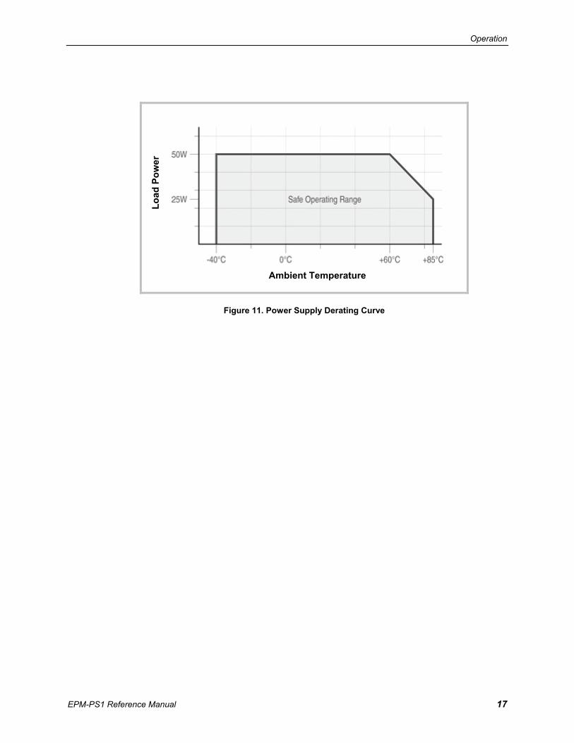
Operating Temperature: -40° C to +60° C at 50W, derated to 25W at +85°C (See Figure 11. Power Supply Derating Curve on page 17.)
Input Voltage Range: +9V to +40V DC
+5V Output: 50W (10A) max. continuous from -40° C to +60° C, derated to 25W (5A) at +85° C (See Figure 11. Power Supply Derating Curve on page 17.)
±12V Outputs: 1.8W (150 mA) each max. continuous from -40° C to +85° C
Output Regulation: 1% – all outputs
Output Voltage Ripple: 5V output : 30 mV pk-pk at 50% load ±12V output: 30 mv pk-pk at 50% load
Switching Frequency: 5V output: 200 KHz fixed ± 12V output: 1.2 MHz fixed
Bus Compatibility: PC/104 (ISA) PC/104-Plus (PCI)
Humidity: Less than 95%, noncondensing
ESD Protection: Transient voltage suppression and overload protection
Input Protection: Transient voltage suppression and fuse
Output Protection: Current limiting and transient voltage suppression
Weight: 0.239 lbs (0.108 kg)
Specifications are subject to change without notice.

Introduction
EPM-PS1 Reference Manual 3
Block Diagram
Figure 1. EPM-PS1 Block Diagram
Orange = Input Power. Red = 5V Output Power. Blue = ±12V Power Output. Green = Battery backup from battery card.
* Battery backup feature is not implemented on the EPM-PS1a model.
5 Volt 10 Amp HV Buck Regulator
± 12 Volt 100 MA Buck-Boost Regulator
Battery Backup Mezzanine Connector*
PC/104+ (PCI) Pass-through Connector
Power Connector
Input Power Conditioner
PC/104 (ISA) Pass-through Connector
Input Power
Connector

Introduction
EPM-PS1 Reference Manual 4
RoHS-Compliance The EPM-PS1 is RoHS-compliant.
ABOUT ROHS In 2003, the European Union issued Directive 2002/95/EC regarding the Restriction of the use of certain Hazardous Substances (RoHS) in electrical and electronic equipment.
The RoHS directive requires producers of electrical and electronic equipment to reduce to acceptable levels the presence of six environmentally sensitive substances: lead, mercury, cadmium, hexavalent chromium, and the presence of polybrominated biphenyls (PBB) and polybrominated diphenyl ethers (PBDE) flame retardants, in certain electrical and electronic products sold in the European Union (EU) beginning July 1, 2006.
VersaLogic Corporation is committed to supporting customers with high-quality products and services meeting the European Union’s RoHS directive.
Warnings ELECTROSTATIC DISCHARGE Electrostatic discharge (ESD) can damage board components. The circuit board must only be handled at an ESD workstation. If an approved station is not available, some measure of protection can be provided by wearing a grounded antistatic wrist strap. Keep all plastic away from the board, and do not slide the board over any surface.
After removing the board from its protective wrapper, place the board on a grounded, static-free surface, component side up. Use an antistatic foam pad if available.
The board should also be protected inside a closed metallic anti-static envelope during shipment or storage.
Introduction
EPM-PS1 Reference Manual 5
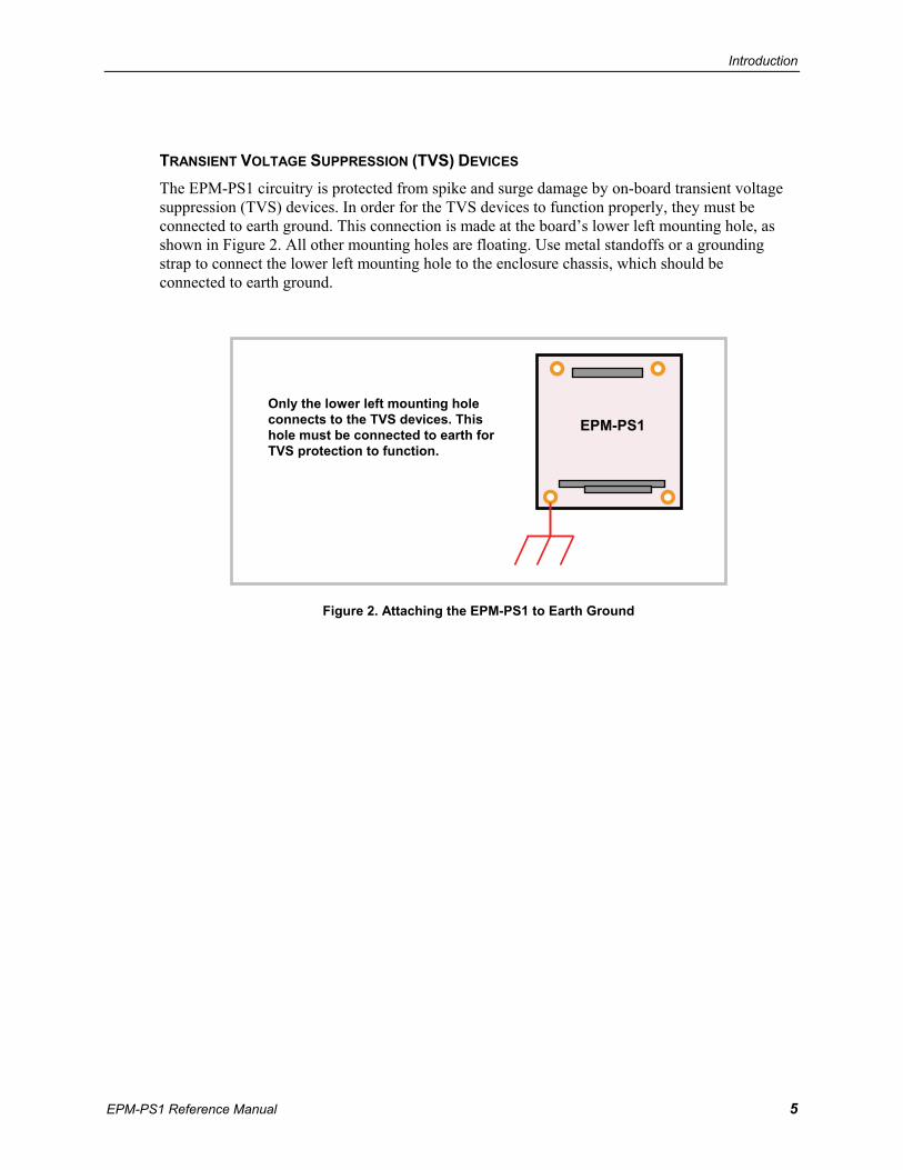
TRANSIENT VOLTAGE SUPPRESSION (TVS) DEVICES The EPM-PS1 circuitry is protected from spike and surge damage by on-board transient voltage suppression (TVS) devices. In order for the TVS devices to function properly, they must be connected to earth ground. This connection is made at the board’s lower left mounting hole, as shown in Figure 2. All other mounting holes are floating. Use metal standoffs or a grounding strap to connect the lower left mounting hole to the enclosure chassis, which should be connected to earth ground.
Figure 2. Attaching the EPM-PS1 to Earth Ground
Only the lower left mounting hole connects to the TVS devices. This hole must be connected to earth for TVS protection to function.
EPM-PS1

Introduction
EPM-PS1 Reference Manual 6
Technical Support If you are unable to solve a problem with this manual please, contact VersaLogic technical support at (541) 485-8575. VersaLogic technical support engineers are also available via e-mail at [email protected].
REPAIR SERVICE If your product requires service, you must obtain a Returned Material Authorization (RMA) number by calling (541) 485-8575.
Please provide the following information:
Your name, the name of your company and your phone number
The name of a technician or engineer that can be contact if any questions arise.
Quantity of items being returned
The model and serial number (barcode) of each item
A detailed description of the problem
Steps you have taken to resolve or recreate the problem
The return shipping address
Warranty Repair All parts and labor charges are covered, including return shipping charges for UPS Ground delivery to United States addresses.
Non-warranty Repair All non-warranty repairs are subject to diagnosis and labor charges, parts charges and return shipping fees. Please specify the shipping method you prefer and provide a purchase order number for invoicing the repair.
Note Please mark the RMA number clearly on the outside of the box before returning. Failure to do so can delay the processing of your return.
EPM-PS1 Reference Manual 7
Physical Description
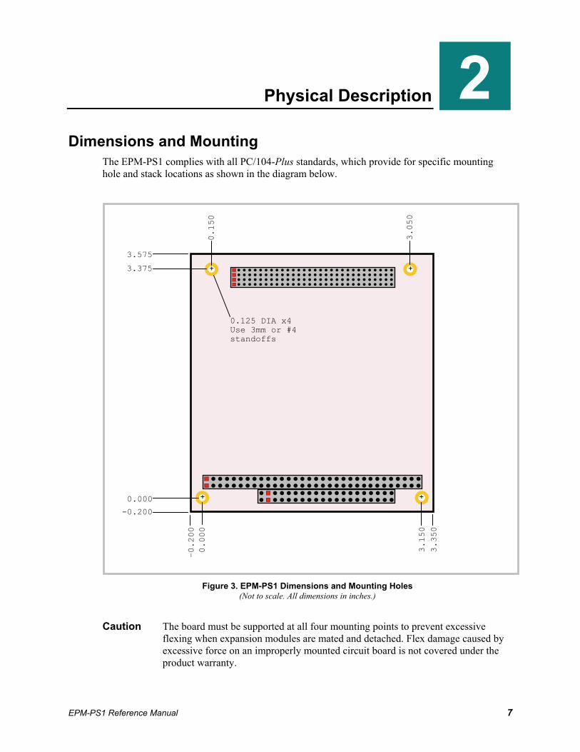
Dimensions and Mounting The EPM-PS1 complies with all PC/104-Plus standards, which provide for specific mounting hole and stack locations as shown in the diagram below.
Figure 3. EPM-PS1 Dimensions and Mounting Holes
(Not to scale. All dimensions in inches.)
Caution The board must be supported at all four mounting points to prevent excessive flexing when expansion modules are mated and detached. Flex damage caused by excessive force on an improperly mounted circuit board is not covered under the product warranty.
2–0.200
0.000
3.150
3.350
0.150
0.000
-0.200
3.575
3.375
3.050
0.125 DIA x4 Use 3mm or #4 standoffs
+
+
+
+

Physical Description
EPM-PS1 Reference Manual 8
HARDWARE ASSEMBLY The EPM-PS1 uses PC/104 and PC/104-Plus connectors so that expansion modules can be added to the top of the stack. PC/104 (ISA) modules must not be positioned between the EPM-PS1 and any PC/104-Plus (PCI) modules on the stack.
The entire assembly can sit on a table top or be secured to a base plate. When bolting the unit down, make sure to secure all four standoffs to the mounting surface to prevent circuit board flexing. Standoffs are secured to the top circuit board using four pan head screws. Standoffs and screws are available as part number VL-HDW-101.
An extractor tool is available (part number VL-HDW-203) to separate the PC/104 modules from the stack. Use caution when using the extractor tool not to damage any board components.
STACK ARRANGEMENT EXAMPLE
Figure 4. Stack Arrangement Example
Physical Description
EPM-PS1 Reference Manual 9
External Connectors
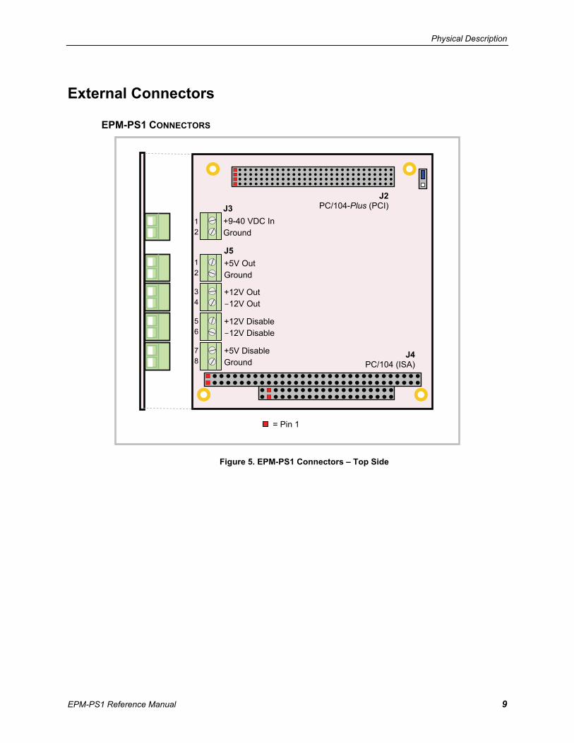
EPM-PS1 CONNECTORS
Figure 5. EPM-PS1 Connectors – Top Side
J2PC/104-Plus (PCI)
= Pin 1
J4 PC/104 (ISA)
J3 +9-40 VDC In Ground J5 +5V Out Ground
+12V Out -12V Out
+12V Disable -12V Disable
+5V Disable Ground
1 2
1 2
3 4
5 6
7 8
Physical Description
EPM-PS1 Reference Manual 10
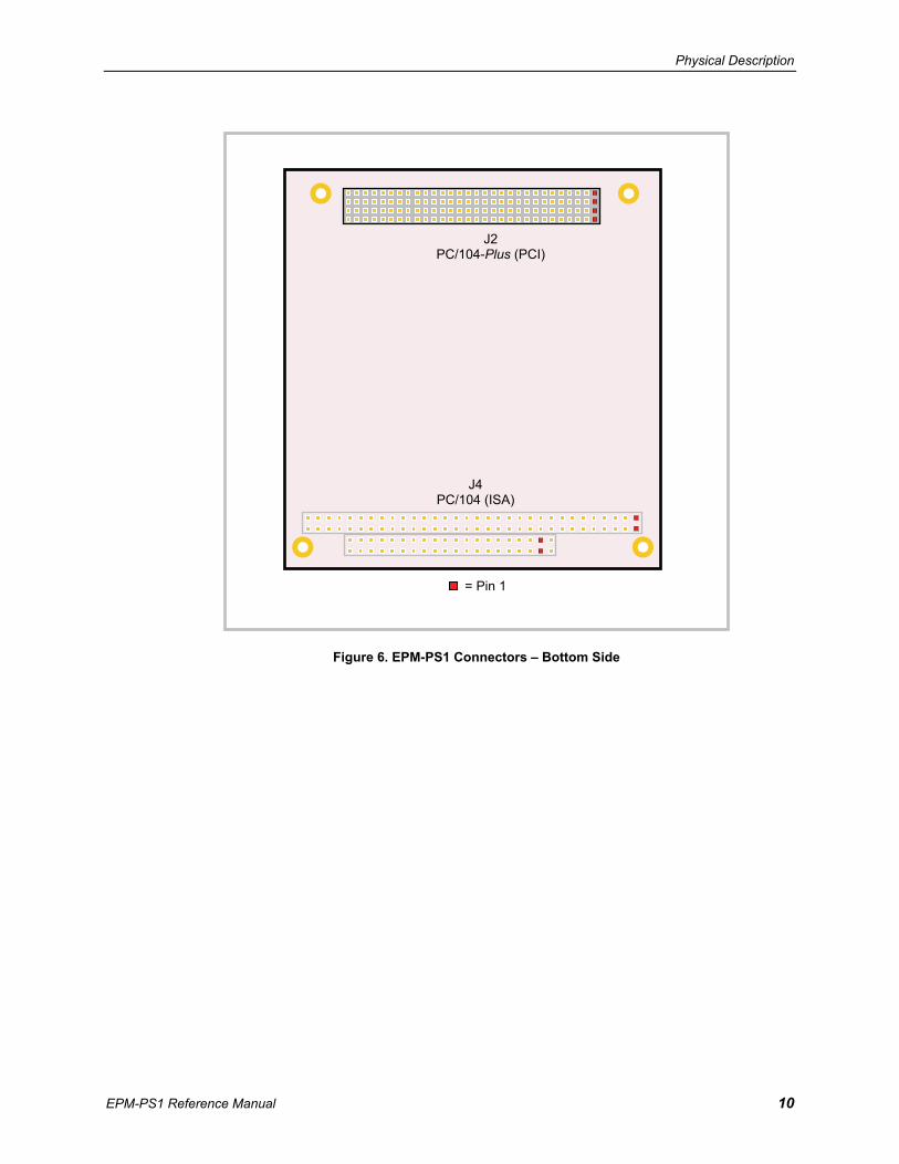
Figure 6. EPM-PS1 Connectors – Bottom Side
= Pin 1
J2 PC/104-Plus (PCI)
J4 PC/104 (ISA)

Physical Description
EPM-PS1 Reference Manual 11
EPM-PS1 CONNECTOR FUNCTIONS AND INTERFACE CABLES The following table notes the function of each connector, as well as mating connectors and cables, and the page where a detailed pinout or further information is available.
Table 1: Connector Functions and Interface Cables
Connector
Function
Mating Connector
Transition Cable
Cable Description Pin 1 Location1 x coord. y coord.
Page
J1 Factory use only – – – – – – J2 PC-104-Plus (PCI) AMP 1375799-1 – – 0.450 3.138 – J3 Power In – – Insulated wire2, AWG
16-14, to screw terminal 0.098 2.629 13
J4 PC/104 (ISA) AMP 1375795-2 – – 0.050 0.200 – J5 Aux Power Out and
PS Control – – Insulated wire2, AWG
16-14, to screw terminal 0.102 2.000 13, 16
1. The PCB origin is the mounting hole to the lower left, as oriented in Figure 5. 2. Wire insulation should be chosen based on the application and safety agency requirements.

Physical Description
EPM-PS1 Reference Manual 12
Jumper Block
JUMPERS AS-SHIPPED CONFIGURATION
Figure 7. Jumper Block Location – As Shipped Configuration
Table 2: Jumper Summary
Jumper Block
Description
As Shipped
Page
V1 Factory Use Only – This jumper must be installed or the EPM-PS1 will not operate.
[1-2] –
1
2
3
V1
EPM-PS1 Reference Manual 13
Operation
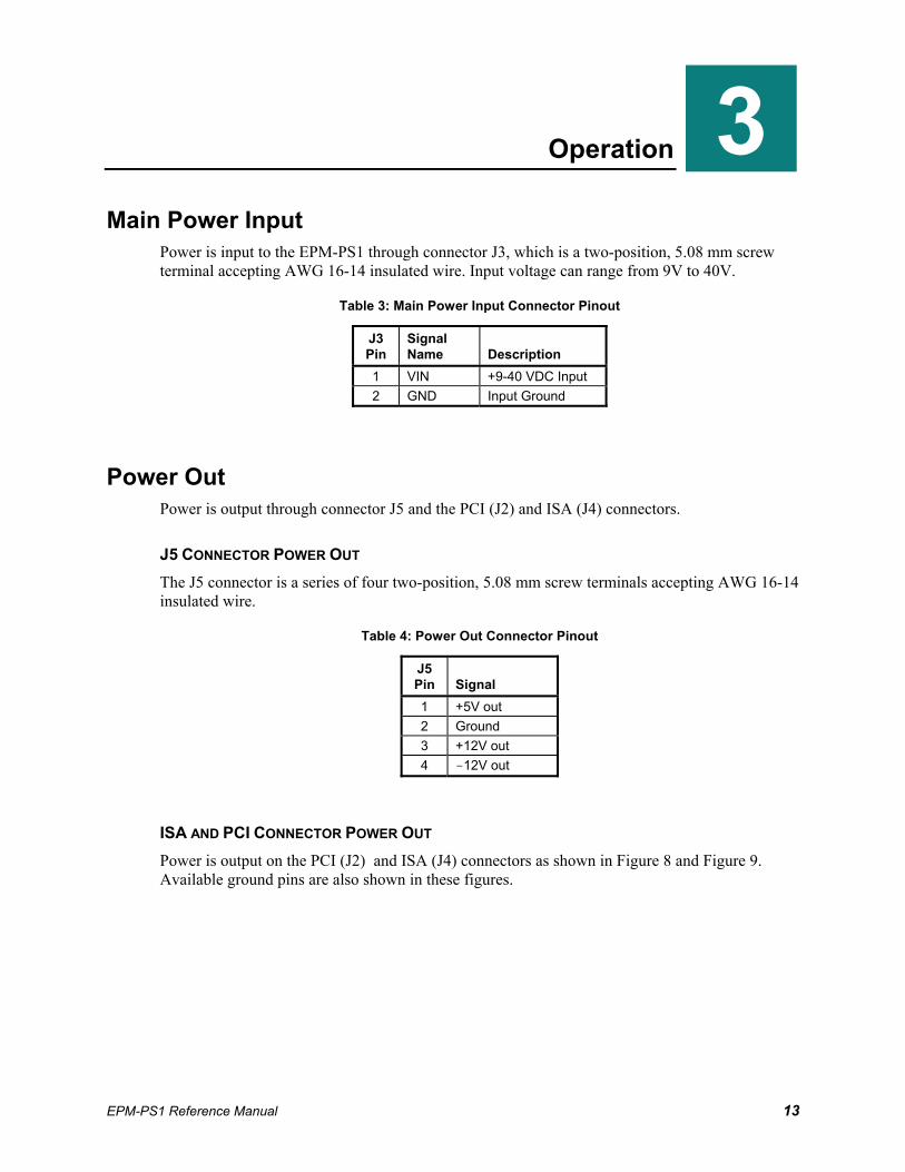
Main Power Input Power is input to the EPM-PS1 through connector J3, which is a two-position, 5.08 mm screw terminal accepting AWG 16-14 insulated wire. Input voltage can range from 9V to 40V.
Table 3: Main Power Input Connector Pinout
J3 Pin
Signal Name
Description
1 VIN +9-40 VDC Input 2 GND Input Ground
Power Out Power is output through connector J5 and the PCI (J2) and ISA (J4) connectors.
J5 CONNECTOR POWER OUT The J5 connector is a series of four two-position, 5.08 mm screw terminals accepting AWG 16-14 insulated wire.
Table 4: Power Out Connector Pinout
J5 Pin
Signal
1 +5V out 2 Ground 3 +12V out 4 -12V out
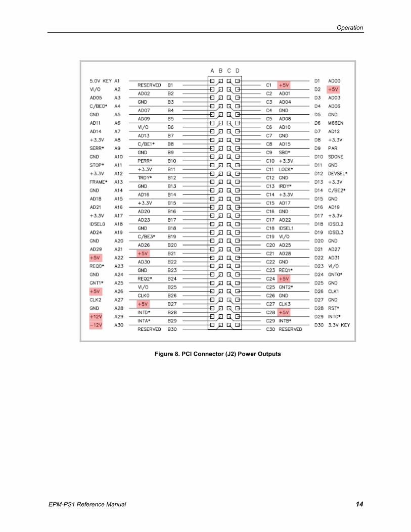
ISA AND PCI CONNECTOR POWER OUT Power is output on the PCI (J2) and ISA (J4) connectors as shown in Figure 8 and Figure 9. Available ground pins are also shown in these figures.
3
Operation
EPM-PS1 Reference Manual 14
Figure 8. PCI Connector (J2) Power Outputs

Operation
EPM-PS1 Reference Manual 15
Figure 9. ISA Connector (J4) Power Outputs
Operation
EPM-PS1 Reference Manual 16
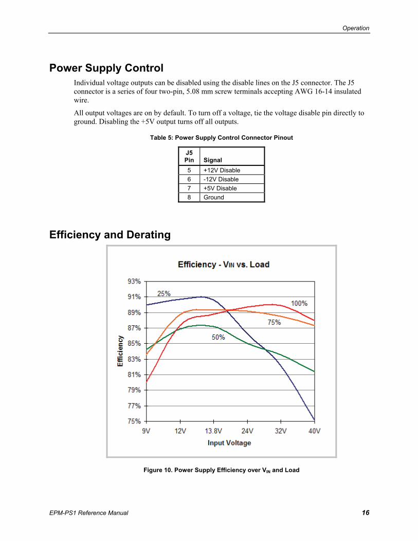
Power Supply Control Individual voltage outputs can be disabled using the disable lines on the J5 connector. The J5 connector is a series of four two-pin, 5.08 mm screw terminals accepting AWG 16-14 insulated wire.
All output voltages are on by default. To turn off a voltage, tie the voltage disable pin directly to ground. Disabling the +5V output turns off all outputs.
Table 5: Power Supply Control Connector Pinout
J5 Pin
Signal
5 +12V Disable 6 -12V Disable 7 +5V Disable 8 Ground
Efficiency and Derating
Figure 10. Power Supply Efficiency over VIN and Load
Operation
EPM-PS1 Reference Manual 17
Figure 11. Power Supply Derating Curve
Load
Pow
er
Ambient Temperature

EPM-PS1 Reference Manual 18
Appendix A – References
PC/104 Specification
PC/104-Plus Specification
A