Inexpensive experts in pineville chiropractor doctors (11 6 15)

Enviro‐Equipment Inc. 10120 Industrial Drive Pineville NC 28134
Stock#:226 Status: In stock Dimensions: 18”x8”x8” Weight: 50 lbs Description: Pump: MFG‐ Price Pumps Model‐ CD100B1 Serial‐ 9581456949‐09 Port size‐ 1.25” in 1” out Motor: MFG‐ Leeson Model‐ A6T34XC25F Serial‐ CAT#‐ 11193900 Frame‐ G56C Class‐ SF‐1 AMB‐ 40C HP‐1.5 RPM‐ 3450 Voltage‐ 208‐230/460 AMP‐ 4‐4.6/2‐2.3 Phase‐3 Hz‐60 DUTY‐Continuous CODE‐ K
US gpm
NPS
Hr
ft
8075706560555045403530252015100
5
5
10
15
20
Hea
d f
t
80757065605550450
10
40
20
35
30
30
40
50
25
60
20
70
15
80
90
10
100
5
110
4.94 in
4.5 in
4 in
3.5 in
3 in
0.5 hp 0.75 hp
1 hp
1.5 hp
2 hp
3 hp
30
30
35
35
40
40
45
45
50
50
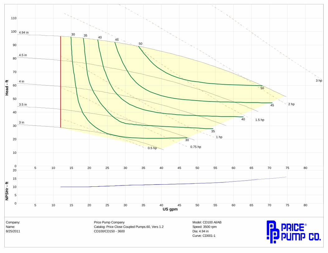
Company: Price Pump Company Model: CD100 Al/ABName: Catalog: Price Close Coupled Pumps.60, Vers 1.2 Speed: 3500 rpm8/25/2011 CD100/CD150 3600 Dia: 4.94 in
Curve: CD0011

Warning:
Before installing, repair-ing or performing main-tenance on this pump,read these instructionscompletely.
Disconnect power topump before servicingto avoid dangerous orfatal electrical shock .
Match supply voltage tomotor nameplate volt-age. Incorrect voltagecan cause fire or seriousmotor damage and voidwarranty.
Ground motor beforeconnection to electricalpower supply!! Failureto ground motor cancause severe or fatalelectrical shock!!Do not ground to gassupply line!!
Before disassemblingpump, be certain all liquid is removed. Ifpump was used to movehazardous or toxicmaterials, it must bedecontaminated prior todisassembly.
Close Coupled MotorPumps:
It is suggested that thesepumps be firmly bolted to alevel surface. Adequate airmovement around motorwill help prevent overheat-ing.Do not over tighten inletand outlet piping or volutemay fracture.
Power Frame MountedPumps
These pumps must bemounted on a rigid steelbase that will not warp orflex. Each pump must bemounted such that the pumpshaft centerline is on centerwith the driver shaft center-line. Pad and/or shims willbe required on either pump,driver or both.The twoshafts should not touch eachother and the distancebetween them depends onthe coupling used to connectthem.
Misalignment will causevibration, bearing failureand void warranty. Pumpsare rough aligned at the fac-tory but must be realignedafter shipment and installa-tion.
Pulley driven pump musthave pulleys inline and goodbelt tightness practices followed.
Direction of Rotation
Note: Motor shaft rotation isviewed from the suction endof pump. A rotational arrowis shown on the front of thepump volute casing.Incorrect rotation can causepump damage, failure orreduced performance, void-ing warranty. It is best tocheck rotation by momentar-ily energizing or jogging themotor prior to filling pumpwith liquid.
Warning! Do not operatepump without liquid formore than a few seconds,as damage will result tomechanical seal
Plumbing
All piping should be sup-ported independently of thepump. Piping should notexert any stress on the pumpconnections.
Price® Pump Co. Page revision-A ECO-919
Price® Pump Company
Type CD RCInstallation, Operating and
Maintenance Manual

Suction Piping(Horizontal Pumps)
Suction line must provideadequate suction pressureand smooth liquid flow forproper pump operation. Airin the suction line due toleaks or improper pipingdesign may cause the pumpto lose prime. Non-primingpumps must have their suc-tion flooded at start up.Also, the suction line mustprovide sufficient pressure(NPSH) and smooth flowto pump inlet to preventpump cavitation. The suc-tion pipe length enteringthe pump should be a mini-mum of 5 times and prefer-ably 10 times the pumpinlet diameter. Elbows, fit-tings or valves installedclose to the pump inlet candisrupt liquid flow andcause mal-function.Suction lines must be atleast the same diameter asthe pump inlet or larger ifpossible.
Price Pump Company rec-ommends against usingfoot valves in the suctionline to maintain liquid inthe pump when it’s notoperating. If foot valves areused, due to suction liftconditions, they must beproperly maintained toavoid leaks resulting fromwear or fouling. Suctionpiping must be designed toprevent vapor from beingtrapped in high spots in thepiping. This condition maycause the pump to vaporlock.
Discharge Piping
To control flow and dis-charge head, it is advisableto install a valve (globe,ball, or other adjustableand non-leak type) in thedischarge line close to thepump. The valve may beclosed during systemrepairs to prevent back-flow. By installing a checkvalve in the discharge linebackflow can also be pre-vented during maintenanceor during periods of pumpstoppage.
Operation
All centrifugal pumps mustbe filled with liquid priorto start up. It is suggestedthat during initial start upthe discharge valve beclosed and then opened asthe motor develops fullrpm’s. If pump does notbuild up pressure as motorspeed increases, shut downand make sure that liquidflow into pump is notrestricted (see“Troubleshooting”).
Note: A centrifugalpumps flow and head(pressure) will vary withthe amount of resistance(friction and flow restric-tions) in the discharge line.As a valve on the dischargeline opens the flow andmotor amp draw willincrease and head (pres-sure) will drop. As a valveon the discharge is closedthe flow and amp draw willdecrease and the head will
increase.
If resistance in the dis-charge line is not sufficientthe pump will operate at acondition of maximumflow, also sometimes called"end of performancecurve." Maximum horse-power is required to oper-ate at this point and motoroverload may result. Ifexcessive amp draw andmotor overload is re-curring, reduce the systemflow by installing a valveor orifice in the dischargeline and restrict flow.Alternatively, reduce pumphead by trimming impellerto a smaller diameter.
Consult local Price Pumpdistributor for assistance.
Price® Pump Co. Page revision-A ECO-919

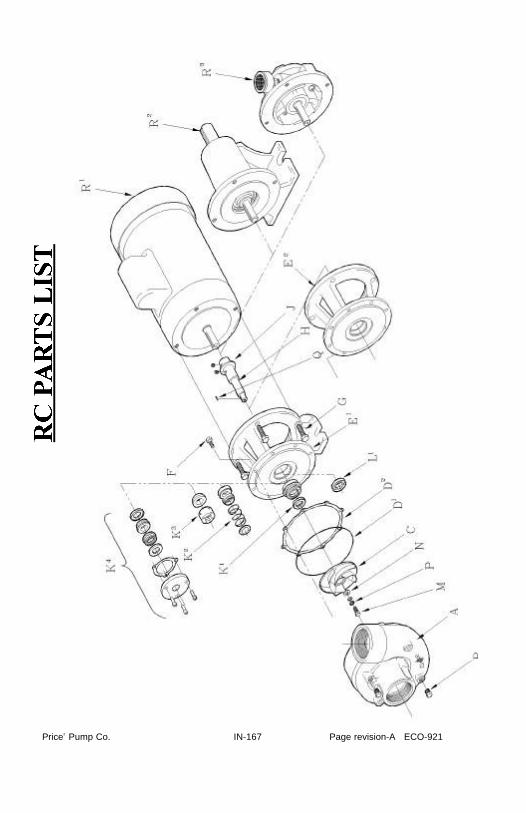
Price® Pump Co. IN-167 IN-167 Page revision-A ECO-921
DISASSEMBLY 1.Disconnect power
source to motor.2.Disconnect electrical
connections taggingwires carefully to pre-serve correct rotation.Loosen motor base.
3.Remove pump andmotor assembly torepair area.
4.Remove volute frompump.
5.Unscrew and removeimpeller lockdownand lockwashers.Slide impeller offshaft. Do Not throwshaft key away.
6.Remove seal headfrom the shaft. Type6A: Remove sealhead from bracket.Type 21: Slide sealhead from the shaft.Type 9: Loosen setscrews and slide sealhead off shaft.
7.Remove four motorbolts and removebracket from motor.
8.Remove seal seat frombracket. Use woodenor plastic dowel totamp the seat from thebracket.REASSEMBLY
1.Clean seat cavity ofthe bracket thorough-ly.
2.Thoroughly cleanpump shaft. Assurethat the shaft is notgrooved and that thereis no evidence of pit-ting or fretting. If theshaft is grooved, fret-ted or worn, replace it.
3.Install the pump shaftonto the motor shaft,aligning set screws ofthe pump shaft withthe keyway of themotor shaft. Installslinger between thepump shaft setscrews.
4.For Type 6Aa. Place bracket on
firm surface withseat cavity (pumpend) up. Using atool (1-19/64"ID x1-5/8" OD x 1/2"deep), press sealinto seal cavity withcarbon face of seal(volute end up) up.Press until flange isseated in seal cavityof bracket. Pressonly on outer flangeof seal. Avoidtouching carbonsurface.
b. Place bracket onmotor (aligning thebase if applicable).Secure bracket withfour motor bolts.
c. Pull pump shaft for-ward until shoulderof pump shaft con-tacts back of brack-et and slightly snugone setscrew to holdshaft in place.
d. Apply small amountof vegetable oil onthe pump shaft andI.D. of seat elas-tomer. Gently placeseat on end of shaftwith ceramic facedown toward seal.After slidingimpeller onto shaft,seat will be properlylocated.
e. Slide impeller ontoshaft ensuring seatis pushed flush withshoulder of shaftand impeller hub.
f. Install shaft key,impeller flatwasher,lockwashers andlockdown bolt.
TYPE CD/RC MAINTENANCE AND REPAIRBefore attempting any repairs under warranty, contact Distributor to obtain fac-tory authorization. Repairs carried out without authorization may void warranty.Many causes of pump system failure are due to improper system design. Referto the trouble shooting list in this manual before carrying out pump inspection.

Tighten securely(10ft.lbs.) Caution:Serviceable Loctite mustbe used on lockdownbolt. Lockwasher pairsmust be assembled camface to cam face. Seediagram
g. Loosen pump shaftset screw.
h. Install new volutegasket/o-ring andmount volute tobracket. Securewith bolts and tight-en evenly.
i. Setting impellerclearance: Slidepump shaft forwarduntil impeller touch-es volute. Slideshaft back .010-.015". Tightenpump shaft setscrews. Turn shaftby hand to ensureimpeller does notrub against volute.Proceed to step 9.
5.For Type 21, 8, 9seals: Place the brack-et on a firm surfacewith the seat cavity(pump end) up. Thenplace a small amountof vegetable oil on theseat cup or o- ringseat. Place the seat inthe seat cavity withthe polished face uptoward the pump end.Evenly push seat intocavity with fingersthen gently tap seatinto place with a
wooden dowel or plas-tic rod (1-1/8" outsidediameter). To helpensure the seat is notdamaged place thecardboard disk sup-plied with the sealover the seat face.
6.Place bracket onmotor (aligning thebase if applicable).Secure bracket withfour motor bolts.
7.Pull pump shaft for-ward until shoulder ofpump shaft contactsback of bracket andslightly snug onesetscrew to hold shaftin place
8.Install seal headassembly
For Type 21 Seals:a. Lubricate shaft and
elastomer with veg-etable oil.
b. Install rotary sealhead onto pumpshaft and slidetoward seat untilcarbon face contactsceramic seat.
c. Install seal springand retainer.
d. Install impeller.Install key in pumpshaft. Slideimpeller onto shaftensuring that thespring retainer doesnot slip between theshoulder of the shaftand the hub of theimpeller. Installimpeller flatwasher,
lockwashers andlockdown. Tightensecurely (10 ft. lbs.)Caution:Serviceable Loctitemust be used onlockdown bolt.Lockwasher pairsmust be assembledcam face to camface. See diagram
e. Loosen pump shaftset screw.
f. Install new volutegasket/o-ring andmount volute tobracket. Securewith bolts and tight-en evenly.
g. Slide pump shaftforward untilimpeller touchesvolute. Slide shaftback with a screw-driver .010-.015".Tighten pump shaftset screws. Turnshaft by hand toensure impellerdoes not rub againstvolute. Proceed tostep 9.
For Type 8 & 9 Seals: a. Install impeller.
Install key in pumpshaft. Slideimpeller onto shaftand install impellerwasher and lock-down bolt. Tightensecurely.
Price® Pump Co.IN-167 IN-167 Page revision A ECO-921

Price® Pump Co. IN-167 Page revision-A ECO-921
b. Loosen pump shaftset screw.
c. Install new volutegasket/o-ring andmount volute tobracket. Tighten atleast two bolts atthis time.
d. Slide pump shaftforward untilimpeller touchesvolute. Slide shaftback .010"-.015".Tighten pump shaftset screws. Turnshaft by hand toensure impellerdoes not rub againstvolute.
d. Remove volute andimpeller.
e. Install seal headonto pump shaftsliding gently pastshoulder of shaft.Slide seal headtoward seat untilcarbon face contactsceramic seat.Tighten seal headsetscrews to pumpshaft. Remove clipsin seal head and dis-card.
j. Reinstall impeller,flatwasher, lock-washers and lock-down bolt. Tightensecurely (10 ft. lbs.)Caution:Serviceable Loctite must be used onlockdown bolt.Lockwasher pairsmust be assembled
cam face to camface. See diagram
k. Install new volutegasket and mountvolute to bracket.Secure with boltsand tighten evenly.
l. Rotate pump shaftby hand to ensureimpeller does notrub against volute.
9.Return pump to instal-lation, reconnect elec-tric connections.
10.Start pump momen-tarily to observe shaftrotation. If rotationcorresponds to therotation arrow, pumpmay be put into serv-ice. If rotation isincorrect, switch anytwo leads on 3-phasemotors. Check wiringdiagram of motor forsingle phase rotation.
11. Remove top pipeplug (if applicable)from the front ofvolute and primepump thoroughly,making sure all airis purged.
12. Start pump allowingadequate time topurge all air fromsystem. Observeany gauges, flowmeters, etc. to seeof pump performsproperly.
LOCKDOWN ASSEMBLY
DIAGRAM A

Double Seal Installation
REASSEMBLY1. Clean seat cavity of the
bracket and seal platethoroughly.
2. Thoroughly clean pumpshaft. Assure that theshaft is not grooved andthat there is no evidenceof pitting or fretting.Polish the shaft withextra fine emery clothand clean the keyway. Ifthe shaft is grooved,fretted or worn, replaceit.
3. Install the pump shaftonto the motor shaft,aligning set screws ofthe pump shaft with thekeyway of the motorshaft. Ensure all debrisand burrs are removedfrom the motor shaftand that the slinger is inplace.
4. Place bracket on motor(aligning the base ifapplicable). Securebracket with four motorbolts.
5. Pull out pump shaft asfar as it will go towardvolute end and slightlysnug one set screw tohold shaft in place
6. Place a small amount ofvegetable oil on the seatcup. Install seats intoseat plate and bracketwith polished faces up.Evenly push seat intoseat cavity with fingers,then gently tap seat intoplace with a woodendowel or plastic rod (1-1/8” outside diameter).
To help ensure the seatis not damaged, placethe cardboard disk sup-plied with the sealunder the end of thedowel to prevent dam-aging the seat face.
7. Install seal head assem-bly:For Type 21:a. Lubricate shaft and
elastomer with veg-etable oil.
b. Install first rotary sealhead onto pump shaftand slide toward seatusing a twistingmotion until carbonface touches seal seat.
d. Install second rotaryseal head onto shaftsleeve with carbonfacing towards pumpend.
8. Install seal plate ontopump end of bracketwith new gasket andtighten three allen cap-screws evenly (note:use Teflon pipe sealanton bolts).
9. Install impeller:a. Install key in pump
shaft. b. Slide impeller onto
shaft.c. Install impeller wash-
er and lockdown.Tighten.
10. Loosen pump shaftset screw.
11. Install new volutegasket, or O-ring andmount volute . Securewith bolts and tightenevenly.
12. Move shaft back witha screwdriver .010-
.015". Tighten pumpshaft set screws. Turnshaft by hand toensure impeller doesnot rub againstvolute.
13. Return pump toinstallation, reconnectelectric connections.
14. Start pump momen-tarily to observe shaftrotation. If rotationcorresponds to therotation arrow on thepump, it may be putinto service. If rota-tion is incorrect,switch any two leadson 3-phase motors tochange rotation.Check wiring dia-gram of motor forsingle phase rotationcorrection.
15. Remove top pipe plug(if applicable) fromthe front of voluteand prime pump thor-oughly, making sureall air is purged.Turn shaft one revo-lution and then refill.Replace the pipeplug.
16. Start pump allowingadequate time topurge all air fromsystem. Observe anygauges, flow meters,etc., to see if pumpperforms properly.
Price® Pump Co. IN-167 Page revision-A ECO-921
Price® Pump Co. IN-167 Page revision-AECO-921
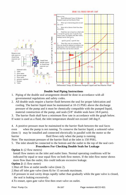
Double Seal Piping Instructions1. Piping of the double seal arrangement should be done in accordance with all
governmental regulations and safety codes.2. All double seals require a barrier flush between the seal for proper lubrication and
cooling. The barrier liquid must be maintained at 10-15 PSIG above the discharge pressure of the pump and it must be chemically compatible with the pumped liquid, material construction of the pump, and seals (5/8" double seals have 18-8 parts).
3. The barrier flush shall have a minimum flow rate in accordance with the graph below.If water is used as a fluid, the inlet temperature should not exceed 140 deg F.
4. A positive pressure must be maintained to the barrier flush between the seal faceseven when the pump is not running. To conserve the barrier liquid, a solenoid valve(item 1) may be installed and connected electrically in parallel with the motor so thebarrier fluid flows only when the pump is running.Note: The maximum pressure of the barrier fluid at the inlet is 150 PSIG.5. The inlet should be connected to the bottom and the outlet to the top of the seal cavi-
Procedures For Checking Double Seals for LeakageOption 1: (2 flow meters)
Install flow meters on the inlet and outlet lines. Normal operating conditions will be indicated by equal or near equal flow on both flow meters. If the inlet flow meter shows more flow than the outlet, this could indicate excessive leakage.
Option 2: (1 flow meter)1.Shut off flow at outlet needle valve (item 2).2.Shut off inlet gate valve (item 8) for 15 seconds maximum.3.If pressure in seal cavity drops rapidly rather than gradually while the gate valve is closed,
the seal is leaking excessively.4.To restart, open gate valve first then reset valve on outlet.
. Solenoid valve2. Valve3. Flow meter4. Pressure gauge5. Flow meter6. pressure regulator7. Strainer8. Valve
Return to out-side source orclosed loopreservoir sys-tem Liquid from
outside sourceor closed loopreservoir sys-tem
How to Use:1. Read Differential Temp. (F) BetweenPumped Liquid and Seal Barrier Fluid.
2. Move up to intersecting point on seal-size curve.
3. Move left to Barrier Fluid Flow Rate(US-GPM).
4. Fluid flow rate is based on a fluid witha 1.0 specific gravity and 1.0 specific heat,such as water. For liquids with other values,multiply barrier fluid rate by
1specific gravity x specific heat
5. These flow rates are estimates.Theflow rate should be adjusted according to thetemperature of the seal chamber outlet oncethe initial flow rate has been selected
Differential Temp. (F) Between Pumped Liquid and Seal Barrier Fluid
OUT
Price® Pump Co. IN-167 Page revision-A ECO-921

Price Pump Co. IN-167

Price® IN-167 Page revision-A ECO-921
Price® Pump Co. IN-167 Page revision-A ECO-921

Price® Pump Co. IN-167 Page revision-A ECO-921

Price® Pump Co.IN-167 IN-167 Page revision A ECO-921

Price® Pump Co. Type IN-167 IN-167 Page revision-A ECO-921

1.Pump fails to buildpressure:Check for:
a.Pump not primed.b.Incorrect rotation.c.Driver speed too
low.d.Suction line restrict-
ed.e.Driver failure.f. Plugged or damaged
impeller.g.Pump or impeller
undersized.h.Pump cavitation.i. Improper impeller
clearance.
2.Pump fails to pro-vide enough flow.Check for:
a.System resistancetoo high.
b.Pump undersized.c.Pump not primed.d.Driver speed too
low.e.Poor suction condi-
tions.f. Improper impeller
clearance.
3.Excessive noise orvibration duringoperation.Check for:
a.Motor bearing fail-ing.
b.Pump cavitating.c.Improper impeller
clearance.
4.Leaking mechani-cal seal.Check for:
a. Improper assembly.b.Worn or cracked
seal faces.c.Abrasive material in
fluid.d.Liquid flashing at
seal faces (fluidtemperature toohigh).
e.Seal pressure ratingtoo low for the serv-ice.
f. Chemical attack ofseal parts.
g.Seal operated dry orwith a liquid havingpoor lubricatingproperties.
5.Pump graduallyloses pressure andhead.Check for:
a. Increasing tempera-ture causing cavita-tion or liquid vapor-ization.
b.Driver failure.c.Suction lift toohigh.d.Air entering suction
line.
6.Motor/pump over-heating.Check for:
a.Excessive flow andamp draw (Throttledischarge).
b.Low voltage or fre-quency.
c.Flow too low withresulting heat rise.
d.Bearing failure.e.System temperature
too high.
TROUBLESHOOTING
If all else fails, call your distributor or Price Pump @ (707) 938-8441
Price® Pump Co. Page revision-A ECO-919

Price® Pump Co. Page revision-A ECO-919
General Terms Of Sale For ProductsEffective: January 1, 2001
1. GENERAL A. Seller's price is based on these sales terms andconditions. This contract shall represent the final,complete and exclusive statement of the agreementbetween the parties and may not be modified, sup-plemented, explained or waived by parol evidence,any Terms and Conditions contained in Buyer'spurchase order or request for quotation, any courseof dealings between the parties, Seller's perform-ance or delivery, or in any other way. The Termsand Conditions of this contract may only be modi-fied or waived in a written document signed by anOfficer of Seller. These terms are intended to coverall activity of Seller and Buyer hereunder, includ-ing sales and use of products, parts and work andall related matters (references to products includeparts and references to work include construction,installation and start-up). Any reference by Sellerto Buyer's specifications and similar requirementsare only to describe the products and work coveredhereby and no warranties or other terms thereinshall have any force of effect. Any informationprovided by Seller including, but not limited to,suggestions as to specific equipment does notimply any guarantee of specific suitability and/ormaterial compatibility in a particular application,since many factors outside the control of Sellermay affect the suitability of products in a particularapplication. Catalogs, circulars and similar pam-phlets of the Seller are issued for general informa-tion purposes only and shall not be deemed tomodify the provisions hereof. B. The agreement formed hereby and the languageherein shall be construed and enforced under theUniform Commercial Code as in effect in the Stateof California on the date hereof.
2. TAXES Any sales, use or other similar type taxes imposedon this sale or on this transaction are not includedin the price. Such taxes shall be billed separatelyto the Buyer. Seller will accept a valid exemptioncertificate from the Buyer if applicable; however, ifan exemption certificate previously accepted is notrecognized by the governmental taxing authorityinvolved and the Seller is required to pay the taxcovered by such exemption certificate. Buyeragrees to promptly reimburse Seller for the taxespaid.
3. PERFORMANCE, INSPECTION ANDACCEPTANCE
A. Unless Seller specifically assumes installation,construction or start-up responsibility, all productsshall be finally inspected and accepted within thirty(30) days after arrival at point of delivery.Products not covered by the foregoing and all workshall be finally inspected and accepted with thirty(30) days after completion of the applicable workby Seller. All claims whatsoever by Buyer,(including claims for shortages) except only thoseprovided for under the WARRANTY AND LIMI-TATION OF LIABILITY and PATENTS Clauses,hereof, must be asserted in writing by Buyer withinsaid thirty (30) day period or they are waived. Ifthis contract involves partial performance, all suchclaims must be asserted within said thirty- (30) dayperiod for each partial performance. There shall beno revocation of acceptance. Rejection may beonly for defects substantially impairing the value ofproducts or work and Buyer's remedy for lesserdefects shall be those provided for under the WAR-RANTY AND LIMITATION OF LIABILITYClause. B. Seller shall not be responsible for non-perform-ance or for delays in performance occasioned byany causes beyond Seller's reasonable control,including, but not limited to, labor difficulties,delays of vendors or carriers, fires, governmentalactions, or shortages of material, components,labor, or manufacturing facilities. Any delays sooccasioned shall affect a corresponding extensionof Seller's performance dates, which are, in anyevent, understood to be approximate. In no eventshall Buyer be entitled to incidental or consequen-tial damages for late performance or for a failure toperform. Seller reserves the right to make partialshipments and to ship products, parts or work
which may be completed prior to the scheduledperformance date. C. In the event that Seller has agreed to mountmotors, turbines, gears, or other products which arenot manufactured by Seller and which are not anintegral part of Seller's manufactured product, anda delay in the delivery of such products to Selleroccurs that will cause a delay in Seller's perform-ance date, Seller reserves the right to ship its prod-uct upon completion of manufacture and to refundan equitable portion of the amount originallyincluded in the purchase price for mounting with-out incurring liability for non-performance. D. Seller reserves to itself the right to change itsspecifications, drawings and standards if suchchanges will not impair the performance of itsproducts, and parts, and further that such products,and parts, will meet any of Buyer's specificationsand other specific product requirements which area part of this agreement. E. The manufacture and inspection of productsand parts shall be to Seller's Engineering andQuality Assurance standards plus such otherinspections or tests of documentation as are specifi-cally agreed to by Seller. Requirements for anyadditional inspection, tests, documentation, orBuyer witness of manufacture, test, and/or inspec-tion shall be subject to additional charges.
4. TITLE AND RISK OF LOSS Title and risk of loss shall pass to buyer upondelivery of products at the designated "Ex Works"as defined by Incoterms 1990, unless other wiseagreed by the parties.
5. EROSION AND CORROSION It is specifically understood that products and partssold hereunder are not warranted for operation witherosive or corrosive fluids. No product or partshall be deemed to be defective by reason of failureto resist erosive or corrosive action of any fluid andBuyer shall have no claim whatsoever againstSeller therefore.
6. WARRANTY AND LIMITATION OFLIABILITY.
A. Seller warrants only that its product and parts,when shipped, will be free from defects in materi-als and workmanship. With respect to productsand parts not manufactured by Seller, Seller's onlyobligation shall be to assign to Buyer, to the extentpossible, whatever warranty Seller requires fromthe manufacturer. All claims for defective productsor parts under this warranty must be made in writ-ing immediately upon discovery and, in any event,within one (1) year after initial start-up or eighteen(18) months after shipment, whichever first occurs,and all claims for defective work must be made inwriting immediately upon discovery and in anyevent, within one (1) year of completion thereof bySeller.Defective items must be held for Seller's inspectionand returned to the sellers'- point of original ship-ment upon request. UNAUTHORIZED DISASSEMBLY OR TAM-PERING WITH ANY PRODUCT OR COMPO-NENT MAY VOID ITS WARRANTY.THE FOREGOING IS EXPRESSLY IN LIEU OFALL OTHER WARRANTIES WHATSOEVER,EXPRESS, IMPLIED AND STATUTORY,INCLUDING WITHOUT LIMITATION, THEIMPLIED, WARRANTIES OF MER-CHANTABILITY AND FITNESS.
B. ANY PRODUCT (S) SOLD HEREUNDERWHICH IS NOT MANUFACTURED BY SELL-ER IS NOT WARRANTED BY SELLER and shallbe covered only by the express warranty, if any, ofthe manufacturer thereof.
C. Upon Buyer's submission of a claim as provid-ed above and its substantiation, Seller shall at itsoption either (i) repair or replace its product, partor work at the original place of shipment, or (ii)refund an equitable portion of the purchase price.
D. THE FOREGOING IS SELLER'S ONLY
OBLIGATION AND BUYER'S EXCLUSIVEREMEDY FOR BREACH OF WARRANTYAND, EXCEPT FOR GROSS NEGLIGENCE,WILLFUL MISCONDUCT, AND REMEDIESPERMITTED UNDER THE PERFORMANCE,INSPECTION AND ACCEPTANCE AND THEPATENTS CLAUSES HEREOF, THE FOREGO-ING IS BUYER EXCLUSIVE REMEDYAGAINST SELLER FOR ALL CLAIMS ARIS-ING HEREUNDER OR RELATING HERETOWHETHER SUCH CLAIMS ARE BASED ONBREACH OF CONTRACT. TORT (INCLUDINGNEGLIGENCE) OR OTHER THEORIES.BUYER'S FAILURE TO SUBMIT A CLAIM ASPROVIDED ABOVE SHALL SPECIFICALLYWAIVE ALL CLAIMS FOR DAMAGES OROTHER RELIEF, INCLUDING BUT NOT LIM-ITED TO CLAIMS BASED ON LATENTDEFECTS. IN NO EVENT SHALL BUYER BEENTITLED TO INDIRECT, SPECIAL, INCIDEN-TAL OR CONSEQUENTIAL DAMAGES, NORFOR DAMAGES FOR LOSS OF USE, LOSTPROFITS OR REVENUE, INTEREST, LOSTGOODWILL, WORK OR PRODUCTION STOP-PAGE, IMPAIRMENT OF OTHER GOODS,INCREASED EXPENSES OF OPERATION, ORTHE COST OF PURCHASING REPLACEMENTPOWER OR OTHER SERVICES BECAUSE OFSERVICE INTERRUPTIONS. FURTHERMORE,IN NO EVENT SHALL SELLER'S TOTAL LIA-BILITY FOR DAMAGES OF BUYER EXCEEDTHE PURCHASE PRICE OF THE PRODUCTSOR PARTS MANUFACTURED BY SELLERAND UPON WHICH SUCH LIABILITY ISBASED. ANY ACTION ARISING HEREUN-DER RELATED HERETO, WHETHER BASEDON BREACH OF CONTRACT, TORT (INCLUD-ING NEGLIGENCE) OR OTHER THEORIES,MUST BE COMMENCED WITHIN ONE (1)YEAR AFTER THE CAUSE OF ACTIONACCRUES OR IT SHALL BE BARRED.
7. PURCHASER'S REPRESENTATIONS &WARRANTIES
Purchaser represents and warranties that the prod-ucts(s) covered by this contract shall not be used inor in connection with a nuclear facility or applica-tion. The parties agree that this representation andwarranty is material and is being relied on by sell-er. This provision may be modified in a separatewriting signed by an officer of Price Pump Co.
8. PATENTS Seller agrees to assume the defense of any suit forinfringement of any patents brought against Buyerto the extent of such suit charges infringement ofan apparatus or product claim by Seller's product inand of itself, provided (i) said product is builtentirely to Seller's design, (ii) Buyer notifies Sellerin writing of the filing of such suit within ten (10)days after the service of process thereof, and (iiiz e) Seller is given complete control of the defense ofsuch suit, including the right to defend, settle andmake changes in the product for the purpose ofavoiding infringement of any process or methodclaims, unless infringement of such claims is theresult of following specific instruction furnished bySeller.
9. EXTENT OF SUPPLY Only products as listed in Seller's proposal areincluded in this agreement. It must not be assumedthat Seller has included anything beyond same.
10. MANUFACTURING SOURCES To maintain delivery schedules, Seller reserves theright to have all or any part of the Buyer's ordermanufactured at any of Sellers', sellers' licensees orsub contractors' plants, globally.
11. TERMS OF PAYMENT Net 30 days from date of invoice.