ENIGMA IP2 Monitoring Receiver If you use this unit as an IP receiver card, please use the manual of...
15
ENIGMA IP2 Monitoring Receiver (and IP receiver card) Programming Manual 6 / 11 / 2014
Transcript of ENIGMA IP2 Monitoring Receiver If you use this unit as an IP receiver card, please use the manual of...
ENIGMA IP2
Monitoring Receiver
(and IP receiver card)
Programming Manual
6 / 11 / 2014

CONTENT
1. INTRODUCTION.......................................................................................................................3
2. SYSTEM STRUCTURE.............................................................................................................4
3. FIRST STEPS..............................................................................................................................4
Connectors and LED signals.......................................................................................................5
4. SYSTEM PROGRAMMING WITH PC SOFTWARE...............................................................6
5. TROUBLESHOOTING...............................................................................................................8
6. ENIGMA IP2 TESTING.............................................................................................................9
7. FIRMWARE UPGRADE AND OTHER FUNCTIONS...........................................................11
8. SYSTEM MESSAGES..............................................................................................................13
9. COMPATIBILITY.....................................................................................................................14
10. TECHNICAL DATA................................................................................................................15
2

1. INTRODUCTION
Thank you for choosing our product. This modern and reliable monitoring receiver not
only guarantees the highest level of security, but also it is a useful colleague in the life
of every monitoring company, because of its user-friendly handling and intelligent
functions.
To use the highest range of provided functions please read carefully the Installer
Manual.
For the confident programming and secure usage please keep all warnings in Installer
Manual, with highly focusing to security directions.
Note: If you use this unit as an IP receiver card, please use the manual of Enigma II
receiver.
3
2. SYSTEM STRUCTURE
The Enigma IP2 monitoring receiver is ideal and cost-effective solution to build-up a
monitoring station, where transmission is sent only through IP / GPRS channel. Device
has compact size and excellent parameter setting possibilities. The incoming IP
communication might be monitored according to client accounts. It provides prominent
protection level for the reliable and secure operation. The card version device can be be
built into the Enigma II base unit. With combination of a suitable monitoring software it
guarantees not only reliable signal transmission, but also easy to use operator interface.
3. FIRST STEPS
Please unpack the device carefully and please check is there any damage on that
caused by transport. If there is any obvious damage do not switch on the device, please
call the distributor. The basic package contains the following units:
• ENIGMA IP2 monitoring receiver
• USB cable for PC connection
• 12 VDC power supply set
• Installer Manual
Before mounting the device to its operation environment, receiver test is recommended.
4
Connectors and LED signals
There are the following connectors on the backside of the receiver:
Power supply connector: 12 VDC power supply connector (always use the original
power supply unit provided by manufacturer).
Note: In case of the failure of main power supply unit, the device is able to operate with
power received through USB cable (if USB current is suitable). But long term usage
without main power supply unit is not recommended.
Ethernet connector: 100 Mbit Ethernet connector for network cable.
Mini USB connector: To connect of the USB port of monitoring PC (serial comm).
RS232 connector (only in newer version IP2 receiver): To connect to monitoring PC
(serial communication).
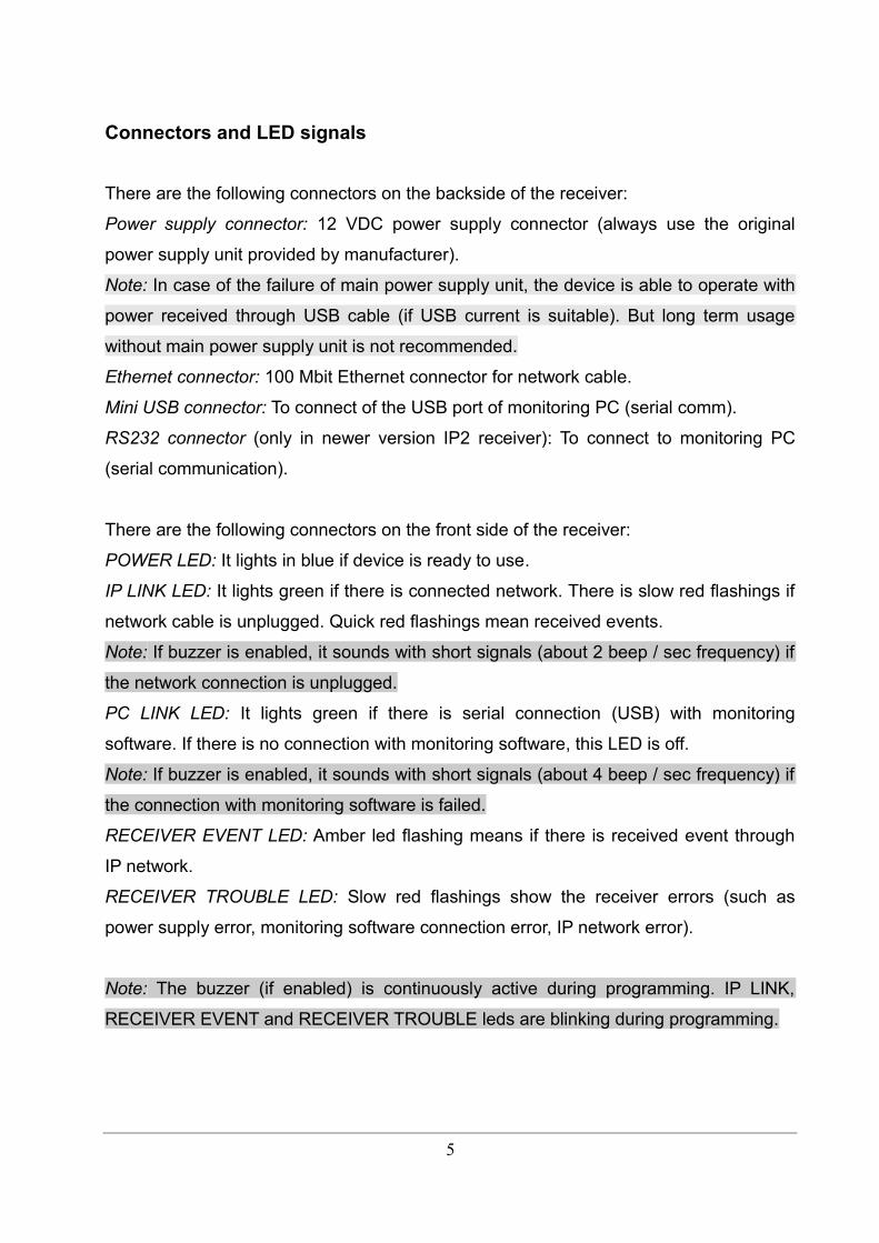
There are the following connectors on the front side of the receiver:
POWER LED: It lights in blue if device is ready to use.
IP LINK LED: It lights green if there is connected network. There is slow red flashings if
network cable is unplugged. Quick red flashings mean received events.
Note: If buzzer is enabled, it sounds with short signals (about 2 beep / sec frequency) if
the network connection is unplugged.
PC LINK LED: It lights green if there is serial connection (USB) with monitoring
software. If there is no connection with monitoring software, this LED is off.
Note: If buzzer is enabled, it sounds with short signals (about 4 beep / sec frequency) if
the connection with monitoring software is failed.
RECEIVER EVENT LED: Amber led flashing means if there is received event through
IP network.
RECEIVER TROUBLE LED: Slow red flashings show the receiver errors (such as
power supply error, monitoring software connection error, IP network error).
Note: The buzzer (if enabled) is continuously active during programming. IP LINK,
RECEIVER EVENT and RECEIVER TROUBLE leds are blinking during programming.
5

4. SYSTEM PROGRAMMING WITH PC SOFTWARE
To use the monitoring receiver with monitoring PC connect the mini USB port of receiver
to the USB port of the monitoring PC. Driver installation is automatic (from Windows 7).
After this the appropriate monitoring software settings should be done (it means usually
the serial port and baud rate settings).
The process is the following in AlarmSyS monitoring software:
Start Alarm Start software → Start Alarm Setup and log in (ID: 1, Password: 1) → Setup
menu → Hardware Setup → Digital Receiver #1.
In pop-up window basically only Receive and process incoming messages option
should be enabled, then set the proper COM port (checking in Windows OS: Control
Panel / Hardware / Device Manager) and Baud Rate to 57600, then apply changes.
After this receiver events are displayed on monitoring software screen.
Note: To connect IP2 card to monitoring software set Baud Rate value to 57600 in
monitoring software settings.
6
In normal case programming of the monitoring receiver unit can be done through USB
(serial) port. After completing appropriate IP settings programming can be done through
Ethernet network as well. Please use EniTerm software for programming. The
programming steps are bellow:
1. Please start EniTerm software.
2. Choose the ET (settings) file according to the device what you want to program:
- IP.et – IP2 Ethernet receiver card programming
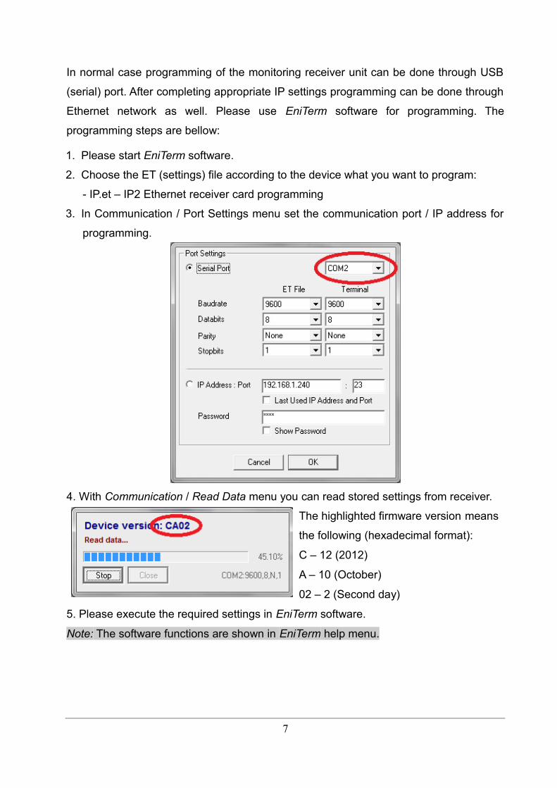
3. In Communication / Port Settings menu set the communication port / IP address for
programming.
4. With Communication / Read Data menu you can read stored settings from receiver.
The highlighted firmware version means
the following (hexadecimal format):
C – 12 (2012)
A – 10 (October)
02 – 2 (Second day)
5. Please execute the required settings in EniTerm software.
Note: The software functions are shown in EniTerm help menu.
7
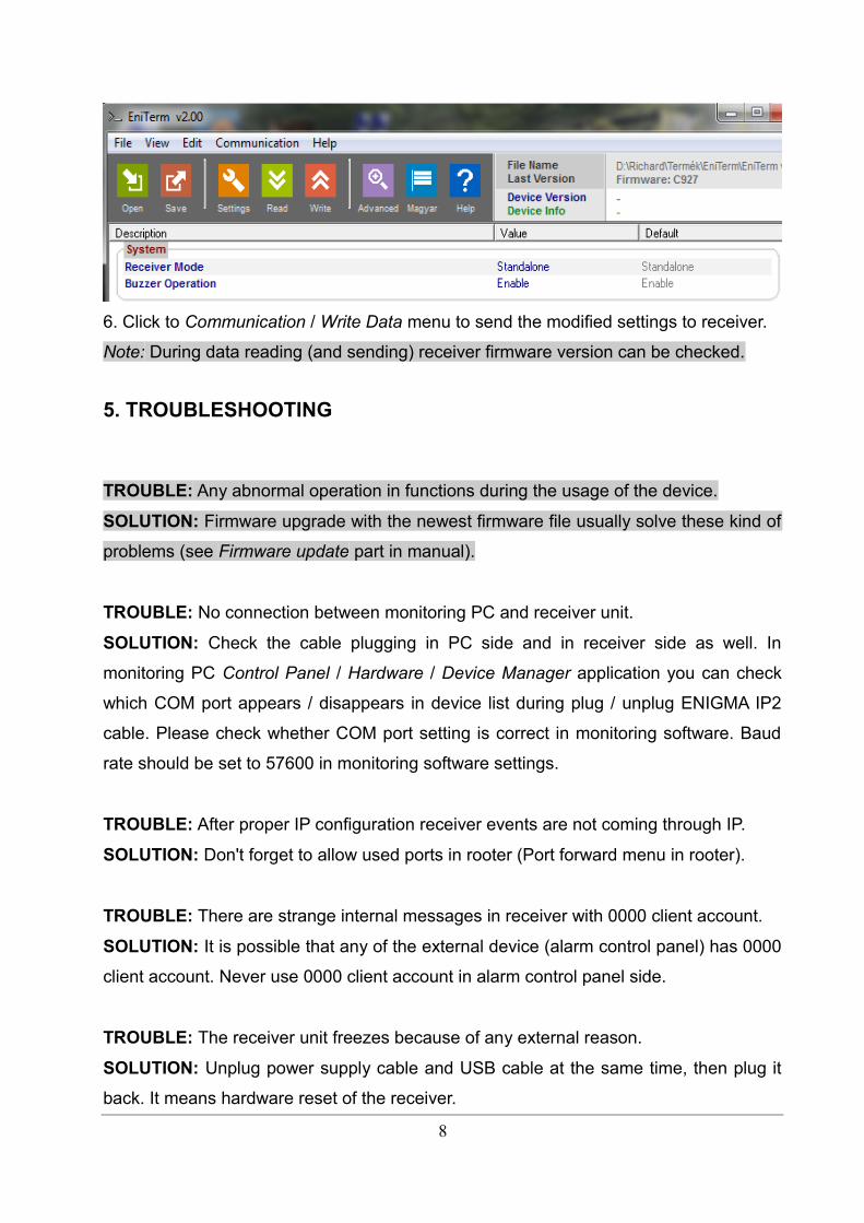
6. Click to Communication / Write Data menu to send the modified settings to receiver.
Note: During data reading (and sending) receiver firmware version can be checked.
5. TROUBLESHOOTING
TROUBLE: Any abnormal operation in functions during the usage of the device.
SOLUTION: Firmware upgrade with the newest firmware file usually solve these kind of
problems (see Firmware update part in manual).
TROUBLE: No connection between monitoring PC and receiver unit.
SOLUTION: Check the cable plugging in PC side and in receiver side as well. In
monitoring PC Control Panel / Hardware / Device Manager application you can check
which COM port appears / disappears in device list during plug / unplug ENIGMA IP2
cable. Please check whether COM port setting is correct in monitoring software. Baud
rate should be set to 57600 in monitoring software settings.
TROUBLE: After proper IP configuration receiver events are not coming through IP.
SOLUTION: Don't forget to allow used ports in rooter (Port forward menu in rooter).
TROUBLE: There are strange internal messages in receiver with 0000 client account.
SOLUTION: It is possible that any of the external device (alarm control panel) has 0000
client account. Never use 0000 client account in alarm control panel side.
TROUBLE: The receiver unit freezes because of any external reason.
SOLUTION: Unplug power supply cable and USB cable at the same time, then plug it
back. It means hardware reset of the receiver.
8
6. ENIGMA IP2 TESTING
When all setting is finished it is possible to test ENIGMA IP2 unit. Testing is also useful
to test data sending from an external installation place. The testing software in the given
local network can help a lot to check monitoring transmission and find the reason of
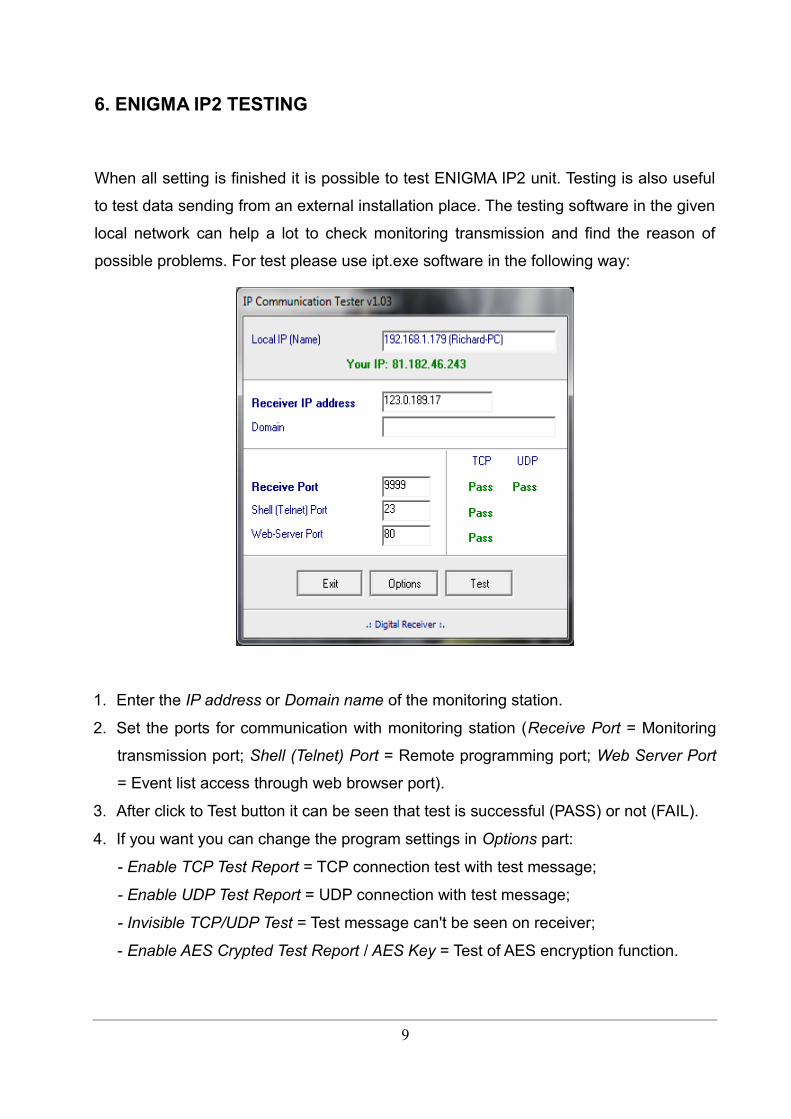
possible problems. For test please use ipt.exe software in the following way:
1. Enter the IP address or Domain name of the monitoring station.
2. Set the ports for communication with monitoring station (Receive Port = Monitoring
transmission port; Shell (Telnet) Port = Remote programming port; Web Server Port
= Event list access through web browser port).
3. After click to Test button it can be seen that test is successful (PASS) or not (FAIL).
4. If you want you can change the program settings in Options part:
- Enable TCP Test Report = TCP connection test with test message;
- Enable UDP Test Report = UDP connection with test message;
- Invisible TCP/UDP Test = Test message can't be seen on receiver;
- Enable AES Crypted Test Report / AES Key = Test of AES encryption function.
9
Received events in Enigma IP2 can be checked easily with a simple web browser
access. For this IP address (and port if it is different from 80) of Enigma IP2 unit should
be typed in a web browser (Internet Explorer recommended). Then receiver HTTP page
can be seen.
Note: For the operation of event list review through web browser the IP ADDRESS and
HTTP PORT should be enabled in rooter as well.
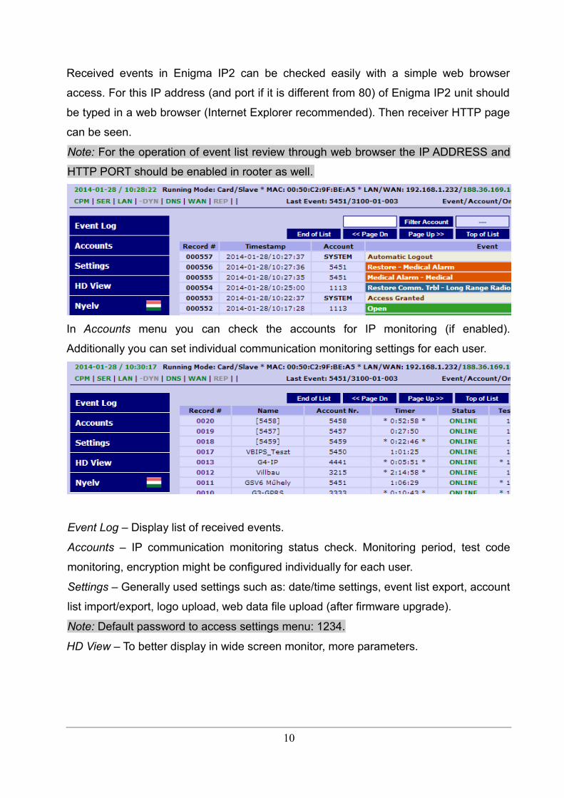
In Accounts menu you can check the accounts for IP monitoring (if enabled).
Additionally you can set individual communication monitoring settings for each user.
Event Log – Display list of received events.
Accounts – IP communication monitoring status check. Monitoring period, test code
monitoring, encryption might be configured individually for each user.
Settings – Generally used settings such as: date/time settings, event list export, account
list import/export, logo upload, web data file upload (after firmware upgrade).
Note: Default password to access settings menu: 1234.
HD View – To better display in wide screen monitor, more parameters.
10
7. FIRMWARE UPGRADE AND OTHER FUNCTIONS
It is recommended to upgrade regularly firmware of the unit to use new functions and
eliminate possible bugs.
Firmware upgrade can be done by the following steps:
1. Get the latest firmware files from your distributor (ip.ipx file).
2. Save settings from the IP card planned to update with EniTerm software (please
check 4. System programming with PC software chapter). Please close monitoring
software if it is running.
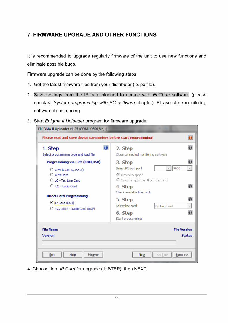
3. Start Enigma II Uploader program for firmware upgrade.
4. Choose item IP Card for upgrade (1. STEP), then NEXT.
11
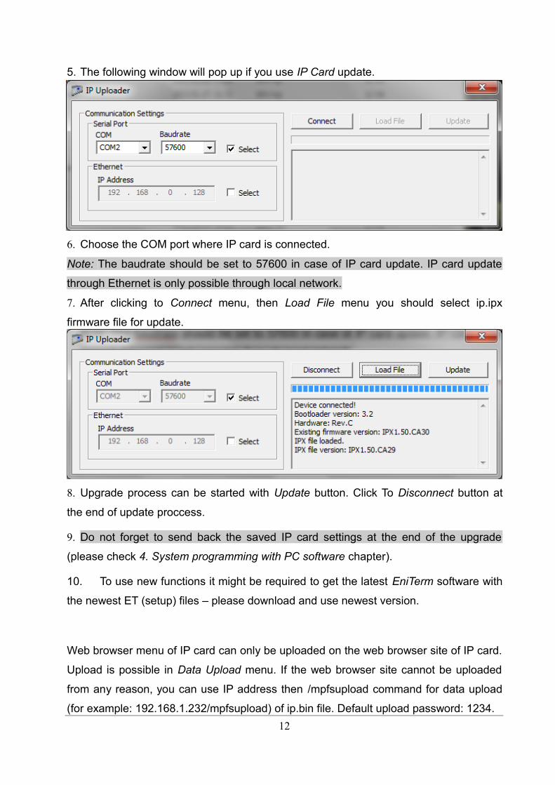
5. The following window will pop up if you use IP Card update.
6. Choose the COM port where IP card is connected.
Note: The baudrate should be set to 57600 in case of IP card update. IP card update
through Ethernet is only possible through local network.
7. After clicking to Connect menu, then Load File menu you should select ip.ipx
firmware file for update.
8. Upgrade process can be started with Update button. Click To Disconnect button at
the end of update proccess.
9. Do not forget to send back the saved IP card settings at the end of the upgrade
(please check 4. System programming with PC software chapter).
10. To use new functions it might be required to get the latest EniTerm software with
the newest ET (setup) files – please download and use newest version.
Web browser menu of IP card can only be uploaded on the web browser site of IP card.
Upload is possible in Data Upload menu. If the web browser site cannot be uploaded
from any reason, you can use IP address then /mpfsupload command for data upload
(for example: 192.168.1.232/mpfsupload) of ip.bin file. Default upload password: 1234.
12

8. SYSTEM MESSAGES
System Message Code Description
DATAFILE MODIFY B1 IP receiver card web browser data file modified
SETTING MODIFY B2 IP receiver card settings changed
PROGRAM MODE B3IP receiver card programming through serial port / IPnetwork
PROGRAM END B4IP receiver card programming through serial port / IPnetwork end
COM ERROR B5IP receiver card communication error on USB port(with monitoring software)
COM RESTORED B6IP receiver card communication restore on USB port(with monitoring software)
TCP/IP ERROR B7 IP receiver card TCP/IP network error
TCP/IP RESTORED B8 IP receiver card TCP/IP network restored
TIME/DATE SET B9 IP receiver card date and time set
FIRMWARE UPDATE B0 IP receiver card firmware updated
LAN ERROR BBIP receiver internal LAN connection (gateway) testfailed
LAN RESTORED BC IP receiver internal LAN connection (gateway) test OK
RECEIVER RESET BD IP receiver card restarted
IP WAN ERROR BE IP receiver external WAN connection test failed
IP WAN RESTORE BF IP receiver external WAN connection test OK
BATTERY ERROR 11 Receiver internal battery voltage error
BATTERY OK 12 Receiver internal battery voltage restore
RECEIVER STOP 19 Receiver shutdown before planned restart
REC. OVERHEAT 33 Receiver overheat event
IPFORW ERROR 51 Communication error in IP event forwarding
IPFORW OK 52 Communication restore in IP event forwarding
CPM COMM ERROR 53 Communication trouble with receiver CPM bus
CPM COMM OK 54 Communication restore with receiver CPM bus
IPSERVER STOP 57 IP receiving server stop in receiver
IPSERVER START 58 IP receiving server start in receiver
AC ERROR 81 AC error in receiver power supply
AC RESTORE 82 AC restore in receiver power supply
IP ERROR 1692There is no IP communication from the given clientaccount within the defined time range (comm. lost)
13

IP RESTORE 3692IP communication restored for the given clientaccount where communication was lost
Z0 The given client account was deleted on web browser
Z9 The given account was modified on web browser
Note.: System messages are sent with 0000 client account (except IP ERROR / IP
RESTORE messages, which are sent with the given client account where IP
communication was lost).
9. COMPATIBILITY
ENIGMA IP2 receiver is compatible with the following communicators and monitoring
software types:
Monitoring software
• ALARM SYS (recommended)
• SIMS
• MYMAS
SURGARD receiver should be chosen in case of SIMS, MYMAS or other monitoring
software types.
IP communicators
• VILLBAU VBIP, VBIP PRO, VBIP-G
• SECOLink LAN800
GPRS communicators
• VILLBAU VBIP-G
• SECOLink GSV2, GSV6
• SECOLink GSV3, GSV4M
• TELL ecoLINE SIA
• WM M2M Easy Communicator
• ELDES ESIM364
• ELDES ET082
14
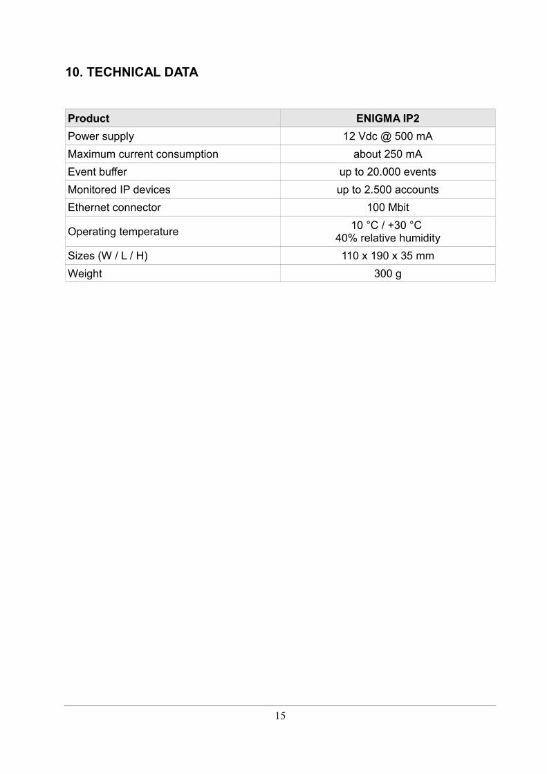
10. TECHNICAL DATA
Product ENIGMA IP2
Power supply 12 Vdc @ 500 mA
Maximum current consumption about 250 mA
Event buffer up to 20.000 events
Monitored IP devices up to 2.500 accounts
Ethernet connector 100 Mbit
Operating temperature10 °C / +30 °C
40% relative humidity
Sizes (W / L / H) 110 x 190 x 35 mm
Weight 300 g
15