Enhanced Vibrating Fork Liquid Level Switch Switch - Vibrating Fork 2130.pdf · Enhanced Vibrating...
18
Product Data Sheet February 2014 00813-0100-4130, Rev EB Rosemount 2130 Enhanced Vibrating Fork Liquid Level Switch Designed for operation in process temperatures of –94 to 500 °F (–70 to 260 °C) Electronic self-checking and condition monitoring – ‘Heartbeat’ LED gives status and instrument health information Increased safety, SIL2 certified to IEC 61508 as required by IEC 61511 Adjustable switching delay for turbulent or splashing applications “Fast drip” fork design gives quicker response time especially with viscous liquids General area, explosion-proof/flameproof, and intrinsically safe options
Transcript of Enhanced Vibrating Fork Liquid Level Switch Switch - Vibrating Fork 2130.pdf · Enhanced Vibrating...
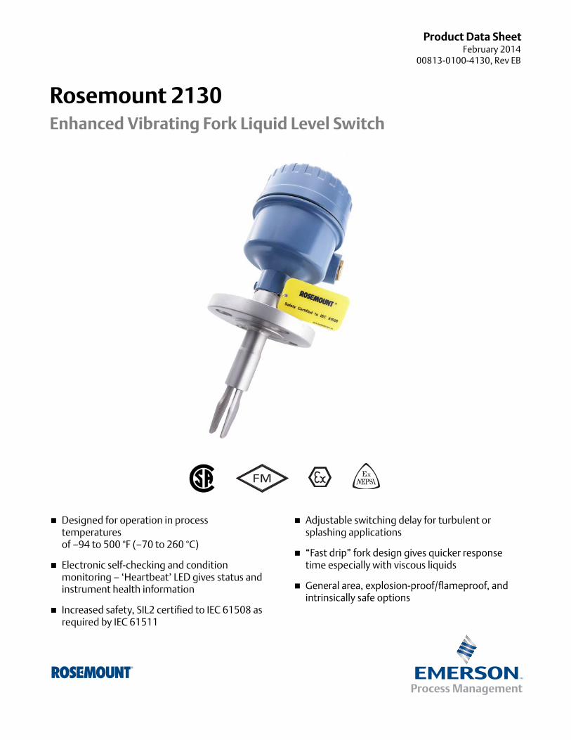
Product Data SheetFebruary 2014
00813-0100-4130, Rev EB
Rosemount 2130Enhanced Vibrating Fork Liquid Level Switch
Designed for operation in process temperaturesof –94 to 500 °F (–70 to 260 °C)
Electronic self-checking and condition monitoring – ‘Heartbeat’ LED gives status and instrument health information
Increased safety, SIL2 certified to IEC 61508 as required by IEC 61511
Adjustable switching delay for turbulent or splashing applications
“Fast drip” fork design gives quicker response time especially with viscous liquids
General area, explosion-proof/flameproof, and intrinsically safe options
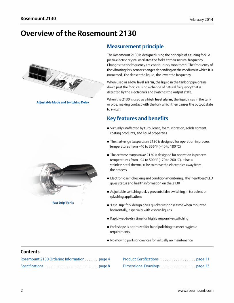
Rosemount 2130 February 2014
Overview of the Rosemount 2130
Measurement principle
The Rosemount 2130 is designed using the principle of a tuning fork. A piezo-electric crystal oscillates the forks at their natural frequency. Changes to this frequency are continuously monitored. The frequency of the vibrating fork sensor changes depending on the medium in which it is immersed. The denser the liquid, the lower the frequency.
When used as a low level alarm, the liquid in the tank or pipe drains down past the fork, causing a change of natural frequency that is detected by the electronics and switches the output state.
When the 2130 is used as a high level alarm, the liquid rises in the tank or pipe, making contact with the fork which then causes the output state to switch.
Key features and benefits
Virtually unaffected by turbulence, foam, vibration, solids content, coating products, and liquid properties
The mid-range temperature 2130 is designed for operation in process temperatures from –40 to 356 °F (–40 to 180 °C)
The extreme temperature 2130 is designed for operation in process temperatures from –94 to 500 °F (–70 to 260 °C). It has astainless steel thermal tube to move the electronics away fromthe process
Electronic self-checking and condition monitoring. The ‘heartbeat’ LED gives status and health information on the 2130
Adjustable switching delay prevents false switching in turbulent or splashing applications
‘Fast Drip’ fork design gives quicker response time when mounted horizontally, especially with viscous liquids
Rapid wet-to-dry time for highly responsive switching
Fork shape is optimized for hand polishing to meet hygienic requirements
No moving parts or crevices for virtually no maintenance
Contents
Rosemount 2130 Ordering Information . . . . . . . page 4 Product Certifications . . . . . . . . . . . . . . . . . . . . page 11
Specifications . . . . . . . . . . . . . . . . . . . . . . . . . . . . . page 8 Dimensional Drawings . . . . . . . . . . . . . . . . . . . page 13
‘Fast Drip’ Forks
Adjustable Mode and Switching Delay
2 www.rosemount.com
Rosemount 2130February 2014
Superior diagnostics
Built-in diagnostics continuously check electronic and mechanical health
Fork conditions detected including internal and external damage, coated or blocked, and extreme corrosion
Ideal for critical alarm duties
Fit and forget
Once installed, the 2130 is ready to go. It needs no calibration and requires minimum installation
The ‘heartbeat’ LED gives an instant visual indication that the unit is operational
Functional testing of the instrument and system is easy with a magnetic test point
You can install, and forget it
Extended high and low temperature performance
The extreme temperature 2130 enables standardization of Rosemount vibrating fork switches across a wide range of process environments, and is ideally suited for harsh conditions where high reliability is essential
Applications
Overfill protection
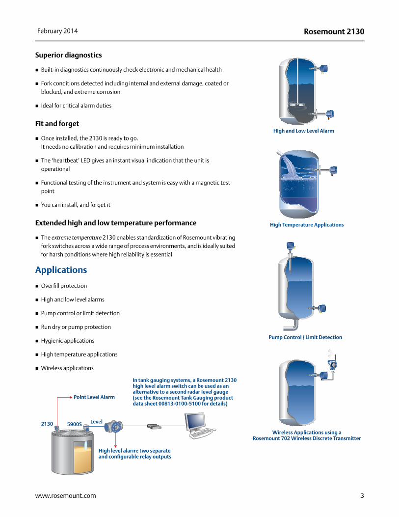
High and low level alarms
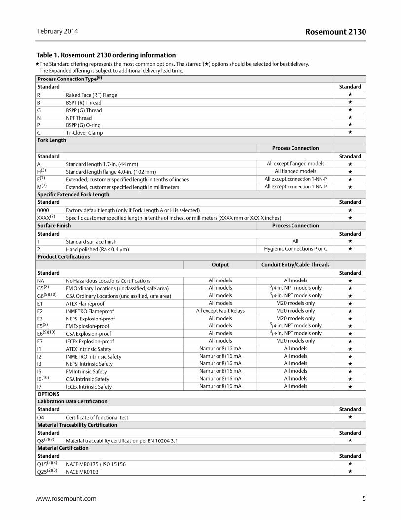
Pump control or limit detection
Run dry or pump protection
Hygienic applications
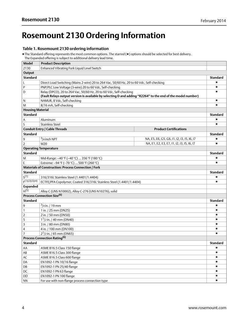
High temperature applications
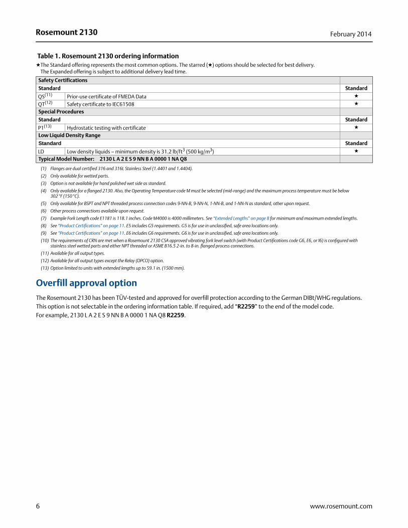
Wireless applications
High and Low Level Alarm
High Temperature Applications
Pump Control / Limit Detection
Wireless Applications using aRosemount 702 Wireless Discrete Transmitter
Rosemount TankRadar
FBM 2180
Ext
. pw
r
RS
-232
US
B
Tx Rx
Lo - GAIN - Hi On - TERM - Off
In tank gauging systems, a Rosemount 2130 high level alarm switch can be used as an alternative to a second radar level gauge (see the Rosemount Tank Gauging product data sheet 00813-0100-5100 for details)
Point Level Alarm
2130 5900S Level
High level alarm: two separate and configurable relay outputs
3www.rosemount.com
Rosemount 2130 February 2014
Rosemount 2130 Ordering Information
Table 1. Rosemount 2130 ordering information★The Standard offering represents the most common options. The starred (★) options should be selected for best delivery.
The Expanded offering is subject to additional delivery lead time.
Model Product Description
2130 Enhanced Vibrating Fork Liquid Level SwitchOutput
Standard Standard
L Direct Load Switching (Mains 2-wire) 20 to 264 Vac, 50/60 Hz, 20 to 60 Vdc, Self-checking ★
P PNP/PLC Low Voltage (3-wire) 20 to 60 Vdc, Self-checking ★
D Relay (DPCO), 20 to 264 Vac, 50/60 Hz, 20 to 60 Vdc, Self-checking(Fault Relays output version is available by selecting D and adding “R2264” to the end of the model number)
★
N NAMUR, 8 Vdc, Self-checking ★
M 8/16 mA, Self-checking ★
Housing Material
Standard Standard
A Aluminum ★
S Stainless Steel ★
Conduit Entry / Cable Threads Product Certifications
Standard Standard
9 3/4 inch NPT NA, E5, E6, G5, G6, I1, I2, I3, I5, I6, I7 ★
2 M20 NA, E1, E2, E3, E7, I1, I2, I3, I5, I6, I7 ★
Operating Temperature
Standard Standard
M Mid-Range: –40 °F (–40 °C) ... 356 °F (180 °C) ★
E Extreme: –94 °F (–70 °C) ... 500 °F (260 °C) ★
Materials of Construction: Process Connection / Fork
Standard Standard
S(1) 316/316L Stainless Steel (1.4401/1.4404) ★
F(1)(2)(3)(4) ECTFE/PFA Copolymer, Coated 316/316L Stainless Steel (1.4401/1.4404) ★
Expanded
H(5) Alloy C (UNS N10002), Alloy C-276 (UNS N10276), solidProcess Connection Size(6)
Standard Standard
9 3/4 in. / 19 mm ★
1 1 in. / 25 mm (DN25) ★
2 2 in. / 50 mm (DN50) ★
5 11/2 in. / 40 mm (DN40) ★
3 3 in. / 80 mm (DN80) ★
4 4 in. / 100 mm (DN100) ★
7 21/2 in. / 65 mm (DN65) ★
Process Connection Rating(6)
Standard Standard
AA ASME B16.5 Class 150 flange ★
AB ASME B16.5 Class 300 flange ★
AC ASME B16.5 Class 600 flange ★
DA EN1092-1 PN 10/16 flange ★
DB EN1092-1 PN 25/40 flange ★
DC EN1092-1 PN 63 flange ★
DD EN1092-1 PN 100 flange ★
NN For use with non-flange process connection type ★
4 www.rosemount.com
Rosemount 2130February 2014
Process Connection Type(6)
Standard Standard
R Raised Face (RF) Flange ★
B BSPT (R) Thread ★
G BSPP (G) Thread ★
N NPT Thread ★
P BSPP (G) O-ring ★
C Tri-Clover Clamp ★
Fork Length
Process Connection
Standard Standard
A Standard length 1.7-in. (44 mm) All except flanged models ★
H(3) Standard length flange 4.0-in. (102 mm) All flanged models ★
E(7) Extended, customer specified length in tenths of inches All except connection 1-NN-P ★
M(7) Extended, customer specified length in millimeters All except connection 1-NN-P ★
Specific Extended Fork Length
Standard Standard
0000 Factory default length (only if Fork Length A or H is selected) ★
XXXX(7) Specific customer specified length in tenths of inches, or millimeters (XXXX mm or XXX.X inches) ★
Surface Finish Process Connection
Standard Standard
1 Standard surface finish All ★
2 Hand polished (Ra < 0.4 μm) Hygienic Connections P or C ★
Product Certifications
Output Conduit Entry/Cable Threads
Standard Standard
NA No Hazardous Locations Certifications All models All models ★
G5(8) FM Ordinary Locations (unclassified, safe area) All models 3/4-in. NPT models only ★
G6(9)(10) CSA Ordinary Locations (unclassified, safe area) All models 3/4-in. NPT models only ★
E1 ATEX Flameproof All models M20 models only ★
E2 INMETRO Flameproof All except Fault Relays M20 models only ★
E3 NEPSI Explosion-proof All models M20 models only ★
E5(8) FM Explosion-proof All models 3/4-in. NPT models only ★
E6(9)(10) CSA Explosion-proof All models 3/4-in. NPT models only ★
E7 IECEx Explosion-proof All models M20 models only ★
I1 ATEX Intrinsic Safety Namur or 8/16 mA All models ★
I2 INMETRO Intrinsic Safety Namur or 8/16 mA All models ★
I3 NEPSI Intrinsic Safety Namur or 8/16 mA All models ★
I5 FM Intrinsic Safety Namur or 8/16 mA All models ★
I6(10) CSA Intrinsic Safety Namur or 8/16 mA All models ★
I7 IECEx Intrinsic Safety Namur or 8/16 mA All models ★
OPTIONSCalibration Data Certification
Standard Standard
Q4 Certificate of functional test ★
Material Traceability Certification
Standard Standard
Q8(2)(3) Material traceability certification per EN 10204 3.1 ★
Material Certification
Standard Standard
Q15(2)(3) NACE MR0175 / ISO 15156 ★
Q25(2)(3) NACE MR0103 ★
Table 1. Rosemount 2130 ordering information★The Standard offering represents the most common options. The starred (★) options should be selected for best delivery.
The Expanded offering is subject to additional delivery lead time.
5www.rosemount.com
Rosemount 2130 February 2014
Safety Certifications
Standard Standard
QS(11) Prior-use certificate of FMEDA Data ★
QT(12) Safety certificate to IEC61508 ★
Special Procedures
Standard Standard
P1(13) Hydrostatic testing with certificate ★
Low Liquid Density Range
Standard Standard
LD Low density liquids – minimum density is 31.2 lb/ft3 (500 kg/m3) ★
Typical Model Number: 2130 L A 2 E S 9 NN B A 0000 1 NA Q8
(1) Flanges are dual certified 316 and 316L Stainless Steel (1.4401 and 1.4404).
(2) Only available for wetted parts.
(3) Option is not available for hand polished wet side as standard.
(4) Only available for a flanged 2130. Also, the Operating Temperature code M must be selected (mid-range) and the maximum process temperature must be below 302 °F (150 °C).
(5) Only available for BSPT and NPT threaded process connection codes 9-NN-B, 9-NN-N, 1-NN-B, and 1-NN-N as standard, other upon request.
(6) Other process connections available upon request.
(7) Example Fork Length code E1181 is 118.1 inches. Code M4000 is 4000 millimeters. See “Extended Lengths” on page 8 for minimum and maximum extended lengths.
(8) See “Product Certifications” on page 11. E5 includes G5 requirements. G5 is for use in unclassified, safe area locations only.
(9) See “Product Certifications” on page 11. E6 includes G6 requirements. G6 is for use in unclassified, safe area locations only.
(10) The requirements of CRN are met when a Rosemount 2130 CSA approved vibrating fork level switch (with Product Certifications code G6, E6, or I6) is configured with stainless steel wetted parts and either NPT threaded or ASME B16.5 2-in. to 8-in. flanged process connections.
(11) Available for all output types.
(12) Available for all output types except the Relay (DPCO) option.
(13) Option limited to units with extended lengths up to 59.1 in. (1500 mm).
Overfill approval option
The Rosemount 2130 has been TÜV-tested and approved for overfill protection according to the German DIBt/WHG regulations.This option is not selectable in the ordering information table. If required, add “R2259” to the end of the model code.For example, 2130 L A 2 E S 9 NN B A 0000 1 NA Q8 R2259.
Table 1. Rosemount 2130 ordering information★The Standard offering represents the most common options. The starred (★) options should be selected for best delivery.
The Expanded offering is subject to additional delivery lead time.
6 www.rosemount.com
Rosemount 2130February 2014
Rosemount 2130 spare parts and accessories
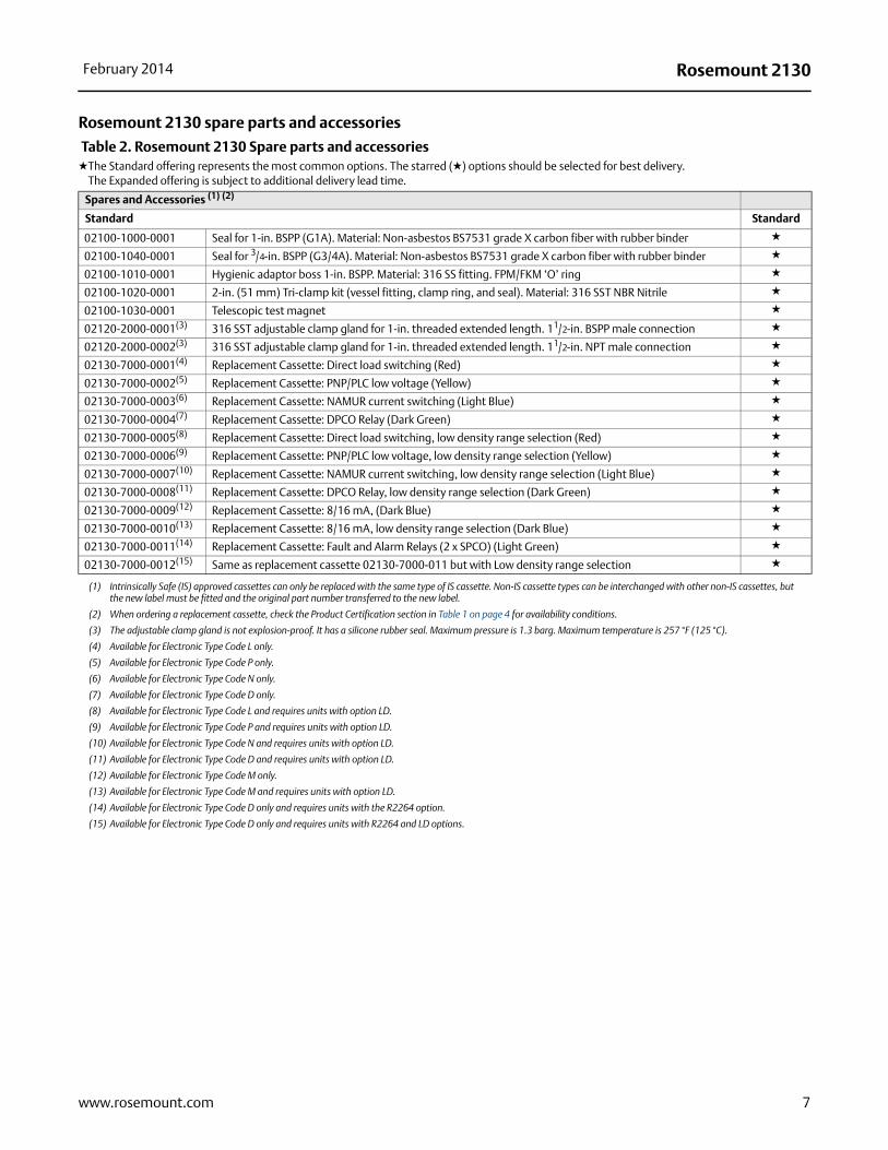
Table 2. Rosemount 2130 Spare parts and accessories★The Standard offering represents the most common options. The starred (★) options should be selected for best delivery.
The Expanded offering is subject to additional delivery lead time.
Spares and Accessories (1) (2)
(1) Intrinsically Safe (IS) approved cassettes can only be replaced with the same type of IS cassette. Non-IS cassette types can be interchanged with other non-IS cassettes, but the new label must be fitted and the original part number transferred to the new label.
(2) When ordering a replacement cassette, check the Product Certification section in Table 1 on page 4 for availability conditions.
Standard Standard
02100-1000-0001 Seal for 1-in. BSPP (G1A). Material: Non-asbestos BS7531 grade X carbon fiber with rubber binder ★
02100-1040-0001 Seal for 3/4-in. BSPP (G3/4A). Material: Non-asbestos BS7531 grade X carbon fiber with rubber binder ★
02100-1010-0001 Hygienic adaptor boss 1-in. BSPP. Material: 316 SS fitting. FPM/FKM ‘O’ ring ★
02100-1020-0001 2-in. (51 mm) Tri-clamp kit (vessel fitting, clamp ring, and seal). Material: 316 SST NBR Nitrile ★
02100-1030-0001 Telescopic test magnet ★
02120-2000-0001(3)
(3) The adjustable clamp gland is not explosion-proof. It has a silicone rubber seal. Maximum pressure is 1.3 barg. Maximum temperature is 257 °F (125 °C).
316 SST adjustable clamp gland for 1-in. threaded extended length. 11/2-in. BSPP male connection ★
02120-2000-0002(3) 316 SST adjustable clamp gland for 1-in. threaded extended length. 11/2-in. NPT male connection ★
02130-7000-0001(4)
(4) Available for Electronic Type Code L only.
Replacement Cassette: Direct load switching (Red) ★
02130-7000-0002(5)
(5) Available for Electronic Type Code P only.
Replacement Cassette: PNP/PLC low voltage (Yellow) ★
02130-7000-0003(6)
(6) Available for Electronic Type Code N only.
Replacement Cassette: NAMUR current switching (Light Blue) ★
02130-7000-0004(7)
(7) Available for Electronic Type Code D only.
Replacement Cassette: DPCO Relay (Dark Green) ★
02130-7000-0005(8)
(8) Available for Electronic Type Code L and requires units with option LD.
Replacement Cassette: Direct load switching, low density range selection (Red) ★
02130-7000-0006(9)
(9) Available for Electronic Type Code P and requires units with option LD.
Replacement Cassette: PNP/PLC low voltage, low density range selection (Yellow) ★
02130-7000-0007(10)
(10) Available for Electronic Type Code N and requires units with option LD.
Replacement Cassette: NAMUR current switching, low density range selection (Light Blue) ★
02130-7000-0008(11)
(11) Available for Electronic Type Code D and requires units with option LD.
Replacement Cassette: DPCO Relay, low density range selection (Dark Green) ★
02130-7000-0009(12)
(12) Available for Electronic Type Code M only.
Replacement Cassette: 8/16 mA, (Dark Blue) ★
02130-7000-0010(13)
(13) Available for Electronic Type Code M and requires units with option LD.
Replacement Cassette: 8/16 mA, low density range selection (Dark Blue) ★
02130-7000-0011(14)
(14) Available for Electronic Type Code D only and requires units with the R2264 option.
Replacement Cassette: Fault and Alarm Relays (2 x SPCO) (Light Green) ★
02130-7000-0012(15)
(15) Available for Electronic Type Code D only and requires units with R2264 and LD options.
Same as replacement cassette 02130-7000-011 but with Low density range selection ★
7www.rosemount.com
Rosemount 2130 February 2014
Specifications
General
Product Rosemount 2130 Enhanced Vibrating Fork Liquid Level Switch
Measuring principle Vibrating Fork
Applications Most liquids including coating liquids, aerated liquids, and slurries
Mechanical
Housing / Enclosure
Process connections Threaded, hygienic, and flanged process connections.
See Table 1 on page 4 for a complete list.
Extended Lengths The maximum extended length is 157.5 in. (4000 mm) except for
ECTFE/PFA copolymer coating and hand-polished process connection options which have a maximum length of 59.1 in. (1500 mm) and 39.4 in. (1000 mm) respectively
Process connection materials 316/316L Stainless Steel (1.4401/1.4404 dual certified)
Alloy C (UNS N10002) and Alloy C-276 (UNS N10276)– available for flanged, and BSPT and NPT threaded process connections (3/4-in. and 1-in. BSPT (R), and 3/4-in. and 1-in. NPT)
ECTFE/PFA co-polymer coated 316/316L Stainless Steel (1.4401/1.4404 dual certified) – only available for a flanged 2130
Hand-polished to better than 0.4 m option for hygienic connections
Gasket material for 3/4-in. and 1-in. BSPP (G) is non-asbestos BS7531 Grade X carbon fiber with rubber binder
Dimensional drawings See “Dimensional Drawings” on page 13
Performance
Hysteresis (water) 0.1 in. (2.5 mm)
Switching point (water) 0.5 in. (13 mm) from tip of fork (if vertical installation) or from edge
of fork (if horizontal installation) – this will vary with different liquid densities
Functional
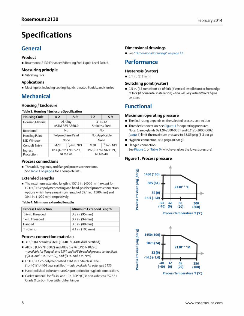
Maximum operating pressure The final rating depends on the selected process connection
Threaded connection: see Figure 1 for operating pressures.Note: Clamp glands 02120-2000-0001 and 02120-2000-0002(page 7) limit the maximum pressure to 18.85 psig (1,3 bar g)
Hygienic connection: 435 psig (30 bar g)
Flanged connection:See Figure 1 or Table 5 (whichever gives the lowest pressure)
Figure 1. Process pressure
Table 3. Housing / Enclosure Specification
Housing Code A-2 A-9 S-2 S-9
Housing Material Al Alloy ASTM B85 A360.0
316C12 Stainless Steel
Rotational No No
Housing Paint Polyurethane Paint Not Applicable
LED Window None None
Conduit Entry M20 3/4-in. NPT M20 3/4-in. NPT
Ingress Protection
IP66/67 to EN60529, NEMA 4X
IP66/67 to EN60529, NEMA 4X
Table 4. Minimum extended lengths
Process Connection Minimum Extended Length3/4–in. Threaded 3.8 in. (95 mm)
1–in. Threaded 3.7 in. (94 mm)
Flanged 3.5 in. (89 mm)
Tri-Clamp 4.1 in. (105 mm)
1450 (100)
885 (61)
-14.5 (-1.0)
-94 (-70)
68 (20)
500 (260)
Process Temperature °F (°C)
Pro
cess
Pre
ssu
re p
sig
(bar
g)
32 (0)
32 (0)
2130***E
1450 (100)
1073 (74)
-14.5 (-1.0)
-40 (-40)
68 (20)
356 (180)
Process Temperature °F (°C)
Pro
cess
Pre
ssu
re p
sig
(bar
g)
32 (0)
32 (0)
2130***M
8 www.rosemount.com
Rosemount 2130February 2014
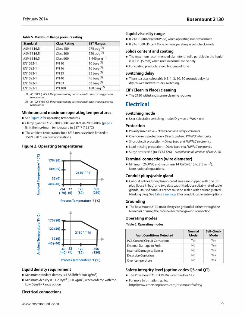
Minimum and maximum operating temperatures See Figure 2 for operating temperatures
Clamp glands 02120-2000-0001 and 02120-2000-0002 (page 7) limit the maximum temperature to 257 °F (125 °C)
The ambient temperature for a 8/16 mA cassette is limited to158 °F (70 °C) in dust applications
Figure 2. Operating temperatures
Liquid density requirement Minimum standard density is 37.5 lb/ft3 (600 kg/m3)
Minimum density is 31.2 lb/ft3 (500 kg/m3) when ordered with the Low Density Range option
Liquid viscosity range 0.2 to 10000 cP (centiPoise) when operating in Normal mode
0.2 to 1000 cP (centiPoise) when operating in Self-check mode
Solids content and coating The maximum recommended diameter of solid particles in the liquid
is 0.2 in. (5 mm) when used in normal mode only
For coating products, avoid bridging of forks
Switching delay There is a user-selectable 0.3, 1, 3, 10, 30 seconds delay for
dry-to-wet and wet-to-dry switching
CIP (Clean In Place) cleaning The 2130 withstands steam cleaning routines
Electrical
Switching mode User-selectable switching mode (Dry = on or Wet = on)
Protection Polarity insensitive – Direct Load and Relay electronics
Over-current protection – Direct Load and PNP/PLC electronics
Short-circuit protection – Direct Load and PNP/PLC electronics
Load-missing protection – Direct Load and PNP/PLC electronics
Surge protection (to IEC61326) – Available on all versions of the 2130
Terminal connection (wire diameter) Minimum 26 AWG and maximum 14 AWG (0.13 to 2.5 mm2).
Note national regulations.
Conduit plugs/cable gland Conduit entries for explosion-proof areas are shipped with one Exd
plug (loose in bag) and two dust caps fitted. Use suitably rated cable glands. Unused conduit entries must be sealed with a suitably rated blanking plug. See Table 3 on page 8 for conduit/cable entry options
Grounding The Rosemount 2130 must always be grounded either through the
terminals or using the provided external ground connection
Operating modes
Safety integrity level (option codes QS and QT) The Rosemount 2130 FMEDA is certified for SIL2.
For more information, go to: http://www.emersonprocess.com/rosemount/safety/
Electrical connections
Table 5. Maximum flange pressure rating
Standard Class/Rating SST Flanges
ASME B16.5 Class 150 275 psig (1)
(1) At 100 °F (38 °C), the pressure rating decreases with an increasing process temperature.
ASME B16.5 Class 300 720 psig (1)
ASME B16.5 Class 600 1,440 psig (1)
EN1092-1 PN 10 10 barg (2)
(2) At 122 °F (50 °C), the pressure rating decreases with an increasing process temperature.
EN1092-1 PN 16 16 barg (2)
EN1092-1 PN 25 25 barg (2)
EN1092-1 PN 40 40 barg (2)
EN1092-1 PN 63 63 barg (2)
EN1092-1 PN 100 100 barg (2)
176 (80)
176 (80)
-40 (-40)
-94 (-70)
500 (260)
Process Temperature °F (°C)
Am
bie
nt
Tem
per
atu
re °F
(°C
)
149 (65)
32 (0)
32 (0)
2130***E
176 (80)
176 (80)
-40 (-40)
-40 (-40)
356 (180)
Process Temperature °F (°C)
Am
bie
nt
Tem
per
atu
re °F
(°C
)
122 (50)
32 (0)
32 (0)
2130***M
Table 6. Operating modes
Fault Conditions DetectedNormal Mode
Self-Check Mode
PCB Control Circuit Corruption Yes Yes
External Damage to Fork No Yes
Internal Damage to Sensor No Yes
Excessive Corrosion No Yes
Over-temperature No Yes
9www.rosemount.com
Rosemount 2130 February 2014
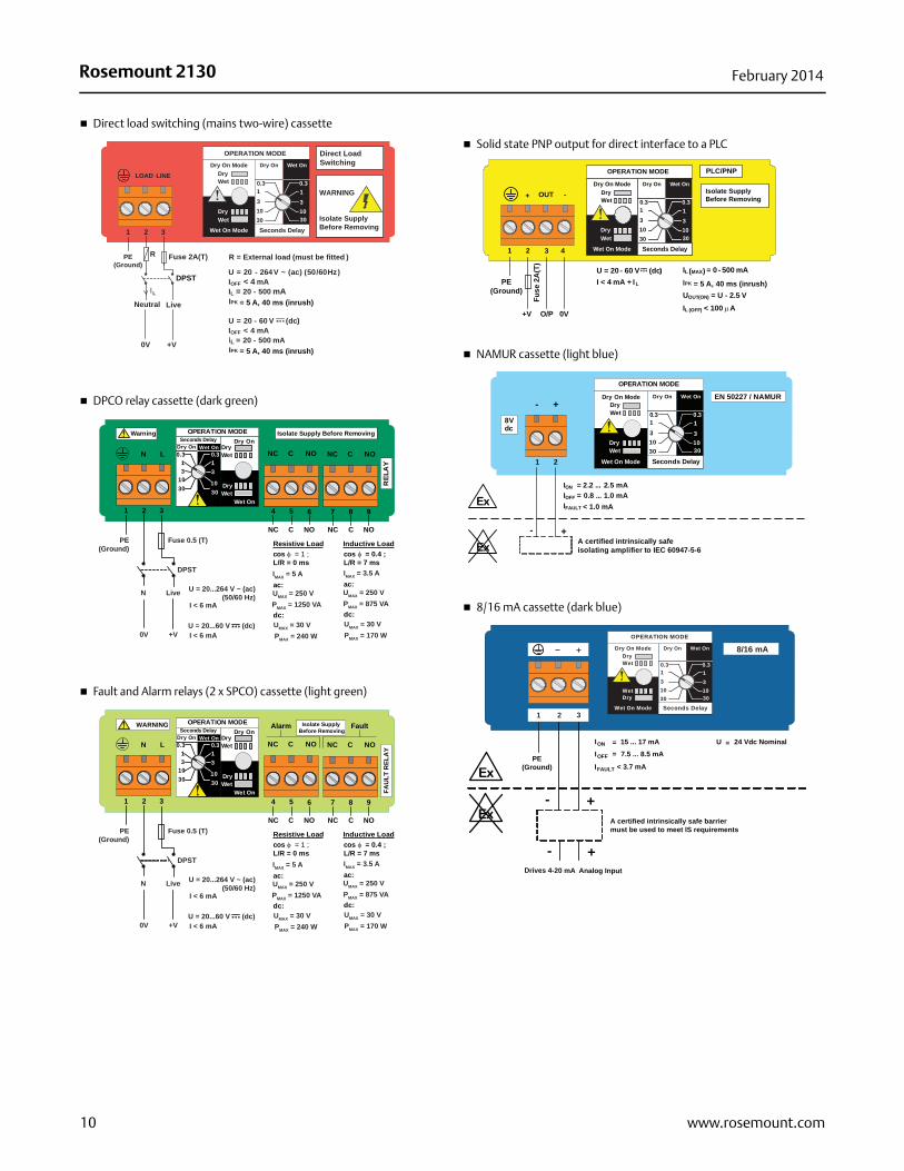
Direct load switching (mains two-wire) cassette
DPCO relay cassette (dark green)
Fault and Alarm relays (2 x SPCO) cassette (light green)
Solid state PNP output for direct interface to a PLC
NAMUR cassette (light blue)
8/16 mA cassette (dark blue)
Direct LoadSwitching
WARNING
Isolate SupplyBefore Removing
OPERATION MODEDry On Mode
DryWet
Wet On Mode
DryWet
Dry On Wet On
Seconds Delay
0.3 0.3
3
3010
1
3
3010
1
1 2 3
LINELOAD
PE(Ground)
Neutral Live
0V
Fuse 2A(T)R
IL
R = External load (must be fitted )
U = 20 - 264V ~ (ac) (50/60Hz)IOFF < 4 mAIL = 20 - 500 mA
U = 20 - 60 V (dc))IOFF < 4 mAIL = 20 - 500 mA
DPST
+V= 5 A, 40 ms (inrush)IPK
= 5 A, 40 ms (inrush)IPK
NC C NONC NO
7 8 9
NOCNC
REL
AY
1 2 3
LN
4 5 6
NOCNC
OPERATION MODEDry On
DryWet
Wet On
DryWet
Dry On Wet OnSeconds Delay
3010
31
0.3 0.3
3010
31
Isolate Supply Before Removing Warning
C
Resistive Loadcos φ = 1 ;L/R = 0 ms
ac:
dc:
Inductive LoadFuse 0.5 (T)PE(Ground)
DPST
N
0V +V
Live U = 20...264 V ~ (ac) (50/60 Hz)
U = 20...60 V (dc)
I < 6 mA
I < 6 mA
IMAX = 5 A
UMAX = 250 VPMAX = 1250 VA
UMAX = 30 VPMAX = 240 W
cos φ = 0.4 ;L/R = 7 ms
ac:
dc:
IMAX = 3.5 A
UMAX = 250 VPMAX = 875 VA
UMAX = 30 VPMAX = 170 W
NC C NONC NO
7 8 9
NOCNC
1 2 3
LN
4 5 6
NOCNC
Alarm FaultOPERATION MODEDry On
DryWet
Wet On
DryWet
Dry On Wet OnSeconds Delay
3010
31
0.3 0.3
3010
31
Isolate Supply Before Removing
WARNING
C
Resistive Loadcos φ = 1 ;L/R = 0 ms
ac:
dc:
Inductive LoadFuse 0.5 (T)PE(Ground)
DPST
N
0V +V
Live U = 20...264 V ~ (ac) (50/60 Hz)
U = 20...60 V (dc)
I < 6 mA
I < 6 mA
IMAX = 5 A
UMAX = 250 VPMAX = 1250 VA
UMAX = 30 VPMAX = 240 W
cos φ = 0.4 ;L/R = 7 ms
ac:
dc:
IMAX = 3.5 A
UMAX = 250 VPMAX = 875 VA
UMAX = 30 VPMAX = 170 W
FAU
LT R
ELA
Y
OPERATION MODE
Dry On ModeDryWet
Wet On Mode
DryWet
Dry On Wet On
Seconds Delay
0.3 0.3
3
3010
1
3
3010
1
1 2 3
OUT+ -
4
PLC/PNP
Isolate SupplyBefore Removing
PE(Ground)
0VO/P
U = 20 - 60 V (dc)I < 4 mA + IL
IL (MAX) = 0 - 500 mA
UOUT(ON) = U - 2.5 VIL (OFF) < 100A
+V
Fuse
2A
(T)
= 5 A, 40 ms (inrush)IPK
OPERATION MODE
Dry On ModeDryWet
Wet On Mode
DryWet
Dry On Wet On
Seconds Delay
0.3 0.3
3
3010
1
3
3010
1
1 2
+-EN 50227 / NAMUR
ION = 2.2 ... 2.5 mAIOFF
IFAULT
= 0.8 ... 1.0 mA
+-A certified intrinsically safe isolating amplifier to IEC 60947-5-6
Ex
Ex
8Vdc
< 1.0 mA
OPERATION MODE
Dry On ModeDryWet
Wet On Mode
DryWet
Dry On Wet On
Seconds Delay
0.3 0.3
3
3010
1
3
3010
1
8/16 mA
1 2 3
+
Drives 4-20 mA Analog Input
ION = IOFF =
+-
+
A certified intrinsically safe barriermust be used to meet IS requirements
Ex
Ex
15 ... 17 mA7.5 ... 8.5 mA
-
PE(Ground)
U = 24 Vdc Nominal
IFAULT < 3.7 mA
10 www.rosemount.com
Rosemount 2130February 2014
Product Certifications
European directive information
The EC declaration of conformity for all applicable European directives for this product can be found on the Rosemount website at www.rosemount.com.
ATEX Directive (94/9/EC)
Complies with the ATEX Directive.
Pressure Equipment Directive (PED) (97/23/EC)
The Rosemount 2130 is outside the scope of PED Directive.
L.V. Directive
EN61010-1 Pollution degree 2, Category II (264V max),Pollution degree 2, Category III (150V max)
Electro Magnetic Compatibility (EMC) Directive
EN61326 Emissions to Class B. Immunity to industrial location requirements.NAMUR NE21.
CE-mark
Complies with applicable directives (EMC, ATEX, LVD).
NAMUR approval
NAMUR NE95 type test report is available upon request. Complies with NAMUR NE21.
Overfill approval
Certificate number: Z-65.11-519.TÜV-tested and approved for overfill protection according to the German DIBt/WHG regulations.
This option is not selectable in the ordering information table.If required, add “R2259” to the end of the model code.For example, 2130 L A 2 E S 9 NN B A 0000 1 NA Q8 R2259.
Marine approvals
ABS American Bureau of ShippingGL Germanischer Lloyd (excludes Alarm and Fault relays)
Drinking water approval
Mobrey Ltd. (Slough, United Kingdom) confirms that the wetted parts of the Rosemount 2130 vibrating fork level switch are suitable and approved for drinking water usage.
The wetted parts of the vibrating fork level switches executed in stainless steel (option code S) and Alloy C/Alloy C-276 (option code H). These materials are toxicological and microbiological classified as safe and in accordance with DIN 50930-6.
Ordinary location certification for FM
G5 Project ID: 3021776The switch has been examined and tested to determine that the design meets basic electrical, mechanical, and fire protection requirements by FM, a nationally recognized testing laboratory (NRTL) as accredited by the Federal Occupational Safety and Health Administration (OSHA).
Ordinary location certification for CSA
G6 Certificate Number: 06 CSA 1805769The switch has been examined and tested to determine that the design meets basic electrical, mechanical, and fire protection requirements by CSA, a nationally recognized testing laboratory as accredited by the Standards Council of Canada (SCC).
Single Seal
Canadian Registration Number
CRN 0F04227.2C
NOTEThe requirements of CRN are met when a Rosemount 2130 CSA-approved (G6, E6, or I6 codes) vibrating fork level switch is configured with 316/316L stainless steel (1.4401/1.4404) wetted parts and either NPT threaded or 2-in. to 8-in. ASME B16.5 flanged process connections.
Hazardous locations certifications
North American approvals
Factory Mutual (FM) explosion-proof approval
E5 Project ID: 3012658Explosion-proof for Class I, Div. 1, Groups A, B, C, and DTemperature Class: T6 (Tamb –50 to +75 °C)Enclosure: Type 4X
11www.rosemount.com
Rosemount 2130 February 2014
Factory Mutual (FM)intrinsically safe approval and non-incendive approvals
I5 Project ID: 3011456Intrinsically Safe for Class I, Div. 1, Groups A, B, C, and DClass I, Zone 0, AEx ia IICNon-incendive for Class I, Div. 2, Groups A, B, C, and DClass I, Zone 2, IICTemperature Code: T5 (Tamb –40 to 80 °C, Tproc < 80 °C)Control Drawing: 71097/1154 (with NAMUR electronics)Control Drawing: 71097/1314 (with 8/16 mA electronics)
NOTEA certified isolating amplifier or barrier must be used for intrinsic safety.
Canadian approvals
Canadian Standards Association (CSA) explosion-proof
E6 Project ID: 1786345Explosion-proof for Class I, Div. 1, Groups A, B, C, and DTemperature Class: T6 (Tamb –50 to +75 °C)Enclosure: Type 4XSingle Seal
Canadian Standards Association (CSA)intrinsically safe and non-incendive approvals
I6 Certificate Number: 06 CSA 1786345Intrinsically Safe for Class I, Div. 1, Groups A, B, C, and DClass 1, Zone 0, Ex ia IICNon-incendive for Class I, Div. 2, Groups A, B, C, and DTemperature Code: T5 (Tamb –50 to +80 °C, Tproc < 80 °C)Control Drawing: 71097/1179 (with NAMUR electronics)Control Drawing: 71097/1315 (with 8/16 mA electronics)Single Seal
NOTEA certified isolating amplifier or barrier must be used for intrinsic safety.
European approvals
ATEX flameproof and dust proof approval
E1 Certificate: Sira 05ATEX1129XFlameproof and dust proof: ATEX Marking II 1/2 G DEx d IIC T6...T2 Ga/GbEx tb IIIC T85 °C...T265 °C Db
ATEX intrinsically safe approval
I1 Certificate: Sira 05ATEX2130XIntrinsic Safety for gas and dust atmospheres: ATEX Marking II 1 G DEx ia IIC T5...T2 GaEx ia IIIC T85 °C...T265 °C Da
NOTEA certified isolating amplifier or barrier must be used for intrinsic safety.
International approvals
INMETRO flameproof and dust proof approval
E2 Certificate Number: TÜV 12.1285 XFlameproof and dust proof:Ex d IIC T6 to T2 Ga/Gb, Ex tb IIIC T85 °C to T265 °C Db
INMETRO intrinsically safe approval
I2 Certificate Number: TÜV 12.1391 XIntrinsically Safe for gas and dust atmospheres:Ex ia IIC T* Ga, Ex ia IIIC T* Da (* See table in the certificate)Ta* (* See table in the certificate)
NOTEA certified isolating amplifier or barrier must be used for intrinsic safety.
National Supervision and Inspection Centre for Explosion Protection and Safety Instrumentation (NEPSI)flameproof and dust proof approval
E3 Certificate Number: GYJ101373Flameproof and dust proof:Ex d IIC T6 to T2DIP A21 TA (T85°C to 265°C) IP6X
National Supervision and Inspection Centre for Explosion Protection and Safety Instrumentation (NEPSI)intrinsically safe approval
I3 Certificate Number: GYJ101372X (NAMUR electronics only)Intrinsic Safety:Ex ia IIC T5 to T2
NOTEA certified isolating amplifier or barrier must be used for intrinsic safety.
International Electrotechnical Commission (IEC)flameproof and dust proof approval
E7 Certificate: IECEx SIR 06.0051XFlameproof and dust proof:Ex d IIC T6...T2 Ga/GbEx tb IIIC T85 °C...T265 °C Db
International Electrotechnical Commission (IEC)intrinsically safe approval
I7 Certificate: IECEx SIR 06.0070XIntrinsically Safe for gas and dust atmospheres: Ex ia IIC T5...T2 GaEx ia IIIC T85 °C...T265 °C Da
12 www.rosemount.com

Rosemount 2130February 2014
Dimensional Drawings
Thread mounting (standard length) . . . . . . . . . . . . . . . . . . . . . . . . . . . . . . . . . . . . . . . . . . . . . . . . . . . page 13
Thread mounting (extended length) . . . . . . . . . . . . . . . . . . . . . . . . . . . . . . . . . . . . . . . . . . . . . . . . . . page 14
Flange mounting (standard length) . . . . . . . . . . . . . . . . . . . . . . . . . . . . . . . . . . . . . . . . . . . . . . . . . . . page 15
Flange mounting (extended length) . . . . . . . . . . . . . . . . . . . . . . . . . . . . . . . . . . . . . . . . . . . . . . . . . . . page 16
Thread mounting (standard length)
A. Aluminum or SST Housing
B. Cable Entry M20x1.5 or 3/4-in. NPT
C. 1.575 (40) A/F Hexagon
D. 3/4-in. or 1-in. Thread
A
0.5 (13)Switchpoint (When
Mounted Horizontally)
0.5 (13)Switchpoint (When Mounted Vertically)
13.7(348)
4.7 (120)
1.7(44)
B
Note: Dimensions are in inches (millimeters)
2.8(70)
Allow 1.2 (30)To Remove Lid
2130***E 2130***M
Allow 1.2 (30)To Remove Lid
4.7 (120)
7.1(182)
2.7(69) 1.7
(44)
0.5 (13)Switchpoint (When Mounted Vertically)
0.5 (13)Switchpoint (When
Mounted Horizontally)
AB
C
D
NOTE: FOR HYGIENIC 2130 DIMENSIONS, SEE TYPE 1 DRAWING DOWNLOADS ON WEB SITE
C
D
13www.rosemount.com
Rosemount 2130 February 2014
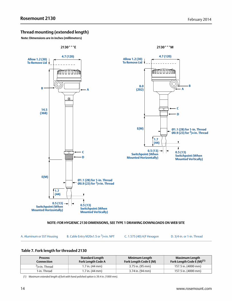
Thread mounting (extended length)
A. Aluminum or SST Housing B. Cable Entry M20x1.5 or 3/4-in. NPT C. 1.575 (40) A/F Hexagon D. 3/4-in. or 1-in. Thread
Table 7. Fork length for threaded 2130
ProcessConnection
Standard LengthFork Length Code A
Minimum LengthFork Length Code E (M)
Maximum Length Fork Length Code E (M)(1)
(1) Maximum extended length of fork with hand-polished option is 39.4 in. (1000 mm).
3/4-in. Thread 1.7 in. (44 mm) 3.75 in. (95 mm) 157.5 in. (4000 mm)
1-in. Thread 1.7 in. (44 mm) 3.74 in. (94 mm) 157.5 in. (4000 mm)
A
D
E(M)
1.7(44)
B
Note: Dimensions are in inches (millimeters)
0.5 (13)Switchpoint (When
Mounted Horizontally)
0.5 (13)Switchpoint (When Mounted Vertically)
14.5(368)
4.7 (120)Allow 1.2 (30)To Remove Lid
Ø1.1 (28) for 1-in. ThreadØ0.9 (23) for 3/4-in. Thread
2130***E
4.7 (120)
AB
Allow 1.2 (30)To Remove Lid
8.0(202)
C
D
Ø1.1 (28) for 1-in. ThreadØ0.9 (23) for 3/4-in. Thread
0.5 (13)Switchpoint (When Mounted Vertically)
0.5 (13)Switchpoint (When
Mounted Horizontally)
1.7(44)
2130***M
E(M)
C
NOTE: FOR HYGIENIC 2130 DIMENSIONS, SEE TYPE 1 DRAWING DOWNLOADS ON WEB SITE
14 www.rosemount.com
Rosemount 2130February 2014
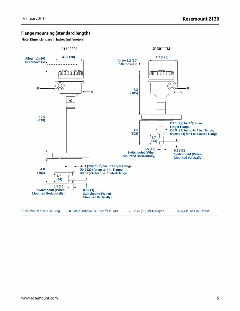
Flange mounting (standard length)
A. Aluminum or SST Housing B. Cable Entry M20x1.5 or 3/4-in. NPT C. 1.575 (40) A/F Hexagon D. 3/4-in. or 1-in. Thread
Note: Dimensions are in inches (millimeters)
A
12.9(328)
B
1.7(44)
4.0(102)
0.5 (13)Switchpoint (When
Mounted Horizontally)
Ø1.1 (28) for 11/2 in. or Larger Flange;Ø0.9 (23) for up to 1 in. Flange;Ø0.95 (24) for 1 in. Coated Flange
0.5 (13)Switchpoint (When Mounted Vertically)
4.7 (120)Allow 1.2 (30)To Remove Lid
2130***E 2130***M
4.7 (120)
AB
Allow 1.2 (30)To Remove Lid
7.3(185)
4.0(102)
1.7(44)
0.5 (13)Switchpoint (When
Mounted Horizontally)
0.5 (13)Switchpoint (When Mounted Vertically)
Ø1.1 (28) for 11/2 in. orLarger Flange;Ø0.9 (23) for up to 1 in. Flange;Ø0.95 (24) for 1 in. Coated Flange
15www.rosemount.com
Rosemount 2130 February 2014
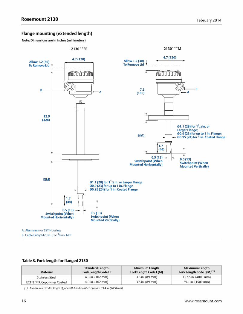
Flange mounting (extended length)
A. Aluminum or SST Housing
B. Cable Entry M20x1.5 or 3/4-in. NPT
Table 8. Fork length for flanged 2130
MaterialStandard Length
Fork Length Code HMinimum Length
Fork Length Code E(M)Maximum Length
Fork Length Code E(M)(1)
(1) Maximum extended length of fork with hand-polished option is 39.4 in. (1000 mm).
Stainless Steel 4.0-in. (102 mm) 3.5 in. (89 mm) 157.5 in. (4000 mm)
ECTFE/PFA Copolymer Coated 4.0-in. (102 mm) 3.5 in. (89 mm) 59.1 in. (1500 mm)
Note: Dimensions are in inches (millimeters)
AB
1.7(44)
12.9(328)
E(M)
0.5 (13)Switchpoint (When
Mounted Horizontally)
Ø1.1 (28) for 11/2 in. or Larger FlangeØ0.9 (23) for up to 1 in. FlangeØ0.95 (24) for 1 in. Coated Flange
0.5 (13)Switchpoint (When Mounted Vertically)
4.7 (120)Allow 1.2 (30)To Remove Lid
4.7 (120)
AB
Allow 1.2 (30)To Remove Lid
0.5 (13)Switchpoint (When
Mounted Horizontally)
0.5 (13)Switchpoint (When Mounted Vertically)
Ø1.1 (28) for 11/2 in. orLarger Flange;Ø0.9 (23) for up to 1 in. Flange;Ø0.95 (24) for 1 in. Coated FlangeE(M)
7.3(185)
2130***E 2130***M
1.7(44)
16 www.rosemount.com

Rosemount 2130February 2014
17www.rosemount.com
Rosemount 213000813-0100-4130, Rev EB
Product Data SheetFebruary 2014
Emerson Process ManagementRosemount Inc.8200 Market BoulevardChanhassen, MN 55317 USAT (USA) 1 800 999 9307T (International) +1 952 906 8888F +1 952 906 8889www.rosemount.com
Emerson Process ManagementNeuhofstrasse 19aCH 6341 BaarSwitzerlandT +41 (0) 41 768 61 11F +41 (0) 41 76 1 87 40www.rosemount.com
Emerson Process ManagementEmerson Process Management
Standard Terms and Conditions of Sale can be found at www.rosemount.com\terms_of_saleThe Emerson logo is a trade mark and service mark of Emerson Electric Co.Rosemount and the Rosemount logotype are registered trademarks of Rosemount Inc.PlantWeb is a registered trademark of one of the Emerson Process Management group of companies.HART and WirelessHART are registered trademarks of the HART Communication FoundationAll other marks are the property of their respective owners.© 2014 Rosemount Inc. All rights reserved.
Latin America1300 Concord Terrace, Suite 400Sunrise Florida 33323 USAT + 1 954 846 5030www.rosemount.com
Asia Pacific Pte Ltd1 Pandan CrescentSignapore 128461T +65 6777 8211F +65 6777 0947Service Support Hotline: +65 6770 8711Email: [email protected]