ENGS 116 Lecture 191 Interconnection Networks Vincent H. Berk November 24, 2008 Reading for today:...
48
ENGS 116 Lecture 19 1 Interconnection Networks Vincent H. Berk November 24, 2008 Reading for today: Sections 6.1 – 6.4 Reading for Monday: Sections 6.5 – 6.9
-
date post
21-Dec-2015 -
Category
Documents
-
view
213 -
download
0
Transcript of ENGS 116 Lecture 191 Interconnection Networks Vincent H. Berk November 24, 2008 Reading for today:...

ENGS 116 Lecture 19 1
Interconnection Networks
Vincent H. Berk
November 24, 2008
Reading for today: Sections 6.1 – 6.4
Reading for Monday: Sections 6.5 – 6.9

ENGS 116 Lecture 19 2
Project Reports
• Due by Beginning of class on Monday, December 1st
• Content
– Introduction and description of the topic
– Coverage of topic: breadth/depth, appropriate background information
– Analysis and discussion
– References: correct citations, proper form
• Writing
– Spelling
– Grammar
– Style and presentation
• Assume that the reader is familiar with basic architecture concepts
• Must use appropriate citations.
• Argument all your decisions.
• Email all source code to <[email protected]>
ENGS 116 Lecture 19 3
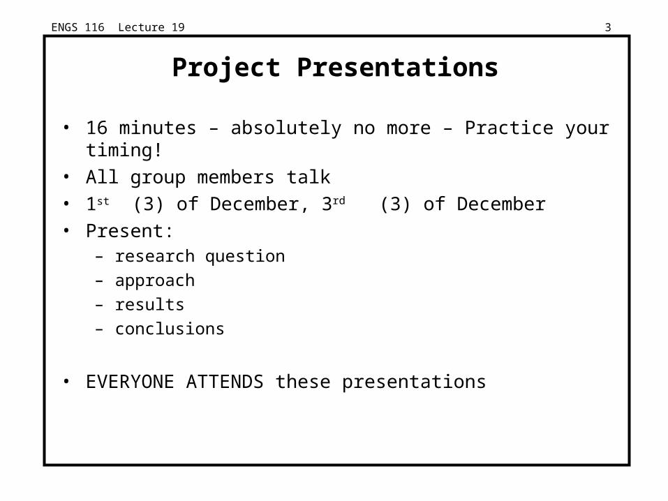
Project Presentations
• 16 minutes – absolutely no more – Practice your timing!
• All group members talk
• 1st (3) of December, 3rd (3) of December
• Present:– research question
– approach
– results
– conclusions
• EVERYONE ATTENDS these presentations

General Announcement
• Hardware Security Project starting this Winter term
• Design and implementation of Hardware Based Profiler
• Need: 1 or 2 Masters or PhD students
• Contact: Steve Taylor or Vincent Berk

ENGS 116 Lecture 19 5
Networks
• Common topics of conversation:– direct (point-to-point) vs. indirect (multi-hop)– topology (e.g., bus, ring, directed acyclic graph, star)– routing algorithms– switching (aka multiplexing)– wiring (e.g., choice of media, copper, coax, fiber)
• What really matters:– latency– bandwidth– cost– reliability

ENGS 116 Lecture 19 6
ABCs of Networks
• Starting point: Send bits between 2 computers
• Queue on each end
• Can send both ways (“Full Duplex”)
• Rules for communication? “protocol”
– Inside a computer:
• Loads/Stores: Request (Address) & Response (Data)
• Need request & response signaling
– Name for standard group of bits sent: packet

ENGS 116 Lecture 19 7
A Simple Example
• What is the format of a packet? (Protocol)
– Fixed? Number of bytes?
Request/Response
Address/Data
1 bit 32 bits
0: Please send data from address1: Packet contains data corresponding to request

ENGS 116 Lecture 19 8
Questions About Simple Example
• What if more than 2 computers want to communicate?
– Need computer address field (destination) in packet
• What if packet is garbled in transit?
– Add error detection field in packet (e.g., CRC)
• What if packet is lost?
– More elaborate protocols to detect loss (e.g., NAK, ARQ, time outs)
• What if multiple processes per machine?
– Queue per process
• Questions such as these lead to more complex protocols and packet formats

ENGS 116 Lecture 19 9
A Simple Example Revisited
• What is the format of a packet?
– Fixed? Number of bytes?
Request/Response
Address/Data
2 bits 32 bits
00: Request—Please send data from address01: Reply—Packet contains data corresponding to request10: Acknowledge request11: Acknowledge reply
4 bits
CRC

ENGS 116 Lecture 19 10
Additional Background
• Connection of 2 or more networks: Internetworking
• 3 cultures for 3 classes of networks
– SAN: server (storage) networks, performance
– LAN: workstations, cost
– WAN: telecommunications, long range
• Cost
• Performance (BW, latency)
• Reliability

ENGS 116 Lecture 19 11
Interconnections (Networks)• Examples:
– SAN networks (infiniband): 100s nodes; ≤ 10 meters per link– Local Area Networks (Ethernet): 100s nodes; ≤ 100 meters– Wide Area Network (ATM): 1000s nodes; ≤ 5,000,000 meters
Interconnect
SW Interface
HW Interface
Node
Link
SW Interface
HW Interface
Node
Link
SW Interface
HW Interface
Node
Link
SW Interface
HW Interface
Node
Link...
...

ENGS 116 Lecture 19 12
Software to Send and Receive
• SW Send steps
1: Application copies data to OS buffer
2: OS calculates checksum, starts timer
3: OS sends data to network interface HW and says start
• SW Receive steps
3: OS copies data from network interface HW to OS buffer
2: OS calculates checksum, if matches send ACK; if not, deletes message (sender resends when timer expires)
1: If OK, OS copies data to user address space and signals application to continue
• Sequence of steps for SW: protocol
– Example similar to UDP/IP protocol in UNIX

ENGS 116 Lecture 19 13
Network Performance Measures
SW Interface
HW Interface
Node
LinkBandwidth
Overhead
Link
SW Interface
HW Interface
Node
LinkBandwidth
Overhead
Link
Bisection Bandwidth
Interconnect
Latency
...
...

ENGS 116 Lecture 19 14
Universal Performance Metrics
Sender
Receiver
SenderOverhead
Transmission time(size ÷ bandwidth)
Transmission time(size ÷ bandwidth)
Time ofFlight
ReceiverOverhead
Transport Latency
Total Latency = Sender Overhead + Time of Flight + Message Size ÷ BW + Receiver Overhead
Includes header/trailer in BW calculation?
Total Latency
(processorbusy)
(processorbusy)

ENGS 116 Lecture 19 15
Simplified Latency Model
• Total Latency ≈ Overhead + Message Size / BW
• Overhead = Sender Overhead + Time of Flight + Receiver Overhead
• Example: show what happens as we vary the following
– Overhead: 1, 25, 500 µsec
– BW: 10, 100, 1000 Mbit/sec (factors of 10)
– Message Size: 16 Bytes to 4 MB (factors of 4)
• If overhead is 500 µsec, how big a message is needed to get > 10 Mb/s of bandwidth?

ENGS 116 Lecture 19 16
0.01
0.1
1
10
100
1000
16 64 256
1024
4096
16384
65536
262144
10485764194304
Message Size (bytes)
Eff
ecti
ve B
an
dw
idth
(M
bit
s/s
ec)
o1, bw10
o1, bw100
o1, bw1000
o25, bw10
o25, bw100
o25, bw1000
o500, bw10
o500, bw100
o500, bw1000
o1, bw1000
o500, bw1000o25, bw1000
o500, bw100
o500, bw10
bw1000
bw100
bw10
o1, bw100
Overhead, Bandwidth, Size

ENGS 116 Lecture 19 17
Measurement: Sizes of Message for NFS
• 95% messages, 30% bytes for packets ≤ 200 bytes• > 50% data transferred in packets = 8KB
Packet size
Cu
mu
lati
ve %
0%
10%
20%
30%
40%
50%
60%
70%
80%
90%
100%
0 1024 2048 3072 4096 5120 6144 7168 8192
Msgs
Bytes Why?

ENGS 116 Lecture 19 18
HW Interface Issues• Where to connect network to computer?
– Cache consistent to avoid flushes? ( memory bus)
– Latency and bandwidth? ( memory bus)
– Standard interface card? ( I/O bus)
– MPP memory bus; LAN, WAN I/O bus
$
CPU
L2 $
Memory Bus
Memory Bus Adaptor
I/O bus
I/OController
I/OController
Network
ideal: high bandwidth, low latency, standard interface
Network

ENGS 116 Lecture 19 19
SW Interface Issues
• How to connect network to software?
– Programmed I/O? (low latency)
– DMA? (best for large messages)
– Receiver interrupted or received polls?
• Things to avoid
– Invoking operating system in common case
– Operating at uncached memory speed (e.g., check status of network interface)

ENGS 116 Lecture 19 20
CM-5 Software Interface
• CM-5 example (MPP)– Time per poll 1.6 secs; time
per interrupt 19 secs
– Minimum time to handle message: 0.5 secs
– Enable/disable 4.9/3.8 secs
• As rate of messages arriving changes, use polling or interrupt?
– Solution: Always enable interrupts, have interrupt routine poll until no messages pending
– Low arrival rate interrupt
– High arrival rate polling
0
10
20
30
40
50
60
70
80
90
100
0 10 20 30 40 50 60 70 80 90 100
message interarrival (µsecs)
mes
sage
ove
rhea
d (µ
secs
)
Polling
Interrupts
Time between messages
Overhead

ENGS 116 Lecture 19 21
Network Media
Copper, 1mm thick, twisted to avoidantenna effect (telephone)
Used by cable companies: high BW, good noise immunity
3 parts are cable, light source, light detector.
Twisted Pair:
Coaxial Cable:
Copper coreInsulator
Braided outer conductorPlastic Covering
Fiber Optics
Transmitter– L.E.D– Laser Diode
Receiver– Photodiode
lightsource Silica
Total internalreflectionAir

ENGS 116 Lecture 19 22
Connecting Multiple Computers
• Shared Media vs. Switched: pairs communicate at same time, “point-to-point” connections
• Aggregate BW in switched network is many times that of shared
– point-to-point faster since no arbitration, simpler interface
• Arbitration in shared network?– Central arbiter for LAN?
– Listen to check if being used (“Carrier Sensing”)
– Listen to check if collision (“Collision Detection”)
– Random resend to avoid repeated collisions; not fair arbitration;
– OK if low utilization
(a.k.a. data switching interchanges, multistageinterconnection networks,interface message processors)
Switch
NodeNode
Node Node
Switched Media (CM-5, Fast-Ethernet)
Node Node Node
Shared Media (Ethernet)
ENGS 116 Lecture 19 23
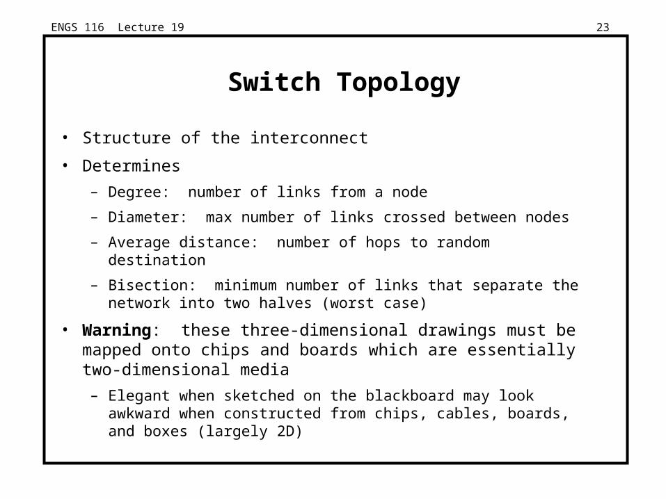
Switch Topology
• Structure of the interconnect
• Determines
– Degree: number of links from a node
– Diameter: max number of links crossed between nodes
– Average distance: number of hops to random destination
– Bisection: minimum number of links that separate the network into two halves (worst case)
• Warning: these three-dimensional drawings must be mapped onto chips and boards which are essentially two-dimensional media
– Elegant when sketched on the blackboard may look awkward when constructed from chips, cables, boards, and boxes (largely 2D)

ENGS 116 Lecture 19 24
Figure 8.15 A ring network topology.
A Simple Example

ENGS 116 Lecture 19 25
Examples of Static Interconnection Network Topologies
c) Star
a) Busb) Linear array
e) Tree
f) Near-neighbor mesh
d) Ring
g) Completely connected
h) 3–cube (hypercube)

ENGS 116 Lecture 19 26
Figure 8.16: Network topologies that have appeared in commercial MPPs.

ENGS 116 Lecture 19 27
Important Topologies
N = 1024 Type Degree Diameter Avg Dist Bisection Diam Avg D
1D mesh ≤ 2 N-1 N/3 1
2D mesh ≤ 4 2(N1/2 - 1) 2N1/2 / 3 N1/2 63 21
3D mesh ≤ 6 3(N1/3 - 1) 3N1/3 / 3 N2/3 ~ 30 ~ 10
Ring 2 N / 2 N/4 2
2D torus 4 N1/2 N1/2 / 2 2N1/2 32 16
Hypercube n n = LogN n/2 N/2 10 5

ENGS 116 Lecture 19 28
Figure 8.14 A fat-tree topology for 16 nodes.
01
23
00 0 1
45
67
01 1 1
89
1011
02 2 1
1213
1415
03 3 1
0
0
0 10 2
0 3
0

ENGS 116 Lecture 19 29
Figure 8.13 Popular switch topologies for eight nodes.

ENGS 116 Lecture 19 30
Examples of dynamic interconnection network topologies
= processor = switch
a) Crossbar switch b) 8 8 Baseline

ENGS 116 Lecture 20 31
Connection-Based vs. Connectionless
• Telephone: operator sets up connection between the caller and the receiver
– Once the connection is established, conversation can continue for hours
• Share transmission lines over long distances by using switches to multiplex several conversations on the same lines
– “Time division multiplexing” divide B/W transmission line into a fixed number of slots, with each slot assigned to a conversation
• Problem: lines busy based on number of conversations, not amount of information sent
• Advantage: reserved bandwidth

ENGS 116 Lecture 20 32
Connection-Based vs. Connectionless
• Connectionless: every package of information must have an address => packets
– Each package is routed to its destination by looking at its address
– Analogy, the postal system (sending a letter)
– Also called “Statistical multiplexing”
• Each packet requires a new/separate routing decision
• Depending on implementation the switching stations may also be called routers.
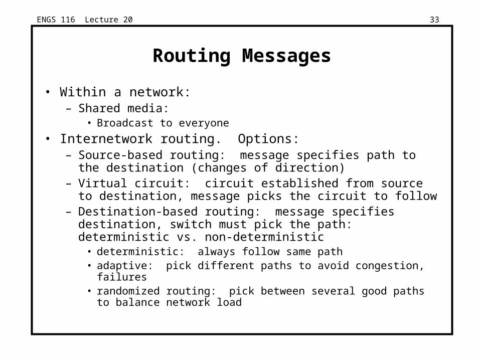
ENGS 116 Lecture 20 33
Routing Messages
• Within a network:– Shared media:
• Broadcast to everyone
• Internetwork routing. Options:– Source-based routing: message specifies path to the destination
(changes of direction)– Virtual circuit: circuit established from source to destination,
message picks the circuit to follow– Destination-based routing: message specifies destination, switch
must pick the path: deterministic vs. non-deterministic• deterministic: always follow same path• adaptive: pick different paths to avoid congestion, failures• randomized routing: pick between several good paths to balance
network load

ENGS 116 Lecture 20 34
• mesh: dimension-order routing
– (x1, y1) (x2, y2)
– first x = x2 – x1,
– then y = y2 – y1,
• hypercube: edge-cube routing
– X = xox1x2 . . .xn Y = yoy1y2 . . .yn
– R = X xor Y
– Traverse dimensions of differing address in order
• tree: common ancestor
• Deadlock free?
Deterministic Routing Examples
001
000
101
100
010 110
111011

ENGS 116 Lecture 20 35
Store and Forward vs. Cut-Through
• Store-and-forward policy: each switch waits for the full packet to arrive in switch before sending to the next switch (good for WAN)
• Cut-through routing or wormhole routing: switch examines the header, decides where to send the message, and then starts forwarding it immediately
– In wormhole routing, when head of message is blocked, message stays strung out over the network, potentially blocking other messages (needs only buffer the piece of the packet that is sent between switches). CM-5 uses it, with each switch buffer being 4 bits per port.
– Cut-through routing lets the tail continue when head is blocked, “accordioning” the whole message into a single switch. (Requires a buffer large enough to hold the largest packet).

ENGS 116 Lecture 20 36
Congestion Control
• Packet switched networks do not reserve bandwidth; this leads to contention (connection-based limits input)
• Solution: prevent packets from entering until contention is reduced (e.g., freeway on-ramp metering lights)
• Options:– Packet discarding: If packet arrives at switch and no room in buffer,
packet is discarded (e.g., UDP)– Flow control: between pairs of receivers and senders;
use feedback to tell sender when allowed to send next packet• Back-pressure: separate wires to tell to stop• Window: give original sender right to send N packets before getting
permission to send more; overlaps latency of interconnection with overhead to send & receive packet (e.g., TCP), adjustable window
– Choke packets: aka “rate-based”; each packet received by busy switch in warning state sent back to the source via choke packet. Source reduces traffic to that destination by a fixed % (e.g., ATM, ICMP source quench)

ENGS 116 Lecture 20 37
Practical Issues for Interconnection Networks
• Standardization advantages:– low cost (components used repeatedly)– stability (many suppliers to chose from)
• Standardization disadvantages:– Time for committees to agree– When to standardize?
• Before anything built? => Committee does design?• Too early suppresses innovation
• Perfect interconnect vs. Fault Tolerant?– Will SW crash on single node prevent communication?
(MPP typically assumes perfect)• Reliability (vs. availability) of interconnect• Most successful system is not always the best design.

ENGS 116 Lecture 20 38
Practical Issues
Interconnection MPP LAN WAN
Example CM-5 Ethernet ATM
Standard No Yes Yes
Fault Tolerance? No Yes Yes
Hot Insert? No Yes Yes
• Standards: required for WAN, LAN!
• Fault Tolerance: Can nodes fail and still deliver messages to other nodes? Required for WAN, LAN!
• Hot Insert: If the interconnection can survive a failure, can it also continue operation while a new node is added to the interconnection? Required for WAN, LAN!

ENGS 116 Lecture 20 39
Inter-Network-Routing
• Connecting >2 networks together.
• Requires:– Addressing Hierarchy
– Common Protocols
– Courtesy and Security
• Each step in a route (hop) decides:– What first?
– Where next?
• Transparent or explicit
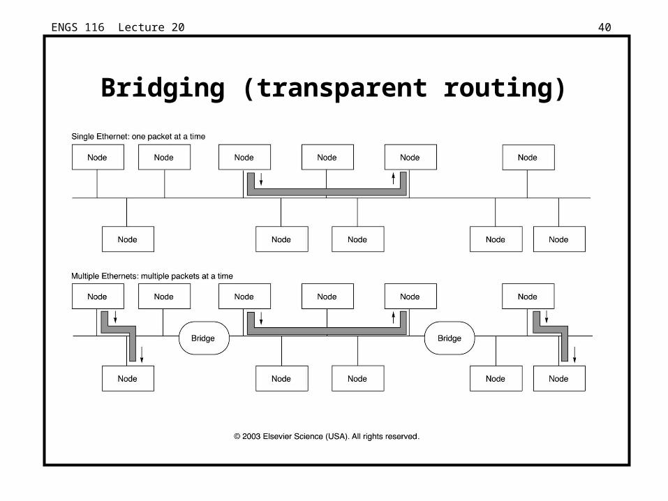
ENGS 116 Lecture 20 40
Bridging (transparent routing)

ENGS 116 Lecture 20 41
OSI model
• This one has to be in every network presentation
Electrical signals
Ethernet Frame
Packet
IP
TCP
Network library interface
Web browser
1. Physical
2. Data Link
3. Network
4. Transport
5. Session
6. Presentation
7. Application

ENGS 116 Lecture 20 42
Networking Protocols: HW/SW Interface
• Internetworking: allows computers on independent and incompatible networks to communicate reliably and efficiently;
– Enabling technologies: SW standards that allow reliable communications without reliable networks
– Hierarchy of SW layers, giving each layer responsibility for portion of overall communications task, called protocol families or protocol suites
• Transmission Control Protocol/Internet Protocol (TCP/IP)
– This protocol family is the basis of the Internet
– IP makes best effort to deliver; TCP “guarantees” delivery
– TCP/IP used even when communicating locally: NFS uses IP even though communicating across homogeneous LAN

ENGS 116 Lecture 20 43
Protocol
• Key to protocol families is that communication occurs logically at the same level of the protocol, called peer-to-peer, but is implemented via services at the lower level
• Danger is each level increases latency if implemented as hierarchy (e.g., multiple check sums)
Logical
Logical
TH TH TH TH TH TH
Actual
Actual
Actual
Actual
Actual
TH TH TH TH TH TH TH THTT TTHH
Message Message

ENGS 116 Lecture 20 44
IP, TCP, and UDP
• IP = internet protocol, used at network layer
– IP routes datagrams to destination machine, makes best effort to deliver packets but does not guarantee delivery or order of datagrams
– For IP, every host and router must have unique IP address
• IPv4 uses 32-bit addresses
• IPv6 uses 16-byte addresses (not that straight forward, though!!!)
• TCP = transmission control protocol, used at transport layer
– TCP is connection-oriented, makes guarantee of reliable, in-order delivery
– Up to 4 retries on failure to deliver (or acknowledge!)
• UDP = user data protocol, used at transport layer
– Connectionless protocol, makes no guarantees of delivery

ENGS 116 Lecture 20 45
Packet Formats
• Fields: Destination, Checksum (C), Length (L), Type (T)• Data/Header Sizes in bytes: (4 to 20)/4, (0 to 1500)/26, 48/5
LT Route
Data (4 - 20)
C
32 bits
CM-5 ATM
Destination
32 bits
C
Data (48)
T
32 bits
Preamble
Preamble
Source
Destination
Data (0 - 1500)
Pad (0 -46)Checksum
LengthLength
Destination Source
Ethernet

ENGS 116 Lecture 20 46
Networking Summary
• Protocols allow heterogeneous networking
• Protocols allow operation in the presence of failures
• Routing issues: store and forward vs. cut-through, congestion, ...
• Standardization key for LAN, WAN
• Internetworking protocols used as LAN protocols large overhead for LAN
• Integrated circuit revolutionizing networks as well as processors
• Switch is a specialized computer

ENGS 116 Lecture 20 47
Cluster (Multicomputer)
• A collection of low-cost nodes connected by a fast network.• Applications:
– Less synchronization required than for MP applications– Less need for communication– No need for one large homogeneous memory– Many copies of one application run in parallel
• Each node:– cheap– redundant
• Easily expandable– Scales if the software application scales

ENGS 116 Lecture 20 48
Applications
• Distributed Database– Each node works as the query engine for data on local disk(s)
– All nodes together implement redundancy:• Failure of 1 or more nodes doesn’t damage the database
• Scientific applications:– Nuclear or Oceanographic simulations
– Diskless nodes. Each node uses NFS (of similar SAN-based system) to access central data repository.
– Applications are started over the network.
– Think SETI@home (BOINC)