ENGLISH2 Stair Rail Care & Maintenance, Finishing Rampe … · – Power screwdriver/drill ... (#10...
32
1 ENGLISH...........................................................................2 INSTALLATION INSTRUCTIONS Stair Rail Care & Maintenance, Finishing FRANÇAIS........................................................................ 12 CONSIGNES D’INSTALLATION Rampe d’escalier Soin et entretien, apprêt ESPAÑOL........................................................................22 INSTRUCCIONES DE INSTALACIÓN Barandal de escaleras Cuidado y mantenimiento del acabado ®
-
Upload
hoangkhanh -
Category
Documents
-
view
217 -
download
4
Transcript of ENGLISH2 Stair Rail Care & Maintenance, Finishing Rampe … · – Power screwdriver/drill ... (#10...

1
ENGLISH...........................................................................2INSTALLATION INSTRUCTIONSStair Rail
Care & Maintenance, Finishing
FRANÇAIS........................................................................12CONSIGNES D’INSTALLATIONRampe d’escalier
Soin et entretien, apprêt
ESPAÑOL........................................................................22INSTRUCCIONES DE INSTALACIÓN
Barandal de escaleras
Cuidado y mantenimiento del acabado
®
EN
GLI
SH
2
AB
CDF
H
J K L M
N
O
GE
I
STAIR RAIL
Warning: Always wear safety goggles.
Need a little help installing your railing?www.rdirail.com/support/installation-videos.html
Transform is designed to exceed the most stringent building codes. For most situations everything you need is in the box. When installing spans that are greater than 91" under certain International Building Code conditions, an additional stiffener may be necessary, please check Transform’s CCR report for the most up to date technical information and install accordingly.
An evaluation report is available through your Transform Dealer RDI Customer Service or online at http://www.rdirail.com/support/code-testing-reports.html.
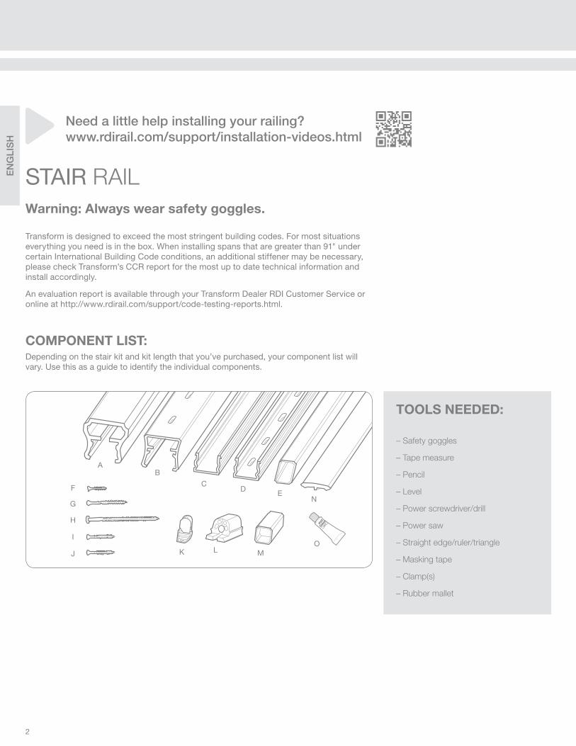
COMPONENT LIST:Depending on the stair kit and kit length that you’ve purchased, your component list will vary. Use this as a guide to identify the individual components.
– Safety goggles
– Tape measure
– Pencil
– Level
– Power screwdriver/drill
– Power saw
– Straight edge/ruler/triangle
– Masking tape
– Clamp(s)
– Rubber mallet
TOOLS NEEDED:
EN
GLI
SH
3
NEEDED FOR INSTALLATION 6' STAIR RAIL KIT 8' RAIL SECTION
A.) Top Rail 1 1
B.) Bottom Rail 1 1
C.) Bottom Beam 1 1
D.) Top Beam 1 1
E.) Balusters needed - quantities are for both square & round* balusters 15 20
F.) Set Screw (#6 x ¾") 4 4
G.) Screw (#10 x 2.5") 12 12
H.) Screw (#12 x 5") 1 2
I.) Screw (#10 x 2" - not painted - for stair/level angle application) 6 6
J.) Screw (#10 x 2" - painted to match rail color) 4 4
K.) Baluster Plug - varies by baluster type; comes pre-inserted into baluster 30 40
L.) Mounting Bracket 4 4
M.) Bottom Rail Support 1 2
N.) Resalite® Stiffener (shape varies by top rail profi le)
O.) PVC Glue (included with 6' stair kits and stair baluster boxes) 1 -
*If using round aluminum balusters, ensure that there are enough baluster shoes (sold separately) for the top and bottom of each baluster.
(Fig. 2) (Fig. 3)(Fig. 1)
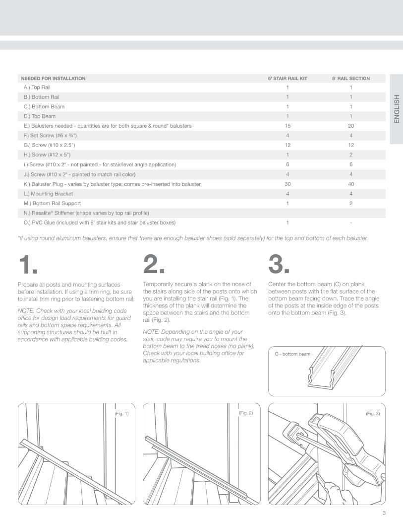
1.Prepare all posts and mounting surfaces
before installation. If using a trim ring, be sure
to install trim ring prior to fastening bottom rail.
NOTE: Check with your local building code
offi ce for design load requirements for guard
rails and bottom space requirements. All
supporting structures should be built in
accordance with applicable building codes.
2.Temporarily secure a plank on the nose of
the stairs along side of the posts onto which
you are installing the stair rail (Fig. 1). The
thickness of the plank will determine the
space between the stairs and the bottom
rail (Fig. 2).
NOTE: Depending on the angle of your
stair, code may require you to mount the
bottom beam to the tread noses (no plank).
Check with your local building offi ce for
applicable regulations.
3.Center the bottom beam (C) on plank
between posts with the fl at surface of the
bottom beam facing down. Trace the angle
of the posts at the inside edge of the posts
onto the bottom beam (Fig. 3).
C - bottom beam

EN
GLI
SH
4
6.Install a set screw on inside of rail, ensuring
set screws connect the beam with the
bracket, in the location shown in Figure 10.
This should be as close as possible to the
inside face of the bracket so that the screw
still embeds.
5.Place the bottom rail (B) with routed slots
facing up, on the plank. Slide the bottom
rail on the plank between the posts until the
distance from the edge of the post to the
baluster rout is the same at both ends (Fig. 7).
Trace the angle of the post onto the bottom
rail at both ends (Fig. 8), and cut the rail at
these marks (Fig. 9).
Tip: Use a miter saw with a carbide tip blade
of at least 60 teeth.
(Fig. 8)
(Fig. 9)
4.Wrap enough masking tape around the
bracket (Fig. 4) to make it slide snugly into
the end of the beam. Slide the bracket into
the end of the bottom beam. Align brackets
with angle marked on beam (Fig. 5) so that
when the cut is made, the entire face of the
bracket is cut but as little material is removed
as possible. With brackets secured into
bottom beam, cut through the beam and
bracket together on the marked line (Fig. 6)
to establish your installation angle.
(Fig. 5)
(Fig. 7)(Fig. 4)
(Fig. 6)
STAIR RAIL CONTINUED
(Fig. 10)
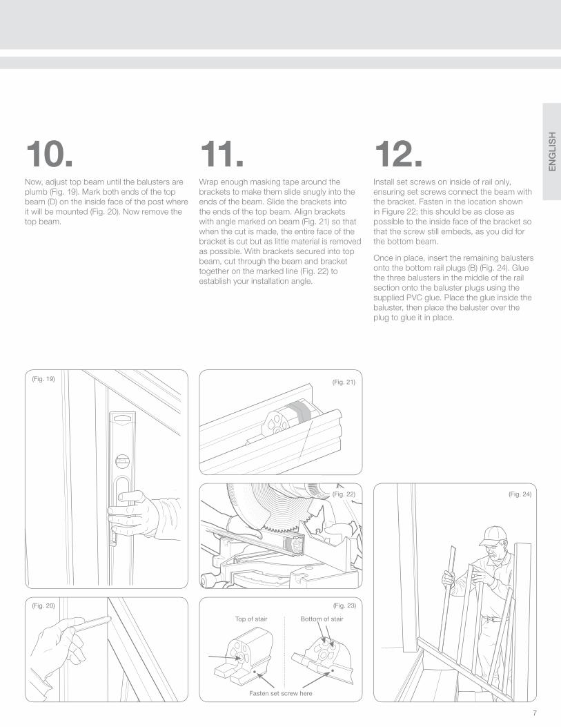
Fasten set screw here
Top of stair Bottom of stair
EN
GLI
SH
5
(Fig. 12)
(Fig. 11)
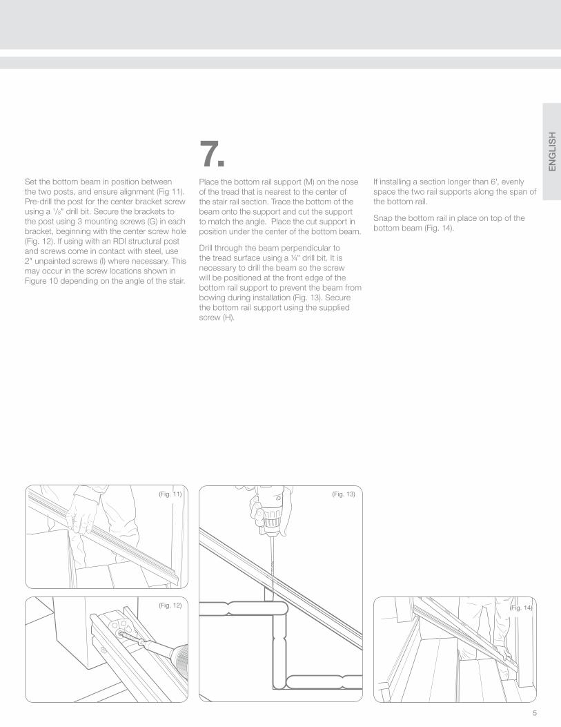
Set the bottom beam in position between
the two posts, and ensure alignment (Fig 11).
Pre-drill the post for the center bracket screw
using a 1/8" drill bit. Secure the brackets to
the post using 3 mounting screws (G) in each
bracket, beginning with the center screw hole
(Fig. 12). If using with an RDI structural post
and screws come in contact with steel, use
2" unpainted screws (I) where necessary. This
may occur in the screw locations shown in
Figure 10 depending on the angle of the stair.
7.Place the bottom rail support (M) on the nose
of the tread that is nearest to the center of
the stair rail section. Trace the bottom of the
beam onto the support and cut the support
to match the angle. Place the cut support in
position under the center of the bottom beam.
Drill through the beam perpendicular to
the tread surface using a ¼" drill bit. It is
necessary to drill the beam so the screw
will be positioned at the front edge of the
bottom rail support to prevent the beam from
bowing during installation (Fig. 13). Secure
the bottom rail support using the supplied
screw (H).
(Fig. 14)
(Fig. 13)
If installing a section longer than 6', evenly
space the two rail supports along the span of
the bottom rail.
Snap the bottom rail in place on top of the
bottom beam (Fig. 14).

EN
GLI
SH
6
(Fig. 18)
(Fig. 17)
(Fig. 16)
9.Insert a baluster onto the fi rst and last
baluster plug of the bottom rail (B) (Fig. 17).
Set the top beam (D) onto the two balusters
you installed (Fig. 18), allowing the top beam
to extend past the top and bottom post for
aligning your installation angle.
Bottom rail
Top beam
Rounded side
Rounded side
(Fig. 15)
B
A
8.NOTE: In 6' stair kits and stair baluster packs,
balusters come pre-cut at an angle of 32°. If
stairs are at a different angle, cut balusters at
required angle.
Insert baluster plugs into the bottom rail with
the rounded side of the baluster plug facing
the bottom of the stairs (Fig. 15).
Insert baluster plugs into the top beam with
the rounded side of the baluster plug facing
the top of the stairs (Fig. 15).
STAIR RAIL CONTINUED
Insert the plugs all the way into the slots so
they seat completely (Fig. 16, A), then push
the plugs to the angle required (Fig. 16, B).
Tip: You can use a rubber mallet to help tap
the baluster plugs into the bottom rail.
EN
GLI
SH
7
(Fig. 22) (Fig. 24)
11.Wrap enough masking tape around the
brackets to make them slide snugly into the
ends of the beam. Slide the brackets into
the ends of the top beam. Align brackets
with angle marked on beam (Fig. 21) so that
when the cut is made, the entire face of the
bracket is cut but as little material is removed
as possible. With brackets secured into top
beam, cut through the beam and bracket
together on the marked line (Fig. 22) to
establish your installation angle.
12.Install set screws on inside of rail only,
ensuring set screws connect the beam with
the bracket. Fasten in the location shown
in Figure 22; this should be as close as
possible to the inside face of the bracket so
that the screw still embeds, as you did for
the bottom beam.
Once in place, insert the remaining balusters
onto the bottom rail plugs (B) (Fig. 24). Glue
the three balusters in the middle of the rail
section onto the baluster plugs using the
supplied PVC glue. Place the glue inside the
baluster, then place the baluster over the
plug to glue it in place.
(Fig. 21)
(Fig. 23)
Fasten set screw here
(Fig. 19)
(Fig. 20)
10.Now, adjust top beam until the balusters are
plumb (Fig. 19). Mark both ends of the top
beam (D) on the inside face of the post where
it will be mounted (Fig. 20). Now remove the
top beam.
Top of stair Bottom of stair
EN
GLI
SH
8
(Fig. 28)
(Fig. 30)
(Fig. 29)
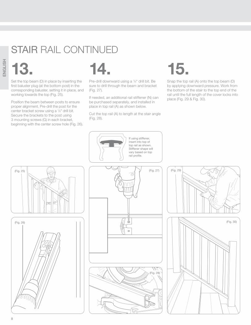
14.Pre-drill downward using a 1/8" drill bit. Be
sure to drill through the beam and bracket
(Fig. 27).
If needed, an additional rail stiffener (N) can
be purchased separately, and installed in
place in top rail (A) as shown below.
Cut the top rail (A) to length at the stair angle
(Fig. 28).
15.Snap the top rail (A) onto the top beam (D)
by applying downward pressure. Work from
the bottom of the stair to the top end of the
rail until the full length of the cover locks into
place (Fig. 29 & Fig. 30).
(Fig. 25)
(Fig. 26)
13.Set the top beam (D) in place by inserting the
fi rst baluster plug (at the bottom post) in the
corresponding baluster, setting it in place, and
working towards the top (Fig. 25).
Position the beam between posts to ensure
proper alignment. Pre-drill the post for the
center bracket screw using a 1/8" drill bit.
Secure the brackets to the post using
3 mounting screws (G) in each bracket,
beginning with the center screw hole (Fig. 26).
(Fig. 27)
STAIR RAIL CONTINUED
If using stiffener, insert into top of top rail as shown. Stiffener shape will vary based on top rail profi le.
EN
GLI
SH
9
Formula 409® is a registered trademark of The Clorox Company
Glass Plus® is a registered trademark used under authority of Reckitt Benckiser, LLC.
Comet®, Mr. Clean®, and Spic and Span® are registered trademarks of the Procter and
Gamble Company
Soft Scrub® is a registered trademark of Henkel Consumer Goods, Inc.
In general, the following chemicals may be safely used with Transform acrylic capped railing system at ambient temperature conditions:
• Formula 409® Cleaner
• Glass Plus® Cleaner
• Liquid Comet® Cleaner
• Mineral Oil
• Mr. Clean® Cleaner
• Soap and water
• Soft Scrub® Cleaner
• Spic and Span® Cleaner
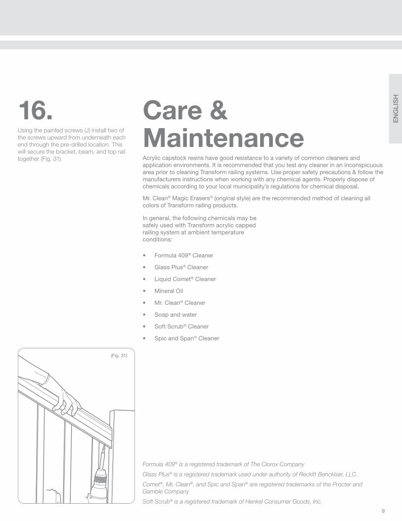
16.Using the painted screws (J) install two of
the screws upward from underneath each
end through the pre-drilled location. This
will secure the bracket, beam, and top rail
together (Fig. 31).
(Fig. 31)
Acrylic capstock resins have good resistance to a variety of common cleaners and application environments. It is recommended that you test any cleaner in an inconspicuous area prior to cleaning Transform railing systems. Use proper safety precautions & follow the manufacturers instructions when working with any chemical agents. Properly dispose of chemicals according to your local municipality’s regulations for chemical disposal.
Mr. Clean® Magic Erasers® (original style) are the recommended method of cleaning all colors of Transform railing products.
Care & Maintenance
EN
GLI
SH
10
Railing Dynamics, Inc. (“RDI”) warrants to the original consumer/purchaser (the “Purchaser”) of RDI’s rigid vinyl and Resalite™ railing and accessory
products (the “Product”) that they will remain free from material defects in workmanship and materials and will not peel, rot, rust or suffer structural
damage from weather infl uences, fungal decay or wood-boring insects, subject to the following limitations, exclusions and conditions for the time periods
defi ned below:
1. Warranty periods below are from the date of the original purchase of the Product:
a. Lifetime for individual homeowners for their residence (where product was originally installed)
b. 20 years – for commercial or governmental use
c. All colors other than white – 20 years for individual home owners for their residences and commercial and governmental use
2. This Warranty covers the Product only if it is purchased and used exclusively in North America.
3. This Warranty may be transferred one time, within fi ve years from the date of original purchase of the Product, to a subsequent buyer of the property
upon which the Product was originally installed. As a condition to the effectiveness of any such transfer, the transferee must send written notice to RDI (at
the address above) of the transfer, together with suffi cient information for RDI to determine that the transfer is valid in accordance with the terms of this
Warranty, within 30 days of the purported transfer. No other transfer or assignment of this Warranty will be valid, and any purported transfer or assignment
of rights under this Warranty will void this Warranty.
4. To make a claim under this Warranty, the Purchaser must send to RDI, at its address provided, written during the warranty period, a reasonably
detailed written notice of any defect, damage or other failure of the Product within a reasonable time after discovery of the basis for the claim. RDI may
require proof of purchase, the product serial number, a clear photograph of the defective part(s) and actual part(s) themselves. If RDI determines that
the Purchaser has a valid claim under this Warranty, RDI, at its option, will either: (i) ship to the Purchaser (at his/her address stated in the Warranty
Registration Form) a replacement for the part(s) subject to the warranty claim, free of charge to the Purchaser (but the replacement part may vary in color
or fi nish as a result of weathering or normal discoloration of the original Product or changes in RDI’s offerings of colors/fi nishes); (ii) will repair or restore the
part(s) subject to the warranty claim, free of charge to the Purchaser, provided the Purchaser provides all reasonable cooperation; or (iii) send payment to
the Purchaser of the portion of the purchase price paid by the Purchaser to RDI for the part(s) subject to the warranty claim. This paragraph provides the
Purchaser’s exclusive remedy under this Warranty. Under no circumstances will RDI be liable for any installation, removal or reinstallation of the Product
or any part, or for any labor, loss of time, maintenance or inconvenience.
5. This Warranty does not cover normal weathering effects or normal discoloration of surfaces due to exposure to ultraviolet light (e.g., sunlight) or
extremes of temperature or pressure. This Warranty does not cover defects, damage or other failure resulting from or relating to the impact of any foreign
object, hail, high winds, fl ood, earthquake, lightning or other weather disturbance, fi re, act of God, pollutant, chemical, waste, hazardous material or
other cause beyond RDI’s control.
6. THIS WARRANTY DOES NOT APPLY TO, AND UNDER NO CIRCUMSTANCES WILL RDI BE LIABLE FOR, ANY DEFECT, DAMAGE OR FAILURE
RESULTING FROM OR RELATING TO ANY MISUSE, ABUSE, NEGLECT, FAULTY OR IMPROPER INSTALLATION OR FAILURE TO ADHERE TO
ANY INSTRUCTION OR RECOMMENDATION IN RDI’S INSTALLATION INSTRUCTIONS INCLUDED WITH THE PRODUCT (THE “INSTALLATION
INSTRUCTIONS”). THIS WARRANTY WILL BE VOID AS TO ANY SURFACE OF THE PRODUCT COVERED WITH GREASE, OIL, ACID OR ANY
OTHER FOREIGN MATTER, EXCEPT AS RECOMMENDED IN THE INSTALLATION INSTRUCTIONS. THIS WARRANTY WILL BE VOID IF ANY PART
OF THE PRODUCT IS ALTERED OR IF ANY STRUCTURAL PART OR COMPONENT NOT SUPPLIED BY RDI IS USED IN CONJUNCTION WITH THE
PRODUCT, OTHER THAN APPROPRIATE USE OF DECK JOISTS OR OTHER SUPPORT STRUCTURES IN ACCORDANCE WITH THE INSTALLATION
INSTRUCTIONS. THIS WARRANTY WILL NOT COVER ANY CONSEQUENCE OF ANY DEFECT IN, DAMAGE TO OR OTHER FAILURE OF ANY DECK
JOISTS OR OTHER SUPPORT STRUCTURES (OR ANY COMPONENT THEREOF). THIS WARRANTY WILL BE VOID IF THE PRODUCT IS USED IN
VIOLATION OF ANY APPLICABLE BUILDING CODE, ZONING ORDINANCE, FIRE MARSHAL’S ORDER OR ANY OTHER LAW, REGULATION, ORDER,
STANDARD, GUIDELINE OR RECOMMENDATION OF A GOVERNMENTAL OR JUDICIAL BODY.
7. RDI DOES NOT WARRANT SLIP RESISTANCE OF THE PRODUCT. RDI WILL HAVE NO LIABILITY FOR ANY SLIP OR FALL ON OR FROM THE
PRODUCT. UNDER NO CIRCUMSTANCES WILL RDI BE LIABLE FOR ANY PROPERTY DAMAGE, BODILY INJURY OR DEATH.
8. UNDER NO CIRCUMSTANCES WILL RDI BE LIABLE FOR ANY CONSEQUENTIAL, INCIDENTAL, SPECIAL, EXEMPLARY OR PUNITIVE DAMAGES,
AND IN NO EVENT WILL RDI’S LIABILITY RELATING TO ANY PRODUCT OR PART EXCEED THE PURCHASE PRICE PAID BY THE PURCHASER TO
RDI FOR SUCH PRODUCT OR PART. Some states do not allow the exclusion or limitation of consequential or incidental damages, so the preceding
sentence may not apply to the Purchaser in such states.
9. Except as expressly set forth in this Warranty, all purchasers of the Product will be purchasing the Product “AS IS AND WITH ALL FAULTS” and
without any representation, warranty, promise, guaranty or other assurance of any kind, express, implied or statutory. Except as expressly set forth in
this Warranty, RDI HEREBY EXPRESSLY DISCLAIMS ANY REPRESENTATION, WARRANTY, PROMISE, GUARANTY OR OTHER ASSURANCE OF ANY
KIND, EXPRESS OR IMPLIED, ORAL OR WRITTEN, STATUTORY OR OTHERWISE, RELATING TO THE PRODUCT, INCLUDING BUT NOT LIMITED TO
AS TO MERCHANTABILITY, FITNESS FOR ANY PURPOSE (OTHER THAN USES EXPRESSLY DIRECTED OR RECOMMENDED IN THE INSTALLATION
INSTRUCTIONS), QUALITY, RELIABILITY, WORKMANSHIP, MATERIALS, ABSENCE OF DEFECTS (LATENT OR PATENT), ABSENCE OF DANGEROUS
CONDITIONS, CORRESPONDENCE TO ANY DESCRIPTION OR THE LIKE. NO DISTRIBUTOR, DEALER OR OTHER PERSON IS AUTHORIZED BY RDI
TO CHANGE THIS WARRANTY OR TO MAKE ANY ADDITIONAL REPRESENTATION, WARRANTY, PROMISE, GUARANTY OR OTHER ASSURANCE
ON BEHALF OF RDI RELATING TO THE PRODUCT.
To begin your warranty coverage, fi ll out the form to the right and mail to:
WARRANTY
Railing Dynamics, Inc.135 Steelmanville RoadEgg Harbor Township, NJ 08234
OR
Register online at: www.rdirail.com/warranty

EN
GLI
SH
11
FILL OUT & MAIL THIS FORM TO REGISTER PRODUCT WARRANTYComplete only one registration per installation or product. For multiple product purchases, complete one warranty card and list the serial numbers for
remaining products. PLEASE COMPLETE YOUR REGISTRATION WITHIN THIRTY (30) DAYS OF PURCHASE.
Name of Customer:
Address:
City: State: Zip:
E-mail:
Name of Supplier: City:
Date of Purchase: / / Date of Installation: / /
Customer Signature Date
HOMEOWNER’S REGISTRATIONREGISTER ONLINE AT: WWW.RDIRAIL.COM/WARRANTY OR
PL
EA
SE
PR
INT
Product Line
Titan Pro Endurance Transform RDI Metal Works Excalibur RDI Metal Works Avalon Vinyl Hand Rail Aluminum Hand Rail
Product Color
White or Satin White Earth Sahara Black or Satin Black Bronze Ironstone Wheat Caramel
Did you install this product yourself?
Yes No If no, who was your installer?________________________________________________________________________________
Where is this product installed?
Home Business Front porch Back porch/deck
What type of post was used for this installation?
Vinyl sleeve over wood Vinyl sleeve over structural post Metal post Wooden post
What kind of deck is your railing installed on?
Wood Composite Concrete If wood or composite, what color? ______________________________________________________
How did you hear about RDI?
Store Salesperson Display Trade Show Magazine Web Referral Other _______________
What sources of information did you use to choose our product?
Brochure Sales Person Web Site Display Other _______________
Please rate the quality of your experience with the:
Instructions Clear and easy to follow Understandable Difficult and Confusing
Installation Simple Somewhat easy, but glad I had instructions Felt like I was trying to build a space shuttle
Please list any other suggestions or ideas for RDI’s products and services:
_________________________________________________________________________________________________________________________
_________________________________________________________________________________________________________________________
Please list all product serial numbers:

FR
AN
ÇA
IS
12
AB
CDF
H
J K L M
N
O
GE
I
Transform est conçu pour surpasser les codes de bâtiment les plus rigoureux. Pour la plupart des cas, tout ce dont vous avez besoin se trouve dans la boîte. Quand vous installez des portées supérieures à 91" (2,31m) sous certaines conditions du code de bâtiment international, une pièce de renforcement supplémentaire pourrait s’avérer nécessaire, veuillez vérifi er le rapport CCR de Transform pour les dernières informations techniques actualisées et procéder à l’installation en conséquence.
Un rapport d’évaluation est disponible auprès du service clientèle de votre représentant RDI de Transform ou en ligne à http://www.rdirail.com/support/code-testing-reports.html.
LISTE DES ÉLÉMENTS:Dépendamment de l’ensemble de rampes d’escalier et de la longueur de l’ensemble que vous avez acheté, la liste des éléments peut varier. Utilisez ceci comme guide afi n d’identifi er les éléments individuels.
RAMPE D’ESCALIER
Avertissement: Toujours porter des lunettes de protection.
Avez-vous besoin d’un peu d’aide pour installer votre rampe? www.rdirail.com/support/installation-videos.html
– Lunettes de protection
– Ruban à mesurer
– Crayon
– Niveau
– Visseuse/Perceuse
– Scie électrique
– Règle droite/Règle /Équerre
– Ruban de masquage
– Serre-joint
– Maillet en caoutchouc
OUTILS NÉCESSAIRES:

FR
AN
ÇA
IS
13
NÉCESSAIRES À L’INSTALLATION ENSEMBLE DE
LISSES DE 6' (1,83m)
ENSEMBLE DE
LISSES DE 8' (2,44m)
A.) Main courante profi lée 1 1
B.) Longeron inférieur pré perforé 1 1
C.) Lisse basse 1 1
D.) Longeron supérieur pré perforé 1 1
E.) Balustres nécessaires - quantités pour balustres carrés et arrondis* 15 20
F.) Vis de réglage (no. 6 x ¾" / no. 6 x 1,9cm) 4 4
G.) Vis (no. 10 x 2½" / no. 10 x 6,35cm) 12 12
H.) Vis (no. 12 x 5" / no. 12 x 12,7cm) 1 2
I.) Vis (no. 10 x 2" / no. 10 x 5,08cm) - non peintes - pour application escalier/angle étage) 6 6
J.) Vis (no. 10 x 2" / no. 10 x 5,08cm) - peinte pour correspondre à la couleur de la traverse) 4 4
K.) Adaptateur de balustre - varie suivant le type de balustre; déjà inséré dans le balustre 30 40
L.) Support d’attache 4 4
M.) Cale de soutien 1 2
N.) Pièce de renforcement Resalite® (la forme varie suivant le profi lé de la main courante)
O.) Colle à PVC (incluse avec les ensembles d’escaliers de 6' (1,83m) et les boîtes de balustres d’escalier)
1 -
* Si vous utilisez des balustres ronds en aluminium, assurez-vous qu’il y a suffi samment d’adaptateurs de balustres (vendus séparément) pour le
haut et le bas de chaque balustre.
(Fig. 2) (Fig. 3)(Fig. 1)
1.Préparez tous les poteaux et les surfaces de
montage avant l’installation. Si vous utilisez une
base de poteau, assurez-vous d’installer cette
dernière avant de sécuriser la lisse basse.
REMARQUE: Vérifi ez auprès de votre code
du bâtiment local pour ce qui est exigé en
matière de charge nominale pour les rampes
et quel dégagement est exigé sous la rampe.
Toutes les structures d’appui doivent être
construites conformément aux codes du
bâtiment en vigueur.
2.Sécurisez temporairement un madrier sur
les nez des marches d’escalier, le long des
poteaux sur lesquels vous installez la lisse
basse (Figure 1). L’épaisseur du madrier
déterminera le dégagement entre les
escaliers et la lisse basse (Figure 2).
REMARQUE: Dépendamment de l’angle de
votre escalier, le code pourrait exiger que
vous montiez la lisse basse sur les nez de
marche (et non pas sur le madrier). Vérifi ez
auprès du code du bâtiment local pour
consulter les règlements en vigueur.
3.Centrez la lisse basse (C) sur le madrier entre
les poteaux, la surface plate de la lisse basse
face au sol. Tracez l’angle des poteaux sur le
bord interne des poteaux sur la lisse basse
(Figure 3).
C - Lisse basse
FR
AN
ÇA
IS
14
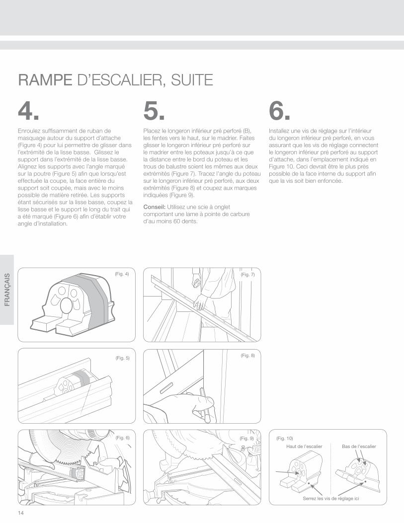
6.Installez une vis de réglage sur l’intérieur
du longeron inférieur pré perforé, en vous
assurant que les vis de réglage connectent
le longeron inférieur pré perforé au support
d’attache, dans l’emplacement indiqué en
Figure 10. Ceci devrait être le plus près
possible de la face interne du support afi n
que la vis soit bien enfoncée.
5.Placez le longeron inférieur pré perforé (B),
les fentes vers le haut, sur le madrier. Faites
glisser le longeron inférieur pré perforé sur
le madrier entre les poteaux jusqu’à ce que
la distance entre le bord du poteau et les
trous de balustre soient les mêmes aux deux
extrémités (Figure 7). Tracez l’angle du poteau
sur le longeron inférieur pré perforé, aux deux
extrémités (Figure 8) et coupez aux marques
indiquées (Figure 9).
Conseil: Utilisez une scie à onglet
comportant une lame à pointe de carbure
d’au moins 60 dents.
(Fig. 8)
(Fig. 9)
4.Enroulez suffi samment de ruban de
masquage autour du support d’attache
(Figure 4) pour lui permettre de glisser dans
l’extrémité de la lisse basse. Glissez le
support dans l’extrémité de la lisse basse.
Alignez les supports avec l’angle marqué
sur la poutre (Figure 5) afi n que lorsqu’est
effectuée la coupe, la face entière du
support soit coupée, mais avec le moins
possible de matière retirée. Les supports
étant sécurisés sur la lisse basse, coupez la
lisse basse et le support le long du trait qui
a été marqué (Figure 6) afi n d’établir votre
angle d’installation.
(Fig. 5)
(Fig. 7)(Fig. 4)
(Fig. 6)
RAMPE D’ESCALIER, SUITE
(Fig. 10)
Serrez les vis de réglage ici
Haut de l’escalier Bas de l’escalier

FR
AN
ÇA
IS
15
(Fig. 12)
(Fig. 11)
Placez la lisse basse en position entre
les deux poteaux et assurez-vous de
l’alignement (Figure 11). Pré trouez le poteau
pour la vis de support du centre en utilisant
une mèche de 1/8" (0,32cm). Sécurisez
les supports au poteau à l’aide de 3 vis
de montage (G) sur chaque support, en
débutant par le trou de la vis du centre
(Figure 12). Si en l’utilisant avec un poteau
structurel RDI et des vis, vous entrez en
contact avec de l’acier, utilisez alors les
vis non peintes de 2"/ (5,08cm) (1) lorsque
nécessaire. Ceci peut se produire aux
endroits des vis indiqués en Figure 10,
dépendamment de l’angle de l’escalier.
7.Placez la cale de soutien de la lisse basse (M)
sur le nez de marche le plus proche du centre
de la section de la rampe. Tracez le bas de la
lisse basse sur la cale de soutien et coupez la
cale afi n qu’elle corresponde à l’angle. Placez
la cale de soutien coupée en position sous le
centre de la lisse basse.
Percez la lisse perpendiculairement à la surface
de la marche en utilisant une mèche de ¼"
(0,64cm). Il convient de percer la lisse afi n que
la vis se positionne sur le bord avant de la cale
de support pour éviter que la lisse ne se courbe
durant l’installation (Figure 13). Sécurisez la cale
de soutien à l’aide de la vis fournie (H).
(Fig. 14)
(Fig. 13)
Si vous installez une section de plus de 6'
(1,83m), espacez à égale distance les deux
cales de soutien le long de la portée de la
lisse basse.
Enclenchez le longeron inférieur pré perforé
en place sur la lisse basse (Figure 14).

FR
AN
ÇA
IS
16
(Fig. 18)
(Fig. 17)
(Fig. 16)
9.Insérez un balustre sur le premier et le
dernier trou du longeron inférieur pré perforé
(B) (Figure 17).
Placez le longeron supérieur pré perforé (D)
sur les deux balustres que vous avez installés
(Figure 18), laissant le longeron supérieur
pré perforé dépasser le poteau supérieur et
inférieur pour aligner votre angle d’installation.
Bottom rail
Top beam
Rounded side
Rounded side
(Fig. 15)
B
A
8.REMARQUE: Dans les ensembles d’escaliers
de 6' (1,83m) et les ensembles de balustres
d’escaliers, les balustres sont pré coupés à un
angle de 32°. Si les escaliers sont à un angle
différent, coupez les balustres à l’angle exigé.
Insérez les adaptateurs de balustres dans le
longeron inférieur pré perforé, le côté arrondi
de l’adaptateur de balustre faisant face au bas
des escaliers (Figure 15).
Insérez les adaptateurs de balustres dans le
longeron supérieur pré perforé, le côté arrondi
de l’adaptateur de balustre faisant face au
haut de l’escalier (Figure 15).
Insérez les adaptateurs jusqu’au bout dans
les fentes afi n qu’ils se placent complètement
(Figure 16, A) puis poussez les adaptateurs à
l’angle désiré (Figure 16, B).
Conseil: Vous pouvez utiliser un maillet
en caoutchouc pour aider à introduire les
adaptateurs de balustre dans le longeron
inférieur pré perforé.
Longeron supérieur pré perforé
Longeron inférieur pré perforé
Côté arrondi
Côté arrondi
RAMPE D’ESCALIER, SUITE
FR
AN
ÇA
IS
17
(Fig. 22) (Fig. 24)
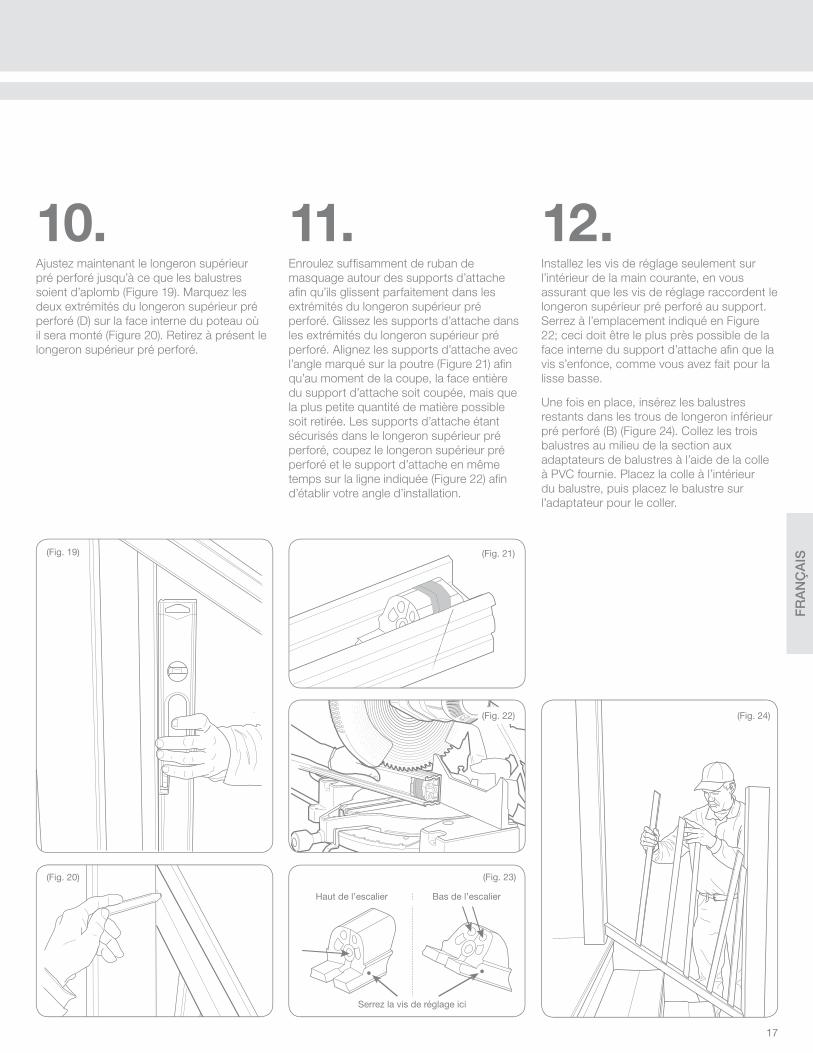
11.Enroulez suffi samment de ruban de
masquage autour des supports d’attache
afi n qu’ils glissent parfaitement dans les
extrémités du longeron supérieur pré
perforé. Glissez les supports d’attache dans
les extrémités du longeron supérieur pré
perforé. Alignez les supports d’attache avec
l’angle marqué sur la poutre (Figure 21) afi n
qu’au moment de la coupe, la face entière
du support d’attache soit coupée, mais que
la plus petite quantité de matière possible
soit retirée. Les supports d’attache étant
sécurisés dans le longeron supérieur pré
perforé, coupez le longeron supérieur pré
perforé et le support d’attache en même
temps sur la ligne indiquée (Figure 22) afi n
d’établir votre angle d’installation.
12.Installez les vis de réglage seulement sur
l’intérieur de la main courante, en vous
assurant que les vis de réglage raccordent le
longeron supérieur pré perforé au support.
Serrez à l’emplacement indiqué en Figure
22; ceci doit être le plus près possible de la
face interne du support d’attache afi n que la
vis s’enfonce, comme vous avez fait pour la
lisse basse.
Une fois en place, insérez les balustres
restants dans les trous de longeron inférieur
pré perforé (B) (Figure 24). Collez les trois
balustres au milieu de la section aux
adaptateurs de balustres à l’aide de la colle
à PVC fournie. Placez la colle à l’intérieur
du balustre, puis placez le balustre sur
l’adaptateur pour le coller.
(Fig. 21)
(Fig. 23)
Serrez la vis de réglage ici
(Fig. 19)
(Fig. 20)
10.Ajustez maintenant le longeron supérieur
pré perforé jusqu’à ce que les balustres
soient d’aplomb (Figure 19). Marquez les
deux extrémités du longeron supérieur pré
perforé (D) sur la face interne du poteau où
il sera monté (Figure 20). Retirez à présent le
longeron supérieur pré perforé.
Haut de l’escalier Bas de l’escalier
FR
AN
ÇA
IS
18
(Fig. 28)
(Fig. 30)
(Fig. 29)
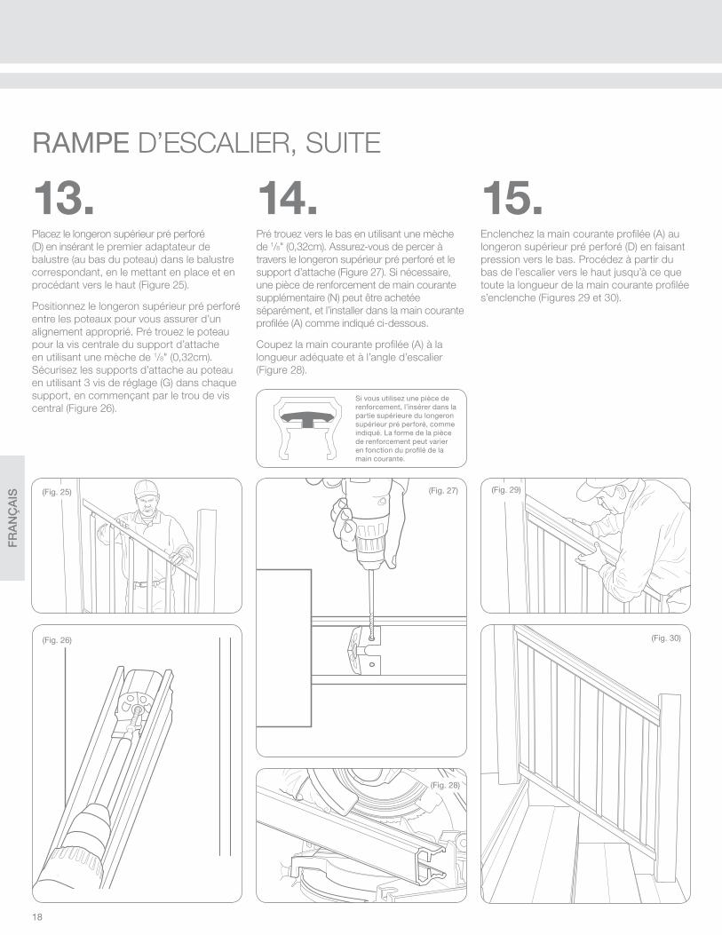
14.Pré trouez vers le bas en utilisant une mèche
de 1/8" (0,32cm). Assurez-vous de percer à
travers le longeron supérieur pré perforé et le
support d’attache (Figure 27). Si nécessaire,
une pièce de renforcement de main courante
supplémentaire (N) peut être achetée
séparément, et l’installer dans la main courante
profi lée (A) comme indiqué ci-dessous.
Coupez la main courante profi lée (A) à la
longueur adéquate et à l’angle d’escalier
(Figure 28).
15.Enclenchez la main courante profi lée (A) au
longeron supérieur pré perforé (D) en faisant
pression vers le bas. Procédez à partir du
bas de l’escalier vers le haut jusqu’à ce que
toute la longueur de la main courante profi lée
s’enclenche (Figures 29 et 30).
(Fig. 25)
(Fig. 26)
13.Placez le longeron supérieur pré perforé
(D) en insérant le premier adaptateur de
balustre (au bas du poteau) dans le balustre
correspondant, en le mettant en place et en
procédant vers le haut (Figure 25).
Positionnez le longeron supérieur pré perforé
entre les poteaux pour vous assurer d’un
alignement approprié. Pré trouez le poteau
pour la vis centrale du support d’attache
en utilisant une mèche de 1/8" (0,32cm).
Sécurisez les supports d’attache au poteau
en utilisant 3 vis de réglage (G) dans chaque
support, en commençant par le trou de vis
central (Figure 26).
(Fig. 27)
Si vous utilisez une pièce de renforcement, l’insérer dans la partie supérieure du longeron supérieur pré perforé, comme indiqué. La forme de la pièce de renforcement peut varier en fonction du profi lé de la main courante.
RAMPE D’ESCALIER, SUITE
FR
AN
ÇA
IS
19
Formula 409® est une marque déposée de The Clorox Company
Glass Plus® est une marque déposée utilisée sous l’autorité de Reckitt Benckiser, LLC.
Comet®, Mr. Clean®, et Spic and Span® sont des marques déposées de
Procter and Gamble Company
Soft Scrub® est une marque déposée de Henkel Consumer Goods, Inc.
En général, les produits chimiques suivants peuvent être utilisés à la température ambiante en toute sécurité sur le système de rampe Transform recouvert d’acrylique:
• Formula 409® Nettoyant
• Glass Plus® Nettoyant
• Liquid Comet® Nettoyant
• Huile minérale
• Mr. Clean® Nettoyant
• Eau et savon
• Soft Scrub® Nettoyant
• Spic and Span® Nettoyant
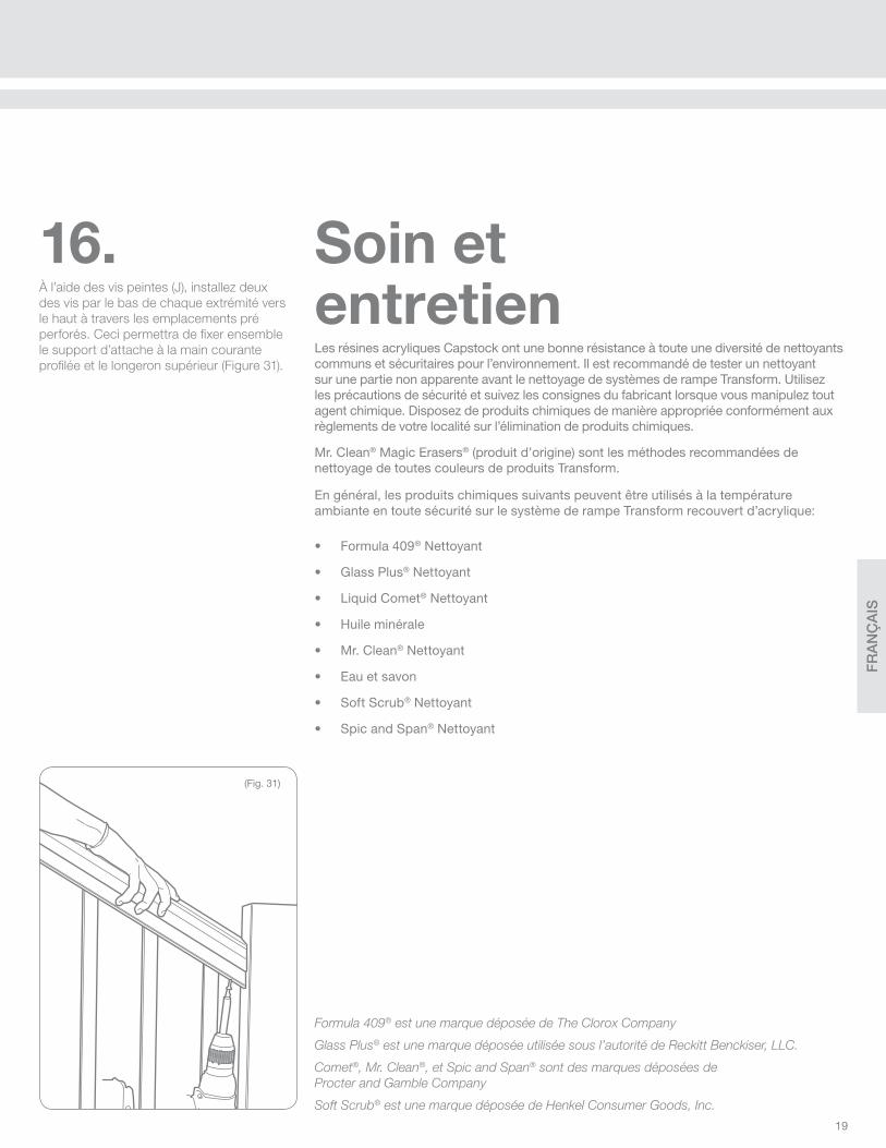
16.À l’aide des vis peintes (J), installez deux
des vis par le bas de chaque extrémité vers
le haut à travers les emplacements pré
perforés. Ceci permettra de fi xer ensemble
le support d’attache à la main courante
profi lée et le longeron supérieur (Figure 31).
(Fig. 31)
Les résines acryliques Capstock ont une bonne résistance à toute une diversité de nettoyants communs et sécuritaires pour l’environnement. Il est recommandé de tester un nettoyant sur une partie non apparente avant le nettoyage de systèmes de rampe Transform. Utilisez les précautions de sécurité et suivez les consignes du fabricant lorsque vous manipulez tout agent chimique. Disposez de produits chimiques de manière appropriée conformément aux règlements de votre localité sur l’élimination de produits chimiques.
Mr. Clean® Magic Erasers® (produit d’origine) sont les méthodes recommandées de nettoyage de toutes couleurs de produits Transform.
Soin et entretien

FR
AN
ÇA
IS
20
Railing Dynamics, Inc. (“RDI”) garantit au consommateur/acheteur d’origine (“l’Acheteur”) de balustrade et produits accessoires en vinyle rigide de
RDI et en Resalite™ (le “Produit”) qu’ils resteront sans défauts matériels de fabrication et de matériaux et qu’ils ne pèleront pas, ne pourriront pas, ne
rouilleront pas ou ne subiront pas des dommages structurels à cause des intempéries, de la carie fongique ou des insectes xylophages, sous réserve
des restrictions, exclusions et conditions suivantes pour les périodes défi nies ci-dessous:
1. Les périodes de garantie ci-dessous commencent à la date de l’achat initial du produit:
a. Durée à vie pour les propriétaires individuels pour leur résidence (où le produit a été installé à l’origine)
b. 20 ans - pour un usage commercial ou gouvernemental
c. Toutes les couleurs autres que le blanc - 20 ans pour les propriétaires individuels pour leurs résidences et pour usage commercial et gouvernemental
2. Cette garantie ne couvre le produit que si celui-ci a été acheté et utilisé exclusivement en Amérique du Nord.
3. Cette garantie ne peut être transférée qu’une seule fois, dans les cinq ans à compter de la date d’achat d’origine du produit, à un acheteur
subséquent de la propriété sur laquelle le produit a été installé à l’origine. Comme condition de la validité d’un tel transfert, le cessionnaire doit faire
parvenir un avis écrit du transfert à RDI (à l’adresse ci-dessus), ainsi que les informations suffi santes pour que RDI détermine si le transfert est valide
selon les termes de cette garantie, dans les 30 jours suivant le transfert présumé. Aucun autre transfert ou cession de cette garantie ne sera valable,
et tout prétendu transfert ou cession de droits en vertu de la présente garantie annule cette garantie.
4. Pour faire une réclamation en vertu de cette garantie, l’acheteur doit envoyer par écrit à RDI, à l’adresse fournie, un avis suffi samment détaillé, écrit
pendant la période de garantie, de tout défectuosité, dommage ou autre défaut du produit dans un délai raisonnable après la découverte que le problème
nécessite une réclamation. RDI peut exiger une preuve d’achat, le numéro de série du produit, une photographie claire de la pièce défectueuse (s) et la
ou les pièces réelle(s) elles-mêmes. Si RDI détermine que l’acheteur a un droit valable en vertu de cette garantie, RDI, à son choix : (i) enverra à l’acheteur
(à son adresse indiquée dans le formulaire d’inscription de garantie) un remplacement de la ou des pièces(s ) sous réserve de la demande de garantie,
sans frais pour l’acheteur (mais la pièce de rechange peut varier quant à la couleur ou la fi nition en raison de l’altération ou de la décoloration normale
du produit d’origine ou des changements dans l’offre de RDI en matière de couleurs ou de fi nition); (ii) s’engage à réparer ou restaurer la ou les pièces
soumise(s) à la demande de garantie, sans frais pour l’acheteur, à condition que l’acheteur fournisse toute coopération raisonnable ; ou (iii) à envoyer le
paiement, à l’acheteur, de la partie du prix d’achat payé par l’acheteur à RDI pour la ou les pièces soumise(s) à la demande de garantie. Cet alinéa prévoit
le recours exclusif de l’acheteur sous cette garantie. En aucun cas, RDI peut être tenu responsable pour toute installation, enlèvement ou réinstallation
du produit ou d’une pièce quelconque, ou pour tout travail, perte de temps, entretien ou inconvénients.
5. Cette garantie ne couvre pas les effets d’altération normale ou la décoloration normale des surfaces due à l’exposition à la lumière ultraviolette (par
exemple, la lumière du soleil) ou aux extrêmes de température ou de pression. Cette garantie ne couvre pas les défauts, dommages ou autre défaillance
résultant de, ou liés à, l’impact de tout corps étranger, de la grêle, des vents violents, des inondations, d’un tremblement de terre, de la foudre ou
d’autres perturbations de la météo, le feu, actes de la nature, polluants, produits chimiques, déchets, matières dangereuses ou toute autre cause hors
du contrôle de RDI.
6. CETTE GARANTIE NE COUVRE PAS, ET EN AUCUN CAS NE RENDRA RDI RESPONSABLE DE TOUTE DÉFECTUOSITÉ, DOMMAGES OU
DÉFAILLANCE RÉSULTANT DE, OU LIÉS À, UNE MAUVAISE UTILISATION, UN ABUS, UNE NÉGLIGENCE, UNE INSTALLATION OU LE NON-RESPECT
DE TOUTE UTILISATION OU DES RECOMMANDATIONS DÉFECTUEUSES OU INADÉQUATES DANS LES INSTRUCTIONS D’INSTALLATION QUE RDI
INCLUT AVEC LE PRODUIT (LES “INSTRUCTIONS D’INSTALLATION”). CETTE GARANTIE SERA ANNULÉE POUR TOUTE SURFACE DU PRODUIT
QUI SERAIT COUVERTE DE GRAISSE, D’HUILE, D’UN ACIDE OU DE TOUT AUTRE CORPS ÉTRANGER, SAUF SI CEUX-CI SONT RECOMMANDÉS
DANS LES INSTRUCTIONS D’INSTALLATION. CETTE GARANTIE SERA ANNULÉE SI UNE PARTIE DU PRODUIT EST MODIFIÉE OU SI UNE PARTIE
STRUCTURELLE QUELCONQUE OU UN COMPOSANT NON FOURNI PAR RDI EST UTILISÉE EN CONJONCTION AVEC LE PRODUIT, AUTRE
QUE L’USAGE APPROPRIÉ DE SOLIVES DE TERRASSE OU AUTRES STRUCTURES DE SUPPORT EN CONFORMITÉ AVEC LES INSTRUCTIONS
D’INSTALLATION. CETTE GARANTIE NE COUVRE PAS TOUT CE QUI RÉSULTE D’UNE DÉFECTUOSITÉ QUELCONQUE, DE DÉGÂTS AUX SOLIVES
OU AUTRES STRUCTURES DE SUPPORT (OU TOUT COMPOSANT). CETTE GARANTIE SERA NULLE SI LE PRODUIT EST UTILISÉ EN VIOLATION
D’UN CODE QUELCONQUE DU BÂTIMENT APPLICABLE, D’UNE ORDONNANCE DE ZONAGE, D’UN ORDRE DU COMMISSAIRE DES INCENDIES OU
TOUTE AUTRE LOI, RÉGLEMENT, DÉCRET, NORME, DIRECTIVE OU RECOMMANDATION D’ UNE INSTANCE JUDICIAIRE OU GOUVERNEMENTALE.
7. RDI NE GARANTIT PAS LA RÉSISTANCE AU GLISSEMENT DU PRODUIT. RDI N’AURA AUCUNE RESPONSABILITÉ POUR LE GLISSEMENT OU LA
CHUTE DE PERSONNES SUR LE PRODUIT OU À PARTIR DE CELUI-CI. EN AUCUN CAS RDI NE SERA RESPONSABLE POUR TOUT DÉGÂT À LA
PROPRIÉTÉ, POUR DE BLESSURES OU LA MORT.
8. EN AUCUN CAS RDI SERA RESPONSABLE DES DÉGÂTS INDIRECTS, ACCESSOIRES, SPÉCIAUX, EXEMPLAIRES OU PUNITIFS, ET EN AUCUN
CAS LA RESPONSABILITÉ DE RDI RELATIVE A TOUT PRODUIT OU PIÈCE DÉPASSERA LE PRIX D’ACHAT PAYÉ PAR L’ACHETEUR À RDI POUR CE
PRODUIT OU CETTE PIÈCE. Certains états ne permettent pas l’exclusion ou la limitation des dommages indirects ou accessoires, de sorte que la phrase
précédente peut ne pas s’appliquer à l’acheteur dans de tels états.
9. Sauf expressément énoncé dans la présente garantie, tous les acheteurs du produit achète le produit “EN L’ÉTAT ET AVEC TOUS SES DÉFAUTS” et sans
aucune représentation, garantie, promesse, autorisation ou autre assurance d’aucune sorte, expresse, implicite ou statutaire. Sauf expressément énoncé
dans la présente garantie, RDI EXCLUT TOUTE REPRÉSENTATION, GARANTIE, PROMESSE, AUTORISATION OU AUTRE ASSURANCE D’AUCUNE
SORTE, EXPLICITE OU IMPLICITE, ORALE OU ÉCRITE, LÉGALE OU AUTRE, CONCERNANT LE PRODUIT, Y COMPRIS, MAIS SANS S’Y LIMITER,
LA QUALITÉ MARCHANDE, L’ADÉQUATION À UN USAGE (AUTRES QUE LES UTILISATIONS EXPRÉSSEMENT ÉNONCÉES OU RECOMMANDÉES
DANS LES INSTRUCTIONS D’INSTALLATION), QUALITÉ, FIABILITÉ, FABRICATION DE MATÉRIAUX, ABSENCE DE DÉFAUTS (LATENTE OU
PATENTE), ABSENCE DE CONDITIONS DANGEREUSES, CORRESPONDANCE POUR TOUTE DESCRIPTION OU CHOSE SEMBLABLE. AUCUN
REVENDEUR, DISTRIBUTEUR OU AUTRE PERSONNE N’EST AUTORISÉ PAR RDI À MODIFIER CETTE GARANTIE OU À FAIRE DES DÉCLARATIONS
COMPLÉMENTAIRES, GARANTIE, PROMISE, GARANTIE OU AUTRE ASSURANCE AU NOM DE RDI CONCERNANT LE PRODUIT.
Pour commencer votre couverture de garantie, remplir le formulaire à droite et envoyer par courrier à:
GARANTIE
Railing Dynamics, Inc.135 Steelmanville RoadEgg Harbor Township, NJ 08234
OU
Inscrivez-vous en ligne à l’adresse: www.rdirail.com/warranty

FR
AN
ÇA
IS
21
Remplissez un seul enregistrement par installation ou produit. Pour les achats multiples de produits, compléter une carte de garantie et indiquer les numéros
de série des produits restants. VEUILLEZ COMPLETER VOTRE INSCRIPTION DANS LES TRENTE (30) JOURS QUI SUIVENT L’ACHAT.
Nom du client:
Adresse:
Ville: État: Code postal:
E-mail:
Nom du Fournisseur: Ville:
Date d’achat: / / Date d’installation: / /
Signature du client Date
ENREGISTREMENT DU PROPRIÉTAIRE INSCRIPTION EN LIGNE A: WWW.RDIRAIL.COM/WARRANTY OU
VE
UIL
LE
Z I
MP
RIM
ER
Gamme de produits
Titan Pro Endurance Transform RDI Metal Works Excalibur RDI Metal Works Avalon Vinyl Hand Rail Aluminum Hand Rail
Couleur du produit
Blanc ou blanc satiné Terre Sahara Noir ou satin noir Bronze Ironstone Blé Caramel
Avez-vous installé vous-même ce produit?
Oui Non Si non, qui était votre installateur?______________________________________________________________________________
Où est ce que ce produit a été installé?
Maison Entreprise Porche à l’avant de la maison Porche arrière/terrasse
Quel type de poteau a été utilisé pour cette installation?
Manchon en vinyle sur bois Manchon en vinyle sur poteau structurel Poteau en métal Poteau en bois
Sur quel type de terrasse votre balustrade est-elle installée?
Bois Composite Béton Si c’est sur du bois ou du composite, quelle en est la couleur?______________________________________
Comment avez-vous entendu parler de RDI?
Vendeur de magasin Afficher Salon Magazine Internet Référence Autre _______________
Quelles sources d’information avez-vous utilisées pour choisir notre produit?
Brochure Personnel de ventes Site Web Affichage Autre _______________
Veuillez noter la qualité de votre expérience avec:
Les instructions Claires et faciles à suivre Compréhensibles Difficiles et déroutantes
Installation Simple
Veuillez énumérer d’autres suggestions ou idées pour les produits et services de RDI:
_________________________________________________________________________________________________________________________
_________________________________________________________________________________________________________________________
Veuillez indiquer les numéros de série de tous les produits:
REMPLIR ET ENVOYER CE FORMULAIRE POUR ENREGISTRER LA GARANTIE DU PRODUIT.
Assez facile, mais content d’avoir
eu des instructions
J’ai eu l’impression que j’étais en train
de construire une navette spatiale

ES
PA
ÑO
L
22
AB
CDF
H
J K L M
N
O
GE
I
Transform está diseñado para superar los más estrictos códigos de construcción. En la mayoría de las situaciones, todo lo que necesita está en la caja. Cuando se instalan tramos de más de 91" (2,31m) bajo ciertas condiciones del código de construcción internacional, puede ser necesario utilizar un refuerzo adicional. Revise el informe CCR de Transform para obtener la información técnica más actualizada y realice la instalación en consecuencia.
Un informe de evaluación está disponible con su distribuidor de Transform, el servicio de atención al cliente de RDI o en línea en http://www.rdirail.com/support/code-testing-reports.html.
LISTA DA COMPONENTES:Según el kit para escalera y la longitud del kit que haya comprado, la lista de los componentes puede variar. Utilice esto como una guía para identifi car los componentes individuales.
BARANDAL DE ESCALERAS
Advertencia: Use siempre gafas de seguridad.
¿Necesita un poco de ayuda para instalar el barandal?www.rdirail.com/support/installation-videos.html
– Gafas de seguridad
– Cinta métrica
– Lápiz
– Nivel
– Taladro/destornillador eléctrico
– Sierra eléctrica
– Cinta de enmascarar
– Abrazaderas
– Martillo de goma
HERRAMIENTAS
NECESARIAS:
ES
PA
ÑO
L
23
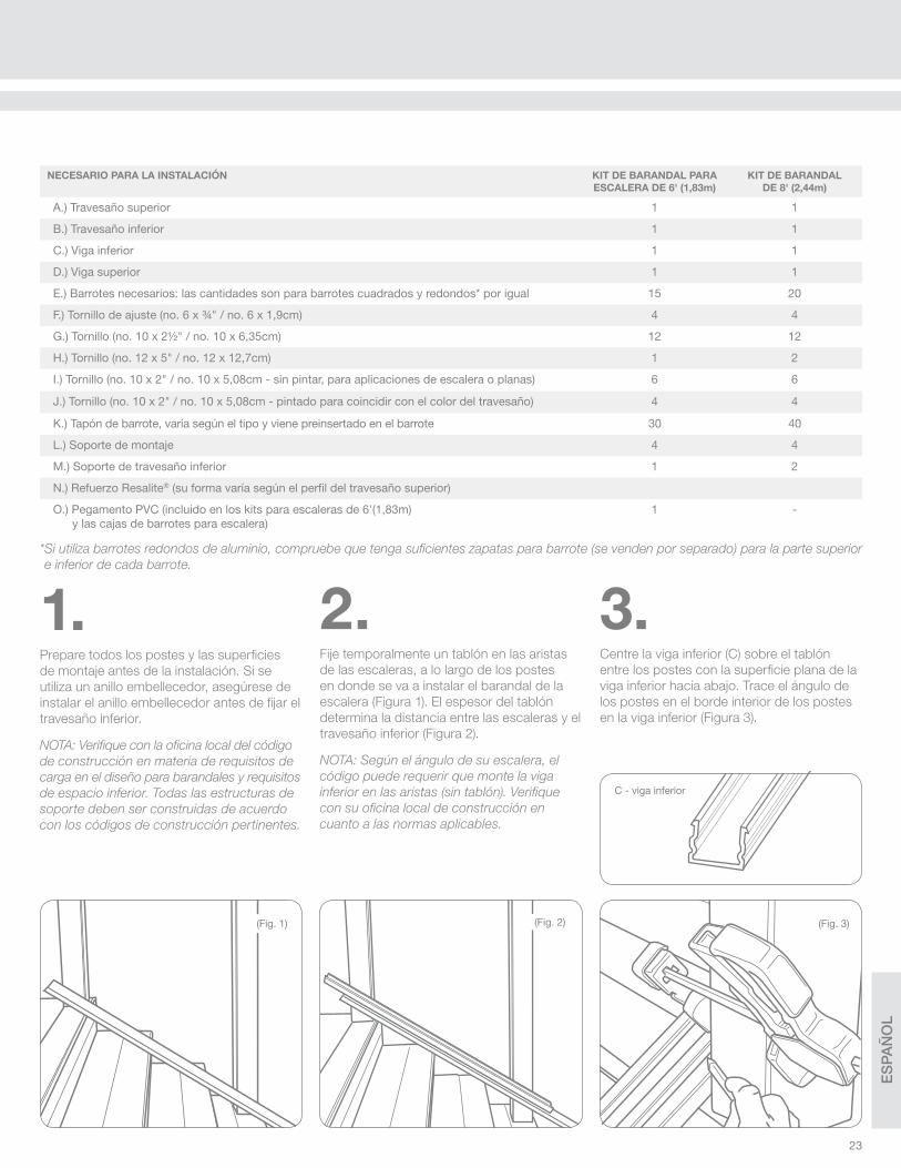
NECESARIO PARA LA INSTALACIÓN KIT DE BARANDAL PARA
ESCALERA DE 6' (1,83m)
KIT DE BARANDAL
DE 8' (2,44m)
A.) Travesaño superior 1 1
B.) Travesaño inferior 1 1
C.) Viga inferior 1 1
D.) Viga superior 1 1
E.) Barrotes necesarios: las cantidades son para barrotes cuadrados y redondos* por igual 15 20
F.) Tornillo de ajuste (no. 6 x ¾" / no. 6 x 1,9cm) 4 4
G.) Tornillo (no. 10 x 2½" / no. 10 x 6,35cm) 12 12
H.) Tornillo (no. 12 x 5" / no. 12 x 12,7cm) 1 2
I.) Tornillo (no. 10 x 2" / no. 10 x 5,08cm - sin pintar, para aplicaciones de escalera o planas) 6 6
J.) Tornillo (no. 10 x 2" / no. 10 x 5,08cm - pintado para coincidir con el color del travesaño) 4 4
K.) Tapón de barrote, varía según el tipo y viene preinsertado en el barrote 30 40
L.) Soporte de montaje 4 4
M.) Soporte de travesaño inferior 1 2
N.) Refuerzo Resalite® (su forma varía según el perfi l del travesaño superior)
O.) Pegamento PVC (incluido en los kits para escaleras de 6'(1,83m) y las cajas de barrotes para escalera)
1 -
* Si utiliza barrotes redondos de aluminio, compruebe que tenga sufi cientes zapatas para barrote (se venden por separado) para la parte superior
e inferior de cada barrote.
(Fig. 2) (Fig. 3)(Fig. 1)
1.Prepare todos los postes y las superfi cies
de montaje antes de la instalación. Si se
utiliza un anillo embellecedor, asegúrese de
instalar el anillo embellecedor antes de fi jar el
travesaño inferior.
NOTA: Verifi que con la ofi cina local del código
de construcción en materia de requisitos de
carga en el diseño para barandales y requisitos
de espacio inferior. Todas las estructuras de
soporte deben ser construidas de acuerdo
con los códigos de construcción pertinentes.
2.Fije temporalmente un tablón en las aristas
de las escaleras, a lo largo de los postes
en donde se va a instalar el barandal de la
escalera (Figura 1). El espesor del tablón
determina la distancia entre las escaleras y el
travesaño inferior (Figura 2).
NOTA: Según el ángulo de su escalera, el
código puede requerir que monte la viga
inferior en las aristas (sin tablón). Verifi que
con su ofi cina local de construcción en
cuanto a las normas aplicables.
3.Centre la viga inferior (C) sobre el tablón
entre los postes con la superfi cie plana de la
viga inferior hacia abajo. Trace el ángulo de
los postes en el borde interior de los postes
en la viga inferior (Figura 3).
C - viga inferior

ES
PA
ÑO
L
24
6.Instale un tornillo de ajuste en el interior del
travesaño, y compruebe que los tornillos de
ajuste conecten con la viga con el soporte,
en el lugar que se muestra en la Figura 10.
Esto debería de ser lo más cerca posible de
la cara interior del soporte de modo que el
tornillo todavía se incorpore.
5.Coloque el travesaño inferior (B) con las
ranuras hacia arriba, sobre el tablón. Deslice
el travesaño inferior sobre el tablón entre los
postes hasta que la distancia desde el borde
del poste hasta la ranura para el barrote sea
la misma en ambos extremos (Figura 7).
Trace el ángulo del poste en el travesaño
inferior en ambos extremos (Figura 8), y corte
el travesaño en estas marcas (Figura 9).
Sugerencia: Utilice un inglete con una una hoja
de punta de carburo de al menos 60 dientes.
(Fig. 8)
(Fig. 9)
4.Envuelva el soporte en sufi ciente cantidad
de cinta adhesiva (Figura 4) como para que
se deslice perfectamente en el extremo de
la viga. Deslice el soporte hasta el extremo
de la viga inferior. Alinee los soportes con
el ángulo marcado en la viga (Figura 5) de
modo que cuando realce el corte, corte toda
la cara del soporte pero que elimine tan poco
material como sea posible. Con los soportes
fi jos en la viga inferior, corte a través de la viga
y el soporte en la línea marcada (Figura 6)
para establecer el ángulo de instalación.
(Fig. 5)
(Fig. 7)(Fig. 4)
(Fig. 6)
CONTINUACIÓN DEL BARANDAL DE ESCALERAS
(Fig. 10)
Sujete los tornillos de ajuste aquí
Parte superior de escalera
Parte inferior de escalera

ES
PA
ÑO
L
25
(Fig. 12)
(Fig. 11)
Coloque la viga inferior en su lugar entre los
dos postes, y compruebe que está alineada
(Figura 11). Perfore el poste para el tornillo
central del soporte con una broca de 1/8"
(0,32cm). Fije los soportes en el poste con
3 tornillos de montaje (G) en cada soporte,
comenzando con el agujero central para
tornillo (Figura 12). Si se utiliza un poste
estructural de RDI y los tornillos entran en
contacto con el acero, utilice los tornillos
sin pintar de 2" (5,08cm) (I) en caso de ser
necesario. Esto puede ocurrir en la ubicación
de los tornillos que se muestra en la Figura
10, según la inclinación de la escalera.
7.Coloque el soporte del travesaño inferior (M)
en la arista que está más cerca de la parte
central del barandal de la escalera. Trace la
parte inferior de la viga en el soporte y corte
el soporte para que coincida con el ángulo.
Coloque el soporte cortado en su posición
debajo de la parte central de la viga inferior.
Taladre a través de la viga perpendicular
hasta la superfi cie con una broca de ¼"
(0,64cm). Es necesario taladrar la viga de
modo que el tornillo quede situada en el
borde delantero de soporte de travesaño
inferior para evitar que se arquee durante
la instalación (Figura 13). Fije el travesaño
inferior con el tornillo (H).
(Fig. 14)
(Fig. 13)
Si se instala un tramo de más de 6'/1,83m,
distribuya los dos soportes de modo
uniforme a lo largo del travesaño inferior.
Encaje el travesaño inferior en su lugar en la
parte superior de la viga inferior (Figura 14).
ES
PA
ÑO
L
26
(Fig. 18)
(Fig. 17)
(Fig. 16)
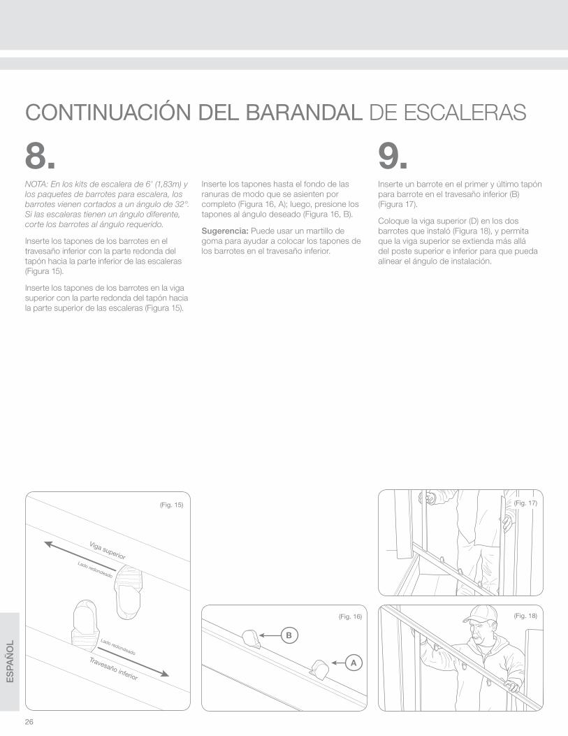
9.Inserte un barrote en el primer y último tapón
para barrote en el travesaño inferior (B)
(Figura 17).
Coloque la viga superior (D) en los dos
barrotes que instaló (Figura 18), y permita
que la viga superior se extienda más allá
del poste superior e inferior para que pueda
alinear el ángulo de instalación.
Bottom rail
Top beam
Rounded side
Rounded side
(Fig. 15)
B
A
8.NOTA: En los kits de escalera de 6' (1,83m) y
los paquetes de barrotes para escalera, los
barrotes vienen cortados a un ángulo de 32°.
Si las escaleras tienen un ángulo diferente,
corte los barrotes al ángulo requerido.
Inserte los tapones de los barrotes en el
travesaño inferior con la parte redonda del
tapón hacia la parte inferior de las escaleras
(Figura 15).
Inserte los tapones de los barrotes en la viga
superior con la parte redonda del tapón hacia
la parte superior de las escaleras (Figura 15).
Inserte los tapones hasta el fondo de las
ranuras de modo que se asienten por
completo (Figura 16, A); luego, presione los
tapones al ángulo deseado (Figura 16, B).
Sugerencia: Puede usar un martillo de
goma para ayudar a colocar los tapones de
los barrotes en el travesaño inferior.
Viga superior
Travesaño inferior
Lado redondeado
Lado redondeado
CONTINUACIÓN DEL BARANDAL DE ESCALERAS

ES
PA
ÑO
L
27
(Fig. 22) (Fig. 24)
11.Envuelva los soportes en sufi ciente cantidad
de cinta adhesiva como para que se deslice
perfectamente en los extremos de la viga.
Deslice los soportes hasta los extremos de
la viga superior. Alinee los soportes con el
ángulo marcado en la viga (Figura 21) de
modo que cuando realice el corte, lo haga
de tal manera que corte toda la cara del
soporte pero elimine tan poco material como
sea posible. Con los soportes fi jos en la
viga superior, corte a través de la viga y el
soporte en la línea marcada (Figura 22) para
establecer el ángulo de instalación.
12.Instale los tornillos de ajuste únicamente en la
parte interior del travesaño, y compruebe que
los tornillos de ajuste conecten la viga con el
soporte. Fije en el lugar que se muestra en la
Figura 22; esto debe ser lo más cerca posible
a la cara interior del soporte de tal manera
que el tornillo quede embebido, como se hizo
en la viga inferior.
Una vez en su lugar, inserte el resto de los
barrotes en los tapones en el travesaño inferior
(B) (Figura 24). Pegue los tres barrotes en
la parte intermedia del tramo de travesaño
en los tapones usando el pegamento PVC
suministrado. Coloque el pegamento en el
interior del barrote, y a continuación coloque el
barrote sobre el tapón para pegarlo en su lugar.
(Fig. 21)
(Fig. 23)
Sujete los tornillos de ajuste aquí
(Fig. 19)
(Fig. 20)
10.Ahora, ajuste la viga superior hasta que los
barrotes estén aplomados (Figura 19). Marque
ambos extremos de la viga superior (D) en la
cara interior del poste en donde se montará
(Figura 20). Ahora retire la viga superior.
Parte superior de escalera
Parte inferior de escalera
ES
PA
ÑO
L
28
(Fig. 28)
(Fig. 30)
(Fig. 29)
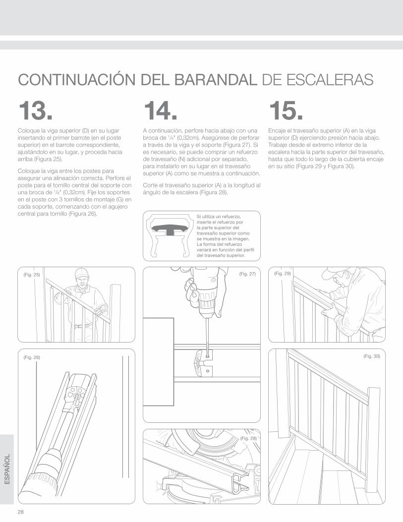
14.A continuación, perfore hacia abajo con una
broca de 1/8" (0,32cm). Asegúrese de perforar
a través de la viga y el soporte (Figura 27). Si
es necesario, se puede comprar un refuerzo
de travesaño (N) adicional por separado,
para instalarlo en su lugar en el travesaño
superior (A) como se muestra a continuación.
Corte el travesaño superior (A) a la longitud al
ángulo de la escalera (Figura 28).
15.Encaje el travesaño superior (A) en la viga
superior (D) ejerciendo presión hacia abajo.
Trabaje desde el extremo inferior de la
escalera hacia la parte superior del travesaño,
hasta que todo lo largo de la cubierta encaje
en su sitio (Figura 29 y Figura 30).
(Fig. 25)
(Fig. 26)
13.Coloque la viga superior (D) en su lugar
insertando el primer barrote (en el poste
superior) en el barrote correspondiente,
ajustándolo en su lugar, y proceda hacia
arriba (Figura 25).
Coloque la viga entre los postes para
asegurar una alineación correcta. Perfore el
poste para el tornillo central del soporte con
una broca de 1/8" (0,32cm). Fije los soportes
en el poste con 3 tornillos de montaje (G) en
cada soporte, comenzando con el agujero
central para tornillo (Figura 26).
(Fig. 27)
Si utiliza un refuerzo, inserte el refuerzo por la parte superior del travesaño superior como se muestra en la imagen. La forma del refuerzo variará en función del perfi l del travesaño superior.
CONTINUACIÓN DEL BARANDAL DE ESCALERAS

ES
PA
ÑO
L
29
Formula 409® es una marca comercial registrada de la The Clorox Company
Glass Plus® es una marca comercial registrada utilizada bajo la autoridad de Reckitt
Benckiser, LLC.
Comet®, Mr. Clean®, y Spic and Span® son marcas comerciales registradas de la empresa
Procter and Gamble
Soft Scrub® es una marca comercial registrada de Henkel Consumer Goods, Inc.
En general, se pueden utilizar los siguientes productos químicos de manera segura con el sistema de barandal Transform con recubrimiento acrílico a condiciones de temperatura ambiente:
• Limpiador Formula 409®
• Limpiador Glass Plus®
• Limpiador Liquid Comet®
• Aceite mineral
• Limpiador Mr. Clean®
• Jabón y agua
• Limpiador Soft Scrub®
• Limpiador Spic and Span®
16.Con los tornillos pintados (J), instale dos
de los tornillos hacia arriba desde la parte
inferior de cada extremo a través de los
agujeros perforados. Esto fi jará el soporte, la
viga y el travesaño superior (Figura 31).
(Fig. 31)
Las resinas acrílicas de recubrimiento tiene una buena resistencia a una gran variedad de limpiadores comunes y condiciones climatológicas. Se recomienda que pruebe todo limpiador en un área discreta antes de limpiar el sistema de barandal Transform. Se deben tomar precauciones de seguridad adecuadas y seguir las instrucciones del fabricante cuando se trabaja con cualquier agente químico. Deseche correctamente los productos químicos de acuerdo con el reglamento de eliminación de desechos químicos de la municipalidad local.
Mr. Clean® Magic Erasers® (estilo original) son el método recomendado de limpieza para todo producto de barandal Transform de cualquier color.
Cuidado y mantenimiento
ES
PA
ÑO
L
30
Railing Dynamics, Inc. (“RDI”) garantiza al consumidor o comprador original (el “Comprador”) los barandales RDI de vinilo rígido y Resalite™ y
los productos accesorios (el “Producto”) que permanecerán libres de defectos de materiales y mano de obra y que los materiales no se van a
descarapelar, podrir, oxidar o sufrir daños estructurales debido a las condiciones climatológicas, deterioro por hongos o insectos xilófagos, sujeto a
las siguientes limitaciones, exclusiones y condiciones durante los períodos de tiempo defi nidos a continuación:
1. Los periodos de la garantía a continuación son a partir de la fecha de compra original del producto:
a. Para toda la vida para propietarios individuales de su lugar de residencia (donde el producto se instaló originalmente)
b. 20 años, en usos de carácter comercial o gubernamental
c. Todos los colores excepto el blanco: 20 años para propietarios individuales de su lugar de residencia y en uso comercial y gubernamental
2. Esta garantía cubre el producto únicamente si fue comprado y utilizado exclusivamente en América del Norte.
3. Esta garantía podrá ser transferida en una ocasión, en un plazo de cinco años a partir de la fecha de compra original del producto, a un comprador
subsiguiente de la propiedad en el que el producto fue instalado originalmente. Como condición de la efi cacia de dicha transferencia, el cesionario
deberá enviar notifi cación escrita a RDI (en la dirección indicada anteriormente) de la transferencia, junto con la información sufi ciente para RDI para
determinar que la transferencia es válida de acuerdo con los términos de esta garantía, en un plazo de 30 días a partir de la supuesta transferencia.
No hay otra forma de transferencia o cesión de esta garantía que sea válida, y cualquier supuesta transferencia o cesión de derechos en virtud de
esta garantía anulará esta garantía.
4. Para presentar una reclamación bajo esta garantía, el comprador debe enviar a RDI, a la dirección proporcionada, por escrito durante el periodo de
la garantía, una notifi cación bastante detallada por escrito de cualquier defecto, daño u otro fallo del producto en un plazo de tiempo razonable después
del descubrimiento del motivo de la reclamación. RDI podrá exigir un comprobante de compra, el número de serie del producto, una fotografía clara de
la pieza defectuosa y la pieza misma. Si RDI determina que el comprador tiene una reclamación válida en virtud de esta garantía, RDI, a su discreción,
podrá: (i) enviar al comprador (a su dirección indicada en el formulario de registro de la garantía) el reemplazo de la pieza objeto de la reclamación de
garantía, de forma gratuita para el comprador (pero la pieza de recambio puede variar en color o acabado como resultado del desgaste o decoloración
normal del producto original o los cambios en las ofertas de RDI en colores y acabados); (ii) reparar o restaurar la pieza objeto de la reclamación de
garantía, de forma gratuita para el comprador, siempre que el comprador proporcione toda cooperación razonable; o (iii) enviar un pago al comprador
de la parte del precio de compra pagado por el comprador a RDl para la pieza objeto de la reclamación de garantía. Este párrafo prevé la compensación
exclusiva del comprador en virtud de esta garantía. Bajo ninguna circunstancia será responsable RDI de la instalación, remoción o reinstalación del
producto o de cualquiera de sus partes, o del costo de mano de obra, pérdida de tiempo, mantenimiento o inconveniencia.
5. Esta garantía no cubre el desgaste o la decoloración normal de las superfi cies debido a la exposición a la luz ultravioleta (por ejemplo, la luz del
sol) o las condiciones extremas de temperatura o presión. Esta garantía no cubre defectos, daños o fallos derivados o relacionados con el impacto
de un objeto extraño, granizo, vientos fuertes, inundaciones, terremotos, tormentas eléctricas u otros trastornos climáticos, incendios, actos de Dios,
contaminantes, productos químicos, residuos, materiales peligrosos o cualquier otra causa más allá del control de RDI.
6. ESTA GARANTÍA NO SE APLICA A, Y BAJO NINGUNA CIRCUNSTANCIA SERÁ RESPONSABLE RDI DE DEFECTOS, DAÑOS O FALLOS DERIVADOS
O RELACIONADOS CON EL USO INDEBIDO, ABUSO, NEGLIGENCIA, INSTALACIÓN DEFECTUOSA O INCORRECTA, O EL INCUMPLIMIENTO DE
CUALQUIER INSTRUCCIÓN O RECOMENDACIÓN DE LAS INSTRUCCIONES DE INSTALACIÓN DE RDI INCLUIDAS CON EL PRODUCTO (LAS
“INSTRUCCIONES DE INSTALACIÓN”). ESTA GARANTÍA SERÁ NULA SI LA SUPERFICIE DEL PRODUCTO ESTÁ CUBIERTA DE GRASA, ACEITE,
ÁCIDO O DE CUALQUIER OTRA MATERIA EXTRAÑA, EXCEPTO POR LO QUE SE RECOMIENDA EN LAS INSTRUCCIONES DE INSTALACIÓN.
ESTA GARANTÍA SERÁ NULA SI CUALQUIER PARTE DE ESTE PRODUCTO SE MODIFICA, O SI UTILIZA CUALQUIER PARTE ESTRUCTURAL O
UN COMPONENTE NO SUMINISTRADO POR RDI EN COMBINACIÓN CON EL PRODUCTO, EXCEPTO POR EL USO ADECUADO DE VIGUETAS
PARA TERRAZA U OTRAS ESTRUCTURAS DE APOYO DE ACUERDO CON LAS INSTRUCCIONES DE INSTALACIÓN. ESTA GARANTÍA NO
CUBRIRÁ NINGUNA CONSECUENCIA DE CUALQUIER DEFECTO O DAÑO A O EL FALLO DE CUALQUIERA DE VIGUETA DE TERRAZA U OTRAS
ESTRUCTURAS DE APOYO (O CUALQUIER COMPONENTE DE ESTOS). ESTA GARANTÍA SERÁ NULA SI EL PRODUCTO ES UTILIZADO EN
VIOLACIÓN DE CUALQUIER CÓDIGO DE CONSTRUCCIÓN, ORDENANZA DE ZONIFICACIÓN, ORDEN DEL JEFE DE BOMBEROS O CUALQUIER
OTRA LEY, REGLAMENTO, ORDEN, NORMA, DIRECTRIZ O RECOMENDACIÓN DE UN ÓRGANO JUDICIAL O GUBERNAMENTAL.
7. RDI NO GARANTIZA LA RESISTENCIA AL DESLIZAMIENTO DEL PRODUCTO. RDI NO TENDRÁ RESPONSABILIDAD ALGUNA EN CASO DE
DESLIZAMIENTOS O CAÍDAS SOBRE O DEL PRODUCTO. BAJO NINGUNA CIRCUNSTANCIA, RDI SERÁ RESPONSABLE DE DAÑOS A LA
PROPIEDAD, LESIONES PERSONALES O MUERTE.
8. BAJO NINGUNA CIRCUNSTANCIA, RDI SERÁ RESPONSABLE DE DAÑOS CONSECUENCIALES, INCIDENTALES, ESPECIALES, EJEMPLARES
O PUNITIVOS, Y EN NINGÚN CASO LA RESPONSABILIDAD DE RDI RELACIONADA CON CUALQUIER PRODUCTO O PARTE EXCEDERÁ EL
PRECIO DE COMPRA PAGADO POR EL COMPRADOR A RDI DE TAL PRODUCTO O PARTE. Algunos estados no permiten la exclusión o limitación
de daños consecuenciales o incidentales, por lo que la frase anterior puede no ser aplicable al comprador en dichos estados.
9. Salvo lo dispuesto expresamente en esta garantía, todos los compradores de este producto se realizan “TAL COMO ESTÁ, Y CON TODOS SUS
FALLOS” y sin ninguna representación, garantía, promesa o aseguranza de ningún tipo, expresa, implícita o estatutaria. Salvo lo dispuesto expresamente
en esta garantía, RDI EXPRESAMENTE NIEGA CUALQUIER REPRESENTACIÓN, GARANTÍA, PROMESA O ASEGURANZA DE NINGÚN TIPO, EXPRESA
O IMPLÍCITA, DE FORMA ORAL O ESCRITA, ESTATUTARIA O DE OTRO TIPO, RELACIONADA CON EL PRODUCTO, INCLUYENDO, ENTRE OTROS,
LA COMERCIABILIDAD, LA IDONEIDAD PARA CUALQUIER PROPÓSITO (OTRO DE LOS USOS DIRIGIDOS EXPRESAMENTE O RECOMENDADOS
EN LAS INSTRUCCIONES DE INSTALACIÓN), LA CALIDAD, LA FIABILIDAD, LA MANO DE OBRA, LOS MATERIALES, LA AUSENCIA DE DEFECTOS
(LATENTE O PATENTE), LA AUSENCIA DE CONDICIONES PELIGROSAS, LA CORRESPONDENCIA DE CUALQUIER DESCRIPCIÓN O SIMILARES.
NO HAY NINGÚN DISTRIBUIDOR, CONCESIONARIO U OTRA PERSONA QUE ESTÉ AUTORIZADO POR RDI PARA CAMBIAR ESTA GARANTÍA O A
HACER CUALQUIER OTRA REPRESENTACIÓN, GARANTÍA, PROMESA O ASEGURANZA EN NOMBRE DE RDI RELACIONADA CON EL PRODUCTO.
Para comenzar la cobertura de la garantía, complete el formulario de la derecha y envíelo por correo a:
GARANTÍA
Railing Dynamics, Inc.135 Steelmanville RoadEgg Harbor Township, NJ 08234
O BIEN
Registre el producto en línea en: www.rdirail.com/warranty

ES
PA
ÑO
L
31
Complete sólo un registro por instalación o producto. En la compra de varios productos, complete una tarjeta de garantía y enumere los números de serie
de los productos restantes. POR FAVOR, COMPLETE SU REGISTRO DENTRO DE LOS TREINTA (30) DÍAS DESPUÉS DE LA COMPRA.
Nombre del cliente:
Dirección:
Ciudad: Estado: Código postal:
Dirección electrónica:
Nombre del proveedor: Ciudad:
Fecha de compra: / / Fecha de instalación: / /
Firma del cliente Fecha
REGISTRO DEL PROPIETARIOREGISTRE EL PRODUCTO EN LÍNEA EN: WWW.RDIRAIL.COM/WARRANTY O
ES
CR
IBIR
CO
N L
ET
RA
DE
MO
LD
E
Línea de productos
Titan Pro Endurance Transform RDI Metal Works Excalibur RDI Metal Works Avalon Vinyl Hand Rail Aluminum Hand Rail
Color del producto
Blanco o Blanco satinado Tierra Sahara Negro o Negro satinado Bronce Ironstone Trigo Caramelo
¿Ha instalado este producto usted mismo?
Sí No En caso negativo, ¿quién fue su instalador?_________________________________________________________________________
¿Dónde está instalado este producto?
Casa Negocio Terraza delantera Terraza/porche trasero
¿Qué tipo de poste se utilizó para esta instalación?
Funda de vinilo en madera Funda de vinilo sobre poste estructural Poste de metal Poste de madera
¿En qué tipo de terraza está instalado el barandal?
Madera Compuesto Concreto Si es de madera o compuesto, ¿de qué color?_____________________________________________
¿Por qué medio se enteró de RDI?
Vendedor de tienda Exhibidor Feria comercial Revista Internet Remisión Otro _______________
¿Cuáles son las fuentes de información que utilizó para elegir nuestro producto?
Folleto Personal de ventas Sitio web Exhibidor Otro _______________
Por favor califique la calidad de su experiencia con:
Instrucciones Claras y fáciles de seguir Comprensibles Difíciles y confusas
Instalación Sencilla
Por favor, enumere otras sugerencias o ideas para productos y servicios de RDI:
_________________________________________________________________________________________________________________________
_________________________________________________________________________________________________________________________
Por favor, enumere todos los números de serie de los productos:
COMPLETE Y ENVÍE ESTE FORMULARIO PARA REGISTRAR LA GARANTÍA DEL PRODUCTO
Algo fácil, pero me alegro de haber
tenido las instrucciones
Me sentí como si estuviera tratando
de construir una nave espacial

32
RAILING DYNAMICS, INC.
FOR HOME, FOR LIFE®
135 STEELMANVILLE ROAD
EGG HARBOR TOWNSHIP, NJ 08234
TEL: (877) 420-7245
FAX: (866) 277-5160
E-MAIL: [email protected]
URL: WWW.RDIRAIL.COM
34107251
REV. 1.15
Need a little help installing your railing?Avez-vous besoin d’un peu d’aide pour installer votre rampe?
¿Necesita un poco de ayuda para instalar el barandal?www.rdirail.com/support/installation-videos.html
®