ENGLISH TRIF 21e 100105 - · PDF fileAccording to IEC 72-1, the following tolerances on...
61
Electric Motors Asynchronous three-phase motors 2005 Technical Catalogue 2.1e
-
Upload
phungkhanh -
Category
Documents
-
view
222 -
download
4
Transcript of ENGLISH TRIF 21e 100105 - · PDF fileAccording to IEC 72-1, the following tolerances on...

Electric Motors
Asynchronous three-phase motors
2005Technical Catalogue2.1e

AEG Electric Motors - 2.1 e/2005 - page 2
All technical data, outputs, dimensions and weights stated in this catalogue are subject tochange without prior notice.
The illustrations are not binding.

AEG Electric Motors - 2.1 e/2005 - page 3
Page
Standard quality . . . . . . . . . . . . . . . . . . . . . . . . . . . . . . . . . . . . . . . . . . . . . . . . . . . . . . . 5
Standards and regulations . . . . . . . . . . . . . . . . . . . . . . . . . . . . . . . . . . . . . . . . . . . . . . 6
Conditions of installation . . . . . . . . . . . . . . . . . . . . . . . . . . . . . . . . . . . . . . . . . . . . . . . . 8Permissible temperature rises . . . . . . . . . . . . . . . . . . . . . . . . . . . . . . . . . . . . . . . 8Tolerances . . . . . . . . . . . . . . . . . . . . . . . . . . . . . . . . . . . . . . . . . . . . . . . . . . . . 10
Mechanical designDegrees of protection . . . . . . . . . . . . . . . . . . . . . . . . . . . . . . . . . . . . . . . . . . . 11Mounting arrangements . . . . . . . . . . . . . . . . . . . . . . . . . . . . . . . . . . . . . . . . . 12Terminal boxes . . . . . . . . . . . . . . . . . . . . . . . . . . . . . . . . . . . . . . . . . . . . . . . . . 13Materials . . . . . . . . . . . . . . . . . . . . . . . . . . . . . . . . . . . . . . . . . . . . . . . . . . . . . 15Paint finish . . . . . . . . . . . . . . . . . . . . . . . . . . . . . . . . . . . . . . . . . . . . . . . . . . . . 15Bearings. . . . . . . . . . . . . . . . . . . . . . . . . . . . . . . . . . . . . . . . . . . . . . . . . . . . . . 16Belt drive . . . . . . . . . . . . . . . . . . . . . . . . . . . . . . . . . . . . . . . . . . . . . . . . . . . . . 19Lubrication and maintenance of bearings. . . . . . . . . . . . . . . . . . . . . . . . . . . . . 20Lubricating nipples . . . . . . . . . . . . . . . . . . . . . . . . . . . . . . . . . . . . . . . . . . . . . . 20Cooling . . . . . . . . . . . . . . . . . . . . . . . . . . . . . . . . . . . . . . . . . . . . . . . . . . . . . . 20Vibration . . . . . . . . . . . . . . . . . . . . . . . . . . . . . . . . . . . . . . . . . . . . . . . . . . . . . 20Anti-condensation heater. . . . . . . . . . . . . . . . . . . . . . . . . . . . . . . . . . . . . . . . . 21Noise . . . . . . . . . . . . . . . . . . . . . . . . . . . . . . . . . . . . . . . . . . . . . . . . . . . . . . . . 22Spare parts. . . . . . . . . . . . . . . . . . . . . . . . . . . . . . . . . . . . . . . . . . . . . . . . . . . . 23
Electrical designRated voltage. . . . . . . . . . . . . . . . . . . . . . . . . . . . . . . . . . . . . . . . . . . . . . . . . . 24Rated frequency. . . . . . . . . . . . . . . . . . . . . . . . . . . . . . . . . . . . . . . . . . . . . . . . 24Rated current . . . . . . . . . . . . . . . . . . . . . . . . . . . . . . . . . . . . . . . . . . . . . . . . . . 25Rated torque . . . . . . . . . . . . . . . . . . . . . . . . . . . . . . . . . . . . . . . . . . . . . . . . . . 25Output. . . . . . . . . . . . . . . . . . . . . . . . . . . . . . . . . . . . . . . . . . . . . . . . . . . . . . . 25Overload . . . . . . . . . . . . . . . . . . . . . . . . . . . . . . . . . . . . . . . . . . . . . . . . . . . . . 25Connection . . . . . . . . . . . . . . . . . . . . . . . . . . . . . . . . . . . . . . . . . . . . . . . . . . . 25Connection diagrams . . . . . . . . . . . . . . . . . . . . . . . . . . . . . . . . . . . . . . . . . . . . 26Insulation and temperature rise . . . . . . . . . . . . . . . . . . . . . . . . . . . . . . . . . . . . 27Starting rate. . . . . . . . . . . . . . . . . . . . . . . . . . . . . . . . . . . . . . . . . . . . . . . . . . . 28Thermal protection. . . . . . . . . . . . . . . . . . . . . . . . . . . . . . . . . . . . . . . . . . . . . . 29Three-phase cage motors driven by frequency converter . . . . . . . . . . . . . . . . . 31
Order dataMotors for normal duty and conditions . . . . . . . . . . . . . . . . . . . . . . . . . . . . . . 33Additional information for special designs . . . . . . . . . . . . . . . . . . . . . . . . . . . . 33Special service duties . . . . . . . . . . . . . . . . . . . . . . . . . . . . . . . . . . . . . . . . . . . . 34
Type designation . . . . . . . . . . . . . . . . . . . . . . . . . . . . . . . . . . . . . . . . . . . . . . . . . . . . . . 35
Electrical data . . . . . . . . . . . . . . . . . . . . . . . . . . . . . . . . . . . . . . . . . . . . . . . . . . . . . . . . 36
Dimensions . . . . . . . . . . . . . . . . . . . . . . . . . . . . . . . . . . . . . . . . . . . . . . . . . . . . . . . . . . 52
Contents. . . . . . . . . . . . . . . . . . . . . . . . . . . . . . . . . . . . . . . . . . . . . . . . . . . . . . . . . . . . . . . . . . . . . . . . . . . . . . .

AEG Electric Motors - 2.1 e/2005 - page 4

AEG Electric Motors - 2.1 e/2005 - page 5
The strictness of our quality control assures the flawless operation and reliabilityof our products. That our quality scale fulfils your demands is confirmed by thecertificate awarded by the TÜV-CERT Certification body of TÜV Rheinland andthe CERMET, a Certification body authorized by SINCERT.
Standard Qual ity. . . . . . . . . . . . . . . . . . . . . . . . . . . . . . . . . . . . . . . . . . . . . . . . . . . . . . . . . . . . . . . . . . . . . . . . . . . . . . .

AEG Electric Motors - 2.1 e/2005 - page 6
Standards and regulations. . . . . . . . . . . . . . . . . . . . . . . . . . . . . . . . . . . . . . . . . . . . . . . . . . . . . . . . . . . . . . . . . . . . . . . . . . . . . . . .
CE Marking
Our three-phase induction motors comply with the requirements of the followinginternational standard:
IEC 60034
as well as with the Low Voltage Directive 73/23 (1973), modified by the Directive93/68 (1993) and the EMC-Directive 89/336.
The above named products comply with the requirements of the EC DirectiveMachines 89/392. In accordance with this Directive induction motors arecomponents and intended solely for integration into other machines.Commissioning is forbidden until conformity of the end product with thisDirective is proved!
The symbol was applied for the first time in 1995.
The safety instructions in the Operation Manual of the manufacturer andEN 60204-1 have to be observed.
CEMEP Voluntary Agreement
Motors covered by this agreement are defined as totally enclosed fan-cooled(normally IP 54 or IP 55), three-phase AC squirrel cage induction motors 1.1 to90 kW, with 2 or 4 poles, rated for 400 V-line, 50 Hz, duty class S1. (Standarddesign can be interpreted as design N according to EN 60034-12 and HD 231).They are divided in three classes of efficiency levels, defined by 2 values of fullload efficiency per output, designated eff1, eff2 and eff3.
All motors with standard rating included in this catalogue comply with efficiencyclass eff2 and bear the corresponding label on the rating plate. For efficiency dataat 50%, 75% and full load, please refer to the electrical data tables.

AEG Electric Motors - 2.1 e/2005 - page 7
Motors to special regulations:
• Motors to VIK regulations (German Society for Industrial Energy and PowerStations) to VIK recommendation Technical Requirements April 1999
• Motors with UL and/or CSA approval (performance data on request)• Motors with CULUS (CURUS) approval
The motors can furthermore be designed according to the stipulations forfloating installations of the most important classification societies. For furtherdetails see our technical catalogue Three-phase motors for marine applications.
The motors comply with the relevant standards and regulations, especially:
Títle EU D I GB F E
IEC CENELEC DIN/VDE CEI/UNEL BS NFC UNE
Electrical
General stipulations 60034-1 EN 60034-1 DIN EN 60034-1 CEI EN 60034-1 4999-1 51-200 UNE EN 60034-1
for electrical machines 4999-69 51-111
Rotating electrical machines: 60034-2 HD 53 2 DIN EN 60034-2 CEI EN 60034-2 4999-34 51-112 UNE EN 60034-2
methods for determining losses
and efficiency using tests
Terminal markings and 60034-8 HD 53 8 S4 DIN VDE 0530-8 CEI 2-8 4999-3 51-118 20113-8-96
direction of rotation of
rotating electrical machines
Starting performance 60034-12 EN 60034-12 DIN EN 60034-12 CEI EN 60034-12 4999-112 UNE EN 60034-12
Standard voltages 60038 HD 472 S1 DIN IEC 60038 CEI 8-6
Insulating materials 60085 DIN IEC 60085 CEI 15-26
Mechanical
Dimensions and output 60072 DIN EN 50347 UNEL 13113
ratings
Mounting dimensions and re- 60072 DIN 42673-1 UNEL 13113 4999-10 51-105 UNE EN 50347
lationship frame sizes-output 51-110 51-104 1980
ratings, IM B3
Mounting dimensions and re- 60072 DIN 42677-1 UNEL 13117 20106-2-74
lationship frame sizes-output
ratings, IM B5
Mounting dimensions and re- 60072 DIN 42677-1 UNEL 13118 4999-10 51-105 UNE EN 50347
lationship frame sizes-output 51-110 51-104
ratings, IM B14
Cylindrical shaft ends for 60072 HD 231 DIN 748-3 UNEL 13502 4999-10 51-111
electric motors
Degrees of protection 60034-5 EN 60034-5 DIN EN 60034-5 CEI EN 60034-5 4999-20 EN60034-5 20111-5
Methods of cooling 60034-6 EN 60034-6 DIN EN 60034-6 CEI EN 60034-6 4999-21 EN 60034-6
Mounting arrangements 60034-7 EN 60034-7 DIN EN 60034-7 CEI EN 60034-7 4999-22 51-117 EN 60034-7
Noise limits 60034-9 EN 60034-9 DIN EN 60034-9 CEI EN 60034-9 4999-51 51-119 EN 60034-9
Mechanical vibration 60034-14 EN60034-14 DIN EN 60034-14 CEI EN 60034-14 4999-50 51-111 EN 60034-14
Mounting flanges DIN 42948 UNEL 13501
Tolerances of mounting and DIN 42955 UNEL 13501/
shaft extensions 13502
Classification of 600721-2-1 DIN IEC 60721-2-1 CEI 75-1
environmental conditions
Mechanical vibration; ISO 8821 DIN ISO 8821
balancing

AEG Electric Motors - 2.1 e/2005 - page 8
Condit ions of instal lat ion. . . . . . . . . . . . . . . . . . . . . . . . . . . . . . . . . . . . . . . . . . . . . . . . . . . . . . . . . . . . . . . . . . . . . . . . . . . . . . . . .Condit ions of instal lat ion. . . . . . . . . . . . . . . . . . . . . . . . . . . . . . . . . . . . . . . . . . . . . . . . . . . . . . . . . . . . . . . . . . . . . . . . . . . . . . . . .
The motors are designed for operation at altitudes ≤ 1000 m above sea-level andat ambient temperatures of up to 40° C. Exceptions are indicated on the ratingplate.
1) Classification societies formarine motors
2) Only with special approval
Permissible temperature rises to various standards
Standard/Regulation Temperature Permissible temperature rise in Kof coolant (measured by resistance method)
Temperature class°C B F H
VDE 0530 part 1 40 80 105 125
International IEC 34-1 40 80 105 125
Britain BS 2613 40 80 105
Canada CSA 40 80 105
USA NEMA and ANSI 40 80 105
Italy CEI 40 80 105
Sweden SEN 40 80 105
Norway NEK 40 80 105
Belgium NBN 40 80 105
France NF 40 80 105
Switzerland SEV 40 80 105
India IS 40 80 -
Germanischer Lloyd 1) 45 75 90
American Bureau of Shipping 1) 50 70 95
Bureau Veritas 1) 45 70 100
Norske Veritas 1) 45 70 90 2)
Lloyds Register 1) 45 70 90
Registro Italiano Navale 1) 45 70 90
Korean Register 1) 50 70 90
China Classification Society 1) 45 75 95
onrequest

AEG Electric Motors - 2.1 e/2005 - page 9
The motors conform to degree of protection IP 55 to IEC 60034-5. Higherprotection on request.
The standard design for horizontal mounting is suitable for indoor and protectedoutdoor installation, climate group MODERATE (see page 15) (temperature ofcoolant -20° to +40° C).
For unprotected outdoor installation or severe climatic conditions (moisturecategory wet, climate group WORLDWIDE, extremely dusty site conditions,aggressive industrial atmosphere, danger of storm rain and coastal climate,danger of attack by termites, etc.), as well as vertical mounting, special protectivemeasures are recommended, such as:
• Protective cowl (for vertical shaft-down motors)• For vertical shaft-up motors additional bearing seal and flange drainage• Special paint finish• Treatment of winding with protective moisture-proof varnish• Anti-condensation heating (possibly winding heating)• Condensation drain holes
The special measures to be applied have to be agreed with the factory once theconditions of installation have been settled.
The corresponding conditions of installation have to be clearly indicated in the order.

AEG Electric Motors - 2.1 e/2005 - page 10
Tolerances
For industrial motors to EN 60034-1, certain tolerances must be allowed onguaranteed values, taking into consideration the necessary tolerances for themanufacture of such motors and the materials used. The standard includes thefollowing remarks:
1. It is not intended that guarantees necessarily have to be given for all orany of the items involved. Quotations including guaranteed values subjectto tolerances should say so, and the tolerances should be in accordancewith the table.
2. Attention is drawn to the different interpretation of the term guarantee.In some countries a distinction is made between guaranteed values andtypical or declared values.
3. Where a tolerance is stated in only one direction, the value is not limitedin the other direction.
Mechanical tolerances
According to IEC 72-1, the following tolerances on mechanical dimensions ofelectric motors are permitted:
Parameter Code Tolerances
Shaft length H - up to 250 -0,5 mm- over 250 -1 mm- from 11 to 28 mm j6
Diameter of shaft end D-DA - from 38 to 48 mm k6- from 55 to 100 mm m6
Hub key width F-FA h9Flange spigot N - up to 132 j6
- over size 132 h6
Note: The holes at the shaft end conform with DIN 332
Values for Tolerance
Efficiency (η) - 0.15 (1 - η) at PN ≤50 kW(by indirect determination) - 0.1 (1 - η) at PN > 50 kW
1 - cos ϕPower factor (cos ϕ) , minimum 0.02, maximum 0.07
6
Slip (s) ± 20 % of the guaranteed slip at PN ≥ 1 kW(at rated load and at working temperature) ± 30 % of the guaranteed slip at PN < 1 kW
Breakaway starting current (IA) + 20 % of the guaranteed starting current(in the starting circuit envisaged) (no lower limit)
Breakaway torque (MA) - 15 % and + 25 % of the guaranteed breakaway torque(+ 25 % may be exceeded by agreement)
Pull-up torque (MS) - 15 % of the guaranteed value
Pull-out torque (MK) - 10 % of the guaranteed value(after allowing for this tolerance, MK/MN not less than 1.6)
Moment of inertia (J) ± 10 % of the guaranteed value

AEG Electric Motors - 2.1 e/2005 - page 11
Mechanical design. . . . . . . . . . . . . . . . . . . . . . . . . . . . . . . . . . . . . . . . . . . . . . . . . . . . . . . . . . . . . . . . . . . . . . . . . . . . . . .
Degrees of protection
Degrees of protection for mechanical machines are designated in accordancewith IEC 60034-5 by the letters IP and two characteristic numerals.
Second numeral:Protection against ingress of water
First numeral: Protection against contactand ingress of foreign bodies
IP Description
0 No special protection
1 Protection against solid foreign bodies larger than 50 mm (Example: inadvertent contact withthe hand)
2 Protection against solid foreign bodies larger than 12 mm (Example: inadvertent contact withthe fingers)
3 Protection against solid foreign bodies larger than 2.5 mm (Example: Wires, tools)
4 Protection against solid foreign bodies larger than 1 mm (Example: Wires, bands)
5 Protection against dust (harmful deposits of dust)
6 Complete protection against dust. Is not described for electrical machines to IEC 34-5.
IP Description
0 No special protection
1 Protection against vertically falling water drops (condensation)
2 Protection against dropping waterwhen inclined by up to 15°
3 Protection against waterspray at up to 60° from vertical
4 Protection against water splashedfrom any direction
5 Protection against water projected by a nozzle from any direction
6 Protection against heavy seas or water projected in powerful jets
7 Protection when submerged between 0.15 and 1 m
8 Protection when continuously submerged in water at conditionsagreed between the manufacturer and the user.

AEG Electric Motors - 2.1 e/2005 - page 12
IM B3 (IM 1001)
IM B6 (IM 1051) *
IM B7 (IM 1061) *
IM B8 (IM 1071) *
IM V5 (IM 1011) *
IM V6 (IM 1031) *
Foot mounting Flange mounting Motors without endshield
IM B5 (IM 3001) Flange type A toDIN 42 948 at drive end
IM V1 (IM 3011) Flange type A toDIN 42 948 at drive end
IM V3 (IM 3031) Flange type A toDIN 42 948 at drive end
IM B35 (IM 2001) Flange type A toDIN 42 948 at drive end
IM B15 (IM 1201) without endshield and withoutball bearings on drive end
IM B9 (IM 9101) without endshield and withoutball bearings on drive end
IM V8 (IM 9111) without endshield and withoutball bearings on drive end
IM V9 (IM 9131) without endshield and withoutball bearings on drive end
IM B14 (IM 3601) Flange type C toDIN 42 948 at drive end
IM V18 (IM 3611) Flange type C toDIN 42 948 at drive end
IM V19 (IM 3631) Flange type C toDIN 42 948 at drive end
IM B34 (IM 2101) Flange type C toDIN 42 948 at drive end
* From frame size 225 on request
Mounting arrangements
Mounting arrangements for rotating electrical machines are designated accordingto IEC 60034-7, Code I (in brackets Code II).
Our motors are available with the mounting arrangements listed below,depending on design and frame size. Motors with aluminium frame are equippedwith removable feet that allow easy change of mounting arrangement.
It is essential to state the desired mounting arrangement when ordering,as the constructive design depends partly on the mounting arrangement.

AEG Electric Motors - 2.1 e/2005 - page 13
Terminal boxes
The location of the terminal box in standard design is on top; on the right or onthe left are possible.
For motors with mountings IM B6, IM B7, IM B8, IM V5, IM V6 the location ofthe terminal box is related to an IM B3 mounting.
The position of the entry openings can be adjusted to suit the existingconnection facilities by turning through 90°. Should special accessories be used(temperature detectors, anti-condensation heating, etc.) please enquire.
For motors in standard design, the cable gland does not belong to our scope ofdelivery.
For plastic terminal boxes, only plastic glands may be used (shock protection).
When using screened leads, a metal terminal box is required.
Direction of cable entries
Frame size Degree of Thread for cable Connection for Max. cable Terminal Max. externalprotection entry temperature section thread cable diam.
detectorPg 1) Metric 2) Pg 1) Metric 2) mm 2 mm
56 - 71 IP 55 1 x Pg 11 x Pg 13.5 1 x M16 x M20 - - 2.5 M4 12
80 IP 55 1 x Pg 13.5 x Pg 16 1 x M25 x M20 - - 2.5 M4 16
90-112 IP 55 1 x Pg 13.5 x Pg 16 1 x M25 x M20 - - 4 M5 16
132 IP 55 2 x Pg 21 2 x M32 - - 4 M5 20
160 IP 55 2 x Pg 29 2 x M40 Pg 11 M20 16 M6 28
180 IP 55 2 x Pg 29 2 x M40 Pg 13.5 M20 35 M8 28
200 IP 55 2 x Pg 36 2 x M50 Pg 16 M25 35 M8 34
225 IP 55 2 x Pg 36 2 x M50 Pg 16 M25 50 M10 34
250 - 280 IP 55 2 x Pg 42 2 x M63 Pg 16 M25 50 M10 40
315 IP 55 2 x Pg 48 3) 2 x M63 3) 2 x Pg 16 M25 185 M12 48
1) Pg thread to DIN 40 4302) Pitch 1.53) Terminal box with unscrewable cable entry plate
AEG Electric Motors - 2.1 e/2005 - page 14
Frame size h g4 A B Design Material
Standard design
56 98 91 93 Z K63 103 91 93 Z K71 112 91 93 Z K80 2) 129 111 116 Z K90 2) 138 111 116 Z K
100 2) 145 111 116 Z K112 2) 161 111 116 Z K132 198 133 133 Z AL160 246 149 149 Z AL180 266 204 180 Z SB200 341 258 265 Z SB225 360 258 265 Z SB250 390 258 265 Z SB280 423 258 265 Z SB315 515 400 285 Z GG
Frame size h g4 A B Design Material
Special design
56 100 94 94 Z AI63 105 94 94 Z AI71 114 94 94 Z AI80 139 110 110 Z AI90 148 110 110 Z AI
100 155 110 110 Z AI112 171 110 110 Z AI132 205 143 143 Z GG160 250 168 168 Z GG180 285 209 220 Z GG200 310 241 246 Z GG225 334 272 254 Z GG250 375 272 254 Z GG280 409 272 254 Z GG
Special design gland cover
56 64 70 70 E K63 69 70 70 E K71 78 70 70 E K80 125 3) 91 91 E AI90 137 3) 91 91 E AI
100 141 3) 91 91 E AI112 154 3) 91 91 E AI132 183 111 111 E GG160 225 130 130 E GG180 250 3) 144 144 E GG200 280 3) 172 172 E GG225 300 3) 172 172 E GG250 340 208 208 E GG280 375 208 208 E GG
Terminal box on top Terminal box at the side left 1) right
1) On frame size 56-71 the terminal box is supplied displaced towards the non-drive end
2) For metric thread, increase g4 by 6mm3) Maximum height with screw joint
B
A
g4
h
g4
h
A
B
Design: E = Single partZ = Two parts
Material: K = PlasticsSB = Sheet steelAL = AluminiumGG = Cast iron

AEG Electric Motors - 2.1 e/2005 - page 15
MaterialsMotor parts Frame size Material
Stator frame 56 - 180 Aluminium alloy
132 - 180 Cast iron (optional)
225 - 315 Cast iron
Endshield 56 - 112 Aluminium alloy
132 - 315 Cast iron
Flanged endshield 56 - 112 Aluminium alloy
132 - 315 Cast iron
Fan cover 56 - 63 Sheet steel
71 - 112 Plastics
80 - 112 Sheet steel (optional)
132 - 315 Sheet steel
Fan 56-315 Plastics
Terminal box 56 - 112 Plastics
56 - 112 Aluminium alloy (optional)
132 - 160 Aluminium alloy
180 - 280 + 315SY Sheet steel
315 Cast iron
Paint finish
Normal finishSuitable for climate group Moderate to DIN 600 721-2-1, e.g. indoor andoutdoor installationfor short periods: up to 100 % rel. humidity at temperatures up to +30° Ccontinuously: up to 85 % rel. humidity at temperatures up to +25° C
Special finish K1Suitable for climate group Worldwide to DIN 600 721-2-1, e.g. outdoorinstallation in corrosive chemical and marine atmospheresfor short periods: up to 100 % rel. humidity at temperatures up to +35° Ccontinuously: up to 98 % rel. humidity at temperatures up to +30° C
Special finishes (on request)• Special finish K2 (additional treatment of internal motor parts)• Special paint for exposure to the action of alkalis• Special finishes to customers’ requirements

AEG Electric Motors - 2.1 e/2005 - page 16
Bearings
Classification of bearings (standard design) 1)
Ball bearings to ISO15 (DIN 625)
Bearing arrangement (AM, AMV)
Frame size Bearing drive end Bearing non-drive end Spring-loaded
56 - 112 Non-locating bearing Non-locating bearing Non-drive end132 - 280 Locating bearing Non-locating bearing Non-drive end315 Non-locating bearing Locating bearing Drive end
1) In frame sizes 132 to 280 bearings type 63 also possible at drive and non-drive end (preferably locating bearing non-drive end), or bearings NU 3 at drive
end in frame sizes 160 to 280 (only locating bearing at non-drive end).2) IM B14 bearing drive end 6309-2Z C3
Frame size No. of Drive end Non-drive endpoles
160 2) 2 - 8 6209-2Z C3 6209-2Z C3180 2 - 8 6210-2Z C3 6210-2Z C3200 2 - 8 6212-2Z C3 6212-2Z C3225 2 - 8 6213-Z C3 6213-Z C3250 2 - 8 6214 C3 6214 C3280 2 - 8 6216 C3 6216 C3315 2 6316 C3 6316 C3
4 - 8 6319 C3 6319 C3315SY 4 - 8 6319 C3 6316 C3
Maximum permissible axial forces without additional radial forces *
Frame Horizontal shaft Vertical shaft - force upwards Vertical shaft - force downwards size 3000 1500 1000 750 3000 1500 1000 750 3000 1500 1000 750
min -1 min -1 min -1 min -1 min -1 min -1 min -1 min -1 min -1 min -1 min -1 min -1
kN kN kN kN kN kN kN kN kN kN kN kN
56 0.16 0.21 - - 0.18 0.22 - - 0.15 0.19 - -63 0.19 0.26 - - 0.21 0.28 - - 0.17 0.24 - -71 0.23 0.33 0.33 0.37 0.26 0.35 0.36 0.39 0.21 0.30 0.31 0.3480 0.32 0.44 0.46 0.50 0.34 0.47 0.48 0.53 0.29 0.41 0.43 0.4790 0.34 0.48 0.49 0.54 0.38 0.47 0.53 0.58 0.31 0.44 0.46 0.51
100 0.48 0.68 0.70 0.77 0.54 0.74 0.76 0.83 0.43 0.62 0.64 0.71112 0.48 0.68 0.70 0.77 0.56 0.75 0.77 0.84 0.40 0.60 0.62 0.69132 0.6 0.9 1.1 1.3 1.0 1.3 1.5 1.9 0.5 0.75 0.75 1.05160 0.5 0.8 1.2 1.5 1 1.4 1.8 2 0.2 0.4 0.6 0.9180 0.5 0.8 1.2 1.5 1.1 1.4 1.8 2.1 0.2 0.4 0.6 0.9200 0.8 1.3 1.5 1.8 1.8 2.3 2.5 2.8 0.2 0.7 0.9 1.1225 1.0 1.6 1.9 2.4 2.1 2.6 2.9 3.4 0.3 0.70 1.0 1.5250 1.1 1.6 2.0 2.5 2.3 2.7 3.2 3.7 0.2 0.60 1.1 1.5280 1.7 1.9 2.4 2.9 2.9 3.1 3.6 3.7 0.15 0.3 0.8 1.0315 3.5 4.0 4.5 5.0 6.0 7.0 7.5 8.0 1.0 1.9 2.4 2.9
Values for 50 Hz. For service on 60 Hz, reduce values by 10%
* Consult according to direction of force
Frame size No. of Drive end Non-drive endpoles
56 2 + 4 6201-2Z 6201-2Z 63 2 + 4 6202-2Z 6202-2Z71 2 - 8 6202-2Z 6202-2Z80 2 - 8 6204-2Z C3 6204-2Z C390 2 - 8 6205-2Z C3 6205-2Z C3100 2 - 8 6206-2Z C3 6206-2Z C3112 2 - 8 6306-2Z C3 6306-2Z C3132 2 - 8 6208-2Z C3 6208-2Z C3

AEG Electric Motors - 2.1 e/2005 - page 17
AM 132
3000
1500
1000
750 1/min
0 40 80 mm 120x
3.0
kN
2.6
2.2
1.8
1.4
1.0
FR
AM 250
0 60 120 mm 180x
6
kN
5
4
3
2
1
FR
1000
3000
1500
750 1/min
3000
1500
1000
750 1/min
AM 280
0 60 120 mm 180x
6
kN
5
4
3
2
1
FR
AM 225
0 60 120 mm 180x
6
kN
5
4
3
2
1
FR
750 1/min1000
1500
3000
3000
1000
AM 160
0 40 80 mm 120x
3.0
kN
2.6
2.2
1.8
1.4
1.0
FR
1500
750 1/min
3000
1500
1000
0 40 80 mm 120x
3.0
kN
2.6
2.2
1.8
1.4
1.0
FR
AM 180
750 1/min
0 40 80 mm 120x
6
kN
5
4
3
2
1
AM 200
3000
1500
1000
750 1/min
FR
0 60 120 mm 180x
12
kN
10
8
6
4
2
FR
AM 315
3000
1500
1000
750 1/min
Permissible radial forces without additional axial force(Ball bearings)
Nominal life = 20.000 h (Lh10)
FR = permissible radial force in kN
X = Distance between point of application of force and shaft shoulder (e.g. half pulley width)
Size FR in N when 2p=2 4 6 8
56 340 428 - -63 385 485 - -71 463 583 668 73580 590 830 860 945
90SL 675 940 975 1070100L 925 1295 1335 1470
112M 930 1300 1340 1476

AEG Electric Motors - 2.1 e/2005 - page 18
0 60 120 mm 180x
14
kN
12
10
8
6
4
FR
AM 280
1000 1/min
1500
750
0 40 80 mm 120x
0 60 120 mm 180x
10
kN
9
8
7
6
5
FR
AM 250
750,10001/m
in1500
3.6
kN
3.2
2.8
2.4
2.0
1.6
FR
AM 160
1500,1000,7501/m
in
AM 180
0 40 80 mm 120x
10
kN
8
6
4
2
0
FR
AM 200
7501/m
in1000, 1500
0 40 80 mm 120x
6
kN
5
4
3
2
1
FR
1500,1000,750 1/min
0 60 120 mm 180x
10
kN
8
6
4
2
0
FR
AM 225
1500,1000,7501/m
in
AM 315
1500
1000
750 1/min
0 60 120 mm 180x
22
kN
18
14
10
6
2
FR
Reinforced bearings (special design)Roller bearings to DIN 5412
Frame size No. of Drive end Non-drive endpoles
160 2 - 8 NU 209 E 6209-2Z C3180 2 - 8 NU 210 E 6210-2Z C3200 2 - 8 NU 212 E 6212-2Z C3225 2 - 8 NU 213 E 6213-Z C3
Frame size No. of Drive end Non-drive endpoles
250 2 - 8 NU 214 E 6214 C3280 2 - 8 NU 216 E 6216 C3315 2 NU 316 E 6316 C3
4 - 8 NU 319 E 6319 C3315SY 4 - 8 NU 319 E 6316 C3
The modification from standard design to roller bearings is not possible, except for frame size 315.
Permissible radial forces without additional axial forces(Roller bearings)
FR = permissible radial force in kN
X = Distance between point of application of force andshaft shoulder (e.g. half pulley width)

AEG Electric Motors - 2.1 e/2005 - page 19
*not interchangeable with standard motors
Belt drive
The data apply only to the normal drive end shaft extension of IM B3 motorswith one speed.
Calculation of belt drive:
19120 · P ·kFR =
D1 · n
FR = Radial shaft load in NP = Output in kWn = Speed in min-1
D1 = Pulley diameter in mk = Belt tension factor, varying with the type of belt, assumed to be
approximately:3-4 for normal flat belt without idler pulley2-2.5 for normal flat belt with idler pulley2.2-2.5 for V-beltFor exact data apply to the belt manufacturer.
Special bearings and flanges
Frame size IM B3 / IM B5 IM B14 IM B5Oversized Oversized Reducedbearing bearing flange
132 6308 - A250*
160 6309 C250-6309 A300
180 6310 - A300
200 6312 - A350*
225 6313 - A400
250 6314 - A450
280 6316 - A450*
315 - - -

AEG Electric Motors - 2.1 e/2005 - page 20
Lubrication and maintenance of bearings
Bearings of standard motors up to frame size 250 have permanent lubrication.Bearing grease K3N to DIN 51 825 (e.g. KLÜBER ASONIC GHY72, ESSO UNIREXN3 or similar) is used.
Maintenance-free life for motors with permanent lubrication at ambienttemperature of 40° C and service at 50 Hz:
2 and 4/2 pole motors 10,000 h4 and more pole motors 20,000 h, but not more than 4 years.
From frame size 280 upwards the motors are equipped with regreasing deviceand grease slinger (possible from frame size 160 at extra cost).
First lubrication is made with grease K3N to DIN 51 825 (lithium-based, waterresistant to DIN 51 807 part 1: grade 0 or 1).
For motors with regreasing device, regreasing interval and required quantity ofgrease is indicated on the nameplate.
For regreasing please observe the Operating Instructions.
Where unfavourable conditions prevail (e.g. high ambient temperature, dustyconditions, corrosive atmosphere, operation by frequency converter), relubricationshould be carried out more frequently.
Lubricating nipples
Flat lubricating nipples M 10x1 to DIN 3404.
Vibration
The amplitude of vibration in electric motors is governed by EN 60034-14Mechanical vibration of rotating electrical machines with shaft heights 56 and larger - methods of measurement and limits.
Standard motors are designed to vibration grade A (normal). Vibration grade B are available at extra cost.
Pole-changing motors in Dahlander connectioncan only be supplied in vibration grade A.
Rotors are at present dynamically balanced with half key fitted as per DIN ISO 8821.Other balancing only on request.
The motors are identified as follows:
"H" or "blank" means balanced with half key"F" means balanced with full key"N" means no key
Cooling
Surface cooling, independent of the direction of rotation.
Motors type AM available without internal fan as type AG, e.g. for installation ina directed air stream (outputs on request).

AEG Electric Motors - 2.1 e/2005 - page 21
Anti-condensation heater
On request, motors which due to strong temperature fluctuations are exposedto condensation during standstill, can be fitted against surcharge with an anti-condensation heater (space heater).
For supply voltage and heater rating please refer to the following table:
Frame size Supply voltage (V) Heater rating per motor (W)
112 - 160 110 or 230 40180 - 225 “ 50250 - 280 “ 65
315 “ 99
During operation of the motor, the heating must be switched off.
Frame size d x l1 b x h l2 l3 t56 9 x 20 3 x 3 15 2.5 10.263 11 x 23 4 x 4 15 4 12.571 14 x 30 5 x 5 20 5 1680 19 x 40 6 x 6 30 6 21.590 24 x 50 8 x 7 40 6 27100 28 x 60 8 x 7 50 6 31112 28 x 60 8 x 7 50 6 31132 38 x 80 10 x 8 70 5 41160 42 x 110 12 x 8 100 5 45180 48 x 110 14 x 9 100 5 51.5200 55 x 110 16 x 10 100 5 59225 2 poles 55 x 110 16 x 10 100 5 59225 4 poles 60 x 140 18 x 11 110 10 64250 2 poles 60 x 140 18 x 11 110 10 64250 4 poles 65 x 140 18 x 11 110 10 69280 2 poles 65 x 140 18 x 11 100 10 69280 4 poles 75 x 140 20 x 12 100 10 79.5315 2 poles 65 x 140 18 x 11 125 7.5 69315 4 poles 80 x 170 22 x 14 140 10 85
Dimensions in mmFor larger shafts in special design the dimensions l2 and l3 are maintained.
l2
d
l1
l3
b
ht
Position and dimensions of key

AEG Electric Motors - 2.1 e/2005 - page 22
Noise
The noise level of an electrical machine is determined by measuring the soundpressure level in accordance with curve A of the sound level meter to EN 60651 and is indicated in dB (A).
The permitted noise levels of electrical machines are fixed in EN 60034-9 (IEC 34-9). The noise level of our motors is well below these limitvalues.
Air-borne sound measurements are carried out in an anechoic testing chamber toEN 21680-ISO 1680.
Speed corresponding to a mains frequency of 50 Hz and the number of poles.
Measures for noise reductionWith special measures noise level can be reduced (special fan, noise reducinghood, etc.).
Noise levelsThe noise values listed below refer to 50 Hz at rated voltage with a tolerance ofup to + 3 dB(A). Values for pole-changing motors on request. For 60 Hz supplyvalues are 3-5 dB(A) higher.
Sound pressure level LpA and sound power level LWA for three-phase single-speed
motors with dimensions and output ratings to IEC 60072
Frame 2 pole 4 pole 6 pole 8 polesize LWA LpA LWA LpA LWA LpA LWA LpA
56 57 48 47 3863 58 49 47 3871 61 52 51 42 49 4080 72 60 60 48 52 40 47 3590 74 62 61 49 58 46 54 42
100 78 66 62 50 62 51 58 46112 80 68 65 53 65 53 58 46132 81 69 71 59 69 57 64 52160 87 74 75 62 71 58 69 56180 87 74 77 64 72 59 71 58200 87 74 78 65 73 60 72 59225 88 75 79 66 75 62 73 60250 90 76 81 67 77 63 74 60280 92 78 83 69 80 66 75 61315 93 79 85 71 82 68 79 65

AEG Electric Motors - 2.1 e/2005 - page 23
Spare parts for three-phase motors. . . . . . . . . . . . . . . . . . . . . . . . . . . . . . . . . . . . . . . . . . . . . . . . . . . . . . . . . . . . . . . . . . . . . . . . . . . . . . .
1 Shaft protection 2 Dust seal drive end3 Endshield drive end4 Bearing drive end5 Stator frame6 Terminal board7 Fixing screw terminal board8 Gasket terminal box9 Terminal box
10 Fixing screw terminal box11 Terminal box lid12 Fixing screw terminal box lid13 Gasket terminal box lid14 Blank gland plug15 Blank gland plug
16 Key17 Rotor complete18 Bearing non-drive end 19 Pre-load washer20 Endshield non-drive end 21 Fan cover22 Fixing screw fan cover 23 Fan24 Fixing bolt endshield non-drive end25 Fixing bolt endshield drive end26 Fixing bolt motor feet27 Motor feet28 Fixing washer motor feet29 Fixing nut motor feet
Part description
In enquires and orders for spare parts please state always:Designation of spare part, motor type, mounting arrangement, motor serial number(Product No. when available)Enquires and orders cannot be handled without these data.
AEG Electric Motors - 2.1 e/2005 - page 24
Electr ical design. . . . . . . . . . . . . . . . . . . . . . . . . . . . . . . . . . . . . . . . . . . . . . . . . . . . . . . . . . . . . . . . . . . . . . . . . . . . . . . . .
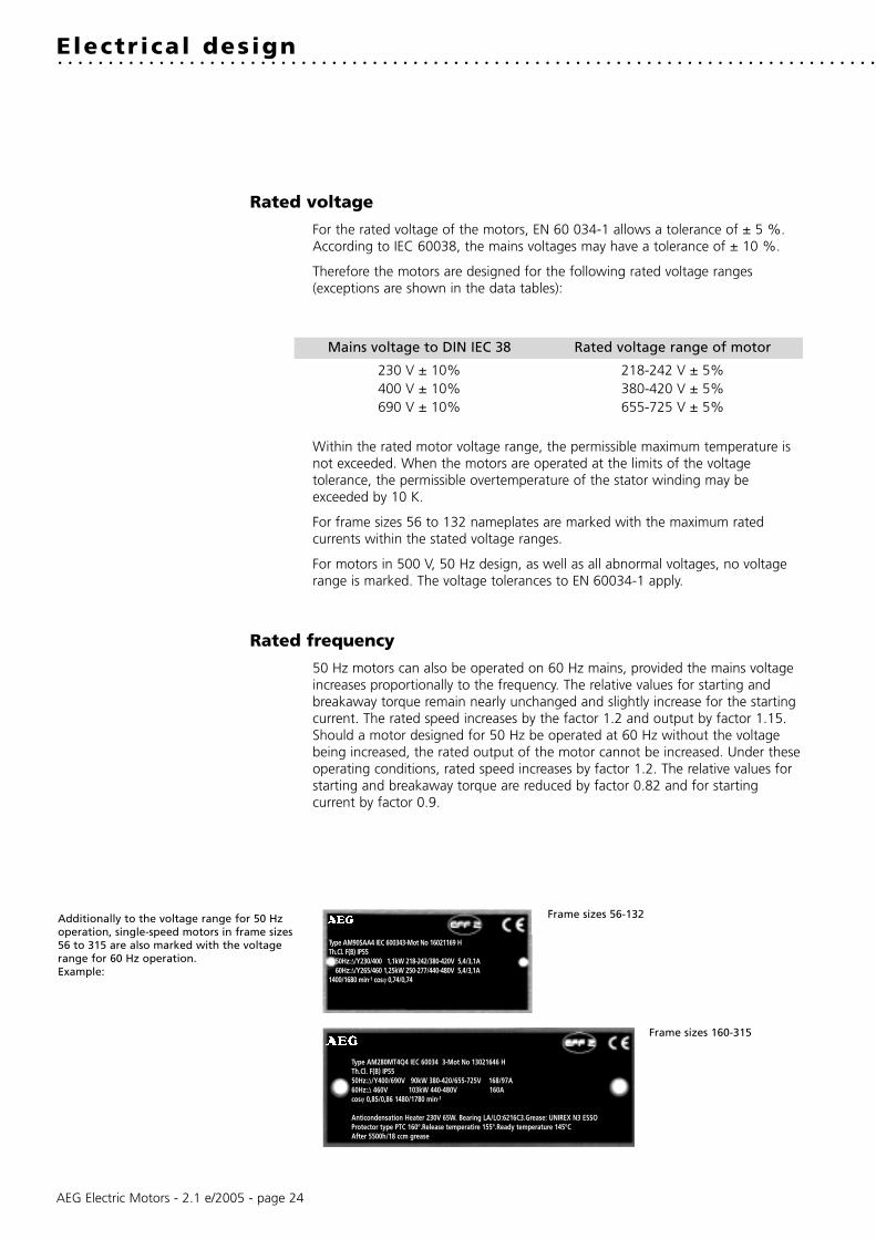
Rated voltage
For the rated voltage of the motors, EN 60 034-1 allows a tolerance of ± 5 %.According to IEC 60038, the mains voltages may have a tolerance of ± 10 %.
Therefore the motors are designed for the following rated voltage ranges(exceptions are shown in the data tables):
Mains voltage to DIN IEC 38 Rated voltage range of motor
230 V ± 10% 218-242 V ± 5%400 V ± 10% 380-420 V ± 5%690 V ± 10% 655-725 V ± 5%
Within the rated motor voltage range, the permissible maximum temperature isnot exceeded. When the motors are operated at the limits of the voltagetolerance, the permissible overtemperature of the stator winding may beexceeded by 10 K.
For frame sizes 56 to 132 nameplates are marked with the maximum ratedcurrents within the stated voltage ranges.
For motors in 500 V, 50 Hz design, as well as all abnormal voltages, no voltagerange is marked. The voltage tolerances to EN 60034-1 apply.
Rated frequency
50 Hz motors can also be operated on 60 Hz mains, provided the mains voltageincreases proportionally to the frequency. The relative values for starting andbreakaway torque remain nearly unchanged and slightly increase for the startingcurrent. The rated speed increases by the factor 1.2 and output by factor 1.15.Should a motor designed for 50 Hz be operated at 60 Hz without the voltagebeing increased, the rated output of the motor cannot be increased. Under theseoperating conditions, rated speed increases by factor 1.2. The relative values forstarting and breakaway torque are reduced by factor 0.82 and for startingcurrent by factor 0.9.
Frame sizes 56-132
Frame sizes 160-315
Additionally to the voltage range for 50 Hzoperation, single-speed motors in frame sizes56 to 315 are also marked with the voltagerange for 60 Hz operation.Example:
Type AM90SAA4 IEC 600343-Mot No 16021169 HTh.Cl. F(B) IP55
50Hz:∆/Y230/400 1,1kW 218-242/380-420V 5,4/3,1A60Hz:∆/Y265/460 1,25kW 250-277/440-480V 5,4/3,1A
1400/1680 min-1 cosϕ 0,74/0,74
Type AM280MT4Q4 IEC 60034 3-Mot No 13021646 HTh.Cl. F(B) IP55 50Hz:∆/Y400/690V 90kW 380-420/655-725V 168/97A60Hz:∆ 460V 103kW 440-480V 160Acosϕ 0,85/0,86 1480/1780 min-1
Anticondensation Heater 230V 65W. Bearing LA/LO:6216C3.Grease: UNIREX N3 ESSOProtector type PTC 160°.Release temperatire 155°.Ready temperature 145°CAfter 5500h/18 ccm grease

AEG Electric Motors - 2.1 e/2005 - page 25
Rated current
The rated currents listed in the data tables apply to an operating voltage of 400V. The conversion to other operating voltages, with output and frequencyremaining unchanged, is to be made as follows:
Nominal voltage (V) 230 380 400 440 500 660 690Conversion factor x lN 1.74 1.05 1.0 0.91 0.80 0.61 0.58
Rated torque
Rated voltage in kWRated torque in Nm = 9550 x
Rated speed in min-1
Output
The outputs stated in this catalogue are for constant load in continuous runningduty S1 according to EN 60034-1, based on an ambient temperature of 40° Cand installation at altitudes up to 1000 m above sea level.
For severe operating conditions, e.g. high switching rate, long run-up time orelectric braking, a thermal reserve is necessary, which could call for higherthermal class or the use of a motor with a higher rating. In these cases werecommend to enquire with detailed information on the operating conditions.
Overload
At operating temperature three-phase motors are capable of withstanding anoverload for 15 seconds at 1.5 times the rated torque at rated voltage. Thisoverload is according to EN 60034-1 and will not result in excessive heating.
Utilizing thermal class F, motors can be operated continuously with an overloadof 12 %. Nevertheless this is not valid for motors which to catalogue are utilizedto thermal class F.
Motor output 230 V ∆ 400 V ∆ 500 V Y 500 V ∆ 690 V ∆at 50 Hz 400 V Y 690 V Y
under 1.5 kW standard on request on request on request 1) -
1.5 to 4 kW standard standard on request on request -
5.5 to 90 kW standard standard on request standard standard
≥ 110 kW on request standard on request standard standard
1) Available from 0.25 kW
Connection

AEG Electric Motors - 2.1 e/2005 - page 26
Connection diagrams
Windings of standard three-phase motors can be connected either in star or deltaconnection.
Star connectionA star connection is obtained by connecting W2, U2, V2 terminals to eachotherand the U1, V1, W1 terminals to the mains. The phase current and voltage are:
Iph = In ; Uph = Un / 3
where In is the line current and Vn the line voltage referred to the starconnection.
Delta connectionA delta connection is obtained by connecting the end of a phase to thebeginning of the next phase.
The phase current Iph and the phase voltage Uph are:
Iph = In / 3 ; Uph = Un
where In and Un are referred to the delta connection.
Star-delta startingStar-delta starting allows a peak current reduction, ensuring however that thepeak torque obtained is bigger than the resistant torque. Actually, it should benoted that the torque of an induction squirrel-cage motor is directly proportionalto the square of the voltage. Motors whose rated voltage with delta connectioncorresponds to the mains voltage, can be started with the star-delta method.
All motors can be supplied with windings designed for star-delta starting (forexample: 400 V ∆ / 690 V Y).
Pole-changing motorsStandard pole-changing motors are designed for single voltage and direct-on-linestarting (special design for Y-∆-connection on request).
When the ratio between the two speeds is from 1 to 2, the standard motors haveone single winding (Dahlander connection). For the other speeds, the motorshave two separate windings.
V1W1
U1
L2 L3L1
U2
V1
W2
U1
V2
W1
V2U2
L3
W1V1
L1
W2
U1
L2
V1
U1
W1
AM/AMV - two separate windings /L3
2W
1W
L2L1
2V
1V
2U
1U
2V2W
2W
1W
2V
1V
L3
2U
1U
L1
1U
1V1W
Low speedL2
2U
High speed
AM/AMV - two separate windings Y/Y
High speed
2W2V
L3
1W1V
L1
2U
1U
L2
2W2V
L3
1W1V
L1
2U
1U
L2
1V
1U
1W
Low speed
2W
2U
2V
AM - Dahlander connection /YY
Low speed High speedL3L1 L2
2W
1W
2V
1V
2U
1U
2W2V
L3
1W1V
L1
2U
1U
L2
2U
2V2W2U
2W2V
1U
1V1W
1V
1U
1W
AMV - Dahlander connection Y/YY
High speed
2W 2V
1W1U
1V
2U
2U2V
2W
Low speed
1W
2W
1V
2V
L3L1
1U
2U
L2
2W2V
L3
1W1V
L1
2U
1U
L2
1V
1U
1W

AEG Electric Motors - 2.1 e/2005 - page 27
Insulation and temperature rise
Class F insulation to EN 60034-1 is used throughout.
In standard design motors are intended for operation at 40° C ambienttemperature with class B temperature rise only, with an overtemperaturelimit of 80 K. This also applies for the rated voltage range to IEC 60038.Exceptions are shown on the data tables.
Temperature rise (∆T*) and maximum temperatures at the hottest points of thewinding (Tmax) according to the temperature classes of EN 60034-1.
∆T* Tmax
Class B 80 K 125° CClass F 105 K 155° CClass H 125 K 180° C
*Measurement by resistance method
Output reduction at ambient temperatures over 40° C
Ambient temperature 45° C 50° C 55° C 60° CReduction of nominal output to approx. 95 % 90 % 85 % 80 %
When a winding is utilized to temperature class F (105K), no output reduction isrequired up to an ambient temperature of 60° C. This does not apply to motorswhich in their standard design are already utilized to thermal class F.

AEG Electric Motors - 2.1 e/2005 - page 28
Installation at altitudes of more than 1000 m above sea level (see also EN 60034-1)
Altitude of installation 2000 m 3000 m 4000 m
At 40°C ambient temperature and thermal class BRated output reduced to approx. 92 % 84 % 76 %
At 40°C ambient temperature and thermal class FRated output reduced to approx. 89 % 79 % 68 %
Full nominal output to data tables with thermal class B and ambient temperature of 32° C 24° C 16° C
Full nominal output to data tables with thermal class F and ambient temperature of 30° C 19° C 9° C
Starting rate
The permissible number of starts per hour can be taken as given in the tablebelow, provided the following conditions are met:
Additional moment of inertia ≤ moment of inertia of the rotor: load torque risingwith the square of the speed up to nominal torque; starts at even intervals.
Shaft height Permissible No. of starts per hour for 2p
= 2 = 4 ≥ 6
56 - 71 100 250 350
80 - 100 60 140 160
112 - 132 30 60 80
160 - 180 15 30 50
200 - 225 8 15 30
250 - 315 4 8 12
For permissible number of starts for larger and pole-changing motors pleaseconsult us, indicating the complete operating conditions.
AEG Electric Motors - 2.1 e/2005 - page 29
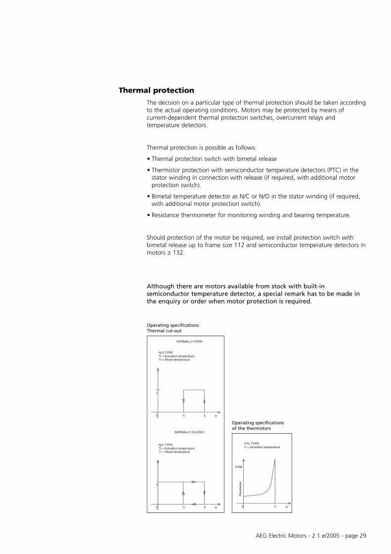
Thermal protection
The decision on a particular type of thermal protection should be taken accordingto the actual operating conditions. Motors may be protected by means ofcurrent-dependent thermal protection switches, overcurrent relays andtemperature detectors.
Thermal protection is possible as follows:
• Thermal protection switch with bimetal release
• Thermistor protection with semiconductor temperature detectors (PTC) in thestator winding in connection with release (if required, with additional motorprotection switch).
• Bimetal temperature detector as N/C or N/O in the stator winding (if required,with additional motor protection switch).
• Resistance thermometer for monitoring winding and bearing temperature.
Should protection of the motor be required, we install protection switch withbimetal release up to frame size 112 and semiconductor temperature detectors inmotors ≥ 132.
Although there are motors available from stock with built-insemiconductor temperature detector, a special remark has to be made inthe enquiry or order when motor protection is required.
NORMALLY OPEN
N/O TYPE
Tr = Reset temperatureTi = Activation temperature
1
Tr0 Ti K
NORMALLY CLOSED
N/C TYPE
Tr = Reset temperatureTi = Activation temperature
KTi
1
Tr0
PTC TYPE
Res
ista
nce
Ti = Activation temperature
0
OHM
KTi
Operating specificationsThermal cut-out
Operating specificationsof the thermistors

AEG Electric Motors - 2.1 e/2005 - page 30
Protection method Protection
Motor protection switch with thermal and against:electromagnetic overcurrent release • Overload in continuous service
• Locked rotor
Contactor with overcurrent relay in service against:Thermistor protection and fuse • Overload in continous service
• Long starting and braking periods• High switching ratein case of fault against:• Obstruction of cooling• Increased ambient temperature• Single-phase operation• Frequency fluctuations• Switching against locked rotor
Semiconductor temperature detector in service against:with release • Overload in continous service
• Long starting and braking periods• High switching ratein case of fault against:• Obstruction of cooling• Increased ambient temperature• Single-phase operation• Frequency fluctuations• Switching against locked rotor
Examples of connection

AEG Electric Motors - 2.1 e/2005 - page 31
The motors frame sizes 90 upwards in standard design are suitable for operationon static frequency converters, taking into account the following remarks:
• Maximum converter output voltage 500V at peak voltages Û ≤ 1460V and du/dt ≤ 13 kV/us. For higher converter output voltages or stresses, a special insulation is required.
• With square characteristic of the load torque, motors can be driven with their rated torque.
• For constant torque, the rated torque of motors with internal cooling must be reduced due to reduced cooling air inlet. Depending on the control range, the use of an external fan would be advisable.
• The motors frame sizes 90 – 112 are suitable for a maximum output frequency of the converter of 60 Hz (e.g. applications with square torque, control range 1 : 10,such as pumps and fans). For higher frequencies, a special range with type designation AMI is available on request. From frame size 132 upwards, motors designed ∆/Y 230/400 V, 50 Hz can be operated in delta with a maximum frequency of 87 Hz (observe mechanical limit speed).
• Insulated or hybride bearings may be necessary on critical applications. Wegenerally recommend the use of insulated bearings for motors frame size 225upwards.
The motors frame size 56 – 80 can be operated on single-phase converters up tomaximum 60 Hz. (Special range with type designation AMI for operation on three-phase converters with output voltage ≥ 400 V and output frequency > 60 Hz).
The electrical values and dimensions of the range AMI in frame size 56 to 112are identical to AM motors (see data tables pages 36-41).
Noise
Depending on the operating point and converter type, converter-fed motorsproduce between approx. 4 - 10 dB(A) higher noise values than when suppliedfrom the mains. For motors driven with a frequency over 50 Hz, more fan noise isproduced. We recommend the use of an external fan.
Three-phase cage motors driven byfrequency converters. . . . . . . . . . . . . . . . . . . . . . . . . . . . . . . . . . . . . . . . . . . . . . . . . . . . . . . . . . . . . . . . . . . . . . . . . . . . . . .
3
External cooling1
2
3
2
1
Internal cooling motors 2p = 2
Internal cooling motors 2p = 4-8
no field weakening
with field weakening
f [Hz]
MU/MN
Thermal maximum-torque curve forapproximate determination of therequired torque reduction withconstant load torque curve

Degree of protection
Depending on the accessories used.
Mechanical limit speeds
For motors of standard design, the following maximum operating speeds arepermitted:
Frame size 2p = 2 2 p = 4 - 8
min -1 min -1
56-112 1) 3600 1800
132-180 6000 6000
200 5000 5000
225 4500 4500
250 4300 4300
280, 315S YE 4300 3800
315S / M ZE 3600 3600
315 L 3600 3000
1) Higher speeds with special range AMI
Vibration amplitude
When operating at high speeds (according to frequency > 60 Hz) a reducedvibration amplitude “R” to DIN ISO 2373/DIN VDE 0530, part 14 may berequired, measured at a mains frequency of 50 Hz or 60 Hz and sinusoidal mainsvoltage.
Accessories
Motors are available with the following accessory:· Encoder with internal or external cooling
Encoder (standard design)
Supply voltage UB 5 V
Pulses per revolution 500-2048
Outputs 2 signals with rectangular pulses A, B2 signals with inverted rectangular pulses A, B zero pulse and inverted zero pulse
Pulse displacement between outputs 90º
Output amplitude UHigh 2.5 V
ULow 0.5 V
Maximum frequency 100 kHz
Maximum speed 3,000 (6,000) min -1
Temperature range -20ºC to + 85ºC
Degree of protection IP 54
AEG Electric Motors - 2.1 e/2005 - page 32

AEG Electric Motors - 2.1 e/2005 - page 33
Order data. . . . . . . . . . . . . . . . . . . . . . . . . . . . . . . . . . . . . . . . . . . . . . . . . . . . . . . . . . . . . . . . . . . . . . . . . . . . . . .
Motors for normal continuous duty (S1) and normaloperating conditions
Quotation (if submitted) No./DateQuantity UnitsDesignation Type
Output (for pole-changing motors, outputs referred to speeds) kW
Speed (for pole-changing motors, outputs referred to outputs) min-1
Direction of rotation (viewed on shaft extension)
Mounting arrangement (to IEC 60034-7)
Degree of protection, motor/terminal box (to IEC 60034-5)
Mains voltage V
Mains frequency Hz
Method of starting (direct-on-line or Y-∆)
Location of terminal box
Machine to be driven
Dimensions of cables, if these differ from those allocated by VDE0100, referred to an ambient temperature of 40° C, or whenaluminium conductors are used. It should be stated when parallelconnected conductors are used.
Additional information for special designs
Second or non-standard shaft extensionRadial sealing ringPaint coatingCorrosive protectionVibration levelAnti-condensation heatingTemperature detectorsNoise requirementsMechanical or electrical brakeSpecial stipulations
AEG Electric Motors - 2.1 e/2005 - page 34
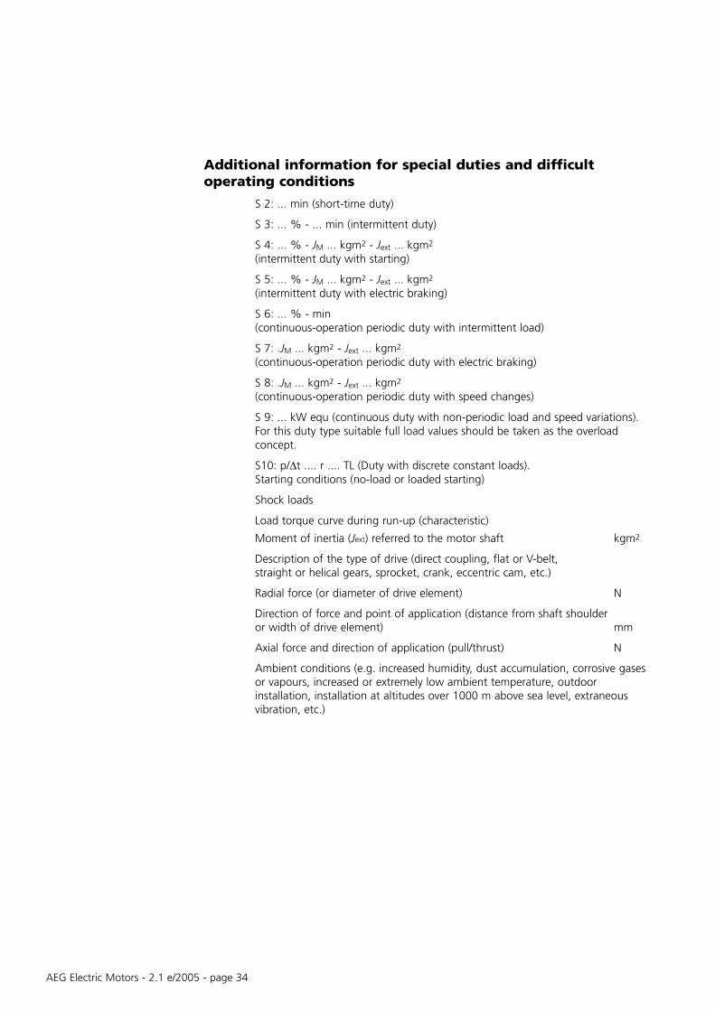
Additional information for special duties and difficultoperating conditions
S 2: ... min (short-time duty)
S 3: ... % - ... min (intermittent duty)
S 4: ... % - JM ... kgm2 - Jext ... kgm2
(intermittent duty with starting)
S 5: ... % - JM ... kgm2 - Jext ... kgm2
(intermittent duty with electric braking)
S 6: ... % - min (continuous-operation periodic duty with intermittent load)
S 7: .JM ... kgm2 - Jext ... kgm2
(continuous-operation periodic duty with electric braking)
S 8: .JM ... kgm2 - Jext ... kgm2
(continuous-operation periodic duty with speed changes)
S 9: ... kW equ (continuous duty with non-periodic load and speed variations). For this duty type suitable full load values should be taken as the overloadconcept.
S10: p/∆t .... r .... TL (Duty with discrete constant loads).Starting conditions (no-load or loaded starting)
Shock loads
Load torque curve during run-up (characteristic)
Moment of inertia (Jext) referred to the motor shaft kgm2
Description of the type of drive (direct coupling, flat or V-belt, straight or helical gears, sprocket, crank, eccentric cam, etc.)
Radial force (or diameter of drive element) N
Direction of force and point of application (distance from shaft shoulderor width of drive element) mm
Axial force and direction of application (pull/thrust) N
Ambient conditions (e.g. increased humidity, dust accumulation, corrosive gasesor vapours, increased or extremely low ambient temperature, outdoorinstallation, installation at altitudes over 1000 m above sea level, extraneousvibration, etc.)

AEG Electric Motors - 2.1 e/2005 - page 35
Apart from other information, it is necessary to specify the exact type designation in all enquiries, when ordering spareparts or replacement motors or when asking for documentary information.
The type designation of our motors comprises 9 points of reference, each of which may consist of several letters and/ornumerals. The meaning of each symbol can be seen from the following table. For motors not included in our standardrange, special symbols may be used which are not listed here.
Ref. Meaning Description of symbols used for our motorspoint
1 Type of motor A Asynchronous motor
2 Cooling M Surface cooled with external fan, cooling finsG Surface cooled without external fan, cooling finsMFV Surface cooled with forced ventilation, cooling fins
3 Type of motor blank Three-phase motorV Three-phase pole-changing motor for driving fansH Three-phase motor, efficiency to EPACT regulationsHE Three-phase motor, efficiency eff 1 to CEMEP Voluntary AgreementI Special design for three-phase motor driven with frequency converter
4 Shaft centre height 56, 63, 71, 80, 90, 100, 112, 132,160, 180, 200, 225, 250, 280, 315
5 Frame length ZS Mechanical dimension (short)M Mechanical dimension (medium)L Mechanical dimension (long)
6 Mechanical A Frame Stage of X,P,J Framedesign and B size development Y,R,L sizeoutput value C 56-112 Z,V,T 132-315
D
7 Frame material A Aluminium frameand/or stage of G Cast iron framedevelopment E Stage of development
8 Number of poles 2 4/24 8/46 4/68 6/8
9 Special features R3 High resistance rotor
Type designation. . . . . . . . . . . . . . . . . . . . . . . . . . . . . . . . . . . . . . . . . . . . . . . . . . . . . . . . . . . . . . . . . . . . . . . . . . . . . . .
Meaning of the symbols
Examples

AEG Electric Motors - 2.1 e/2005 - page 36
Three-phase squirrel cage motors For mains voltagedesigned for range of rated voltage to IEC 60038380-420 V ± 5% - 50 Hz 400 V ± 10% - 50 Hz
Type Rated Rated Efficiency Power Rated Direct-on-line starting Moment Weightoutput speed factor current Starting Breakaway Pull-up Pull-out of
at current torque torque torque inertiaratio ratio ratio ratio
η cos ϕ IN IA/IN MA/MN MS/MN MK/MN kW HP min-1 50% 75% 100% 400V 380-420V 10-3 kgm2 kg
3000 min-1 (2 poles) Aluminium frame
AM 56Z AA 2 0.09 0.12 2810 49 53 58.3 0.62 0.38 0.4 3.9 3.8 3.8 3.9 0.09 3.4AM 56Z BA 2 0.12 0.16 2800 51 56 61.6 0.70 0.4 0.42 3.9 3.8 3.8 3.9 0.1 3.5
AM 63Z AA 2 0.18 0.25 2790 54 58 63 0.77 0.6 0.66 4.2 3 3.1 3.2 0.13 4.1AM 63Z BA 2 0.25 0.33 2790 56.4 61.2 65.3 0.77 0.71 0.75 4.5 3.2 3.2 3.3 0.19 4.6AM 63Z CA 2* 0.37 1) 0.50 1) 2800 54 58 63 0.75 1.13 1.25 4.6 3.4 3.3 3.4 0.20 4.7
AM 71Z AA 2 0.37 0.50 2820 54 60.5 65.3 0.70 1.1 1.2 4.7 3.6 3.4 3.6 0.36 5.7AM 71Z BA 2 0.55 0.75 2830 57 64 70.8 0.70 1.6 1.7 4.8 3.2 3.1 3.3 0.46 6.3AM 71Z CA 2* 0.75 1) 1.0 1) 2800 58 64.3 71 0.75 1.9 2.0 5.2 3.1 3.2 3.1 0.58 6.9
AM 80Z AA 2 0.75 2840 67.7 73.0 74.5 0.78 1.9 2.0 5.0 2.8 2.8 2.9 0.75 8.4AM 80Z BA 2 1.1 1.5 2810 74.3 77.3 77.6 0.82 2.5 2.6 4.6 2.4 2.8 2.9 0.89 9.5AM 80Z CA 2* 1.5 1) 2.0 1) 2825 76.5 79.4 79.1 0.83 3.3 3.4 5.0 2.9 3.0 3.3 1.05 11.1
AM 90S AA 2 1.5 2.0 2830 75.4 78.4 78.6 0.82 3.4 3.5 5.0 3.1 2.9 3.0 1.37 12.7AM 90S BA 2* 1.8 2.5 2805 75.18 78.3 78.5 0.80 4.2 4.3 4.5 2.6 2.4 2.5 1.37 12.7AM 90L CA 2 2.2 3.0 2860 78.6 81.4 81.8 0.81 4.9 4.9 7.1 4.1 3.6 4.0 1.8 16.0AM 90L DA 2* 3 1) 4.0 1) 2860 78.8 81.9 82.3 0.80 6.5 6.8 7.2 3.9 3.4 3.8 2.09 18.7
AM 100L AA 2 3 4.0 2860 81.7 82.2 82.6 0.85 6.4 6.7 6.0 3.1 3.1 3.3 2.80 19.3AM 100L BA 2* 4 1) 5.5 1) 2835 82.4 83.8 83.0 0.88 8.0 8.1 6.2 2.9 2.5 2.9 3.35 19.7AM 100L CA 2* 5.5 1) 7.5 1) 2865 83.5 85.3 85.0 0.85 10.8 11.0 7.2 3.5 3.4 4.1 4.5 25.9
AM 112M AA 2 4 5.5 2900 80.9 84.2 85.0 0.84 8.5 8.7 8.1 3.8 3.6 4.0 6.48 27.4AM 112M BA 2* 5.5 1) 7.5 1) 2930 81.0 84.7 86.2 0.81 11.5 12.3 9.0 4.2 2.6 3.6 8.58 33.6
AM 132S YA 2 5.5 7.5 2885 84.7 86.2 85.7 0.86 10.8 11.0 6.6 2.5 2.1 2.9 10.0 40AM 132S ZA 2 7.5 10.0 2890 86.5 87.6 87.0 0.89 14.1 14.5 7.2 2.6 2.2 3.0 14.0 45AM 132M ZA 2* 9.2 1) 12.5 1) 2870 84.5 86.6 86.7 0.83 18.7 19.8 7.0 2.8 2.4 3.2 14.0 48AM 132M RA 2* 11 15.0 2900 88.2 89.2 88.7 0.87 20.6 21 7.8 2.9 2.5 3.3 20.5 53AM 132M TA 2* 15 1) 20.0 1) 2890 88.0 89.0 88.5 0.88 28.0 28.5 7.8 3.1 2.6 3.4 25.0 59
AM 160M VA 2 11 15 2925 86.6 88.5 88.7 0.84 21.5 22 6.7 2.3 2.2 3.0 28 81AM 160M XA 2 15 20 2920 88.0 89.6 89.7 0.85 28.5 29.5 7.2 2.4 2.2 3.1 36 93AM 160L XA 2 18.5 25 2925 88.8 90.3 90.4 0.86 34.5 35 7.6 2.7 2.5 3.3 42 101AM 160L RA 2* 22 1) 30 1) 2920 89.0 90.8 90.8 0.87 41 42 7.9 2.7 2.5 3.3 52 114
AM 180M XA 2 22 30 2925 89.1 90.7 90.8 0.86 41 42 7.4 2.5 2.3 3.2 65 130AM 180M RA 2* 30 1) 40 1) 2925 89.3 91.4 91.5 0.86 56 57.5 7.9 2.7 2.5 3.4 88 150
1) Temperature rise to class F
* Higher output (progressive motor)
Temperature rise to class B

AEG Electric Motors - 2.1 e/2005 - page 37
Type Rated Rated Efficiency Power Rated Direct-on-line starting Moment Weightoutput speed factor current Starting Breakaway Pull-up Pull-out of
at current torque torque torque inertiaratio ratio ratio ratio
η cos ϕ IN IA/IN MA/MN MS/MN MK/MN kW HP min-1 50% 75% 100% 400V 380-420V 10-3 kgm2 kg
3000 min-1 (2 poles) Cast iron frame
AM 132S YG 2 5.5 7.5 2885 84.7 86.2 85.7 0.86 10.8 11.0 6.6 2.5 2.1 2.9 10.0 55AM 132S ZG 2 7.5 10.0 2890 86.5 87.6 87.0 0.89 14.1 14.5 7.2 2.6 2.2 3.0 14.0 60AM 132M ZG 2* 9.2 1) 12.5 1) 2870 84.5 86.6 86.7 0.83 18.7 19.8 7.0 2.8 2.4 3.2 14.0 63AM 132M RG 2* 11 15.0 2900 88.2 89.2 88.7 0.87 20.6 21 7.8 2.9 2.5 3.3 20.5 68AM 132M TG 2* 15 1) 20.0 1) 2890 88.0 89.0 88.5 0.88 28.0 28.5 7.8 3.1 2.6 3.4 25.0 74
AM 160M VG 2 11 15 2925 86.6 88.5 88.7 0.84 21.5 22 6.7 2.3 2.2 3.0 28 101AM 160M XG 2 15 20 2920 88.0 89.6 89.7 0.85 28.5 29.5 7.2 2.4 2.2 3.1 36 113AM 160L XG 2 18.5 25 2925 88.8 90.3 90.4 0.86 34.5 35 7.6 2.7 2.5 3.3 42 121AM 160L RG 2* 22 1) 30 1) 2920 89.0 90.8 90.8 0.87 41 42 7.9 2.7 2.5 3.3 52 134
AM 180M XG 2 22 30 2925 89.1 90.7 90.8 0.86 41 42 7.4 2.5 2.3 3.2 65 155AM 180M RG 2* 30 1) 40 1) 2925 89.3 91.4 91.5 0.86 56 57.5 7.9 2.7 2.5 3.4 88 175
AM 200L LG 2 30 40 2945 89.2 91.1 91.6 0.85 56 57 7.8 2.2 2.0 3.0 120 212AM 200L NG 2 37 50 2950 90.0 91.8 92.2 0.86 67.5 69 7.7 2.2 2.0 3.0 145 230
AM 225M N 2 45 60 2945 90.9 92.4 92.6 0.89 80 83 7.8 2.4 1.9 2.8 270 310
AM 250M N 2 55 75 2950 90.9 92.7 93.1 0.89 96 101 7.5 2.3 1.8 3.0 424 410
AM 280S T 2 75 100 2975 90.9 92.9 93.7 0.87 134 136 7.2 1.9 1.5 3.2 770 540AM 280M T 2 90 125 2975 93.6 94.8 94.1 0.89 156 161 7.3 1.9 1.5 3.2 957 615
AM 315S YE 2 110 150 2975 92.8 94.4 95.0 0.87 193 198 7.8 1.9 1.5 3.2 1000 650AM 315M ZE 2 132 180 2980 94.1 95.2 95.5 0.88 227 235 6.8 2.4 1.3 2.6 1200 810AM 315L YE 2 160 220 2980 94.7 95.7 95.9 0.90 267 280 7.2 2.5 1.3 2.6 1400 900AM 315L ZE 2 200 1) 270 1) 2980 95.2 96.1 96.3 0.91 329 347 7.8 2.7 1.3 2.7 1600 1000
1) Temperature rise to class F
* Higher output (progressive motor)
Temperature rise to class B

AEG Electric Motors - 2.1 e/2005 - page 38
Three-phase squirrel cage motors For mains voltagedesigned for range of rated voltage to IEC 60038380-420 V ± 5% - 50 Hz 400 V ± 10% - 50 Hz
Type Rated Rated Efficiency Power Rated Direct-on-line starting Moment Weightoutput speed factor current Starting Breakaway Pull-up Pull-out of
at current torque torque torque inertiaratio ratio ratio ratio
η cos ϕ IN IA/IN MA/MN MS/MN MK/MN kW HP min-1 50% 75% 100% 400V 380-420V 10-3 kgm2 kg
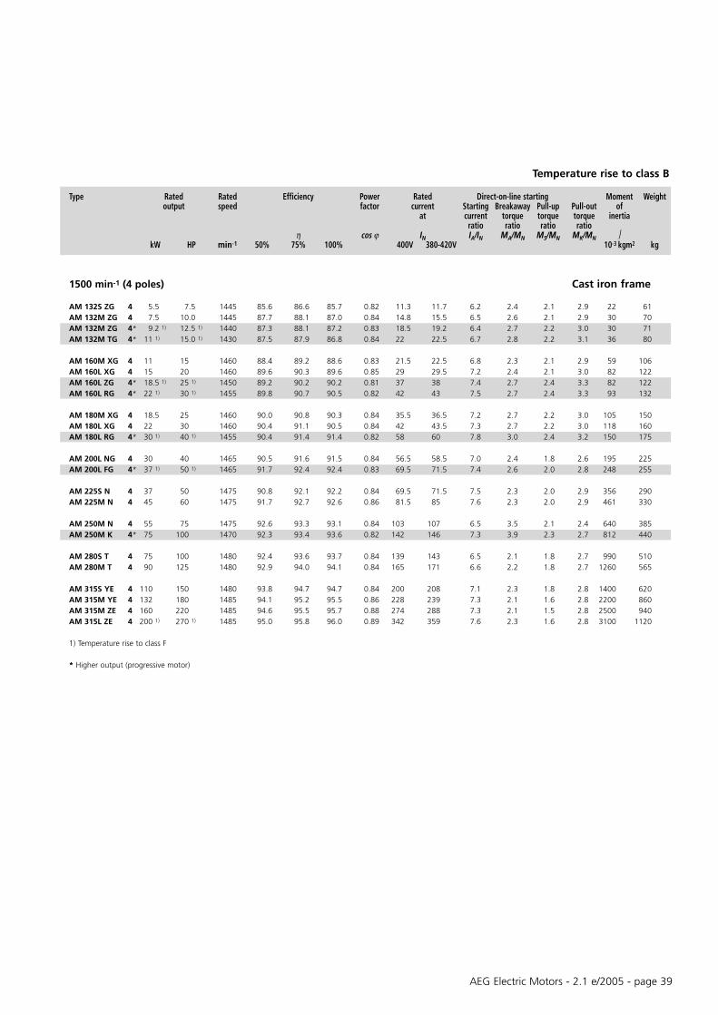
1500 min-1 (4 poles) Aluminium frame
AM 56Z AA 4 0.06 0.08 1300 42 44 48 0.55 0.35 0.4 2.6 2.1 2.0 2.1 0.14 3.2AM 56Z BA 4* 0.09 0.12 1330 43 47 51 0.60 0.4 0.45 2.5 2.2 2.1 2.2 0.14 3.3
AM 63Z AA 4 0.12 0.16 1350 46 50 54 0.69 0.45 0.5 2.4 2.0 1.9 2.0 0.25 4.1AM 63Z BA 4 0.18 0.25 1330 47 50 56 0.70 0.6 0.65 2.3 1.9 1.8 1.9 0.27 4.6AM 63Z CA 4* 0.25 0.33 1360 49 52.5 58 0.60 1.0 1.2 2.7 2.2 2.0 2.1 0.30 4.9
AM 71Z AA 4 0.25 0.33 1340 55 59 64 0.71 0.7 0.8 3.2 1.9 1.8 2.0 0.63 5.2AM 71Z BA 4 0.37 0.50 1370 60 63 67 0.67 1.18 1.25 3.3 2.2 2.1 2.2 0.76 5.4AM 71Z CA 4* 0.55 1) 0.75 1) 1380 61 64 68 0.67 1.73 1.8 3.6 2.4 2.3 2.4 0.98 6.3
AM 80Z AA 4 0.55 0.75 1400 67.0 69.0 70.0 0.72 1.6 1.7 3.6 2.6 2.5 2.6 1.58 8.2AM 80Z BA 4 0.75 1.0 1410 62.5 69.0 70.6 0.71 2.2 2.3 4.4 2.8 2.3 2.8 2.00 9.3AM 80Z CA 4* 1.1 1) 1.5 1) 1385 74.1 76.4 75.9 0.77 2.8 2.9 4.4 2.5 2.5 2.6 2.41 10.6
AM 90S AA 4 1.1 1.5 1400 69.6 75.4 76.5 0.78 2.7 2.9 5.2 2.5 2.4 2.8 2.5 12.5AM 90L BA 4 1.5 2.0 1400 75.6 78.7 78.6 0.77 3.6 3.7 5.7 2.8 2.6 3.0 3.13 14.5AM 90L CA 4* 1.8 1) 2.5 1) 1380 75.1 77.8 77.3 0.80 4.2 4.3 5.5 2.7 2.5 2.9 3.13 14.5AM 90L DA 4* 2.2 1) 3.0 1) 1400 76.3 79.3 79.3 0.75 5.3 5.5 4.8 2.9 2.8 3.2 4.05 17
AM 100L AA 4 2.2 3.0 1435 77.5 80.2 81.0 0.74 5.4 5.6 5.3 2.5 2.4 2.7 4.6 19.5AM 100L BA 4 3 4.0 1425 81.7 83.4 82.8 0.76 6.8 6.9 4.6 2.4 2.3 2.5 5.58 22.5AM 100L CA 4* 4 1) 5.5 1) 1400 82.1 83.0 81.6 0.78 9.2 9.3 6.0 2.6 2.4 2.9 6.05 25
AM 112M AA 4 4 5.5 1430 84.5 85.3 84.2 0.81 8.5 8.8 6.3 2.2 2.0 2.8 12.2 29.5AM 112M BA 4* 5.5 1) 7.5 1) 1430 85.9 86.2 85.2 0.83 11.4 11.7 6.5 2.2 2.0 2.9 15.2 34
AM 132S ZA 4 5.5 7.5 1445 85.6 86.6 85.7 0.82 11.3 11.7 6.2 2.4 2.1 2.9 22 46AM 132M ZA 4 7.5 10.0 1445 87.7 88.1 87.0 0.84 14.8 15.5 6.5 2.6 2.1 2.9 30 55AM 132M ZA 4* 9.2 1) 12.5 1) 1440 87.3 88.1 87.2 0.83 18.5 19.2 6.4 2.7 2.2 3.0 30 56AM 132M TA 4* 11 1) 15.0 1) 1430 87.5 87.9 86.8 0.84 22 22.5 6.7 2.8 2.2 3.1 36 65
AM 160M XA 4 11 15 1460 88.4 89.2 88.6 0.83 21.5 22.5 6.8 2.3 2.1 2.9 59 86AM 160L XA 4 15 20 1460 89.6 90.3 89.6 0.85 29 29.5 7.2 2.4 2.1 3.0 82 102AM 160L ZA 4* 18.5 1) 25 1) 1450 89.2 90.2 90.2 0.81 37 38 7.4 2.7 2.4 3.3 82 102AM 160L RA 4* 22 1) 30 1) 1455 89.8 90.7 90.5 0.82 42 43 7.5 2.7 2.4 3.3 93 112
AM 180M XA 4 18.5 25 1460 90.0 90.8 90.3 0.84 35.5 36.5 7.2 2.7 2.2 3.0 105 125AM 180L XA 4 22 30 1460 90.4 91.1 90.5 0.84 42 43.5 7.3 2.7 2.2 3.0 118 135AM 180L RA 4* 30 1) 40 1) 1455 90.4 91.4 91.4 0.82 58 60 7.8 3.0 2.4 3.2 150 150
1) Temperature rise to class F
* Higher output (progressive motor)
Temperature rise to class B
AEG Electric Motors - 2.1 e/2005 - page 39
Type Rated Rated Efficiency Power Rated Direct-on-line starting Moment Weightoutput speed factor current Starting Breakaway Pull-up Pull-out of
at current torque torque torque inertiaratio ratio ratio ratio
η cos ϕ IN IA/IN MA/MN MS/MN MK/MN kW HP min-1 50% 75% 100% 400V 380-420V 10-3 kgm2 kg
1500 min-1 (4 poles) Cast iron frame
AM 132S ZG 4 5.5 7.5 1445 85.6 86.6 85.7 0.82 11.3 11.7 6.2 2.4 2.1 2.9 22 61AM 132M ZG 4 7.5 10.0 1445 87.7 88.1 87.0 0.84 14.8 15.5 6.5 2.6 2.1 2.9 30 70AM 132M ZG 4* 9.2 1) 12.5 1) 1440 87.3 88.1 87.2 0.83 18.5 19.2 6.4 2.7 2.2 3.0 30 71AM 132M TG 4* 11 1) 15.0 1) 1430 87.5 87.9 86.8 0.84 22 22.5 6.7 2.8 2.2 3.1 36 80
AM 160M XG 4 11 15 1460 88.4 89.2 88.6 0.83 21.5 22.5 6.8 2.3 2.1 2.9 59 106AM 160L XG 4 15 20 1460 89.6 90.3 89.6 0.85 29 29.5 7.2 2.4 2.1 3.0 82 122AM 160L ZG 4* 18.5 1) 25 1) 1450 89.2 90.2 90.2 0.81 37 38 7.4 2.7 2.4 3.3 82 122AM 160L RG 4* 22 1) 30 1) 1455 89.8 90.7 90.5 0.82 42 43 7.5 2.7 2.4 3.3 93 132
AM 180M XG 4 18.5 25 1460 90.0 90.8 90.3 0.84 35.5 36.5 7.2 2.7 2.2 3.0 105 150AM 180L XG 4 22 30 1460 90.4 91.1 90.5 0.84 42 43.5 7.3 2.7 2.2 3.0 118 160AM 180L RG 4* 30 1) 40 1) 1455 90.4 91.4 91.4 0.82 58 60 7.8 3.0 2.4 3.2 150 175
AM 200L NG 4 30 40 1465 90.5 91.6 91.5 0.84 56.5 58.5 7.0 2.4 1.8 2.6 195 225AM 200L FG 4* 37 1) 50 1) 1465 91.7 92.4 92.4 0.83 69.5 71.5 7.4 2.6 2.0 2.8 248 255
AM 225S N 4 37 50 1475 90.8 92.1 92.2 0.84 69.5 71.5 7.5 2.3 2.0 2.9 356 290AM 225M N 4 45 60 1475 91.7 92.7 92.6 0.86 81.5 85 7.6 2.3 2.0 2.9 461 330
AM 250M N 4 55 75 1475 92.6 93.3 93.1 0.84 103 107 6.5 3.5 2.1 2.4 640 385AM 250M K 4* 75 100 1470 92.3 93.4 93.6 0.82 142 146 7.3 3.9 2.3 2.7 812 440
AM 280S T 4 75 100 1480 92.4 93.6 93.7 0.84 139 143 6.5 2.1 1.8 2.7 990 510AM 280M T 4 90 125 1480 92.9 94.0 94.1 0.84 165 171 6.6 2.2 1.8 2.7 1260 565
AM 315S YE 4 110 150 1480 93.8 94.7 94.7 0.84 200 208 7.1 2.3 1.8 2.8 1400 620AM 315M YE 4 132 180 1485 94.1 95.2 95.5 0.86 228 239 7.3 2.1 1.6 2.8 2200 860AM 315M ZE 4 160 220 1485 94.6 95.5 95.7 0.88 274 288 7.3 2.1 1.5 2.8 2500 940AM 315L ZE 4 200 1) 270 1) 1485 95.0 95.8 96.0 0.89 342 359 7.6 2.3 1.6 2.8 3100 1120
1) Temperature rise to class F
* Higher output (progressive motor)
Temperature rise to class B

AEG Electric Motors - 2.1 e/2005 - page 40
Type Rated Rated Efficiency Power Rated Direct-on-line starting Moment Weightoutput speed factor current Starting Breakaway Pull-up Pull-out of
at current torque torque torque inertiaratio ratio ratio ratio
η cos ϕ IN IA/IN MA/MN MS/MN MK/MN kW HP min-1 50% 75% 100% 400V 380-420V 10-3 kgm2 kg
1000 min-1 (6 poles) Aluminium frame
AM 71Z AA 6 0.18 0.25 850 44.0 47.0 51.0 0.73 0.7 0.75 2.2 1.6 1.5 1.6 0.6 5.7AM 71Z BA 6 0.25 1) 0.33 1) 870 46.0 50.0 54.0 0.68 1.0 1.1 2.5 1.7 1.6 1.7 0.9 6.3
AM 80Z AA 6 0.37 0.5 910 47.0 58.0 60.0 0.72 1.2 1.25 2.7 1.6 1.6 2.1 1.97 8AM 80Z BA 6 0.55 0.75 910 60.0 64.0 68.0 0.67 1.8 1.8 2.9 2.2 2.1 2.1 2.47 9.4
AM 90S AA 6 0.75 1 910 71.0 73.0 72.0 0.63 2.4 2.5 2.9 1.7 1.5 1.7 3.18 11.6AM 90L BA 6 1.1 1.5 908 71.0 73.0 72.0 0.63 3.5 3.6 3.0 1.7 1.5 1.7 4.78 15
AM 100L AA 6 1.5 2 930 70.0 75.0 72.0 0.71 4.2 4.4 3.7 1.8 1.8 2.3 6.73 17.5AM 100L BA 6* 1.8 2.5 940 71.0 75.0 76.0 0.67 5.1 5.3 4.2 2.4 2.4 2.8 9.43 22
AM 112M AA 6 2.2 3 940 81.0 83.0 82.0 0.72 5.3 5.4 4.4 2.4 2.4 2.6 14.18 26AM 112M BA 6* 2.6 3.5 930 82.2 83.7 82.4 0.73 6.3 6.5 4.9 3.0 2.9 3.1 16.73 29.7AM 112M CA 6* 3 4 940 83.0 84.0 84.0 0.75 7.0 7.2 5.3 2.9 2.9 2.9 18.7 39
AM 132S ZA 6 3 4 955 81.6 83.7 83.4 0.75 7.0 7.1 5.8 2.1 1.8 2.7 27 43AM 132M YA 6 4 5.5 955 83.2 84.9 84.5 0.76 9.1 9.2 6.2 2.3 1.9 2.8 34 49AM 132M ZA 6 5.5 7.5 955 83.8 85.2 84.6 0.77 12.3 12.5 6.2 2.3 1.9 2.8 40 54AM 132M TA 6* 7.5 1) 10 1) 950 85.0 85.7 85.0 0.77 16.5 16.9 6.3 2.3 1.9 2.8 46 62
AM 160M ZA 6 7.5 10 965 86.8 87.7 87.0 0.82 15.2 15.9 5.9 1.9 1.7 2.5 78 83AM 160L ZA 6 11 15 965 88.6 89.0 88.1 0.82 22 22.5 6.1 2.0 1.8 2.6 102 100
AM 180L ZA 6 15 20 970 90.5 90.8 90.0 0.83 29 30 6.7 2.2 1.8 2.8 169 130
1000 min-1 (6 poles) Cast iron frame
AM 132S ZG 6 3 4 955 81.6 83.7 83.4 0.75 7.0 7.1 5.8 2.1 1.8 2.7 27 58AM 132M YG 6 4 5.5 955 83.2 84.9 84.5 0.76 9.1 9.2 6.2 2.3 1.9 2.8 34 64AM 132M ZG 6 5.5 7.5 955 83.8 85.2 84.6 0.77 12.3 12.5 6.2 2.3 1.9 2.8 40 69AM 132M TG 6* 7.5 1) 10 1) 950 85.0 85.7 85.0 0.77 16.5 16.9 6.3 2.3 1.9 2.8 46 77
AM 160M ZG 6 7.5 10 965 86.8 87.7 87.0 0.82 15.2 15.9 5.9 1.9 1.7 2.5 78 103AM 160L ZG 6 11 15 965 88.6 89.0 88.1 0.82 22 22.5 6.1 2.0 1.8 2.6 102 120
AM 180L ZG 6 15 20 970 90.5 90.8 90.0 0.83 29 30 6.7 2.2 1.8 2.8 169 155
AM 200L PG 6 18.5 25 970 89.3 90.4 90.2 0.82 36 37 5.3 2.2 1.8 2.3 260 210AM 200L RG 6 22 30 975 89.9 91.0 90.8 0.82 42.5 44 5.7 2.2 1.8 2.3 285 220
AM 225M P 6 30 40 975 90.7 91.7 91.5 0.83 56 58 5.7 2.3 1.6 2.3 536 290
AM 250M P 6 37 50 975 90.8 91.9 91.8 0.84 68 71 7.1 3.2 2.5 2.6 880 380
AM 280S V 6 45 60 985 91.4 92.5 92.4 0.86 84 87 5.6 1.8 1.5 2.4 1350 460AM 280M V 6 55 75 985 91.5 92.7 92.6 0.86 102 106 5.6 1.8 1.5 2.4 1640 515
AM 315S YE 6 75 100 985 92.9 93.7 93.7 0.86 135 140 6.8 1.9 1.7 2.6 2200 620AM 315M YE 6 90 125 988 94.2 94.8 94.5 0.87 159 167 7.6 2.5 2.0 2.6 3100 790AM 315M ZE 6 110 150 987 94.5 95.0 94.7 0.87 192 202 7.4 2.5 2.0 2.6 3600 860AM 315L ZE 6 132 1) 180 1) 987 95.0 95.3 94.9 0.88 229 241 7.7 2.7 2.0 2.5 4300 990
1) Temperature rise to class F
* Higher output (progressive motor)
Temperature rise to class B
Three-phase squirrel cage motors For mains voltagedesigned for range of rated voltage to IEC 60038380-420 V ± 5% - 50 Hz 400 V ± 10% - 50 Hz

AEG Electric Motors - 2.1 e/2005 - page 41
Type Rated Rated Efficiency Power Rated Direct-on-line starting Moment Weightoutput speed factor current Starting Breakaway Pull-up Pull-out of
at current torque torque torque inertiaratio ratio ratio ratio
η cos ϕ IN IA/IN MA/MN MS/MN MK/MN kW HP min-1 50% 75% 100% 400V 380-420V 10-3 kgm2 kg
750 min-1 (8 poles) Aluminium frame
AM 71Z AA 8 0.12 0.16 670 40 44 49 0.51 0.7 0.75 2.4 2.5 2.4 2.5 0.90 6.3
AM 80Z AA 8 0.25 0.33 680 40 47 51 0.62 1.1 1.2 2.2 1.8 1.9 2.0 1.97 8
AM 90S AA 8 0.37 0.50 680 52 58 59 0.53 1.7 1.8 2.1 1.4 1.3 1.6 3.18 11.4AM 90L BA 8 0.55 0.75 680 52 58 59 0.54 2.5 2.7 2.1 1.4 1.3 1.6 4.78 15
AM 100L AA 8 0.75 1.0 690 59 64 65 0.65 2.6 2.8 3.0 1.6 1.5 1.7 6.72 17.6AM 100L BA 8 1.1 1.5 690 59 67 68 0.62 3.9 4.0 3.0 1.9 1.3 1.4 15.93 22.6
AM 112M AA 8 1.5 2.0 696 66 69 70 0.66 4.6 4.8 4 1.8 2.0 2.4 16.70 35
AM 132S ZA 8 2.2 3.0 700 79.3 80.5 79.0 0.72 5.70 5.90 4.2 1.7 1.6 2.1 27 43AM 132M ZA 8 3 4.0 700 81.4 82.3 80.5 0.72 7.50 7.90 4.3 1.7 1.6 2.1 34 50
AM 160M YA 8 4 5.5 725 83.5 84.9 84.5 0.72 9.40 10.1 4.8 1.7 1.6 2.3 78 83AM 160M ZA 8 5.5 7.5 725 84.3 85.6 85.2 0.72 12.9 14.0 4.8 1.7 1.6 2.3 90 89AM 160L ZA 8 7.5 10.0 725 85.0 86.3 85.8 0.73 17.4 18.2 4.8 1.7 1.6 2.3 110 100
AM 180L ZA 8 11 15 725 86.7 87.8 86.9 0.73 25.0 25.5 4.6 2.1 1.4 1.9 215 150
750 min-1 (8 poles) Cast iron frame
AM 132S ZG 8 2.2 3.0 700 79.3 80.5 79.0 0.72 5.70 5.90 4.2 1.7 1.6 2.1 27 58AM 132M ZG 8 3 4.0 700 81.4 82.3 80.5 0.72 7.50 7.90 4.3 1.7 1.6 2.1 34 65
AM 160M YG 8 4 5.5 725 83.5 84.9 84.5 0.72 9.40 10.1 4.8 1.7 1.6 2.3 78 103AM 160M ZG 8 5.5 7.5 725 84.3 85.6 85.2 0.72 12.9 14.0 4.8 1.7 1.6 2.3 90 109AM 160L ZG 8 7.5 10.0 725 85.0 86.3 85.8 0.73 17.4 18.2 4.8 1.7 1.6 2.3 110 120
AM 180L ZG 8 11 15 725 86.7 87.8 86.9 0.73 25.0 25.5 4.6 2.1 1.4 1.9 215 175
AM 200L RG 8 15 20 730 87.2 88.8 88.5 0.76 32.0 33.5 5.3 2.3 1.9 2.5 285 220
AM 225S P 8 18.5 25 730 88.6 89.9 89.5 0.77 39.0 41.0 5.2 2.3 1.9 2.2 438 255AM 225M P 8 22 30 730 88.7 89.9 89.5 0.77 46.6 48.0 5.6 2.5 2.0 2.3 538 285
AM 250M P 8 30 40 730 88.7 90.2 90.2 0.78 61.0 65.0 6.5 3.2 2.5 2.6 1080 400
AM 280S V 8 37 50 740 91.1 92.3 92.2 0.81 74.0 74.0 6.0 2.1 1.7 2.3 1520 480AM 280M V 8 45 60 740 91.1 92.4 92.3 0.81 90.0 90.0 6.0 2.1 1.7 2.3 1860 500
AM 315S YE 8 55 75 738 92.2 93.0 92.7 0.82 105 112 6.1 2.2 1.7 2.3 2200 620AM 315M YE 8 75 100 738 93.2 94.0 93.8 0.82 142 150 6.1 2.4 1.8 2.1 3100 790AM 315M ZE 8 90 125 738 93.4 94.2 94.0 0.82 169 179 6.2 2.5 1.8 2.1 3600 900AM 315L ZE 8 110 1) 150 1) 738 93.5 94.3 94.1 0.82 206 218 6.4 2.7 1.8 2.1 4300 990
1) Temperature rise to class F
Temperature rise to class B
Three-phase squirrel cage motors For mains voltagedesigned for range of rated voltage to IEC 60038380-420 V ± 5% - 50 Hz 400 V ± 10% - 50 Hz

AEG Electric Motors - 2.1 e/2005 - page 42
Three-phase squirrel cage motors For mains voltageDesigned for range of rated voltage to IEC 60038380-420 V ± 5% - 50 Hz 400 V ± 10% - 50 Hz
Type Rated Rated Efficiency Power Rated Direct-on-line-starting Moment Weightoutput speed factor current at Starting Breakaway Pull-up Pull-out of
current torque torque torque inertiaratio ratio ratio ratio
η cos ϕ IN IA/IN MA/MN MS/MN MK/MN kW HP min-1 50% 75% 100% 400V 380-420V 10-3 kgm2 kg
3000 min-1 (2 poles)
AMHE 80Z BA 2 1.1 1.5 2880 82.0 84.0 83.8 0.77 2.5 2.6 4.8 3.6 3.4 3.6 0.89 9.5
AMHE 90S AA 2 1.5 2 2880 83.0 83.4 84.1 0.80 3.2 3.3 8.1 3.6 3.1 4.0 1.56 14AMHE 90L CA 2 2.2 3 2860 84.0 85.8 85.6 0.85 4.4 4.6 8.5 3.5 3.2 3.7 1.8 16
AMHE 100L AA 2 3 4 2920 85.1 85.8 86.7 0.84 5.9 6.1 12.3 4.2 4.7 6.3 4.05 22.8
AMHE 112M AA 2 4 5.5 2940 87.1 89.3 89.9 0.86 7.5 7.8 12.5 4.3 2.2 4.5 8.58 33.6AMHE 112M BA 2 5.5 7.5 2920 85.7 87.5 88.6 0.88 10.1 10.5 8.9 3.0 2.1 3.2 8.58 34
AMHE 132S ZA 2 5.5 7.5 2900 85.5 88.6 88.6 0.90 10 10.5 7.6 2.8 2.3 3.3 14 46AMHE 132S TA 2 7.5 10 2900 86.5 89.5 89.5 0.90 13.5 14 7.9 3 2.5 3.5 20.5 53
AMHE 160M YA 2 11 15 2930 89.5 90.7 90.7 0.86 20.4 21 7.3 2.4 2.2 3.1 32 85AMHE 160M ZA 2 15 20 2930 90.2 91.6 91.6 0.86 27.5 28 7.6 2.5 2.3 3.1 39 96AMHE 160L ZA 2 18.5 25 2930 90.2 91.8 92.0 0.86 33.5 34.5 7.9 2.8 2.6 3.4 47 106
AMHE 180M ZA 2 22 30 2930 91.8 92.5 92.5 0.87 39.5 41 7.7 2.5 2.3 3.2 70 135
AMHE 200L PG 2 30 40 2945 91.9 93.1 93.1 0.89 52.5 55 7.8 2.1 1.9 2.8 130 220AMHE 200L RG 2 37 50 2950 92.1 93.4 93.6 0.89 65 68 7.6 2.2 2 2.8 156 240
AMHE 225M P 2 45 60 2950 93.0 94.1 94.2 0.88 78 82 7.9 2.5 1.9 2.9 270 315
AMHE 250M P 2 55 75 2955 93.2 94.2 94.3 0.89 94 99 7.7 2.4 1.8 3 424 410
AMHE 280S V 2 75 100 2975 93.0 94.4 94.9 0.90 132 132 7.5 1.9 1.5 3.2 816 560AMHE 280M V 2 90 125 2975 93.6 94.8 95.2 0.89 161 161 7.5 1.9 1.5 3.2 957 620
1500 min-1 (4 poles)
AMHE 90S AA 4 1.1 1.5 1430 82.8 83.8 83.8 0.76 2.5 2.6 6.1 4.0 3.9 4.1 3.73 16.4AMHE 90L BA 4 1.5 2 1430 84.8 85.3 85.0 0.76 3.4 3.5 6.4 3.9 3.8 4.0 3.73 16.4
AMHE 100L AA 4 2.2 3 1450 85.5 86.1 86.4 0.71 5.2 5.4 6 3.2 3.0 3.4 5.58 22.4AMHE 100L BA 4 3 4 1440 86.8 87.8 87.4 0.77 6.5 6.7 6.3 3.4 3.1 3.6 7.3 26.5
AMHE 112M AA 4 4 5.5 1450 87.5 88.6 88.3 0.77 8.5 8.8 6.1 3.1 2.8 3.3 13.3 30.4
AMHE 132S RA 4 5.5 7.5 1450 87.9 89.2 89.2 0.84 10.8 11.3 7.4 3 2.4 3.3 30 55AMHE 132M TA 4 7.5 10 1450 88.8 90.1 90.1 0.84 14.4 15 7.4 3 2.4 3.3 36 65
AMHE 160M ZA 4 11 15 1460 90.0 91.0 91.0 0.82 22 22.5 6.9 2.3 2.1 2.9 59 86AMHE 160L ZA 4 15 20 1460 90.7 91.8 91.8 0.84 29 29.5 7.4 2.5 2.2 3.1 82 102
AMHE 180M ZA 4 18.5 25 1460 91.6 92.3 92.3 0.84 35 36 7.5 2.8 2.3 3.1 112 130AMHE 180L ZA 4 22 30 1465 91.8 92.6 92.6 0.85 41 42.5 7.8 3 2.4 3.2 132 140
AMHE 200L RG 4 30 40 1465 92.5 93.3 93.2 0.84 56.5 58.5 7 2.4 1.8 2.6 206 230
AMHE 225S P 4 37 50 1475 92.3 93.6 93.8 0.84 68 70.5 7.7 2.3 2 2.9 356 290AMHE 225M P 4 45 60 1475 92.5 93.9 94.0 0.86 80.5 84.5 7.7 2.3 2 2.9 461 330
AMHE 250M P 4 55 75 1475 93.2 94.4 94.4 0.82 103 107 6.8 3.8 2.3 2.6 677 400
AMHE 280S V 4 75 100 1485 93.9 94.7 94.8 0.85 134 140 6.8 2.2 1.8 2.7 1060 530AMHE 280M V 4 90 125 1480 94.1 95.0 95.2 0.85 162 168 6.8 2.2 1.8 2.7 1260 565
High efficiency motors, efficiency values to CEMEP Voluntary Agreement Temperature rise to class B

AEG Electric Motors - 2.1 e/2005 - page 4343
Three-phase squirrel cage motors For mains voltageHigh efficiency according to EPAct 460 V - 60 Hz
Type Rated Rated Efficiency Power Rated Direct-on-line-starting Moment Weightoutput speed factor current Starting Breakaway Pull-up Pull-out of
at current torque torque torque inertia460 V ratio ratio ratio ratio
η cos ϕ IN IA/IN MA/MN MS/MN MK/MN kW HP min-1 50% 75% 100% A 10-3 kgm2 kg
3600 min-1 (2 poles)
AMH 90S AA 2 1.5 2 3470 83.8 84.9 84.3 0.88 2.7 7.7 3.1 3 3.6 1.56 14AMH 90L BA 2 2.2 3 3500 85.4 86.6 86.3 0.84 3.9 7.5 4.4 4 4.4 1.8 16
AMH 100L AA 2 2.2 3 3530 86.5 87.9 87.8 0.84 3.9 11.5 4.7 4.1 5.5 3.35 19.7AMH 100L BA 2 3 4 3525 86.4 87.8 87.7 0.82 5 10.5 5.6 5.3 5.8 4.05 22.8
AMH 112M AA 2 3.7 5 3530 86.1 88.4 88.1 0.84 6.3 14.3 5.7 2.1 5.8 8.58 33.6AMH 112M AA 2 4 5.5 3540 86.1 88.3 88.0 0.87 6.6 13.7 5.3 1.9 5.4 8.58 33.6AMH 112M BA 2 5.5 7.5 3500 85.0 88.6 88.5 0.85 9.3 10.9 4.5 2.48 4.3 8.58 34
AMH 132S ZA 2 5.5 7.5 3520 86.1 88.2 88.5 0.87 9.2 7.9 3.3 2.9 3.7 20.5 53AMH 132S TA 2 7.5 10 3510 89.7 90.1 89.5 0.91 11 8.1 3.4 2.9 3.9 20.5 53AMH 132M TA 2 9.2 12.4 3520 88.8 89.9 89.5 0.91 14 8.1 3.3 2.9 3.9 25 59
AMH 160M YA 2 11 15 3550 90.1 91 91.0 0.88 17.3 8.7 2.8 2.2 3.6 39 96AMH 160M ZA 2 15 20 3545 91.2 89.9 91.0 0.88 23.5 8.7 2.8 2.2 3.6 47 104AMH 160L ZA 2 18.5 25 3550 91.5 92 91.7 0.87 28.8 8.9 2.8 2.2 3.6 52 115
AMH 180M ZA 2 22 30 3550 92.1 92.6 92.4 0.88 33.5 8.6 2.9 2.3 3.7 88 145
AMH 200L PG 2 30 40 3555 90.6 91.7 91.7 0.87 47 8.1 2.4 1.8 2.9 130 220AMH 200L RG 2 37 50 3555 91.7 92.5 92.4 0.88 57.5 7.9 2.3 1.7 2.7 156 240
AMH 225M P 2 45 60 3555 91.8 93 93.0 0.88 70 8.1 2.4 1.8 3 270 315
AMH 250M P 2 55 75 3560 91.2 92.7 93.0 0.90 81.5 7.5 2.9 1.7 2.5 424 410
AMH 280S V 2 75 100 3580 92.8 93.2 93.6 0.89 110 7.6 2.2 1.7 3.4 816 560AMH 280M V 2 90 125 3580 93.0 94.1 94.5 0.89 134 7.7 2.2 1.7 3.4 957 620
AMH 315S ZE 2 110 150 3585 93.3 94.4 94.5 0.89 165 8.2 2.8 1.5 3 1200 810AMH 315M YE 2 150 200 3585 94.5 94.8 95.0 0.90 220 8.7 3 1.6 3.2 1600 1000
1800 min-1 (4 poles)
AMH 90L AA 4 1.1 1.5 1745 82.2 84.2 84.2 0.76 2.1 7.2 3.8 4 4.6 3.73 16.4AMH 90L BA 4 1.5 2 1735 82.1 84.4 84.4 0.73 3.1 7.5 4 3.9 4.2 3.73 16.4AMH 90L CA 4 1.8 2.4 1720 82.2 84.3 84.3 0.77 3.4 7.4 4.4 3.3 4 3.73 16.4
AMH 100L AA 4 2.2 3 1750 85.8 87.6 87.5 0.70 4.6 6.5 3.8 3.1 3.9 5.58 22.4AMH 100L BA 4 3 4 1740 85.7 87.7 87.6 0.76 5.6 7.4 3 2.8 3.2 7.3 26.5
AMH 112M AA 4 3.7 5 1750 86.3 87.9 87.8 0.79 6.8 6.9 4.2 3.5 4.5 13.3 30.4AMH 112M AA 4 4 5.5 1745 86.5 88.1 88.0 0.81 7 6.7 3.9 3.2 4.2 13.3 30.4
AMH 132S ZA 4 5.5 7.5 1755 88.8 89.8 89.5 0.84 9.4 7.9 3.4 2.8 3.7 30 56AMH 132M ZA 4 7.5 10 1750 89.5 90.2 89.5 0.84 12.4 8.1 3.5 2.9 3.8 36 65AMH 132M TA 4 9.2 12.4 1745 89.2 90 89.5 0.84 16 8.3 3.6 2.9 3.9 36 65
AMH 160M ZA 4 11 15 1770 90.8 91.4 91.0 0.84 18.5 8.6 3.2 2.3 3.4 82 98AMH 160L ZA 4 15 20 1770 91.4 91.6 91.0 0.84 24 8.2 3.2 2.3 3.4 93 112
AMH 180M ZA 4 18.5 25 1770 92.3 92.8 92.4 0.83 29 8.8 3.2 2.3 3.4 132 140AMH 180L ZA 4 22 30 1770 92.2 92.7 92.4 0.84 36.5 8.6 3.2 2.3 3.4 150 155
AMH 200L RG 4 30 40 1780 92.3 93.2 93.0 0.82 49 7.7 2.9 2.2 3 248 255
AMH 225S P 4 37 50 1780 92.2 93.2 93.0 0.85 60 7.8 2.3 2 2.8 356 290AMH 225M P 4 45 60 1780 93.4 93.9 93.6 0.84 72 7.9 2.3 2 2.8 461 330
AMH 250M P 4 55 75 1775 91.2 93.8 94.1 0.80 91 8.5 4.6 2.7 3.2 750 420
AMH 280S V 4 75 100 1785 93.8 94.5 94.5 0.84 119 7.8 2.9 2.1 3.1 1060 550AMH 280M V 4 90 125 1785 94.1 94.6 94.5 0.84 143 7.7 2.9 2.1 3.1 1260 585
AMH 315S ZE 4 110 150 1785 93.6 94.7 95.0 0.87 170 7.8 2.2 1.6 2.8 2200 860AMH 315L ZE 4 150 200 1785 94.1 94.9 95.0 0.88 228 8 2.4 1.6 2.9 3100 1120
Verified by Underwriters Laboratories Inc. Thermal class F/B – S.F. 1.15

AEG Electric Motors - 2.1 e/2005 - page 44
Type Rated Rated Efficiency Power Rated Direct-on-line starting Moment Weightoutput speed factor current Starting Breakaway of inertia
at current torqueratio ratio
η cos ϕ IN IA/IN MA/MN kW HP min-1 100% 400V 380-420V 10-3 kgm2 kg
1500/3000 min-1 (4/2 poles) - Dahlander connection ∆/YY
AM 63Z AA 4/2 0.20/0.30 0.27/0.40 1345/2700 56/65 0.65/0.81 0.8/0.83 0.89/0.88 2.4/3.2 2.1/2.1 0.40 4.6
AM 71Z AA 4/2 0.30/0.45 0.40/0.65 1374/2830 61/66 0.78/0.73 1.0/1.35 1.2/1.5 3.3/3.0 2.3/2.1 0.76 6.3
AM 80Z AA 4/2 0.45/0.60 0.65/0.80 1390/2760 64/68.8 0.75/0.80 1.4/1.6 1.5/1.7 3.8/4.0 2.3/2.2 1.58 8.3AM 80Z BA 4/2 0.55/0.75 0.75/1.0 1435/2850 70/71.2 0.67/0.77 1.7/2.0 1.8/2.1 4.5/5.0 2.6/2.8 2.00 11.5AM 80Z CA 4/2 0.8/1.1 1.1/1.5 1425/2830 76.1/77.2 0.70/0.79 2.2/2.6 2.5/2.8 4.5/4.9 2.5/2.7 2.41 14.7
AM 90L AA 4/2 1.2/1.55 1.6/2.1 1435/2850 77.4/78.3 0.71/0.79 3.2/3.7 3.4/3.9 4.7/5.1 2.6/2.7 3.10 15.6AM 90L BA 4/2 1.6/2.0 1) 2.15/2.7 1) 1390/2810 73.5/75.5 0.78/0.86 4.0/4.6 4.1/4.7 4.1/5.5 2.7/2.6 3.73 17.1
AM 100L AA 4/2 1.8/2.5 2.5/3.35 1420/2865 78.5/77.4 0.76/0.84 4.5/5.6 4.7/5.8 5.2/5.5 2.2/2.2 4.60 21.4AM 100L BA 4/2 2.2/3.0 3.0/4.0 1410/2830 74.6/71.4 0.72/0.82 5.9/7.4 6.1/7.7 4.2/4.3 1.8/2.0 4.60 22.5AM 100L CA 4/2 2.6/3.3 3.5/4.4 1430/2890 82.6/78.6 0.78/0.76 5.9/8.0 6.1/8.5 4.7/5.5 1.9/2.2 5.58 23.2
AM 112M AA 4/2 3.3/4.4 4.4/5.9 1410/2800 77.4/75.4 0.82/0.85 7.5/9.9 7.8/10.6 4.5/5.1 2.1/2.4 13.30 36.1
AM 132S ZA 4/2 4.7/6 6.4/8 1440/2880 85/83 0.83/0.88 9.7/12 10.2/12.8 5.3/6.0 2.1/2.1 22.00 46AM 132M ZA 4/2 6.4/7.8 8.7/10.5 1440/2900 86/85 0.84/0.89 13/15 13.5/16 5.5/6.7 2.2/2.3 30.00 55
AM 160M ZA 4/2 8.7/10.7 11.7/14.5 1450/2925 88/89 0.83/0.85 17.5/21.5 18.5/22.5 6.4/7.3 2.0/2.2 59.00 87AM 160L ZA 4/2 12.5/16.5 17/22.5 1465/2940 89/90 0.84/0.85 25.5/32 27/34 6.8/7.5 2.2/2.4 82.00 102
AM 180M ZA 4/2 15/19.5 20/26.5 1465/2955 89/87 0.80/0.88 30/36.5 31.5/38.5 5.8/7.2 2.0/1.8 112.0 130AM 180L ZA 4/2 17.5/23 24/31 1465/2950 90/88 0.81/0.86 34.5/43 36.5/46 6.5/7.5 2.0/1.8 132.0 140
AM 200L PG 4/2 24/29 32.5/39 1470/2955 91/89.5 0.83/0.89 46/52 48/55 6.2/7.8 2.1/2.5 206.0 230AM 200L RG 4/2 26/33 35/45 1470/2955 91.5/89.5 0.84/0.91 50/59 52/62 6.4/7.9 2.0/2.2 248.0 255
AM 225S P 4/2 30/38 40/52 1470/2965 92/91 0.85/0.91 55/66 58/70 5.8/7.8 1.7/1.8 356.0 325AM 225M P 4/2 34/46 1) 46/63 1) 1475/2960 92/91 0.85/0.90 63/81 66/85 6.6/7.8 1.9/1.8 428.0 330
AM 250M P 4/2 50/58 68/79 1470/2965 93/92.5 0.85/0.90 92/100 96/104 5.8/8.6 3.0/3.5 750.0 465
AM 280S V 4/2 60/72 1) 82/98 1) 1480/2975 94/93 0.85/0.91 108/122 114/129 5.9/8.5 2.0/2.2 1200.0 580AM 280M V 4/2 70/84 1) 95/114 1) 1480/2975 94/93 0.85/0.91 126/142 133/150 5.9/8.5 2.0/2.2 1400.0 620
AM 315S ZE 4/2 85/115 116/156 1485/2970 94.5/93 0.86/0.91 150/195 156/203 6.0/7.4 1.6/1.5 2200.0 860AM 315M ZE 4/2 100/125 136/170 1485/2970 95/94 0.87/0.91 175/210 182/217 6.6/7.9 1.7/1.6 3100.0 940AM 315L ZE 4/2 120/150 163/204 1485/2970 95/94 0.87/0.91 210/255 219/264 6.6/7.9 1.7/1.6 3100.0 1120
1) Temperature rise to class F
Temperature rise to class B
Pole-changing squirrel-cage motors For mains voltagedesigned for range of rated voltage to IEC 60038380-420 V ± 5% - 50 Hz 400 V ± 10% - 50 Hz

AEG Electric Motors - 2.1 e/2005 - page 45
Type Rated Rated Efficiency Power Rated Direct-on-line starting Moment Weightoutput speed factor current Starting Breakaway of inertia
at current torqueratio ratio
η cos ϕ IN IA/IN MA/MN kW HP min-1 100% 400V 380-420V 10-3 kgm2 kg
750/1500 min-1 (8/4 poles) - Dahlander connection ∆/YY
AM 71Z AA 8/4 0.09/0.15 0.12/0.20 610/1310 40/56 0.61/0.75 0.53/0.52 0.59/0.57 2.5/3.2 1.6/1.6 0.71 6.3
AM 80Z AA 8/4 0.18/0.37 0.25/0.50 700/1370 43.2/58.7 0.63/0.83 1.0/1.1 1.1/1.2 2.6/3.4 1.8/1.6 1.97 7.9AM 80Z BA 8/4 0.26/0.51 0.35/0.68 700/1360 44.1/61.2 0.60/0.88 1.2/1.4 1.3/1.5 2.5/3.6 2.0/1.6 2.47 9.2
AM 90S AA 8/4 0.37/0.75 0.50/1.0 690/1385 52.2/67.1 0.58/0.82 1.8/2.0 1.9/2.1 2.8/3.9 1.9/1.8 3.18 13.5AM 90L BA 8/4 0.5/1.0 0.67/1.34 690/1410 52.2/72.5 0.58/0.80 2.4/2.4 2.5/2.5 3.3/4.0 2.3/1.9 4.78 15.7
AM 100L AA 8/4 0.7/1.4 0.94/1.9 700/1440 57.2/78.5 0.50/0.78 3.5/3.3 3.7/3.4 2.8/4.3 2.1/1.9 5.58 21.9AM 100L BA 8/4 0.9/1.8 1) 1.2/2.5 1) 690/1415 62/76 0.56/0.87 3.8/4.0 4.0/4.3 2.5/4.5 1.9/1.8 6.00 23.7
AM 112M AA 8/4 1/1.8 1.34/2.5 710/1445 66.1/78.5 0.61/0.82 4.1/4.1 4.4/4.2 3.9/6.3 2.2/2.1 14.18 31.7AM 112M BA 8/4 1.3/2.6 1) 1.75/3.0 1) 705/1420 70.0/76.3 0.65/0.88 4.6/5.7 4.8/5.9 3.2/4.8 2.1/2.0 16.70 34.2
AM 132S ZA 8/4 1.8/3.4 2.5/4.6 720/1410 76/82 0.60/0.90 5.7/6.7 6/7.1 4.7/5.5 2.3/1.7 27.00 43AM 132M ZA 8/4 2.3/4.4 3.1/6.0 720/1420 78/83 0.62/0.91 7/8.5 7.5/9 5.0/5.7 2.4/1.8 40.00 54
AM 160M YA 8/4 4/7.5 5.5/10 730/1455 82/85.5 0.67/0.91 10.5/14 11.5/14.5 5.4/5.8 2.0/1.5 78.00 84AM 160M ZA 8/4 5.5/9 7.5/12.2 725/1455 83/86.5 0.71/0.89 14/16.5 14.5/17.5 5.3/6.0 1.9/1.6 90.00 90AM 160L ZA 8/4 7.5/12.5 10/17 725/1460 84/87.5 0.69/0.91 18.5/23 19.5/24 5.3/6.0 2.0/1.6 110.0 100
AM 180L ZA 8/4 11/18 15/24 730/1465 87/89 0.72/0.90 26/32 27/34 5.8/6.8 2.0/1.6 215.00 150
AM 200L PG 8/4 15/23 20/31 730/1465 88/88 0.77/0.92 33.5/41 34/43 5.3/7.0 2.0/2.3 285.00 220AM 200L RG 8/4 18/29 24/39 735/1470 89/89 0.73/0.91 40/51 42/54 5.6/7.5 2.6/2.4 375.00 255
AM 225S P 8/4 21/32 28/43 735/1475 89/90 0.79/0.92 44/55 45/59 5.8/7.4 2.2/2.0 576.00 310AM 225M P 8/4 26/37 1) 35/50 1) 735/1475 90/90 0.78/0.91 53/65 56/68 5.4/7.2 2.1/2.1 577.00 315
AM 250M P 8/4 32/46 1) 43/63 1) 730/1470 90/90.5 0.77/0.91 67/81 70/85 6.0/8.8 2.8/2.8 1320.0 490
AM 280S V 8/4 44/60 1) 60/82 1) 740/1485 91/91 0.80/0.91 88/105 93/110 5.8/8.2 2.1/2.3 2000.0 580AM 280M V 8/4 52/70 1) 71/95 1) 740/1485 91/91 0.80/0.91 105/122 110/128 5.8/8.2 2.1/2.3 2320.0 620
AM 315S ZE 8/4 60/100 82/136 735/1480 93/93 0.75/0.88 117/170 123/180 6.6/7.5 2.2/2.2 3100.0 790AM 315M ZE 8/4 75/120 100/163 735/1480 93/93 0.76/0.89 152/205 160/215 6.6/7.7 2.3/2.3 3600.0 860AM 315L ZE 8/4 90/150 120/200 735/1480 94/94 0.76/0.89 180/253 190/266 6.9/7.9 2.3/2.5 4300.0 990
1) Temperature rise to class F
Temperature rise to class B
Pole-changing squirrel-cage motors For mains voltagedesigned for range of rated voltage to IEC 60038380-420 V ± 5% - 50 Hz 400 V ± 10% - 50 Hz

AEG Electric Motors - 2.1 e/2005 - page 46
Pole-changing squirrel-cage motors For mains voltagedesigned for range of rated voltage to IEC 60038380-420 V ± 5% - 50 Hz 400 V ± 10% - 50 Hz
Type Rated Rated Efficiency Power Rated Direct-on-line starting Moment Weightoutput speed factor current Starting Breakaway of
at current torque inertiaratio ratio
η IN IA/IN MA/MN JkW HP min-1 100% cos ϕ 400V 380-420V 10-3 kgm2 kg
1500/1000 min-1 (4/6 poles) - separate windings
AM 71Z AA 4/6 0.22/0.15 0.30/0.20 1430/900 61/44 0.7/0.64 0.78/0.68 0.83/0.73 1.9/3.4 1.5/1.8 0.73 6.2
AM 80Z AA 4/6 0.37/0.26 0.50/0.35 1385/905 61.4/48.1 0.82/0.80 1.1/1.0 1.1/1.1 3.7/2.6 1.7/1.3 1.97 8.3AM 80Z BA 4/6 0.55/0.37 0.75/0.50 1380/900 60.5/51.1 0.64/0.82 1.5/1.3 1.6/1.4 3.7/2.7 1.6/1.2 2.47 10.0
AM 90S AA 4/6 0.75/0.5 1.0/0.67 1400/930 63/64 0.81/0.61 2.2/1.9 2.3/2.1 3.0/3.5 1.4/1.8 4.10 13.4AM 90L BA 4/6 1/0.65 1.34/0.87 1380/920 68.8/67.1 0.81/0.62 2.6/2.3 2.8/2.5 2.9/3.4 1.1/1.6 4.78 16.4
AM 100L AA 4/6 1.2/0.8 1.6/1.07 1460/940 76.0/67.9 0.66/0.70 3.5/2.5 3.8/2.6 4.7/3.0 2.1/1.5 4.60 24.4AM 100L BA 4/6 1.6/1.0 2.15/1.34 1445/935 77.6/69.5 0.73/0.63 4.1/3.3 4.3/3.5 5.8/3.0 2.8/1.7 5.58 33.2
AM 112M AA 4/6 1.8/1.3 2.5/1.75 1445/950 74.6/69.5 0.85/0.78 4.2/3.6 4.4/3.7 5.9/3.8 1.9/1.3 14.18 33.3AM 112M BA 4/6 2.6/1.85 3.5/2.5 1445/950 73.8/71.6 0.86/0.73 6.0/5.2 6.2/5.4 6.1/4.4 2.0/1.7 17.53 37.0
AM 132S ZA 4/6 3.1/2.2 4/3 1440/965 80/78 0.81/0.74 7/5.5 7.5/6 5.8/5.6 2.1/2.0 27.00 43AM 132M ZA 4/6 4.9/3.2 6.7/4.3 1440/965 83/80 0.84/0.77 10/7.5 10.5/8 6.3/5.9 2.2/2.1 40.00 54
AM 160M YA 4/6 7.5/5 10/6.8 1460/980 85.5/83 0.83/0.77 15.6/11.4 16.5/12 5.8/6.2 1,6/1,8 78.00 84AM 160M ZA 4/6 9/6 12.2/8 1465/980 85.5/84 0.86/0.77 17.6/13.3 18.5/14 5.8/6.2 1.6/1.8 90.00 90AM 160L ZA 4/6 12/8 16/11 1465/980 86.5/85 0.86/0.79 22.8/17 24/18 6.0/6.3 1.7/1.9 110.0 100
AM 180L ZA 4/6 16.5/11 22.5/15 1475/985 89/86 0.87/0.76 31/24 32.5/25.5 7.6/7.8 2.0/2.4 215.0 150
AM 200L PG 4/6 21/14 28/19 1470/980 88/87 0.88/0.81 39/28,5 41/30 6.0/6.4 1.8/2.2 285.0 220AM 200L RG 4/6 26/18 35/24 1475/985 89.5/88.5 0.88/0.81 48/36 50/38 7.2/7.4 2.0/2.5 375.0 255
AM 225S P 4/6 30/21 40/28 1475/985 91/89 0.89/0.81 53/42 56/44 6.8/7.4 1.9/2.6 583.0 310AM 225M P 4/6 37/25 1) 50/34 1475/985 90.5/89 0.90/0.83 66/49 69/51 6.2/6.8 1.8/2.2 583.0 315
AM 250M P 4/6 45/30 60/40 1475/980 91/90.5 0.90/0.86 79/56 83/59 8.5/7.6 2.8/3.0 1320.0 490
AM 280S V 4/6 65/45 1) 88/60 1485/988 91.5/92 0.88/0.83 117/86 123/90 7.0/6.8 1.7/2.3 1200.0 580AM 280M V 4/6 80/54 1) 109/73 1485/988 91.5/91 0.88/0.83 144/105 151/110 7.0/6.8 1.7/2.3 1400.0 620
AM 315S ZE 4/6 87/58 117/78 1480/985 93/93 0.90/0.85 150/105 157/110 7.8/7.8 1.9/2.2 3100.0 790AM 315M ZE 4/6 95/65 129/88 1480/985 93/93 0.90/0.85 165/118 171/124 7.8/7.8 2.0/2.2 3600.0 860AM 315L ZE 4/6 105/72 141/96 1480/985 94/94 0.93/0.87 175/127 183/135 7.8/8.0 2.0/2.3 4300.0 990
1) Temperature rise to class F
Temperature rise to class B

AEG Electric Motors - 2.1 e/2005 - page 47
Pole-changing squirrel-cage motors For mains voltagedesigned for range of rated voltage to IEC 60038380-420 V ± 5% - 50 Hz 400 V ± 10% - 50 Hz
Type Rated Rated Efficiency Power Rated Direct-on-line starting Moment Weightoutput speed factor current Starting Breakaway of
at current torque inertiaratio ratio
η IN IA/IN MA/MN JkW HP min-1 100% cos ϕ 400V 380-420V 10-3 kgm2 kg
1000/750 min-1 (6/8 poles) - separate windings
AM 80Z AA 6/8 0.37/0.18 0.50/0.25 915/700 51.1/44.2 0.81/0.65 1.3/1.0 1.4/1.0 2.8/2.5 1.4/1.7 2.47 9.5
AM 90L AA 6/8 0.55/0.30 0.75/0.40 950/710 65.2/45.1 0.62/0.52 2.0/1.8 2.1/1.9 3.9/2.6 2.5/1.9 4.78 16.2
AM 100L AA 6/8 0.75/0.45 1.0/0.60 960/720 72.6/61.8 0.67/0.54 2.2/2.0 2.3/2.1 4.1/2.9 1.9/1.9 6.73 23.4
AM 112M AA 6/8 0.95/0.65 1.3/0.90 965/715 65.2/62.1 0.78/0.70 3.0/2.2 3.2/2.3 4.5/3.8 1.4/1.7 14.18 32.0AM 112M BA 6/8 1.5/0.75 2.0/1.0 970/720 75.3/64.6 0.66/0.60 4.4/2.8 4.6/3.0 4.6/3.8 2.2/2.1 18.70 36.2
AM 132S ZA 6/8 1.6/1.3 2.2/1.8 965/715 78/75 0.74/0.71 4/3.5 4.5/3.8 5.3/4.4 1.6/1.6 27.00 43AM 132M ZA 6/8 2.9/2.2 3.9/3 965/715 81/77 0.74/0.71 7/5.8 7.5/6.3 5.8/4.7 1.7/1.7 40.00 54
AM 160M YA 6/8 4/3 5.5/4 980/730 82/77 0.75/0.72 9.3/7.6 9.8/8.5 5.4/3.8 1.9/1.8 78.00 84AM 160M ZA 6/8 5.5/4 7.5/5.5 975/725 83/78 0.75/0.70 12.5/10.5 13/11 5.4/3.8 1.9/1.9 90.00 90AM 160L ZA 6/8 7.5/5.5 10/7.5 980/725 84/79 0.75/0.73 17/14.5 18/15 5.5/3.8 2.0/2.1 110.0 100
AM 180L ZA 6/8 11/8.5 15/11.5 985/730 86/83 0.76/0.74 24/20 26/22 6.8/5.5 2.0/2.1 215.0 150
AM 200L PG 6/8 15/11.5 20/15.6 980/735 88/86.5 0.82/0.74 30.5/25.5 32/27 5.8/4.8 1.8/2.3 285.0 220AM 200L RG 6/8 19/14.5 26/19.7 980/735 89/86.5 0.83/0.75 37/32 39/34 6.0/5.5 1.9/2.3 375.0 255
AM 225S P 6/8 23/18 31/24 985/735 89/88 0.83/0.78 45/38 47/40 6.2/5.2 1.9/2.0 583.0 310AM 225M P 6/8 28/21 1) 38/28 985/735 90/88.5 0.82/0.78 54/45 57/47 5.8/5.0 1.9/1.9 583.0 315
AM 250M P 6/8 31/24 42/32.5 985/735 91/91 0.84/0.79 59/49 62/51 8.4/7.5 2.6/3.4 1320.0 490
AM 280S V 6/8 44/33 1) 59.5/45 988/738 91/90 0.81/0.75 87/70 91/74 5.2/5.0 1.4/1.7 1200.0 580AM 280M V 6/8 55/42 1) 75/57 988/738 91/90 0.81/0.75 108/90 113/95 5.2/5.0 1.5/2.1 1400.0 620
AM 315S ZE 6/8 65/48 87/64 988/740 92.0/92.0 0.87/0.81 117/90 121/94 7.5/7.4 2.0/2.2 3100.0 790AM 315M ZE 6/8 75/55 100/74 988/740 92.5/92.0 0.87/0.81 135/105 140/109 7.5/7.4 2.1/2.3 3600.0 860AM 315L ZE 6/8 90/70 120/94 988/740 93.0/92.5 0.87/0.81 160/135 166/140 7.5/7.5 2.2 4300.0 9900
1) Temperature rise to class F
Temperature rise to class B

AEG Electric Motors - 2.1 e/2005 - page 48
Pole-changing squirrel-cage motors for fan drives For mains voltagedesigned for range of rated voltage to IEC 60038380-420 V ± 5% - 50 Hz 400 V ± 10% - 50 Hz
Type Temp. Rated Rated Efficiency Power Rated Direct-on-line starting Moment Weightclass output speed factor current Starting Breakaway of
at current torque inertiaratio ratio
η IN IA/IN MA/MN JkW HP min-1 100% cos ϕ 400V 380-420V 10-3 kgm2 kg
1500/3000 min-1 (4/2 poles) - Dahlander connection Y/YY
AMV 63Z AA 4/2 B 0.07/0.33 0.095/0.45 1350/2700 55/60 0.70/0.80 0.25/0.95 0.27/1.1 2.5/2.6 1.8/1.6 0.37 5.0
AMV 71Z AA 4/2 B 0.08/0.37 0.11/0.5 1350/2870 60/64 0.65/0.68 0.30/1.3 0.35/1.4 3.2/4.3 2.0/2.8 0.82 7.9AMV 71Z BA 4/2 B 0.12/0.55 0.16/0.75 1430/2835 70/68 0.65/0.72 0.40/1.6 0.42/1.7 4.1/4.0 3/2.8 1.08 10.0
AMV 80Z AA 4/2 F 0.15/0.75 0.2/1.0 1400/2710 70/68 0.68/0.80 0.45/1.9 0.45/2.0 2.6/4.6 2.8/2.9 1.58 8.3AMV 80Z BA 4/2 B 0.22/1.1 0.3/1.5 1420/2820 70/73 0.75/0.84 0.6/2.5 0.65/2.6 4.6/4.7 2.7/2.9 2.0 11.5
AMV 90L AA 4/2 B 0.30/1.5 0.4/2.0 1400/2830 69/70 0.70/0.84 0.9/3.5 1.0/3.7 4.7/5.0 2.7/3.0 3.13 15.6AMV 90L BA 4/2 B 0.44/2.2 0.6/3.0 1430/2830 74/72 0.76/0.89 1.1/4.8 1.2/5.0 4.5/5.2 2.6/2.8 3.73 17.1
AMV 100L AA 4/2 B 0.50/2.5 0.67/3.3 1430/2840 72/73 0.77/0.88 1.3/5.3 1.4/5.6 4.6/5.0 2.2/2.3 4.6 21.4AMV 100L BA 4/2 B 0.60/3.0 0.8/4.0 1440/2850 78/77 0.79/0.87 1.3/6.2 1.4/6.5 4.5/4.5 2.2/2.1 5.58 23.2
AMV 112M AA 4/2 B 0.75/3.70 1.0/5.0 1440/2850 74/72 0.80/0.90 1.7/7.9 1.9/2.2 4.5/5.1 2.0/2.4 13.3 36.1AMV 112M BA 4/2 B 0.9/4.5 1.2/6.1 1440/2850 75/73 0.82/0.90 2.0/9.5 2.1/9.8 4.5/5.5 2.0/2.3 14.75 40.0
AMV 132S ZA 4/2 B 1.2/6 1.6/8 1455/2880 84.5/83 0.81/0.88 2.6/12 2.8/12.5 5.5/6.0 2.4/2.1 22.00 46F 1.5/7 2/9.5 1445/2870 84/83 0.83/0.89 3.2/14 3.4/14.5 4.5/5.2 2.0/1.8
AMV 132M ZA 4/2 B 1.6/8 2.1/10.6 1455/2890 86.5/85 0.82/0.89 3.3/15.3 3.5/15.8 5.6/6.4 2.5/2.2 30.00 55F 1.85/9 2.5/12 1445/2870 86/84.5 0.84/0.90 3.7/17.2 3.9/18 5.0/5.7 2.2/2.0
AMV 160M ZA 4/2 B 2.8/11 3.8/14.7 1450/2925 86.5/86 0.84/0.85 5.5/22.5 5.8/23 4.7/6.2 1.6/2.0 59.00 87F 3.3/13.5 4.4/18 1440/2915 86/85 0.85/0.86 6.5/27 6.8/27.5 4.0/5.2 1.4/1.6
AMV 160L ZA 4/2 B 4/16.5 5.5/22.1 1470/2940 88.5/88 0.82/0.85 8.5/32.5 8.8/33 5.2/7.1 2.1/2.2 82.00 102F 4.4/18.5 5.9/24.5 1465/2930 88/87.5 0.83/0.86 9.5/36 10/36.5 4.7/6.4 1.9/2.0
AMV 180M ZA 4/2 B 5/20 6.7/27 1470/2950 89/88 0.83/0.89 10/37.5 10.5/38.5 5.5/7.5 2.0/2.1 112.0 130F 5.5/22.5 7.5/30 1465/2940 88.5/87 0.84/0.90 11/42 11.5/43 5.0/6.7 1.8/1.9
AMV 180L ZA 4/2 B 6/24 8/32 1470/2940 90/89 0.83/0.88 11.5/45 13/47 5.5/7.5 2.0/2.1 132.0 140F 6.8/27 9/36 1465/2930 89/88 0.84/0.89 13.2/51 13.8/53 4.9/6.6 1.8/1.9
AMV 200L PG 4/2 B 6.5/30 8/40 1480/2950 91.5/90 0.81/0.89 12.2/53 12.6/55 7.1/7.7 2.6/2.3 206.0 230F 7/34 9.5/45 1475/2940 91/89 0.82/0.90 13.2/60 13.7/62 6.6/6.8 2.4/2.1
AMV 200L RG 4/2 B 7/35 9.5/47 1480/2950 91.5/90 0.82/0.89 14/62 14.8/64 7.1/7.7 2.6/2.3 248.0 255F 7.8/39 10.5/52 1475/2940 91/89 0.83/0.90 15.6/69 16.5/71 6.6/6.8 2.4/2.1
AMV 225M P 4/2 1) B 8.0/40 10.7/54 1485/2970 92/91 0.81/0.89 15.5/70 16.1/73 7.5/8.5 2.3/2.1 428.0 330F 9.2/46 12.3/62 1480/2960 92/91 0.82/0.91 17.5/80 18.2/83 6.5/7.4 2.0/1.8
AMV 250M P 4/2 B 11.0/55 14.7/75 1485/2965 93/92.5 0.82/0.92 21/92 22/96 7.4/8.4 3.6/3.4 750.0 465F 12.5/60 17/80 1480/2955 92.5/92 0.83/0.92 24/100 25/103 6.5/7.7 3.2/3.1
AMV 280S V 4/2 B 13/67 17/90 1485/2980 93.5/93 0.83/0.88 24.5/118 26/122 8.4/8.9 2.9/2.5 1200.0 580F 15/75 20/100 1480/2975 93.5/93 0.84/0.89 28/131 30/136 7.5/8.0 2.5/2.2
AMV 280M V 4/2 B 16/80 21/107 1485/2980 93.5/93 0.83/0.88 29.5/140 32/144 8.4/8.9 2.9/2.5 1400.0 620F 18/90 24/120 1485/2975 93.5/93 0.84/0.89 33/157 36/162 7.5/8.0 2.5/2.2
AMV 315S ZE 4/2 B 20/100 27/134 1492/2975 93.5/93 0.84/0.90 37/174 39/180 7.4/8.3 1.9/1.6 2200.0 860F 22/110 30/150 1490/2970 93.5/93 0.85/0.91 40/190 42/196 6.8/7.6 1.7/1.5
AMV 315M ZE 4/2 B 23/120 31/160 1492/2975 94.5/94 0.84/0.90 42/207 45/213 7.8/8.6 2.0/1.8 2500.0 940F 26/132 35/175 1490/2970 94.5/94 0.85/0.91 47/225 50/232 7.0/7.9 1.8/1.6
AMV 315L ZE 4/2 B 28/145 38/195 1492/2975 94.5/94 0.84/0.90 51/250 54/257 8.0/8.7 2.0/1.8 3100.0 1120F 32/160 43/215 1490/2970 94.5/94 0.85/0.91 58/275 61/282 7.0/7.9 1.8/1.6
1) Same mounting dimensions 225S
Motors from frame size 132 upwards, with double marking

AEG Electric Motors - 2.1 e/2005 - page 49
Pole-changing squirrel-cage motors for fan drives For mains voltagedesigned for range of rated voltage to IEC 60038380-420 V ± 5% - 50 Hz 400 V ± 10% - 50 Hz
Type Temp. Rated Rated Efficiency Power Rated Direct-on-line starting Moment Weightclass output speed factor current Starting Breakaway of
at current torque inertiaratio ratio
η IN IA/IN MA/MN JkW HP min-1 100% cos ϕ 400V 380-420V 10-3 kgm2 kg
750/1500 min-1 (8/4 poles) - Dahlander connection Y/YY
AMV 71Z AA 8/4 B 0.08/0.37 0.11/0.5 660/1370 26/57 0.63/0.72 0.60/1.25 0.65/1.35 2.8/3.4 1.9/1.7 1.24 6.8
AMV 80Z AA 8/4 B 0.12/0.55 0.16/0.75 685/1420 50/69 0.60/0.74 0.58/1.53 0.65/1.6 1.9/3.3 1.4/1.5 2.47 9.2AMV 80Z BA 8/4 B 0.18/0.75 0.25/1.0 660/1380 53/67 0.73/0.81 0.65/1.9 0.7/2.0 2.0/3.5 1.6/1.7 2.41 10.6
AMV 90L AA 8/4 B 0.18/1.1 0.25/1.5 680/1400 60/70 0.65/0.82 0.9/2.7 1.0/2.8 2.8/4.0 1.5/2.0 2.98 15.7AMV 90L CA 8/4 B 0.4/1.6 0.54/2.15 675/1400 61.5/75 0.64/0.79 1.8/4.0 1.8/4.1 3.1/5.0 1.6/2.2 3.70 19.6
AMV 100L AA 8/4 F 0.45/2.2 0.60/3.0 680/1420 63.1/75.3 0.60/0.80 1.7/5.0 1.9/5.3 2.7/4.7 1.7/2.0 5.58 21.9AMV 100L BA 8/4 F 0.6/2.6 0.80/3.5 680/1435 64.0/76.2 0.63/0.75 2.2/6.5 2.3/6.7 2.7/4.8 1.7/2.2 6.00 23.7
AMV 112M AA 8/4 F 0.7/3.3 0.94/4.5 690/1420 62/78 0.70/0.80 2.2/7.4 2.3/7.6 3.4/6.5 1.8/2.4 16.70 34.2AMV 112M CA 8/4 B 1.0/4.0 1.34/5.5 720/1420 60/77 0.70/0.82 3.1/8.6 3.3/9.0 3.5/5.0 2.3/1.9 19.50 40.0
AMV 132SZA 8/4 B 1.4/4.6 1.9/6.2 715/1450 72/84 0.60/0.77 4.7/10.5 5/11 3.3/6.7 1.6/2.4 22.00 46F 1.5/5.5 2/7.5 705/1430 72/83 0.62/0.79 5.0/12.5 5.5/13 3.0/5.7 1.5/2.0
AMV 132M ZA 8/4 B 1.7/6.4 2.3/8.7 715/1450 74/85 0.60/0.82 5.6/13.5 6/14.2 3.5/6.8 1.7/2.4 30.00 55F 2/7.5 2.7/10 705/1440 74/84 0.62/0.84 6.5/15.8 7/16.5 3.3/5.8 1.5/2.0
AMV 160M ZA 8/4 B 2.2/9.2 3/12.5 725/1465 83/88 0.59/0.82 7/19.2 7.5/20.5 4.0/7.0 1.8/2.2 59.00 87F 2.5/10.2 3.3/13.7 720/1460 82/87 0.60/0.83 8/21.5 8.5/23 3.5/6.0 1.6/1.9
AMV 160L ZA 8/4 B 3.5/14 4.7/19 725/1465 84/89 0.61/0.83 10/27.5 11/29 4.0/7.4 1.8/2.4 82.00 102F 4/15.5 5.5/21 720/1460 83/88 0.62/0.84 11.5/30.5 12.5/32 3.5/6.7 1.6/2.2
AMV 180M ZA 8/4 B 4/17 5.5/23 730/1465 84/90 0.61/0.83 11.5/33 13/34.5 4.0/7.2 1.7/2.3 112.0 130F 4.5/19 6/25.5 715/1455 83/89 0.62/0.84 12.5/35.5 14/37 3.7/6.3 1.6/2.0
AMV 180L ZA 8/4 B 5/20 6.8/27 730/1470 84/90 0.61/0.83 14.5/39 15/41 4.2/7.6 1.7/2.3 132.0 140F 5.5/22.5 7.5/30 725/1465 83/89 0.62/0.84 15.5/44 16/46 3.8/6.8 1.6/2.0
AMV 200L PG 8/4 B 6/24 8/32.5 735/1480 87.5/90.5 0.62/0.82 15.5/50 16.5/52 3.6/7.6 1.6/2.4 206 230F 6.5/27 8.5/36 730/1470 87/90 0.63/0.83 16.8/56 17.5/58 3.3/6.8 1.4/2.1
AMV 200L RG 8/4 B 7/28 9.5/38 735/1480 88/91 0.60/0.85 19/55 20/58 3.5/7.7 1.7/2.6 248 255F 8/32 10.5/43 730/1470 87/90.5 0.61/0.86 21.5/60 22.5/63 3.2/6.7 1.5/2.3
AMV 225M P 8/4 1) B 8.5/36 11.5/49 735/1480 89.5/92 0.62/0.82 22/72 23/75 4.0/8.7 1.8/2.5 430 330F 11/44 15/60 725/1475 88.5/92 0.63/0.83 29/85 31/89 3.1/7.2 1.4/2.1
AMV 250M P 8/4 B 11/46 15/62 740/1475 91.5/92 0.79/0.88 22/81 23/85 5.3/8.4 2.4/2.9 1110 490F 12/50 16/88 735/1465 91/91 0.81/0.90 24/88 25/93 5.8/7.8 2.2/2.7
AMV 280S V 8/4 B 16/66 22/88 740/1485 90/93 0.62/0.85 42/121 44/127 3.3/7.0 1.5/2.4 1200 580F 18/74 24/100 735/1475 89.5/92 0.63/0.86 47/135 50/141 3.0/6.3 1.3/2.2
AMV 280M V 8/4 B 19/78 26/106 740/1485 91/93 0.62/0.85 49/143 51/150 3.3/7.0 1.5/2.4 1400 620F 21/86 28/115 735/1475 90/92 0.63/0.86 54/157 56/165 3.0/6.3 1.3/2.2
AMV 315S ZE 8/4 B 26/105 35/140 743/1480 92.5/94.0 0.60/0.87 68/185 75/193 4.1/5.5 1.1/1.6 1900 800F 29/115 39/155 740/1470 92/94 0.61/0.88 76/200 82/210 3.7/5.1 1.0/1.4
AMV 315M ZE 8/4 B 33/132 45/177 743/1480 93.0/95.0 0.60/0.87 85/230 92/243 4.3/5.7 1.0/1.5 2500 940F 36/145 48/194 740/1470 92.5/95 0.61/0.88 93/250 98/260 3.9/5.3 0.9/1.3
AMV 315L ZE 8/4 B 40/165 55/220 743/1480 93.0/95.5 0.61/0.88 103/285 109/300 4.2/6.0 1.2/1.6 3100 1120F 44/180 59/240 740/1470 92.5/95 0.62/0.89 113/310 120/325 3.8/5.5 1.1/1.4
1) Same mounting dimensions 225S
Motors from frame size 132 upwards, with double marking

AEG Electric Motors - 2.1 e/2005 - page 50
Pole-changing squirrel-cage motors for fan drives For mains voltagedesigned for range of rated voltage to IEC 60038380-420 V ± 5% - 50 Hz 400 V ± 10% - 50 Hz
Type Temp. Rated Rated Efficiency Power Rated Direct-on-line starting Moment Weightclass output speed factor current Starting Breakaway of
at current torque inertiaratio ratio
η IN IA/IN MA/MN JkW HP min-1 100% cos ϕ 400V 380-420V 10-3 kgm2 kg
1500/1000 min-1 (4/6 poles) - separate windings
AMV 71Z AA 4/6 B 0.25/0.08 0.33/0.11 1370/900 60/40 0.80/0.70 0.75/0.4 0.8/0.45 3.0/2.5 1.6/1.6 1.15 6.7AMV 71Z BA 4/6 F 0.37/0.13 0.50/0.18 1360/880 62/44 0.80/0.70 1.0/0.6 1.1/0.7 3.2/2.6 1.6/1.6 1.24 7.2
AMV 80Z AA 4/6 B 0.55/0.18 0.75/0.25 1380/920 60/42 0.83/0.82 1.60/0.75 1.7/0.8 3.5/2.4 1.6/1.0 1.97 8.3AMV 80Z BA 4/6 B 0.75/0.25 1.0/0.33 1400/940 70/60 0.82/0.72 1.8/0.8 1.9/0.9 4.2/2.6 1.6/1.3 4.05 14
AMV 90S AA 4/6 B 0.75/0.24 1.0/0.32 1400/950 70/60 0.82/0.72 1.9/0.8 2.0/0.9 4.2/2.6 1.6/1.3 4.05 14AMV 90L BA 4/6 B 1.1/0.37 1.5/0.50 1400/930 70/60 0.81/0.74 2.8/1.2 3.0/1.3 4.3/2.7 1.6/1.2 4.78 16.4AMV 90L CA 4/6 B 1.5/0.5 2.0/0.67 1420/950 73/64 0.80/0.70 3.52/1.52 3.7/1.6 4.8/2.6 1.5/1.3 5.98 20.5
AMV 100L AA 4/6 B 1.85/0.60 2.5/0.75 1400/920 74/64 0.80/0.73 4.6/1.9 4.8/2.1 4.8/3.1 1.8/1.5 6.73 23.4AMV 100L BA 4/6 B 2.2/0.75 3.0/1.0 1420/950 76/66 0.79/0.75 5.1/2.1 5.3/2.2 5.0/3.5 1.7/1.3 9.25 22.6
AMV 112M AA 4/6 B 3/1.0 4.0/1.34 1440/970 80/73 0.81/0.65 6.6/3.0 6.8/3.2 5.8/4.6 2.5/2.1 13.3 30.4
AMV 132S ZA 4/6 B 3.8/1.3 5/1.8 1450/970 84/74 0.84/0.71 8/3.7 8.5/4 6.2/4.2 2.2/1.8 22.0 46F 4.4/1.5 5.9/2 1440/960 83/73 0.86/0.72 9.2/4.2 9.6/4.5 5.4/3.7 1.9/1.6
AMV 132M ZA 4/6 B 5.2/1.8 7/2.5 1450/970 86/76 0.84/0.71 10.5/5 11/5.5 6.5/4.6 2.4/1.9 30.0 55F 6/2 8/2.7 1445/965 85/75 0.85/0.72 13.6/5.8 14/6.3 5.6/4.0 2.1/1.7
AMV 160M ZA 4/6 B 8/2.7 11/3.6 1465/985 87/80 0.84/0.70 15.5/6.6 16/6.8 6.2/5.2 1.7/1.4 59.0 87F 8.8/3 12/4 1460/980 86/80 0.85/0.71 17.2/7.3 17.7/7.6 5.6/4.7 1.5/1.4
AMV 160L ZA 4/6 B 12/4 16/5.5 1465/985 88/82 0.85/0.70 23/10 24.5/10.5 6.2/5.5 1.8/1.5 82.0 102F 13.8/4.8 18.5/6.4 1460/980 87/81 0.86/0.71 26.5/12 28.2/12.6 5.4/4.6 1.6/1.3
AMV 180L ZA 4/6 B 17/5.5 23/7.5 1470/975 89.5/86 0.86/0.84 31/11 33/11.5 7.6/5.5 1.9/1.5 215 150F 19/6 25.5/8 1465/970 89/85 0.87/0.85 34.5/12 36/12.5 6.8/5.1 1.7/1.4
AMV 200L PG 4/6 B 21/7 28/9.5 1470/985 88/87 0.88/0.84 39/14 41/14.5 6.0/6.2 1.8/2.2 285 220F 23.5/7.8 31.5/11 1465/980 87.5/87 0.89/0.85 44/15.5 46/16 5.3/5.6 1.6/2.0
AMV 200L RG 4/6 B 26/9 35/12 1475/985 89.5/88 0.88/0.85 48/17 50/18 7.0/6.2 2.0/2.1 375 255F 29/10 39/13.5 1470/980 89/88.5 0.89/0.86 54/19 56/20 6.2/5.5 1.8/1.9
AMV 225M P 4/6 1) B 33/11 45/15 1475/985 90/89 0.89/0.85 60/21 63/22 7.0/6.8 2.0/2.4 583 315F 37/12 50/16 1475/985 90.5/89 0.90/0.87 66/22.5 69/23.5 6.2/6.0 1.8/2.0
AMV 250M P 4/6 B 50/18 68/24 1470/985 91/90 0.90/0.85 89/34.5 93/36 8.5/8.5 2.8/3.2 1110 490F 55/20 74/27 1465/980 91/90 0.91/0.86 98/38 102/40 7.7/7.7 2.6/3.0
AMV 280S V 4/6 B 63/22 84/29 1490/992 92.5/91 0.88/0.85 111/42 117/44 7.7/8.3 1.9/2.5 1200 580F 70/25 95/34 1485/990 92.5/91 0.89/0.86 123/47 129/49 7.0/7.5 1.7/2.3
AMV 280M V 4/6 B 73/27 98/36 1490/992 92.5/91 0.87/0.85 131/50 137/53 7.7/8.3 1.9/2.5 1400 620F 80/30 109/40 1485/990 92/91 0.88/0.86 144/55 151/58 7.0/7.5 1.7/2.3
AMV 315S ZE 4/6 B 90/31 121/42 1492/995 93/90.5 0.88/0.88 160/58 167/62 8.3/8.0 2.2/2.5 3100 790F 100/35 136/47 1490/993 93/90 0.88/0.88 176/65 184/69 7.5/7.2 2.0/2.3
AMV 315M ZE 4/6 B 115/36 154/48 1492/995 93/90.5 0.88/0.87 200/67 209/71 8.3/8.0 2.2/2.5 3600 860F 130/40 174/54 1492/995 93/90 0.89/0.88 225/75 235/79 7.5/7.2 2.0/2.3
AMV 315L ZE 4/6 B 135/43 180/58 1490/993 93.5/90 0.88/0.87 235/79 245/83 8.0/7.8 2.3/2.6 4300 990F 150/48 200/64 1488/993 93.5/90 0.89/0.88 260/88 270/92 7.2/7.0 2.1/2.4
1) Same mounting dimensions 225S
Motors from frame size 132 upwards, with double marking

AEG Electric Motors - 2.1 e/2005 - page 51
Pole-changing squirrel-cage motors for fan drives For mains voltagedesigned for range of rated voltage to IEC 60038380-420 V ± 5% - 50 Hz 400 V ± 10% - 50 Hz
Type Temp. Rated Rated Efficiency Power Rated Direct-on-line starting Moment Weightclass output speed factor current Starting Breakaway of
at current torque inertiaratio ratio
η IN IA/IN MA/MN JkW HP min-1 100% cos ϕ 400V 380-420V 10-3 kgm2 kg
1000/750 min-1 (6/8 poles) - separate windings
AMV 80Z AA 6/8 B 0.25/0.11 0.33/0.15 930/720 53/49 0.79/0.62 0.9/0.55 1.0/0.7 2.9/3.0 1.6/1.8 1.97 7.9AMV 80Z BA 6/8 B 0.37/0.15 0.50/0.25 920/715 52/47 0.81/0.63 1.3/0.8 1.4/0.9 2.8/2.8 1.4/1.9 2.47 9.5
AMV 90L AA 6/8 B 0.55/0.22 0.75/0.30 960/740 65/47 0.62/0.51 2.0/1.4 2.1/1.5 3.9/2.9 2.5/2.1 4.78 16.2AMV 90L BA 6/8 F 0.75/0.30 1.0/0.40 940/720 64/45.5 0.67/0.52 2.5/1.85 2.7/1.9 3.4/2.6 2.2/1.9 4.78 16.2
AMV 100L AA 6/8 B 1.1/0.45 1.5/0.60 950/710 70.6/58 0.71/0.67 3.1/1.7 3.3/1.8 4.3/2.8 2.0/1.3 9.43 22.0
AMV 112M AA 6/8 B 1.5/0.6 2.0/0.80 970/720 75.8/65 0.65/0.60 4.4/2.3 3.7/2.5 5.5/3.4 2.8/2.1 18.70 39.0
AMV 132S ZA 6/8 B 2.2/1 3/1.4 955/715 79/72 0.78/0.71 5.3/2.9 5.8/3.1 4.8/4.0 1.5/1.4 27.0 43F 2.4/1.1 3.2/1.5 950/710 78/71 0.79/0.72 5.8/3.2 6.3/3.4 4.4/3.6 1.3/1.2
AMV 132M YA 6/8 B 3/1.3 4/1.7 955/715 80/73 0.78/0.72 7.2/3.8 7.8/4.0 4.8/4.0 1.5/1.4 34.0 49F 3.4/1.5 4.6/2 950/710 79/72 0.79/0.73 8.2/4.3 8.8/4.6 4.2/3.5 1.3/1.3
AMV 132M ZA 6/8 B 4/1.8 5.5/2.4 955/715 82/74 0.78/0.74 9.2/4.8 9.7/5.1 5.3/4.2 1.7/1.5 40.0 54F 4.5/2 6/2.7 950/710 80/73 0.80/0.76 10.3/5.3 10.8/5.6 4.7/3.8 1.5/1.3
AMV 160M YA 6/8 B 5.5/2.5 7.5/3.4 975/730 83/76 0.77/0.67 12.5/7 13/7.5 5.7/5.5 1.6/1.9 78.0 84F 6.2/2.8 8.3/3.8 970/725 82/75 0.78/0.68 13.5/7.8 14/8.3 5.3/4.9 1.4/1.7
AMV 160M ZA 6/8 B 7/3.5 9.4/4.7 975/730 84/78 0.80/0.75 15/9 16/9.5 6.0/5.6 1.7/2.0 90.0 90F 7.8/3.9 10.5/5.2 970/725 83/77 0.81/0.76 16.5/10 17.5/10.8 5.5/5.0 1.5/1.8
AMV 160L ZA 6/8 B 9/4.5 12/6 975/730 85/79 0.78/0.73 20/11 20.5/11.5 6.2/5.7 1.8/2.0 110.0 100F 10/5 13.5/6.7 970/725 84/78 0.79/0.74 22/12.2 23/12.8 5.6/5.1 1.6/1.8
AMV 180L ZA 6/8 B 12/6 16/8 985/735 87/84 0.76/0.72 26/14.5 27.5/15 7.2/6.0 2.1/2.1 215.0 150F 13.5/6.7 18/9 980/730 86/83 0.77/0.73 29/16 30.5/16.7 6.5/5.4 1.9/1.9
AMV 200L PG 6/8 B 17/8.5 23/11.5 980/735 89/85 0.80/0.74 35/19.5 36.5/20.5 5.6/5.6 1.9/2.3 285 220F 19/9.5 26/13 975/730 88/84 0.81/0.75 39/21.5 41/22.5 5.0/5.1 1.7/2.1
AMV 200L RG 6/8 B 22/11 30/15 980/735 89.5/86 0.81/0.75 43/24.5 46/26 6.3/5.7 2.3/2.5 375 255F 24.5/12.5 33/16.5 975/730 89/85 0.82/0.76 48/28 50/29.5 5.6/5.0 2.1/2.3
AMV 225M P 6/8 1) B 26/13 35/17.5 985/740 90.5/87 0.80/0.74 52/28.5 55/30 6.6/6.2 2.2/2.3 583 315F 32/15 43/20 980/735 90/87 0.84/0.77 62/33 64/34 5.5/5.4 1.7/2.0
AMV 250M P 6/8 B 38/19 52/26 985/735 92/90 0.87/0.81 69/38 72/40 8.0/7.5 2.7/3.2 1110 490F 42/21 56/28 980/730 91/89 0.88/0.82 76/42 79/44 7.3/6.8 2.5/2.9
AMV 280S V 6/8 B 43/22 58/29 990/745 92/90 0.80/0.77 84/46 88/48 5.8/6.0 1.5/2.2 1200 580F 48/24 65/32.5 988/740 92/90 0.81/0.78 93/50 98/52 5.2/5.5 1.4/2.0
AMV 280M V 6/8 B 54/27 72/36 990/745 92/90 0.80/0.77 104/57 110/60 5.8/6.1 1.5/2.2 1400 620F 60/30 80/40 988/740 92/90 0.81/0.78 115/63 121/66 5.2/5.5 1.4/2.0
AMV 315S ZE 6/8 B 73/35 98/47 988/745 92.5/91 0.87/0.81 130/68 137/71 7.3/7.3 2.0/2.2 3100 790F 80/38 107/51 985/740 92/90 0.88/0.82 142/74 149/77 6.7/6.7 1.8/2.0
AMV 315M ZE 6/8 B 85/40 114/54 988/745 93/92 0.87/0.81 150/77 158/81 7.5/7.4 2.1/2.3 3600 860F 94/44 126/59 985/740 92/91 0.88/0.82 165/85 173/89 6.8/6.7 1.9/2.1
AMV 315L ZE 6/8 B 105/50 140/167 988/745 93.5/92 0.87/0.82 185/95 193/100 7.5/7.5 2.4/2.2 4300 990F 115/55 154/74 985/740 93/91.5 0.88/0.83 202/105 210/110 6.9/6.8 2.2/2.0
1) Same mounting dimensions 225S
Motors from frame size 132 upwards, with double marking

AEG Electric Motors - 2.1 e/2005 - page 52
Frame size 56 - 180IM B3
IEC H A B C K1) AB BB BC CA AD2) HD2) AC HC HA K1
DIN h b a w1 s f e g4 m1 g c
56Z AA, BA 56 90 71 36 6 109 90 9.5 65 98 154 112 110 8 12
63Z AA, BA, CA 63 100 80 40 7 126 105 12.5 72 103 166 125 125 8 12
71Z AA, BA, CA 71 112 90 45 7 144 109 9.5 83 112 183 142 142 9 17
80Z AA, BA, CA 80 125 100 50 9 153 125 12.5 89 129 209 160 162 9.5 14
90S AA, BA 90 140 100 56 10 170 150 12.5 116 138 228 180 181 11 1590L CA, DA 90 140 125 56 10 170 150 12.5 88 138 228 180 181 11 15
100L AA, BA, CA 100 160 140 63 11 192 166 13 110 145 245 196 198 12 17
112M AA, BA, CA 112 190 140 70 10 220 175 17.5 126 161 273 225 226 15 19
132S AA, BA, YA, ZA 132 216 140 89 10 260 175 17.5 147.5 198 330 270 262 20 14132M BA, CA, YA, ZA, RA 132 216 178 89 10 260 215 18.5 147.5 198 330 270 262 20 14132M TA 132 216 178 89 10 260 215 18.5 197.5 198 330 270 262 20 14
160M XA, VA, ZA 160 254 210 108 12 292 250 20 192 246 406 335 324 20 14160L RA, XA, ZA 160 254 254 108 12 292 294 20 192 246 406 335 324 20 14
180M RA, XA 180 279 241 121 12 330 324 22.5 256 266 446 366 360 22 18180L RA, XA 180 279 279 121 12 330 324 22.5 218 266 446 366 360 22 18
IEC L LB LC AL AF BA AA D/DA E/EA F/FA GD GA/GC DB 3)
DIN k k1 m n d/d1 l/l1 u/u1 t/t1 d6/d7
56Z AA, BA 190 170 211 63 83 22 22 9 20 3 3 10.2 M4
63Z AA, BA, CA 213 190 238 66 83 26 26 11 23 4 4 12.5 M4
71Z AA, BA, CA 245 215 278 75 83 22 30 14 30 5 5 16 M5
80Z AA, BA, CA 272 232 319 79 116 28.5 34.5 19 40 6 6 21.5 M6
90S AA, BA 317 267 372 85 116 37/53 37 24 50 8 7 27 M890L CA, DA 317 267 372 85 116 37/53 37 24 50 8 7 27 M8
100L AA, BA, CA 366 306 433 91 116 38 44 28 60 8 7 31 M10
112M AA, BA, CA 388 328 456 91.5 116 46 48 28 60 8 7 31 M10
132S AA, BA, YA, ZA 449.5 369.5 536.5 134 133 55 57.5 38 80 10 8 41 M12132M BA, CA, YA, ZA, RA 487.5 407.5 574.5 134 133 57.5 57.5 38 80 10 8 41 M12132M TA 537.5 457.5 624.5 134 133 57.5 57.5 38 80 10 8 41 M12
160M XA, VA, ZA 613 503 730 156 149 60 64 42 110 12 8 45 M16160L RA, XA, ZA 657 547 774 156 149 60 64 42 110 12 8 45 M16
180M RA, XA 712 602 838 178.5 180 93 66 48 110 14 9 51.5 M16180L RA, XA 712 602 838 178.5 180 93 66 48 110 14 9 51.5 M16
1) Clearance hole for screw2) Maximum dimension3) Centering holes in shaft extensions to DIN 332 part 2
Aluminium frame
s3
BC
HC
AD
AB
A
K1
HD
AD
HAH
DAEA
AC
CA
AA
L
LC
AF
AL
E
D
BA
B
BB
LB
K
C
F
DBGA
GD

AEG Electric Motors - 2.1 e/2005 - page 53
Frame size 132- 200IM B3
IEC L LB LC AL 4) AF BA AA D/DA E/EA F/FA GD GA/GC DB 3)
DIN k k1 m n d/d1 l/l1 u/u1 t/t1 d6/d7
132S YG, ZG 487.5 407.5 574.5 134 133 55 60 38 80 10 8 41 M12132M YG, ZG, RG 487.5 407.5 574.5 134 133 57.5 60 38 80 10 8 41 M12132M TG 547.5 457.5 624.5 134 133 57.5 60 38 80 10 8 41 M12
160M VG, XG, ZG 657 547 774 235 168 97 70 42 110 12 8 45 M16160L RG, XG, ZG 657 547 774 235 168 97 70 42 110 12 8 45 M16
180M RG, XG 712 602 838 260.5 180 95 66 48 110 14 9 51.5 M16180L RG, XG, ZG 712 602 838 260.5 180 95 66 48 110 14 9 51.5 M16
200L LG, NG, PG, RG, FG 779 669 895 185.5 265 90 79 55 110 16 10 59 M20
1) Clearance hole for screw2) Maximum dimension3) Centering holes in shaft extensions to DIN 332 part 24) Frame size 132 with terminal box on the left, AL = 222
Frame size 200 with terminal box on the left, AL = 385.5
IEC H A B C K1) AB BB BC CA AD2) HD2) AC HC HA K1
DIN h b a w1 s f e g4 m1 g c
132S YG, ZG 132 216 140 89 10 260 175 17.5 185.5 201 333 270 262 20 14132M YG, ZG, RG 132 216 178 89 10 260 215 18.5 147.5 201 333 270 262 20 14132M TG 132 216 178 89 10 260 215 18.5 197.5 201 333 270 262 20 14
160M VG, XG, ZG 160 254 210 108 12 304 290 18 226 250 410 335 324 15 14160L RG, XG, ZG 160 254 254 108 12 304 290 18 192 250 410 335 324 15 14
180M RG, XG 180 279 241 121 12 330 324 22.5 256 290 470 366 360 15 18180L RG, XG, ZG 180 279 279 121 12 330 324 22.5 218 290 470 366 360 15 18
200L LG, NG, PG, RG, FG 200 318 305 133 16 380 360 22.5 237 341 541 405 400 18 _
Cast iron frame
s3
BC
HC
AD
AB
A
K1
HD
AD
HAH
DAEA
AC
CA
AA
L
LC
AF
AL
E
D
BA
B
BB
LB
K
C
F
DBGA
GD
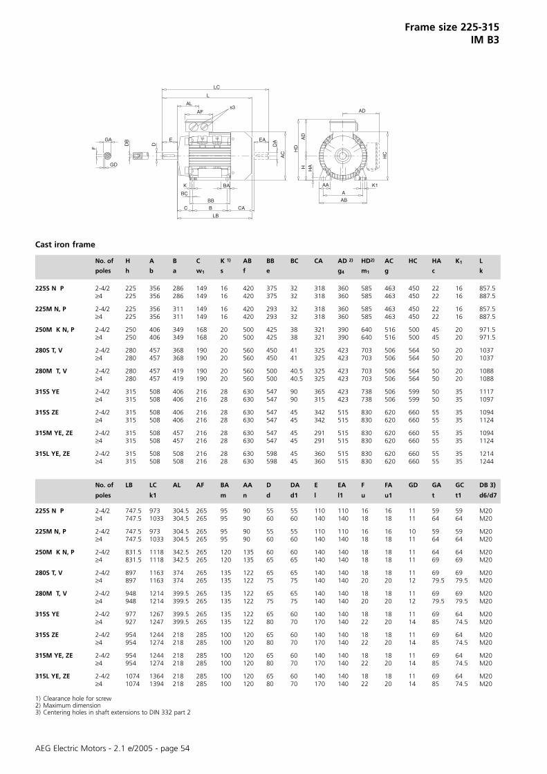
AEG Electric Motors - 2.1 e/2005 - page 54
Frame size 225-315IM B3
No. of H A B C K 1) AB BB BC CA AD 2) HD2) AC HC HA K1 L
poles h b a w1 s f e g4 m1 g c k
225S N P 2-4/2 225 356 286 149 16 420 375 32 318 360 585 463 450 22 16 857.5≥4 225 356 286 149 16 420 375 32 318 360 585 463 450 22 16 887.5
225M N, P 2-4/2 225 356 311 149 16 420 293 32 318 360 585 463 450 22 16 857.5≥4 225 356 311 149 16 420 293 32 318 360 585 463 450 22 16 887.5
250M K N, P 2-4/2 250 406 349 168 20 500 425 38 321 390 640 516 500 45 20 971.5≥4 250 406 349 168 20 500 425 38 321 390 640 516 500 45 20 971.5
280S T, V 2-4/2 280 457 368 190 20 560 450 41 325 423 703 506 564 50 20 1037≥4 280 457 368 190 20 560 450 41 325 423 703 506 564 50 20 1037
280M T, V 2-4/2 280 457 419 190 20 560 500 40.5 325 423 703 506 564 50 20 1088≥4 280 457 419 190 20 560 500 40.5 325 423 703 506 564 50 20 1088
315S YE 2-4/2 315 508 406 216 28 630 547 90 365 423 738 506 599 50 35 1117≥4 315 508 406 216 28 630 547 90 315 423 738 506 599 50 35 1097
315S ZE 2-4/2 315 508 406 216 28 630 547 45 342 515 830 620 660 55 35 1094≥4 315 508 406 216 28 630 547 45 342 515 830 620 660 55 35 1124
315M YE, ZE 2-4/2 315 508 457 216 28 630 547 45 291 515 830 620 660 55 35 1094≥4 315 508 457 216 28 630 547 45 291 515 830 620 660 55 35 1124
315L YE, ZE 2-4/2 315 508 508 216 28 630 598 45 360 515 830 620 660 55 35 1214≥4 315 508 508 216 28 630 598 45 360 515 830 620 660 55 35 1244
No. of LB LC AL AF BA AA D DA E EA F FA GD GA GC DB 3)
poles k1 m n d d1 l l1 u u1 t t1 d6/d7
225S N P 2-4/2 747.5 973 304.5 265 95 90 55 55 110 110 16 16 11 59 59 M20≥4 747.5 1033 304.5 265 95 90 60 60 140 140 18 18 11 64 64 M20
225M N, P 2-4/2 747.5 973 304.5 265 95 90 55 55 110 110 16 16 10 59 59 M20≥4 747.5 1033 304.5 265 95 90 60 60 140 140 18 18 11 64 64 M20
250M K N, P 2-4/2 831.5 1118 342.5 265 120 135 60 60 140 140 18 18 11 64 64 M20≥4 831.5 1118 342.5 265 120 135 65 65 140 140 18 18 11 69 69 M20
280S T, V 2-4/2 897 1163 374 265 135 122 65 65 140 140 18 18 11 69 69 M20≥4 897 1163 374 265 135 122 75 75 140 140 20 20 12 79.5 79.5 M20
280M T, V 2-4/2 948 1214 399.5 265 135 122 65 65 140 140 18 18 11 69 69 M20≥4 948 1214 399.5 265 135 122 75 75 140 140 20 20 12 79.5 79.5 M20
315S YE 2-4/2 977 1267 399.5 265 135 122 65 60 140 140 18 18 11 69 64 M20≥4 927 1247 399.5 265 135 122 80 70 170 140 22 20 14 85 74.5 M20
315S ZE 2-4/2 954 1244 218 285 100 120 65 60 140 140 18 18 11 69 64 M20≥4 954 1274 218 285 100 120 80 70 170 140 22 20 14 85 74.5 M20
315M YE, ZE 2-4/2 954 1244 218 285 100 120 65 60 140 140 18 18 11 69 64 M20≥4 954 1274 218 285 100 120 80 70 170 140 22 20 14 85 74.5 M20
315L YE, ZE 2-4/2 1074 1364 218 285 100 120 65 60 140 140 18 18 11 69 64 M20≥4 1074 1394 218 285 100 120 80 70 170 140 22 20 14 85 74.5 M20
1) Clearance hole for screw2) Maximum dimension3) Centering holes in shaft extensions to DIN 332 part 2
s3
BC
HC
AD
AB
A
K1
HD
AD
HAH
DAEA
AC
CA
AA
L
LC
AF
AL
E
D
BA
B
BB
LB
K
C
F
DBGA
GD
Cast iron frame

AEG Electric Motors - 2.1 e/2005 - page 55
IEC M N P T LA S1) H A B C K CA AD2) HD2) AC
DIN e1 b1 a1 f1 c1 s1 h b a w1 s g
56Z AA, BA 100 80 120 2.5 5.5 M6 56 90 71 36 6 65 98 154 112
63Z AA, BA, CA 115 95 140 3 10 M8 63 100 80 40 7 72 103 166 125
71Z AA, BA, CA 130 110 160 3.5 10 M8 71 112 90 45 7 86 112 183 142
80Z AA, BA, CA 165 130 200 3.5 10 M10 80 125 100 50 9 89 129 209 160
90S AA, BA 165 130 200 3.5 12 M10 90 140 100 56 10 113 138 228 18090L CA, DA 165 130 200 3.5 12 M10 90 140 125 56 10 88 138 228 180
100L AA, BA, CA 215 180 250 4 14 M12 100 160 140 63 11 110 145 245 196
112M AA, BA, CA 215 180 250 4 11 M12 112 190 140 70 10 126 161 273 225
132S AA, BA, YA, ZA 265 230 300 4 12 M12 132 216 140 89 10 147.5 198 330 270132M BA, CA, YA, ZA, RA 265 230 300 4 12 M12 132 216 178 89 10 147.5 198 330 270132M TA 265 230 300 4 12 M12 132 216 178 89 10 197.5 198 330 270
160M XA, VA, ZA 300 250 350 5 13 M16 160 254 210 108 12 192 246 406 335160L RA, XA, ZA 300 250 350 5 13 M16 160 254 254 108 12 192 246 406 335
180M RA, XA 300 250 350 5 13 M16 180 279 241 121 12 256 266 446 366180L RA, XA 300 250 350 5 13 M16 180 279 279 121 12 218 266 446 366
BC HA HC K1 L LB LC AL AF D/DA E/EA F/FA GD GA/GC DB3)
c k k1 d/d1 l/l1 u/u1 t,t1 d6/d7
56Z AA, BA 9.5 8 110 12 190 170 211 63 89 9 20 3 3 10.2 M4
63Z AA, BA, CA 12.5 8 125 12 213 190 238 66 89 11 23 4 4 12.5 M4
71Z AA, BA, CA 9.5 9 142 17 245 215 278 75 89 14 30 5 5 16 M5
80Z AA, BA, CA 12.5 9.5 162 14 272 232 319 79 116 19 40 6 6 21.5 M6
90S AA, BA 25 11 181 15 317 267 372 85 116 24 50 8 7 27 M890L CA, DA 12.5 11 181 15 317 267 372 85 116 24 50 8 7 27 M8
100L AA, BA, CA 13 12 198 17 366 306 433 91 116 28 60 8 7 31 M10
112M AA, BA, CA 17.5 15 226 19 388 328 456 91.5 116 28 60 8 7 31 M10
132S AA, BA, YA, ZA 17.5 20 262 14 449.5 369.5 536.5 134 133 38 80 10 8 41 M12132M BA, CA, YA, ZA, RA 18.5 20 262 14 487.5 407.5 574.5 134 133 38 80 10 8 41 M12132M TA 18.5 20 262 14 537.5 457.5 624.5 134 133 38 80 10 8 41 M12
160M XA, VA, ZA 20 20 324 14 613 503 730 156 149 42 110 12 8 45 M16160L RA, XA, ZA 20 20 324 14 657 547 774 156 149 42 110 12 8 45 M16
180M RA, XA 22.5 22 360 18 712 602 838 178.5 180 48 110 14 9 51.5 M16180L RA, XA 22.5 22 360 18 712 602 838 178.5 180 48 110 14 9 51.5 M16
1) Clearance hole for screw2) Maximum dimension3) Centering holes in shaft extensions to DIN 332 part 2
Frame size 56 - 180IM B5, IM B35, IM V1
Aluminium frame
AD
AD
AA
AB
BA
BB
F
GA
GD
M
S
T
NP
LA
EAD
HD
HAH
ACA
K1
BC
K
DAEA
AC
L
LC
AF
AL
EDLB
DB

AEG Electric Motors - 2.1 e/2005 - page 56
IEC M N P T LA S1) H A B C K CA AD2) HD2) AC
DIN e1 b1 a1 f1 c1 s1 h b a w1 s g
132S YG, ZG 265 230 300 4 12 M12 132 216 140 89 10 185.5 201 333 270132M YG, ZG, RG 265 230 300 4 12 M12 132 216 178 89 10 147.5 201 333 270132M TG 265 230 300 4 12 M12 132 216 178 89 10 197.5 201 333 270
160M VG, XG, ZG 300 250 350 5 13 M16 160 254 210 108 12 226 250 410 335160L RG, XG, ZG 300 250 350 5 13 M16 160 254 254 108 12 192 250 410 335
180M RG, XG 300 250 350 5 13 M16 180 279 241 121 12 256 290 470 366180L RG, XG, ZG 300 250 350 5 13 M16 180 279 279 121 12 218 290 470 366
200L LG, NG, PG, RG, FG 350 300 400 5 15 M16 200 318 305 133 16 237 341 541 405
BC HA HC K1 L LB LC AL AF D/DA E/EA F/FA GD GA/GC DB3)
c k k1 d/d1 l/l1 u/u1 t,t1 d6/d7
132S YG, ZG 17.5 20 262 14 487.5 407.5 574.5 134 133 38 80 10 8 41 M12132M YG, ZG, RG 18.5 20 262 14 487.5 407.5 574.5 134 133 38 80 10 8 41 M12132M TG 18.5 20 262 14 537.5 457.5 624.5 134 133 38 80 10 8 41 M12
160M VG, XG, ZG 18 15 324 14 657 547 774 235 168 42 110 12 8 45 M16160L RG, XG, ZG 18 15 324 14 657 547 774 235 168 42 110 12 8 45 M16
180M RG, XG 22.5 15 360 18 712 602 838 260.5 180 48 110 14 9 51.5 M16180L RG, XG, ZG 22.5 15 360 18 712 602 838 260.5 180 48 110 14 9 51.5 M16
200L LG, NG, PG, RG, FG 27.5 18 400 _ 779 669 895 185.5 265 55 110 16 9 59 M20
1) Clearance hole for screw2) Maximum dimension3) Centering holes in shaft extensions to DIN 332 part 2
Frame size 132 - 200IM B5, IM B35, IM V1
Cast iron frame
AD
AD
AA
AB
BA
BB
F
GA
GD
M
S
T
NP
LA
EAD
HD
HAH
ACA
K1
BC
K
DAEA
AC
L
LC
AF
AL
ED
LB
DB

AEG Electric Motors - 2.1 e/2005 - page 57
Frame size 225 - 315IM B5, IM B35, IM V1
AD
AD
AB
AABA
BB
SM
DA
AC
EA
K1
HD
HAH
A
AD
LC
L
AF
LB
T
E
E
D
P N
AL
LA
GA
GD
DB
F
B
K
C CA
45∞
22.5∞
No. of M N P T LA S1) H A B C K CA HD2) AC AD2) HA K1
poles e1 b1 a1 f1 c1 s1 h b a w1 s m1 g g4 c
225S N, P 2-4/2 400 350 450 5 16 M16 225 356 286 149 16 318 585 463 360 22 16≥4 400 350 450 5 16 M16 225 356 286 149 16 318 585 463 360 22 16
225M N, P 2-4/2 400 350 450 5 16 M16 225 356 311 149 16 293 585 463 360 22 16≥4 400 350 450 5 16 M16 225 356 311 149 16 293 585 463 360 22 16
250M K, N, P 2-4/2 500 450 550 5 18 M16 250 406 349 168 20 321 640 516 390 45 20≥4 500 450 550 5 18 M16 250 406 349 168 20 321 640 516 390 45 20
280S T, V 2-4/2 500 450 550 5 18 M16 280 457 368 190 20 325 703 514 423 50 20≥4 500 450 550 5 18 M16 280 457 368 190 20 325 703 514 423 50 20
280M T, V 2-4/2 500 450 550 5 18 M16 280 457 419 190 20 325 703 514 423 50 20≥4 500 450 550 5 18 M16 280 457 419 190 20 325 703 514 423 50 20
315S YE 2-4/2 600 550 660 6 22 M20 315 508 406 216 28 365 738 514 423 50 35≥4 600 550 660 6 22 M20 315 508 406 216 28 315 738 514 423 50 35
315S ZE 2-4/2 600 550 660 6 22 M20 315 508 406 216 28 342 830 620 515 55 35≥4 600 550 660 6 22 M20 315 508 406 216 28 342 830 620 515 55 35
315M YE, ZE 2-4/2 600 550 660 6 22 M20 315 508 457 216 28 291 830 620 515 55 35≥4 600 550 660 6 22 M20 315 508 457 216 28 291 830 620 515 55 35
315L YE, ZE * 2-4/2 600 550 660 6 22 M20 315 508 508 216 28 360 830 620 515 55 35≥4 600 550 660 6 22 M20 315 508 508 216 28 360 830 620 515 55 35
No. of L LB LC AL AF BC D DA E EA F FA GD GA GC DB3)
poles k k1 d d 1 I I1 u u1 t t1 d6/d7
225S N, P 2-4/2 857.5 747.5 973 304.5 265 32 55 55 110 110 16 16 11 59 59 M 20≥4 887.5 747.5 1033 304.5 265 32 60 60 140 140 18 18 11 64 64 M 20
225M N, P 2-4/2 857.5 747.5 973 304.5 265 32 55 55 110 110 16 16 10 59 59 M 20≥4 887.5 747.5 1033 304.5 265 32 60 60 140 140 18 18 11 64 64 M 20
250MK, P 2-4/2 971.5 831.5 1118 342.5 265 38 60 60 140 140 18 18 11 64 64 M 20≥4 971.5 831.5 1118 342.5 265 38 65 65 140 140 18 18 11 69 69 M 20
280S T, V 2-4/2 1037 897 1163 374 265 41 65 65 140 140 18 18 11 69 69 M 20≥4 1037 897 1163 374 265 41 75 75 140 140 20 20 12 79.5 79.5 M 20
280M T, V 2-4/2 1088 948 1214 399.5 265 40.5 65 65 140 140 18 18 11 69 69 M 20≥4 1088 948 1214 399.5 265 40.5 75 75 140 140 20 20 12 79.5 79.5 M 20
315S YE 2-4/2 1117 977 1267 399.5 265 90 65 60 140 140 18 18 11 69 64 M 20≥4 1097 927 1247 399.5 265 90 80 70 170 140 22 20 14 85 74.5 M 20
315S ZE 2-4/2 1094 954 1244 218 285 45 65 60 140 140 18 18 11 69 64 M 20≥4 1124 954 1274 218 285 45 80 70 170 140 22 20 14 85 74.5 M 20
315M YE, ZE 2-4/2 1094 954 1244 218 285 45 65 60 140 140 18 18 11 69 64 M 20≥4 1124 954 1274 218 285 45 80 70 170 140 22 20 14 85 74.5 M 20
315L YE, ZE * 2-4/2 1214 1074 1364 218 285 45 65 60 140 140 18 18 11 69 64 M 20≥4 1244 1074 1394 218 285 45 80 70 170 140 22 20 14 85 74.5 M 20
1) Clearance hole for screw2) Maximum dimension3) Centering holes in shaft extensions to DIN 332 part 2
* IM B5 on request
Cast iron frame

AEG Electric Motors - 2.1 e/2005 - page 58
Frame size 56 - 160IM B14, IM B34
AD
AD
AD
AB
AABA
BB
GA
GD
F
NP
S
M
A
H HA
K1
HD
DA
AC
EA
L
AF
AL
T
E
LC
DDB
CA
LB
LA
E
BC
K
Small flange Large flangeP N LA M T S P N LA M T S L LB LC AL AF D DA BCa1 b1 c1 e1 f1 s1 a1 b1 c1 e1 f1 s1 k k1 d d1
56Z AA, BA 80 50 65 3 M5 105 70 8 85 2.5 M6 190 170 211 63 89 9 9 9.5
63Z AA, BA, CA 90 60 75 2.5 M5 120 80 8 100 2.5 M6 213 190 238 66 89 11 11 12.5
71Z AA, BA, CA 105 70 85 2.5 M6 140 95 8 115 2.5 M8 245 215 278 75 89 14 14 9.5
80Z AA, BA, CA 120 80 8 100 3 M6 160 110 8.5 130 3.5 M8 272 232 319 79 116 19 19 12.5
90S AA, BA 140 95 10 115 3 M8 160 110 9 130 3.5 M8 317 267 372 85 116 24 24 2590L BA, CA, DA 140 95 10 115 3 M8 160 110 9 130 3.5 M8 317 267 372 85 116 24 24 12.5
100L AA, BA, CA 160 110 10 130 3.5 M8 200 130 12 165 3.5 M10 366 306 433 91 116 28 28 13
112M AA, BA, CA 160 110 10 130 3.5 M8 200 130 12 165 3.5 M10 388 328 456 91.5 116 28 28 17.5
132S AA, BA, YA, ZA 200 130 12 165 3.5 M10 250 180 12 215 4 M12 449.5 369.5 536.5 134 133 38 38 17.5132M BA,CA,YA,ZA,RA 200 130 12 165 3.5 M10 250 180 12 215 4 M12 487.5 407.5 574.5 134 133 38 38 18.5132M TA 200 130 12 165 3.5 M10 250 180 12 215 4 M12 537.5 457.5 624.5 134 133 38 38 18.5
160M XA, VA, ZA 4) 250 180 12 215 4 M12 300 230 12 265 5 M16 613 503 730 156 149 42 42 20160L RA, XA, ZA 4) 250 180 12 215 4 M12 300 230 12 265 5 M16 657 547 774 156 149 42 42 20
E EA F FA GD GA GC DB3) H A B C K1) AB BB CA AD2) HD2) AC HC HA K1
I l1 u u1 t/t1 d6/d7 h b a w1 s f e g4 m1 g c
56Z AA, BA 20 20 3 3 3 10.2 10.2 M4 56 90 71 36 6 109 90 65 98 154 112 110 8 12
63Z AA, BA, CA 23 23 4 4 4 12.5 12.5 M4 63 100 80 40 7 126 105 72 103 166 125 125 8 12
71Z AA, BA, CA 30 30 5 5 5 16 16 M5 71 112 90 45 7 144 109 86 112 183 142 142 9 17
80Z AA, BA, CA 40 40 6 6 6 21.5 21.5 M6 80 125 100 50 9 153 125 89 129 209 160 9.5 14 14
90S AA, BA 50 50 8 8 7 27 27 M8 90 140 100 56 10 170 150 113 138 228 180 181 11 1590L BA, CA, DA 50 50 8 8 7 27 27 M8 90 140 125 56 10 170 150 88 138 228 180 181 11 15
100L AA, BA, CA 60 60 8 8 7 31 31 M10 100 160 140 63 11 192 166 110 145 245 196 198 12 17
112M AA, BA, CA 60 60 8 8 7 31 31 M10 112 190 140 70 10 220 175 126 161 278 225 226 15 19
132S AA, BA, YA, ZA 80 80 10 10 8 41 41 M12 132 216 140 89 10 260 175 147.5 198 330 270 262 20 14132M BA CA, YA, ZA, RA 80 80 10 10 8 41 41 M12 132 216 178 89 10 260 215 147.5 198 330 270 262 20 14132M TA 80 80 10 10 8 41 41 M12 132 216 178 89 10 260 215 197.5 198 330 270 262 20 14
160M XA, VA, ZA 4) 110 110 12 12 8 45 45 M16 160 254 210 108 12 292 250 192 246 406 335 324 20 14160L RA, XA, ZA 4) 110 110 12 12 8 45 45 M16 160 254 254 108 12 292 294 192 246 406 335 324 20 14
1) Clearance hole for screw2) Maximum dimension3) Centering holes in shaft extensions to DIN 332 part 24) Bearing drive end 6309 2Z C3
Aluminium frame

AEG Electric Motors - 2.1 e/2005 - page 59
Frame size 132 - 160IM B14, IM B34
AD
AD
AD
AB
AABA
BB
GA
GDF
NP
S
M
A
H HA
K1
HD
DA
AC
EA
L
AF
AL
T
E
LC
DDB
CA
LB
LA
E
BC
K
Small flange Large flangeP N LA M T S P N LA M T S L LB LC AL AF D DA BC
a1 b1 c1 e1 f1 s1 a1 b1 c1 e1 f1 s1 k k1 d d1
132S YG, ZG 200 130 12 165 3.5 M10 250 180 12 215 4 M12 449.5 369.5 536.5 134 133 38 38 17.5132M YG, ZG, RG 200 130 12 165 3.5 M10 250 180 12 215 4 M12 487.5 407.5 574.5 134 133 38 38 18.5132M TG 200 130 12 165 3.5 M10 250 180 12 215 4 M12 537.5 457.5 624.5 134 133 38 38 18.5
160M VG, XG, ZG 250 180 12 215 4 M12 300 230 12 265 5 M16 613 503 730 235 168 42 42 18160L RG, XG, ZG 250 180 12 215 4 M12 300 230 12 265 5 M16 657 547 774 235 168 42 42 18
E EA F FA GD GA GC DB3) H A B C K1) AB BB CA AD2) HD2) AC HC HA K1
I l1
u u1
t/t1
d6/d
7h b a w
1s f e g
4m
1g c
132S YG, ZG 80 80 10 10 8 41 41 M12 132 216 140 89 10 260 175 185.5 201 333 270 262 20 14132M YG, ZG, RG 80 80 10 10 8 41 41 M12 132 216 178 89 10 260 215 147.5 201 333 270 262 20 14132M TG 80 80 10 10 8 41 41 M12 132 216 178 89 10 260 215 197.5 201 333 270 262 20 14
160M VG, XG, ZG 110 110 12 12 8 45 45 M16 160 254 210 108 12 304 290 226 250 410 335 324 15 14160L RG, XG, ZG 110 110 12 12 8 45 45 M16 160 254 254 108 12 304 290 192 250 410 335 324 15 14
1) Clearance hole for screw2) Maximum dimension3) Centering holes in shaft extensions to DIN 332 part 2
Cast iron frame

AEG Electric Motors - 2.1 e/2005 - page 60
Notes. . . . . . . . . . . . . . . . . . . . . . . . . . . . . . . . . . . . . . . . . . . . . . . . . . . . . . . . . . . . . . . . . . . . . . . . . . . . . . . . .. . . . . . . . . . . . . . . . . . . . . . . . . . . . . . . . . . . . . . . . . . . . . . . . . . . . . . . . . . . . . . . . . . . . . . . . . . . . . . . .

Ital
iana
di C
omun
icaz
ione
AEG Electric Motors, S.A.P.I. Can PetitCarrer del Camí Fontde les Canyes, 45E - 08227 Terrassa(Barcelona) - SpainTel. +34 / 93 7398 400Fax +34 / 93 7398 [email protected]
Lafert S.p.A.Via J.F. Kennedy, 43I - 30027 San Donà di PiaveVenezia - ItalyTel. +39 / 0421 229 611Fax +39 / 0421 222 [email protected]
www. lafer t .com
Factories
AEG Electric Motors Ltd.Electra House - Electra WayCrewe, Cheshire CW1 6GLUnited KingdomPhone +44 / (0) 1270 270 022Fax +44 / (0) 1270 270 [email protected]
Lafert Motores Eléctricos, S.L.Polígono Pignatelli, Nave 27E - 50410 Cuarte de Huerva(Zaragoza) - SpainTel. +34 / 976 503 822Fax +34 / 976 504 [email protected]
Lafert Electric Motors (Australia)1676 Centre RoadAUS - Springvale VIC 3171 - AustraliaTel. +61 / (03) 9546 7515Fax +61 / (03) 9547 [email protected]
Lafert GmbHAEG Electric MotorsStuttgarter Str. 10D - 71032 Böblingen - GermanyTel. +49 / (0) 7031/410 73 - 0Fax +49 / (0) 7031/410 73 - [email protected]
Lafert Moteurs S.A.L’Isle d’Abeau Parc de Chesnes75, rue de MalacombeF - 38070 St. Quentin-FallavierFranceTel. +33 / 474 95 41 01Fax +33 / 474 94 52 [email protected]
Lafert N.A. (North America)5620 Kennedy Road - Mississauga,Ontario L4Z 2A9 - CanadaTel. +1 / 800/661 6413 - 905/629 1939Fax +1 / 905/629 [email protected]
Lafert Singapore Pte Ltd48 Hillview Terrace #03-08Hillview Building - Singapore 669269Tel. +65 / 67630400 - 67620400Fax +65 / [email protected]
Branches & Partners