ENGINEER’S TO LOW VOLUME INJECTION … VOLUME INJECTION MOLDING BY RONALD HOLLIS, Ph.D., ... and...
17
TOP STRATEGIES TO HELP YOU TAKE FULL ADVANTAGE OF THE LVIM PROCESS AN ENGINEER’S GUIDE TO LOW VOLUME INJECTION MOLDING BY RONALD HOLLIS, Ph.D., P.E. This eBook contains expert analysis on Low Volume Injection Molding, including all of the basics you need to get yourself up to speed on fully understanding the process. As well as insider benefits and tips for getting the most out of LVIM, this books contains the 6 step process that will get your products to market fastest and the issues and limitations of LVIM.
-
Upload
truongtruc -
Category
Documents
-
view
227 -
download
3
Transcript of ENGINEER’S TO LOW VOLUME INJECTION … VOLUME INJECTION MOLDING BY RONALD HOLLIS, Ph.D., ... and...

TOP STRATEGIES TO HELP YOU TAKE FULL ADVANTAGE OF THE LVIM PROCESS
AN ENGINEER’SGUIDE TOLOW VOLUMEINJECTION MOLDING BY RONALD HOLLIS, Ph.D., P.E.
This eBook contains expert analysis
on Low Volume Injection Molding,
including all of the basics you need
to get yourself up to speed on fully
understanding the process. As well as
insider benefits and tips for getting the
most out of LVIM, this books contains
the 6 step process that will get your
products to market fastest and the
issues and limitations of LVIM.

LOW-VOLUME INJECTION MOLDINGTO BRIDGE OR NOT TO BRIDGE
As with most things in life, folks tend to focus on the end
game, the score, the finale, but choose to ignore the many
critical steps and decisions that are made during the journey.
DEFINITION
Low-Volume Injection Molding
(LVIM) is a manufacturing method
that creates injection molds or tools
to produce functional parts from
thermoplastic in short runs of up to
typically 50,000 parts. Significantly
faster and cheaper, LVIM offers the
same quality, accuracy, and tol-
erance as production tooling, but
without 2D drawings.
WHY YOU NEED IT
To reduce wait time; to compress
production time; to make parts
while your production tool is being
produced; and to deliver parts to
your customer in two to four weeks,
instead of eight to twelve weeks with
a standard production tool.
IDEAL USES
Simple, single-cavity tools; a
“bridge tool” in aggressive product
development schedules; low-volume
requirements for applications with
a short lifespan; and is sometimes
used to test heat-resistance and
functionality in end-use materials.
02 | MFG.com | An Engineer’s Guide to Low Volume Injection Molding

LO W - V O LU M E I N J E C T I O N M O L D I N G B A S I C S
Stereolithography (SL), Selective Laser Sintering (SLS), Fused Deposition Modeling (FDM), Cast Urethane (CU),
and Computer Numerically Controlled (CNC) machining are all fabrication processes are all used to verify that
a design represents the intent of a product. Now it’s time to get tooling made. From tooling, you will produce
end-use plastic parts. Your choices are LVIM, production tooling, or a combination of both.
LVIM has existed as long as production tooling, well over a hundred years. In 1868, John Wesley Hyatt, a US in-
ventor with hundreds of patents, was the first to inject hot celluloid material into a mold to produce billiard balls.
He was looking for an alternative material to traditional ivory. The injection-molding process remained the same
until 1946 when the first screw injection molding machine revolutionized the plastics industry. Today, almost all
molding machines use screw injection molding to heat and inject plastic into tools or molds.
An Engineer’s Guide to Low Volume Injection Molding | MFG.com | 03
QUICK TIP: The labels “tool” “mold” ”mould,” “molding,” and “moulding” are all used
interchangeably throughout the industry, causing great consternation to outsiders. Similarly, a
“tool maker,” a “mold maker,” and a “mould maker” all make the tool. Additionally, a “molder,”
a “processor,” and an “injection molder,” make the parts. It’s all good!

Additionally, LVIM typically does not have as many
moving parts, actions, or features as a more com-
plex production tool. Lastly, LVIM is typically made
of aluminum or soft steel, requiring two to four
weeks to make, while production tools are typically
made of high-quality steel, and are deliverable in
eight or more weeks. This key difference in delivery
times makes LVIM a priceless “bridge tool” tech-
nology, enabling part delivery much earlier than the
production tool.
QUICK TIP: Injection molding is the
most common manufacturing method
for making plastic parts. A tool maker
creates the tool from steel or aluminum.
Under high pressure, molten plastic is
injected into the metal “tool” or mold
cavity, filling the inverse or negative
space to make a positive-shaped part.
04 | MFG.com | An Engineer’s Guide to Low Volume Injection Molding
CO N T R A S T I N G LO W - V O LU M E TO P R O D U C T I O N TO O L I N G
The term “Low-Volume Injection Molding” means different things to different people. To a designer, it may be a
tool that is used to make a relatively small number of parts. To a tool maker, it may be a tool that has been built
to demonstrate a strategy for making the production tool for a complicated part and to verify if it will perform
as anticipated. In the current world of product development, the use of LVIM is a critical strategy to expedite
development and to verify if it will perform as anticipated. In the current world of product development, the use
of LVIM is a critical strategy to expedite development. By leveraging the advantages of injection molding, the
developer is able to get his or her product to market faster without jeopardizing the result or increasing risk of
failure in the complicated world of production tooling.
Knowing the key differentiators between LVIM and production tooling will help you make decision tradeoffs as
your product moves forward into the most critical and expensive phase of manufacturing. Being lower in cost
and much faster to produce, LVIM means that you can get your product to market faster. The simplicity of the
LVIM—usually a single-cavity design—allows faster creation, whereas a production tool with many cavities
takes much longer to build. Low-Volume Injection Molds have a short life span and can withstand making up to
50,000 parts, while production tools live a long time and have the strength and durability to make millions of
parts. In low-volume production, the design goal is to keep the tool simple and use manpower to help process
the parts since the volumes are lower. In production, the tool is designed to be mostly automatic which
reduces the cost per part. LVIM typically does not need water lines; however, production tooling does require
water lines for cooling and would be included if it were to validate a tool design. Water lines add complexity,
time, and expense to the production tooling proces.

B E N E F I T S — T H E B U Z Z I S R E A L
In defining your best strategy for compressing product timelines, consider the benefits of LVIM. Product
developers are catching on to its powerful bridging capacity used to bolster the front end of larger
production projects. LVIM provides the only solution for creating a few real parts for functionality
testing in the end-use material. This short-run tool is priceless when it comes to garnering investors in early
market evaluations. Using LVIM as insurance provides additional safety to your bottom line.
An Engineer’s Guide to Low Volume Injection Molding | MFG.com | 05
LV I M A P P L I C AT I O N S E V E R Y T H I N G I S E V E R Y T H I N G
Look around you. Practically everything is an injection-molded part. If you tear apart any of your handheld
gadgets—cell phone, tape recorder, computer mouse, electric toothbrush—you will discover a multitude of
injection-molded thermoplastic parts. From the handle on your lawn mower to the produce drawer of your
refrigerator to the buttons on your radio, you sit at the center of a plastic injection-molded universe.
06 | MFG.com | Engineer’s Guide to Low Volume Injection Molding | The Basics
Short Run Needs
Product developers use LVIM for short run needs
when they need a few thousand parts to get
the product to market. Since the LVIM process
is fast and cost-effective, it’s a great way to get
low volumes of parts in the end-use material and
beat your competitor to market. LVIM is useful in
many situations in which you may not be sure of
the market’s demand for your product. It’s also
useful if you’re still trying to overcome design
or technical challenges. Essentially, an injection
mold is a dispensable or disposable tool that has
the sole purpose of creating a few parts that look
like the production parts. LVIM is commonly used for
short runs in medical and industrial sectors, situations
in which the product already has a very low-volume
requirement and may have many phases of iterations
planned into the design. These application types
require much process flexibility and the ability to get
parts fast and economically. Short run applications do
not require a production level tool to meet the needs
of the product.
Real Functionality Testing
Product developers use LVIM to get a real, func-
tional test unit to verify the product by getting parts
made from the specified thermoplastic material.
Rapid prototyping processes would not work be-
cause they do not produce parts in end-use materi-
als. LVIM represents an amazing advance in the way
products are developed. Not only does it allow the
prototyping of parts in the actual end-use material,
but also the parts are made in a similar process as
the final production parts. Therefore, you are getting
an excellent test of how your actual parts will look
off the production line. Using LVIM is a very com-
mon requirement in areas in which the part will be
used in harsh environments, high temperatures, or
at high loads. Product development teams need to
know exactly how that part will react, but they don’t
want to invest the time or money required for a pro-
duction tool that will need to be replaced. This process
allows them to gather new information in prototype
testing before investing in production tooling. While
the production tooling approach is a very expensive
way to develop a product, in some situations it is un-
avoidable as there is no other way to actually produce
the product and assimilate injection molding without
the final process. With the use of LVIM in today’s
world, the cost is very reasonable and the time
significantly reduced.
06 | MFG.com | An Engineer’s Guide to Low Volume Injection Molding
Bridge to Production
Product developers use LVIM as a “bridge tool” or
transition to get some of the product to market while their
production tooling is being made. LVIM can be a very
powerful way to augment a product development strategy.
As engineers know, many unknowns and potential risks
to the schedule can occur when the production tooling
process gets started. Bridge tooling makes it possible to
mitigate the risk associated with the production
tooling schedule when an LVIM is made in parallel with the
production tool. The product development company can
have the latest version of the product started with an LVIM,
which typically takes two to four weeks to process. At the
same time, the mold maker starts the production tooling
process for the same part. By the time the LVIM is done,
the design for the production tooling is well on its way—
the CNC is ready to start cutting a block of aluminum into
the core and cavity of the production tool. The product de-
velopment company can then begin assembling parts and
shipping products to market while their production tooling
is being produced—all without risking any schedules or
forcing the production schedule to be more aggressive
than it needs to be.
Insurance
Product developers also use LVIM as a backup when they
are not certain of production tooling schedules. Often used
as “insurance,” LVIM is needed when the product develop-
er is developing a complicated part, using an exotic mate-
rial, or trying a new supplier. By leveraging the economics
and speed of the LVIM process, the product development
company can feel assured that it is fully leveraging the re-
sources available without risking the future of the product.
Like insurance, LVIM covers the risk associated with the
challenges of the product.
Market Evaluation
Product developers use LVIM to assess the product
prior to investor commitments. The use of LVIM is an
excellent way to evaluate the market for a product. It
is not uncommon for a product to go to market and be
ergonomically unacceptable to the consumer if features
are inaccessible to the user. The LVIM process allows
product development companies to get real-world data
on their product before investing heavily in a production
tool that can produce millions of parts. With this valu-
able marketing feedback, companies can fine-tune their
design to perfection so that when they do go to market,
product success is guaranteed.
T H E K E Y S TO A B R A N D N E W A M P H I B I O U S
By now you know that LVIM is a manufacturing method that creates mostly aluminum tooling or injection
molds for producing short runs of up to 50,000 parts. Hopefully you’ve also been inspired to try LVIM as a
“bridge tool.” You’ve felt the technological excitement of seeing how LVIM can compress production time and
get parts for evaluation early in the process. You understand that LVIM provides powerful insurance on very
costly projects. You’ve seen the world of manufacturing turned upside down and you now understand the
winning strategy is called the Hybrid Manufacturing Solution. Enjoy the chaos.
An Engineer’s Guide to Low Volume Injection Molding | MFG.com | 07

INDUSTRY OVERVIEW — A NERD’S EYE VIEW OF LVIM
With current technologies and the growing acceptance of LVIM, applications of this process continue to expand, making LVIM a standard element of the product development process. Decades before LVIM, a production tool was predominantly focused on proving that a part could be molded successfully. In other words, product developers had to use full-on production tooling to validate a part; there was no intermediary refinement process to see how the part would “behave” in reality. But the LVIM process has evolved significantly with the use of CAD and CAM technologies. It is now considered a very useful technology in the iterative development process.
There are many ways of using this process to get your products to market faster. Product developers often use a “bridge tooling” strategy that includes both LVIM and production tooling, either in parallel or in sequence, to support their goals.
Applications for LVIM are found in every industry sector: industrial, automotive, medical, lawn and garden, and consumer electronics. Close tolerances and high-end appearance are ideal for today’s short run projects.
THE PROCESS OF MOLD MAKING
Making an LVIM is a fascinating process in which you create something to create something else. One of the major challenges in the process is that you must create a mold or tool that can be used as a receptacle for molten thermoplastic that holds the inverse or negative shape of the part you desire. While this sounds simple enough, some special knowledge is required.
Making the physical tool is just a piece of the battle. The part geometry you design must be conducive to the molding process, and the end-use material must be conducive to the part, as well as the mold. The many variables of the process — design, materials, actions, and expectations — make the process of getting from tooling to parts a challenge.
The more efficient LVIM process is similar to the tool making process in that it has existed for more than a hundred years. As with sculpting, the tool maker eliminates what is not required and keeps only what is essential.
08 | MFG.com | An Engineer’s Guide to Low Volume Injection Molding
Find the perfect supplier to fit your manufacturing needs today on MFG.com Log in and start sourcing today!

STEP BY STEP: MAKING A MOLD
Mold making is a complex science that requires a high level of expertise in design, materials, and physics, along with
artistic and intuitive insight, all part of the mold maker’s trade. A highly valued and specialized craftsman “begins
at the beginning.” He starts with a great plan for a well-designed part and follows through with flawless execution,
resulting in a very smooth, high-quality injection mold.
If those of you who are engineers are scratching your heads, you are not alone. For some reason, this valuable mold-
making module is not taught in engineering school, so here’s an important addition to every designer’s knowledge
base. Step by step, this is how you make a mold.
When designing a mold, make sure it is conducive
to injection molding. The design process for
plastic parts is critical, taking into account the
“moldability” of a shape. With today’s easy-to-
use CAD software in the hands of very “green”
designers, it is common for parts to be designed
that can be prototyped successfully with SL,
SLS, and FDM, and accepted by the customer.
However, these parts may yet still be unable to be
injection molded. This can often cost your company
thousands of dollars in errors, issues, and lost
opportunities.
Early in the process, the expert tool maker closely
considers all that could go wrong with a design.
Defects that result from poor design arise due to lack
of draft, parting line problems, poorly fitting ejector
pins, and poor materials selection, among other things.
Consequently, the next steps happen electronically in
CAD during your design process.
A) Assess the part for the injection-molding process or Design for Manufacturability (DFM)
PLAN HOW TO MAKE THE MOLD1
09 | MFG.com | An Engineer’s Guide to Low Volume Injection Molding
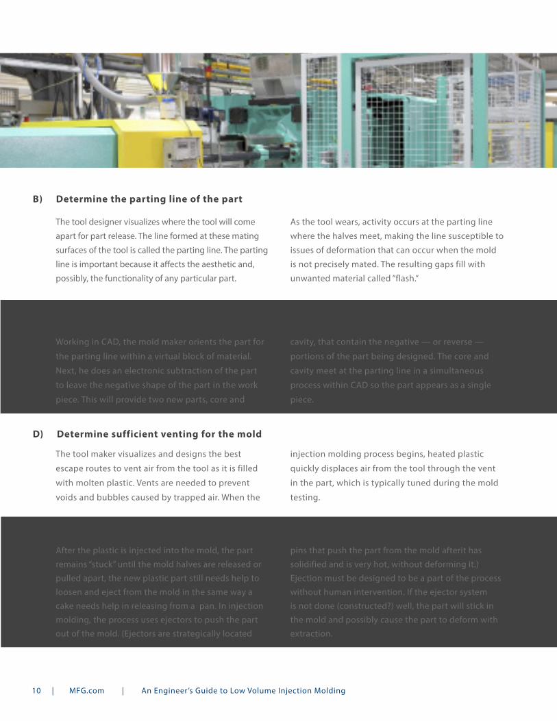
The tool designer visualizes where the tool will come
apart for part release. The line formed at these mating
surfaces of the tool is called the parting line. The parting
line is important because it affects the aesthetic and,
possibly, the functionality of any particular part.
As the tool wears, activity occurs at the parting line
where the halves meet, making the line susceptible to
issues of deformation that can occur when the mold
is not precisely mated. The resulting gaps fill with
unwanted material called “flash.”
B) Determine the parting line of the part
Working in CAD, the mold maker orients the part for
the parting line within a virtual block of material.
Next, he does an electronic subtraction of the part
to leave the negative shape of the part in the work
piece. This will provide two new parts, core and
cavity, that contain the negative — or reverse —
portions of the part being designed. The core and
cavity meet at the parting line in a simultaneous
process within CAD so the part appears as a single
piece.
C) Create the part negative from the mold halves
The tool maker visualizes and designs the best
escape routes to vent air from the tool as it is filled
with molten plastic. Vents are needed to prevent
voids and bubbles caused by trapped air. When the
injection molding process begins, heated plastic
quickly displaces air from the tool through the vent
in the part, which is typically tuned during the mold
testing.
D) Determine sufficient venting for the mold
After the plastic is injected into the mold, the part
remains “stuck” until the mold halves are released or
pulled apart, the new plastic part still needs help to
loosen and eject from the mold in the same way a
cake needs help in releasing from a pan. In injection
molding, the process uses ejectors to push the part
out of the mold. (Ejectors are strategically located
pins that push the part from the mold afterit has
solidified and is very hot, without deforming it.)
Ejection must be designed to be a part of the process
without human intervention. If the ejector system
is not done (constructed?) well, the part will stick in
the mold and possibly cause the part to deform with
extraction.
E) Determine the best ejection system for the mold
10 | MFG.com | An Engineer’s Guide to Low Volume Injection Molding

After the tool is electronically designed and all key decisions have been made, the machinist’s physical work begins. The CAM software technician processes the data for the mold halves to be machined with CNC, making the process very easy and versatile. Also, some features are processed with an Electrical Discharge Machine (EDM), which uses an electrical charge to burn away the excess, unwanted material.
Built on the same interrelated model as the CAD data, the CAM output will change automatically if the CAD data changes. High-speed CNC machines today can also cut metals faster, but the time advantage is incidental. The real power is in the CAM software and the CNC process.
MACHINE THE MOLD HALVES WITH CNC AND EDM2
After the mold halves have been completely processed and machined, the tool maker mates them together, a high-precision process. The end result must be very close to perfect, with no gaps or misalignments.
There are many tricks of the trade, such as an ink stamping process called “bluing, which is used to check for the transfer of ink to the other half of the mold to ensure full mating of mold halves. (An interesting side note is that the U.S. typically uses blue ink, while China typically uses red ink.) The critical need is for the surfaces to mate perfectly before continuing the process. If not, only expensive future rework can fix this error.
Mating has a major impact on the overall quality of the parts that come from the mold, and it can add extra “features” from the mismatch called “witness” lines. If a small gap between the two halves goes undetected, extra material will be squeezed into this gap, leaving obvious traces that may ruin the part. It is common that during the mating of the mold halves that the molds need to be polished so they are very smooth to produce the best parts. Polishing is a very time consuming process.
MATE THE HALVES FOR FIT3
11 | MFG.com | An Engineer’s Guide to Low Volume Injection Molding

Mold assembly is where a real time-drain can occur. After the mold halves have been completely mated, they are assembled with supporting hardware much like a 3D puzzle. Supporting hardware includes fitting every piece that is required to make the mold workable, such as ejector pins, actions, and alignment guides. By assembling the two halves with all hardware, the tool maker ensures that, for the first time, all pieces are available and assembled correctly. Time-drain can occur if parts of the mold have been forgotten or were incorrectly made, such as slides or lifters being too big or fitting too loose. A small but critical error like this stops all progress as the pieces are reworked.
ASSEMBLE THE MOLD4
INSTALL AND TEST THE NEW MOLD
MAKE PARTS FROM THE MOLD
5
6
The trial run with the injection-molding press is where the rubber meets the road. This step reveals whether all of your previous work comes together or falls apart. The molding processor takes over from the tool maker and hangs the mold in the press. He shoots hot plastic into the mold as a trial run to see how it performs. He hopes that a perfect replication of the part design will result, but this would be uncommon on the first trial,. the first shots are used to identify tooling problems or design issues. A plastic part stuck in the mold can mean many things, most likely that the ejection system is not working or there is not enough draft designed in. At this point, the tool maker’s “artistry” is required to diagnose the issues and make the required improvements to the mold. It is a challenge to predict how long it will take to get the mold just right.
Once validated, the mold is now production-ready. The operator installs the mold in the injection molding press. Plastic pellets are funneled from a hopper, then heated and forced under extreme pressure into the mold cavity. Within seconds, the injected plastic solidifies into the shape of the part. The mold then opens automatically and ejects the newly formed part. After the mold ejects the part, the process repeats.
12 | MFG.com | An Engineer’s Guide to Low Volume Injection Molding
Register Today!
Register with MFG.com to discover a secure solution for
all your sourcing needs
BORING BUT NECESSARY — LVIM ISSUES AND LIMITATIONS
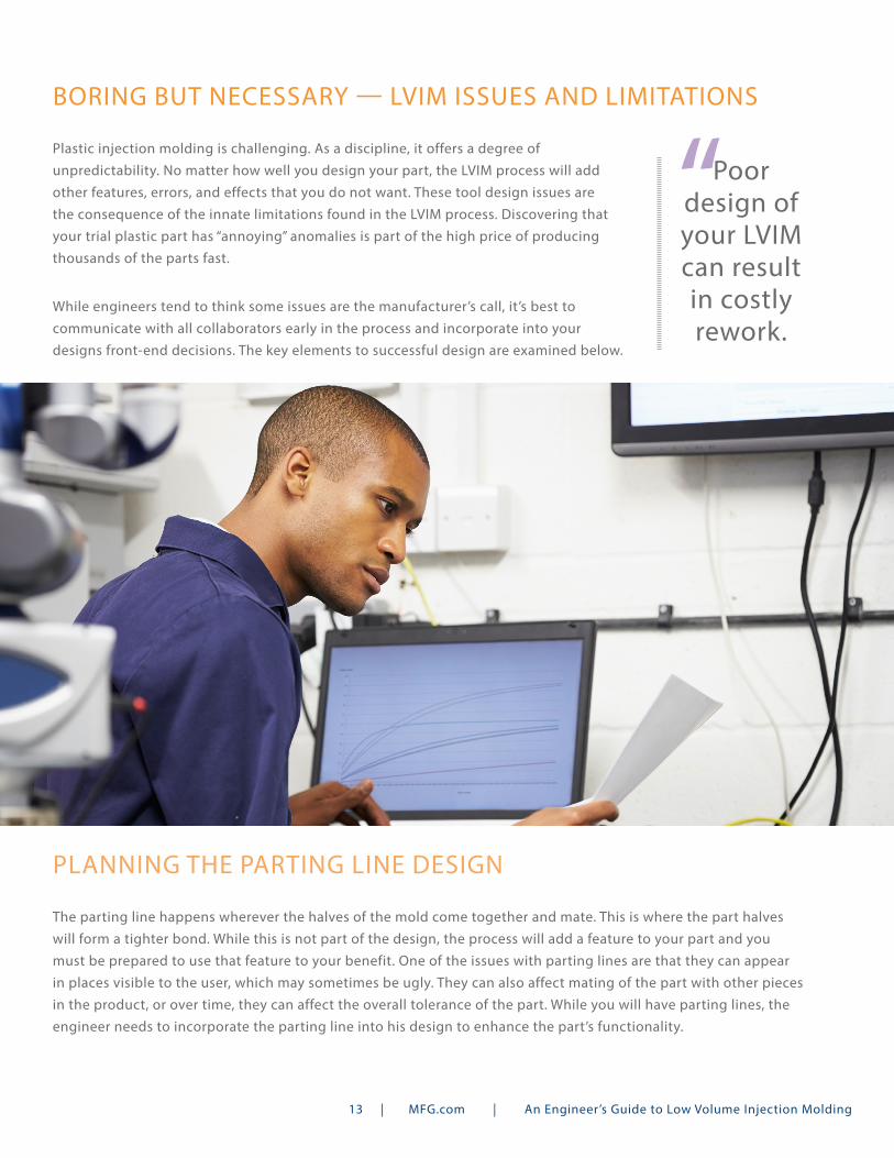
Plastic injection molding is challenging. As a discipline, it offers a degree of unpredictability. No matter how well you design your part, the LVIM process will add other features, errors, and effects that you do not want. These tool design issues are the consequence of the innate limitations found in the LVIM process. Discovering that your trial plastic part has “annoying” anomalies is part of the high price of producing thousands of the parts fast.
While engineers tend to think some issues are the manufacturer’s call, it’s best to communicate with all collaborators early in the process and incorporate into your designs front-end decisions. The key elements to successful design are examined below.
PLANNING THE PARTING LINE DESIGN
The parting line happens wherever the halves of the mold come together and mate. This is where the part halves will form a tighter bond. While this is not part of the design, the process will add a feature to your part and you must be prepared to use that feature to your benefit. One of the issues with parting lines are that they can appear in places visible to the user, which may sometimes be ugly. They can also affect mating of the part with other pieces in the product, or over time, they can affect the overall tolerance of the part. While you will have parting lines, the engineer needs to incorporate the parting line into his design to enhance the part’s functionality.
“Poor design of your LVIM can result in costly rework.
13 | MFG.com | An Engineer’s Guide to Low Volume Injection Molding
DRAFTING THE PART
Draft is the required slant or slope of the walls of the part touching the sides of the tool. Proper draft allows the part
to disengage quickly from the mold when the process is complete. Most engineers struggle with draft because they
don’t understand how the part will actually be molded; others can’t synchronize their CAD software to operate with the
addition of draft. For such a simple feature, draft can be a real nightmare in the CAD world, as applying draft on surfaces
in CAD models without the model becoming highly inflexible can be treacherous considering the mathematics required
for CAD surfaces.
It is common for engineers to avoid draft altogether and push the process onto the manufacturer. This can be acceptable,
except when you allow others to control your destiny, you get your destiny controlled. The manufacturer may apply
a larger angle of draft on walls critical to your design and thus prevent it from functioning correctly. Moreover, the
manufacturer may also inadvertently prevent mating parts from mating with an increase in angle. The effect of draft is a
function of the length of the affected surface and the angle of change.
MATERIALS FOR PARTS
It’s all about the materials. At the end of the day, you are using injection molding to make
use of great materials that will suit the needs of your parts. However, the designer must be
aware of what he expects from the part and materials, as both are interrelated.
The designer must select material that will flow in all parts of the mold before the material
cools to its natural solid state, or the part must be designed in such a way that material
can easily reach all areas of the part. If the part has thin features, such as cooling fins, and
the material is very viscous, then it is likely the tips of the fins will not form completely.
However, if the material was less viscous, then the fins would have no problem forming.
Material selection must always be feasible for the part design. Be sure to choose a material
that lends itself to successful molding of your part design. A material that has a high-warp tendency is not good for
product applications requiring a strict flatness specification. Tool modifications may be necessary to compensate for
material or part design discrepancies.
The Role of Ejector Pins: Ejector pins make features that are remnants of the process. While typically designed to be flush with the surface, ejector pins can be under the surface or may need to be located on a critical feature that can cause tolerance or interference issues. If you understand the process of injection molding, then you can be sure to indicate ejector pin locations and communicate those to the mold maker.
“The key issue with
materials is viscosity, or how easy it will flow in the mold.
14 | MFG.com | An Engineer’s Guide to Low Volume Injection Molding

An online marketplace where engineers rapidly connect
with manufacturers
ALUMINUM FOR TOOLING
Most LVIMs are typically made of aluminum, and aluminum has limitations. Compared to steel, it does not offer longevity
or consistent production quality. Aluminum is not good for molds that run under higher temperature requirements. It can
have challenges with cosmetic finishes or smooth tooling surfaces provided by harder material tooling. Since aluminum
tools are soft, they can be machined and polished much faster than hardened steel production tools.
MANUFACTURING TOLERANCES
As with all manufacturing, tolerances exist in LVIM. The standard tolerance
is ± 0.005 inch (five thousandths of an inch). When you are designing with
a melted material injected into a void set to solidify, maintaining perfection
is nearly impossible. The designer must be aware of variables in design —
such as geometries, materials, tooling materials, pressures, and many others
affecting output — and account for each in the functionality of the part. It is
exceedingly common for great designs to fail because they cannot be made
close enough to perfection to work. This requires that other parts change to
accommodate the imperfection or the product will encounter severe issues.
Moreover, as the material transitions from a solid pellet to liquid flow and to
the solid shape of the part, shrinkage occurs, which can affect the tolerances
of each part.
Lead Times: LVIM typically takes two to six weeks, depending on complexity. CAD data driving mold design helps alleviate paper drawings used to build molds and thus contributes to shorter and shorter lead times.
“When you are designing with a melted material injected into a
void set to solidify, maintaining
perfection is nearly impossible.
Register Today!
15 | MFG.com | An Engineer’s Guide to Low Volume Injection Molding
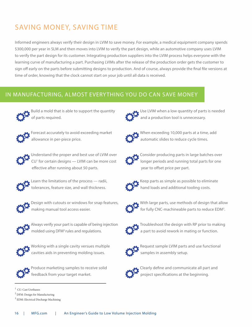
SAVING MONEY, SAVING TIME
Informed engineers always verify their design in LVIM to save money. For example, a medical equipment company spends
$300,000 per year in SLM and then moves into LVIM to verify the part design, while an automotive company uses LVIM
to verify the part design for its customer. Integrating production suppliers into the LVIM process helps everyone with the
learning curve of manufacturing a part. Purchasing LVIMs after the release of the production order gets the customer to
sign off early on the parts before submitting designs to production. And of course, always provide the final file versions at
time of order, knowing that the clock cannot start on your job until all data is received.
IN MANUFACTURING, ALMOST EVERYTHING YOU DO CAN SAVE MONEY
Build a mold that is able to support the quantity
of parts required.
Forecast accurately to avoid exceeding market
allowance in per-piece price.
Learn the limitations of the process — radii,
tolerances, feature size, and wall thickness.
Design with cutouts or windows for snap features,
making manual tool access easier.
Always verify your part is capable of being injection
molded using DFM2 rules and regulations.
With large parts, use methods of design that allow
for fully CNC-machineable parts to reduce EDM3.
Troubleshoot the design with RP prior to making
a part to avoid rework in mating or function.
Working with a single cavity versues multiple
cavities aids in preventing molding issues.
Produce marketing samples to receive solid
feedback from your target market.
Clearly define and communicate all part and
project specifications at the beginning.
Request sample LVIM parts and use functional
samples in assembly setup.
Keep parts as simple as possible to eliminate
hand loads and additional tooling costs.
Understand the proper and best use of LVIM over
CU1 for certain designs — LVIM can be more cost
xxxeffective after running about 50 parts.
Consider producing parts in large batches over
longer periods and running total parts for one
xxxyear to offset price per part.
When exceeding 10,000 parts at a time, add
automatic slides to reduce cycle times.
Use LVIM when a low quantity of parts is needed
and a production tool is unnecessary.
1 CU: Cast Urethanes2 DFM: Design for Manufacturing3 EDM: Electrical Discharge Machining
16 | MFG.com | An Engineer’s Guide to Low Volume Injection Molding

Save time and moneyby using MFG.com’s
Supplier Discovery tool
Log in and start sourcing today!
THE CLOCK ON YOUR JOB CAN’T START UNTIL ALL DATA IS RECEIVED
From sending the wrong revision to hoping that non-conducive geometries might somehow work, many tools are built
in error, wasting money. Parts with particularly thick sections undergo significant shrinkage defects to the entire diameter
of the part, causing failure. Expensive tooling changes and engineering change orders (ECOs) are often required to
compensate for part design issues.
Design decisions can also waste capital. Avoid designing parts that
have side actions, and watch out for designs that need multiple
threaded inserts — Additional costs hide in parts designed with
many side actions. With these parts, customers often expect a
much lower price than what they actually get.
Wrong expectations are the biggest waster of time and money.
Don’t expect that a tool with multiple actions or inserts can be
made on a short LVIM timeline when its manufacture truly requires
a 12-week schedule.
Remember: It’s very expensive to change a mold requiring the addition
of material in order to create a new feature. But if you follow the steps
and advice found in this book, you will no doubt save time, money,
and get your products to market faster.
“One automotive company tried to switch from PC to acrylic after
tool completion and was unable to produce acceptable parts. With
orders for both materials already sold, they were
faced with providing product made of only
one material.
17 | MFG.com | An Engineer’s Guide to Low Volume Injection Molding