Engineering Project Proposal - University of Michigan
57
Engineering Project Proposal A Desktop Reactor for Plasma Enhanced Growth of Carbon Nanotubes Team 23 Kyler Nicholson John Taphouse Janani Viswanathan Bryan Yamasaki Sponsors Professor John Hart Dr. Michael Fl De Volder Eric Meshot University of Michigan, Department of Mechanical Engineering Section Instructor Professor John Hart December 9, 2008
Transcript of Engineering Project Proposal - University of Michigan

Engineering Project Proposal
A Desktop Reactor for Plasma Enhanced Growth of Carbon Nanotubes
Team 23
Kyler Nicholson
John Taphouse
Janani Viswanathan
Bryan Yamasaki
Sponsors
Professor John Hart
Dr. Michael Fl De Volder
Eric Meshot
University of Michigan, Department of Mechanical Engineering
Section Instructor
Professor John Hart
December 9, 2008
2
1.0 Executive Summary
There are many potential applications for vertically aligned carbon nanotubes (CNTs), including
various microelectronic and micromechanical devices. Vertically aligned CNTs, especially
single isolated CNTs, cannot be consistently grown using pure thermal chemical vapor
deposition (CVD) system. However, recent research suggests that the addition of plasma to CVD
systems can greatly enhance the probability of growing vertical CNTs. Working with Professor
John Hart, Dr. Michael Fl De Volder, and Eric Meshot of the Mechanosynthesis Laboratory, our
team is to design and build a desktop sized plasma enhanced chemical vapor deposition
(PECVD) system.
To achieve this goal our team systematically identified customer requirements and quantitative
engineering specifications. The customer requirements and engineering specifications were
analyzed using a quality function deployment (QFD) diagram, which identified three key
customer requirements:
Control of Operating Conditions: provides control over temperature, pressure, plasma, and
flow rate
Adjustable Electrode Gap: provides variability in electric field conditions
System Size: system should be able to fit on a desktop
Background research and system level benchmarking revealed that PECVD systems can
generally be broken down into 3 modules and one submodule of design: reaction chamber,
plasma coil and electronics, operating condition controllers, and the substrate holding and
heating assembly respectively. The customer requirements and specifications were used to guide
the formation of preliminary design concepts for each module.
The final system design fits on an 18 by 18 inch base plate and is no more than 12 inches tall.
The reaction chamber is composed of three mutually orthogonal tubes intersecting at their
midpoint. Attached to the end of one of the tubes is a quartz tube. The plasma coil will be
wrapped around the quartz tube and ignite the reactant gases before entering the reaction
chamber. The entire substrate holding and heating mechanisms and the adjustable electrode are
packaged onto a single tray that can be easily slide in and out of the reaction chamber. The
chamber and infrared sensor are conveniently packaged on a stand with a linear bearing for
opening and closing the chamber. A complete schematic can be seen in Figure 16.
The entire chamber will be composed of prefabricated commercially available components. The
only system components that will require machining are the system tray, electrode, substrate
holding heat sinks, and system stand. The system tray and substrate holding heat sinks will be
machined professionally due to their intricate geometry. The electrode and system stand will
machined by the project team using waterjet cutting techniques. Once, all manufacturing is
complete the project team will assemble the entire system by hand.

3
2.0 Table of Contents
1.0 Executive Summary ................................................................................................................................ 2
2.0 Table of Contents .................................................................................................................................... 3
3.0 Background ............................................................................................................................................. 6
4.0 Customer Requirements and Engineering Specifications ....................................................................... 7
5.0 Modules and Strategies of Design .......................................................................................................... 8
5.1 Design Modules .................................................................................................................................. 9
5.2 Strategies ............................................................................................................................................. 9
6.0 Brainstorming and Concept Generation ................................................................................................ 10
7.0 Concept Summary ................................................................................................................................. 10
7.1 System Concepts ............................................................................................................................... 10
7.2 Key Submodules ............................................................................................................................... 14
7.2.1 Adjustable Electrode .................................................................................................................. 14
7.2.2 Internal Chamber Assembly ....................................................................................................... 15
8.0 Concept Screening and Selection .......................................................................................................... 15
8.1 Concept Screening ............................................................................................................................ 15
8.2 Observations and Discussions ........................................................................................................... 16
8.3 Final Concept .................................................................................................................................... 16
9.0 Final Design .......................................................................................................................................... 17
9.1Chamber Design ................................................................................................................................. 18
9.2 Internal Chamber Assembly.............................................................................................................. 19
9.3 Base and Supports ............................................................................................................................. 20
9.4 Electronic Design and Set-up ............................................................................................................ 22
9.5 Bill of Material .................................................................................................................................. 23

4
9.6 Engineering Design Parameter Analysis ........................................................................................... 24
9.6.1 Parameter Analysis Examples ................................................................................................... 24
9.6.2 Material Selection ...................................................................................................................... 28
9.7 Failure and Safety Analysis .............................................................................................................. 28
9.8 Environmental Analysis .................................................................................................................... 30
10.0. Manufacturing and Assembly Plan .................................................................................................... 32
10.1 Outsourced Components ................................................................................................................. 32
10.2 Waterjet machined parts.................................................................................................................. 33
10.3 Purchased Components ................................................................................................................... 34
10.3.1 Chamber Components .............................................................................................................. 34
10.3.2 Stand Components.................................................................................................................... 35
10.3.3 Miscellaneous Components ...................................................................................................... 36
10.4 Assembly......................................................................................................................................... 36
10.4.1 Chamber Assembly ................................................................................................................... 36
10.4.2 System Tray Assembly .............................................................................................................. 37
10.4.3 System Tray Stand .................................................................................................................... 37
10.4.4 Miscellaneous Components ...................................................................................................... 37
11.0 Usability Analysis ............................................................................................................................... 37
12.0 Validation Plan .................................................................................................................................... 38
13.0 Risks and Countermeasures ................................................................................................................ 38

5
6
3.0 Background
The University of Michigan’s Mechanosynthesis laboratory under the direction of Professor John
Hart and Dr. Michael Fl De Volder, is dedicated to the development of processes for fabricating
carbon nanotubes (CNTs). CNTs show immense prospect in applications across many industries,
including microelectronics and advanced composites. For many of these applications the growth
of isolated vertical CNTs is required. Chemical vapor deposition (CVD) processes are currently
commonplace for growing CNTs. CVD is capable of growing dense forests of tall CNTs, like
those seen in Appendix A., but are unable to produce isolated vertical CNTs. Recent research
suggests that the addition of plasma to the CVD process can greatly enhance the probability of
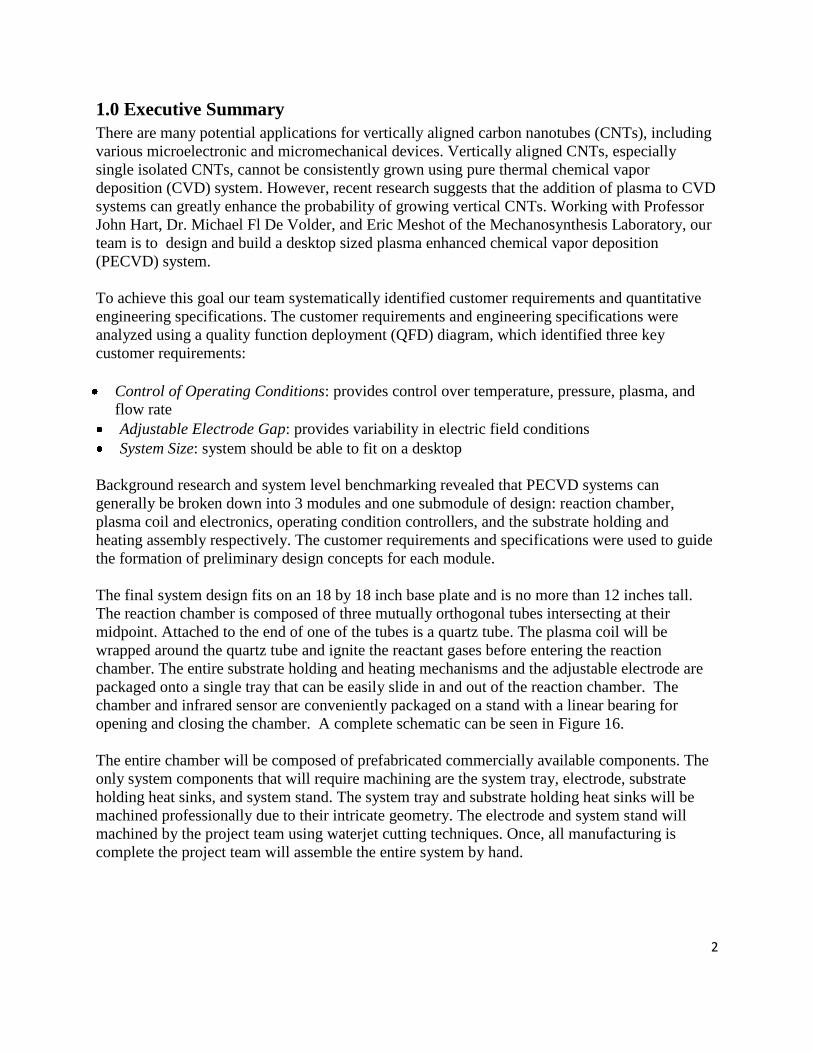
growing vertical CNTs. The addition of plasma provides three main benefits as shown in Fig 1
below. It aids in the decomposition of the reactant gases for producing the nanotubes, creates an
electric field that aligns the CNTs vertically, and adds energy to the reaction.
Fig. 1: Three benefits of plasma to a chemical vapor deposition system
Due to the Mechanosynthesis group’s lack of experience in plasma generation and processing we
were asked to develop a prototype plasma-enhanced chemical vapor deposition (PECVD)
system. Upon completion of the prototype, we have also been asked to confirm its ability to
fabricate vertically aligned carbon nanotubes and to display electron microscope images of the
CNTs grown using this technique at the design expo.
Background research was conducted and it revealed that there are four primary methods for
generating plasma in PECVD systems: Direct current (DC), RF triode, inductively coupled, and
microwave. The benchmarked designs for each of these methods can be seen in Figs. 2-5 below.

7
Figure 2: DC Powered PECVD
Figure 3: RF Triode Powered PECVD
Figure 4: Inductively Coupled PECVD Figure 5: Microwave Powered PECVD
A comparison of the operating parameters for each method can be seen in Appendix C. The
research also showed results for improved vertical alignment for all three of the plasma
generation methods. Finally, two strategies were identified for the PECVD design based on the
background research and benchmarked designs: local and remote. Details for this are covered in
section 5.2 of the report. All of the information sources used for the background research are
listed in references.
4.0 Customer Requirements and Engineering Specifications
The design of the system was guided by customer requirements and engineering specifications.
The customer requirements were gathered through meetings with the sponsors and can be seen in
Appendix B. To better guide the design the relative importance of each customer requirement
was determined through a pairwise comparison, as seen in Appendix D. The customer
requirements were then translated to quantitative engineering specifications through
benchmarking of existing PECVD designs and consultation with the project sponsors.
Additionally, the customer requirements and engineering specifications were analyzed using a

8
quality function deployment (QFD), Appendix E. The QFD identified key aspects of the design,
as well as the strength of correlation between each requirement and specification. The most
important design aspects as identified by the QFD are:
Control of Operating conditions: provides control over temperature, pressure, plasma, and
flow rate
Adjustable Electrode Gap: provides variability in electric field conditions
System Size: system should be able to fit on a desktop
5.0 Modules and Strategies of Design
Background research and benchmarking revealed that PECVD systems can be broken down into
three basic modules of design and one submodule: the reaction chamber, the plasma coil and
supporting electronics, the chamber operating condition controllers, and the internal chamber
assembly respectively. The reaction chamber is the central module, within which is the sub
module internal chamber assembly. The plasma electronics and operating condition controllers
are external modules that support the function of reaction chamber module, as seen in Figure 6
below. Our research also revealed that PECVD systems are generally designed along either
remote or local plasma strategies.
Figure 6: The reaction chamber is the central design module, within which is the
internal chamber assembly submodule. The plasma coil and electronics and
operating condition controllers support the function of the reaction chamber.
Plasma coil and
Electronics
Chamber
Operating
Condition
Controllers
Reaction Chamber
Internal
Chamber
Assembly

9
5.1 Design Modules
The reaction chamber is the central component of all PECVD systems and one of the most effort
intensive design modules. It is the chamber in which the plasma is generated and the entire
nanotube growth process takes place. It includes the chamber walls, viewports, reactant gas inlet
and outlet, as well as electrical feed through. All of the remaining design modules and
submodule are largely dependent on the design of the reaction chamber. The plasma coil and
supporting electronics and the operating condition controllers are particular to the method of
plasma generation, which is the dominant influence in the design of the reaction chamber.
Additionally, the internal chamber assembly submodule is largely dependent on the interior
geometry of the reaction chamber. For these reasons concepts were first generated for the
reaction chamber.
After a concept was selected for the reaction chamber design, development efforts were focused
on the design of the remaining modules and submodule. The design of the plasma coil and
supporting electronics involves design of the coil and selection of a power supply and matching
network. The design of the operating condition controllers involves selection of a pumping
system, fittings, and an infrared sensor. The design of both of these modules is largely inherent
to the chosen plasma generation method and reaction chamber design. The internal chamber
assembly submodule entails the design of the entire interior of the chamber, including, the
electrode, substrate holding mechanism, and resistive heating element. For this submodule a
preliminary concept was generated, as seen in Appendix F, and then iterated until a final design
was reached. During the design of the internal chamber assembly the electrode assembly was
identified as a design submodule required additional design work.
5.2 Strategies
Based on background research and benchmarked designs we identified two sensible strategies for
PECVD design: local and remote. In local plasma PECVD systems the plasma is produced
directly over the substrate in the growing environment. On the other hand, in remote plasma
PECVD systems the plasma is formed away from of the growing environment and then
channeled to the substrate. Each strategy has its associated advantages and disadvantages shown
in Table 1 below.
Table 1: Side by side comparison of remote and local plasma strategies
Remote Plasma Local Plasma
Advantages
No sputtering over substrate. Electric field over substrate.
Separate control of plasma and
electric field.
Disadvantages Weak electric field over
substrate.
Sputtering can damage
substrate or nanotubes.
The main disadvantage of the remote plasma strategy, a weak electric field for vertical alignment
of the nanotubes can be surmounted by introducing an independently created electric field

10
around the substrate. For this reason, the majority of our preliminary design concepts use the
strategy of remote plasma generation.
6.0 Brainstorming and Concept Generation
To generate our preliminary concepts each team member independently sketched two designs.
The designs were then reviewed and a discussion took place to improve and build upon the
designs. The revised designs were then presented to Dr. Michael De Volder who evaluated them.
Dr. De Volder helped to revise the existing concepts and through discussions several entirely
new concepts were developed. In total seven concepts were created and can be seen in section 7.
7.0 Concept Summary
In total, seven concepts were generated and can be seen below in Figures 7-13. Two concepts
were generated for each type of chamber geometry: a box, tube or cross and one “wild idea”. The
concepts utilized both local and remote plasma strategies. Chamber materials were also given
some consideration, as either stainless steel or quartz.
One key module of our design is the adjustable electrode. Two concepts for achieving an
adjustable electrode are shown in section 7.2.
7.1 System Concepts
Shown below are the seven concepts we developed for the system.
Figure 7: Box with local inductive plasma
11
The box with local plasma system uses an antenna wrapped in the shape of a stove heating coil.
This coil is placed outside the chamber on a quartz window to excite the plasma gas locally. The
front is opened like a clam shell to increase the access to the substrate.
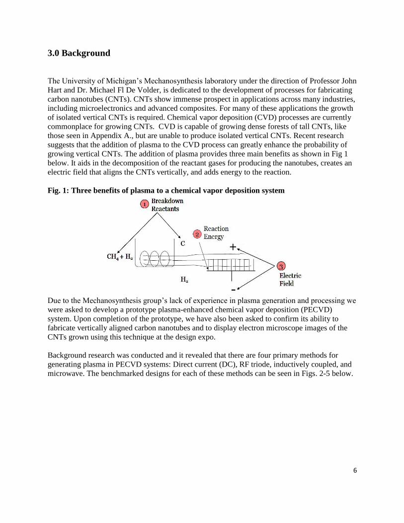
Figure 8: Box with remote inductive plasma and DC substrate bias
The box with remote inductive plasma creates remote plasma in the tube which moves
through the chamber. The remote plasma allows for disjoining the plasma source and
electric field. The user would open the end of the box where the gas outlet is to access the
substrate.
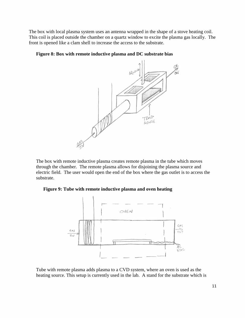
Figure 9: Tube with remote inductive plasma and oven heating
Tube with remote plasma adds plasma to a CVD system, where an oven is used as the
heating source. This setup is currently used in the lab. A stand for the substrate which is

12
electrically biased and a coil wrapped around the inlet of the tube would be the major
additions to the current setup.
Figure 10: Tube with remote inductive plasma and DC substrate bias
This tube design uses a single quartz tube, where plasma is generated in one end using a coil.
The electrodes are attached to a cap on the opposite end where a voltage can be applied. This
is a modification of a design currently used in the Mechanosynthesis Lab.
Figure 11: Pyrex cross with remote inductive plasma and DC substrate bias

13
The Pyrex cross design is made from commercially available Pyrex cross. One arm is used to
generate the plasma, while the other for loading the sample. This design has been used in many
research labs.
Figure 12: Pyrex or steel six-way cross with remote inductive plasma and DC substrate
bias
The six-way cross design can be made in a couple different ways. Three holes are machined in a
block of stainless steel, or three Pyrex tubes are attached in a cross fashion, or a stainless steel
chamber can be purchased from a vacuum system supplier. The extra arms can be used for
viewports, as well as having more adjustability later for different configurations.
Figure 13: Spherical Pyrex and steel chamber with local plasma source

14
The sphere is our “wild idea,” which uses a hemisphere of Pyrex to allow the viewing of the substrate
during nanotube growth.
7.2 Key Submodules
Preliminary concepts were also generated for two key submodules: adjustable electrode and
internal chamber assembly.
7.2.1 Adjustable Electrode
One key module that was determined for the system is the adjustable electrode. Below, two of
our preliminary concepts are shown to achieve an adjustable electrode.
Figure 14: Automatic Height Adjustment Concept
The automatic height adjustment concept uses a DC motor to rotate a wheel that raises or lowers
the electrode. A difficulty of this design is that the seal needs to be dynamic to allow the rod to
move and still keep the pressure difference between the chamber and atmosphere.

15
Figure 15: Manual Height Adjustment Concept
The manual height adjustment uses a threaded rod on which the electrode is attached and by
rotating the rod the electrode will move up or down. A cap with an o-ring is secured over the rod
which seals off the chamber from atmosphere.
7.2.2 Internal Chamber Assembly
The internal chamber assembly was identified as a key submodule of design. A preliminary
concept was generated for this module and is shown in Appendix F. The concept was then
reviewed and refined through discussion with the sponsors until a final design was achieved.
8.0 Concept Screening and Selection
This section will go into detail on how we developed and utilized a screening process to
determine our top two system concepts. We observed how current systems are used in the lab as
well as talked to current users of CVD systems, to help us pick a winning concept. We have also
made refinements to this concept since DR2 to make it a more practical design.
8.1 Concept Screening
To evaluate our seven system design concepts, we decided to rate them against five of our
critical criteria to determine the top two choices. The five criteria we used are: Cost, Ease of
Fabrication, Adjustability, Size and Access to Substrate. The cost is a concern, to keep the
project budget at a reasonable level for a one-off PECVD system. The ease of fabrication is

16
important, because we need to be able to make and assemble the system, and if that is not
possible, then the customer requirements cannot be met. The adjustability of the system helps to
increase the number of ways the system can be used, thus decreasing the cost of ownership to the
customer. The size is important, because the desktop size is a major customer requirement. The
access to the substrate is needed, to let the user easily swap out samples and to reduce time
between experiments.
Each design concept was rated a zero, one or two for each criteria; zero meaning bad, one is fair
and two is good. This methodical process helped us think deeply about each design and
determine the strengths and weaknesses. After rating each concept and totaling up the score the
top two design concepts were: Box with remote plasma and steel six-way cross. Below, Table 2
shows the complete comparisons of our design concepts.
Table 2: Box with remote plasma and the steel tri-cross are the leading design
candidates
Box
(Local
plasma)
Box
(Remote
plasma)
Tube
(Oven
heating)
Tube
(Local
heating)
Cross
(Pyrex)
6-way
Cross
(steel)
Sphere
Cost 2 2 2 2 1 2 0
Ease of Fabrication 1 1 1 2 1 1 0
Adjustability 0 2 0 0 1 2 0
Size 1 1 1 2 1 1 2
Access to Substrate 2 2 1 0 0 1 2
0 – Bad, 1 – Fair, 2 - Good 6 8 5 6 4 7 4
8.2 Observations and Discussions
To help decide between the two leading design concepts, we discussed with lab users Dr. De
Volder and Eric Meshot. They both have used a variety of CVD setups and know what features
are helpful to increase the usability of a system. We also watched Dr. de Volder setup and begin
growing CNTs, which helped us see how users handle samples.
To help decide between local and remote plasma we met with Professors Foster and Kushner,
who both do research involving plasmas. They helped us establish the benefits of local and
remote plasma sources and provided consultation for choosing a plasma generation method.
8.3 Final Concept
Consultations with Professor Foster and Professor Kushner were instrumental in deciding to use
a remote inductively coupled plasma source. Having a remote plasma source will allow
decoupling of the plasma and electric field control, providing increased adjustability to the

17
system. The inductively coupled plasma source comes at a lower cost than microwave plasma
and operates more cleanly than a DC plasma source.
Throughout our observations and discussions with Dr. De Volder and Eric Meshot, we
determined that any benefit of having a box shape, which would have a better access to the
substrate, were out weighted by the difficulty we would have to close up and seal the chamber
for vacuum. We also determined that having six arms in a cross would allow for greater
adjustment in the future. For these reasons we chose to go forward with the six-way cross.
Due to the short time frame of this project, we decided to purchase parts for the chamber from
vacuum component companies. This ensures that all of our fittings will hold vacuum, will be
easy to assemble and will decrease the amount of time we need to spend machining parts.
The decision to use inductively coupled plasma required that a quartz tube be attached onto the
end of the gas inlet arm of the cross for plasma generation. The conductive properties of stainless
steel would create an issue if we were to wrap a coil around it and try to ignite plasma. The use
of a quartz tube to generate plasma in is also beneficial, so that the plasma can be seen and
monitored easily.
9.0 Final Design
The complete system can be seen below in Figure 16. We broke up the final design into three
main subassemblies. The first subassembly is the reaction chamber (Figure 17). This includes the
reaction chamber body and the quartz tube in which the plasma is generated. The second is the
internal chamber assembly (Figure 18). This includes all the substrate holding and heating
mechanisms and the electrode. The final subassembly is that of the base and supports (Figure
20). This includes all chamber supports, IR sensor and support, internal system tray support, and
the base to which all supports will be attached.

18
Figure 16: Final system design, composed of three subassemblies
9.1Chamber Design
For the design of the chamber, we chose a 2 inch diameter six-way cross geometry (purchased
from Lesker), due to its versatility and wide selection of standards components. All flanges meet
the standards for Klein Flanges (KF) by the International Standards Organization and can
therefore be connected together with ease. The gas flow will enter through a Swagelok fitting as
seen on the left side of Figure 17. The flow of gas will then travel through a 1 inch diameter
quartz tube. This tube will be attached to the system with two quick connect fittings, facilitating
the ease of interchangeability to new clean tubes and tubes of different length. A copper wire
will be wrapped around this tube and connected to the RF generator for creating the plasma. A
second quick connect will be used for attaching the quartz tube to the left side of the six-way
chamber. The top and back flange of the chamber will have kodial glass viewports for viewing of
internal components, while the bottom flange will have a kodial glass viewport for optical access
for an IR sensor. The front flange will be for the electrical feedthrough, which consists of eight
individual pressure sealed copper pins. The gas will then flow out through a standard KF flange
connected to a steel hose, which is in turn connected to a vacuum pump.

19
Figure 17: Chamber design subassembly
9.2 Internal Chamber Assembly
The internal chamber assembly, seen below in Figure 18, is for providing support to all the
components used for the growth of the carbon nanotubes. The backbone of this subassembly is
the system tray, which is fixed to the electrical feedthrough flange using steel dowel pins and set
screw collars. The dowel pins with be press fit through the flange and slip fit through the system
tray. The bottom three electrical feedthrough pins will be clipped off to avoid interference with
the system tray.
Sitting inside two grooves in the system tray are two quartz rods. The function of the rods is to
support the substrate assembly and to keep it electrically isolated from the system tray and
chamber. The substrate assembly consists of two heat sinks and a silicone resistive heating
element, which will support the substrate. The function of the heat sinks is to hold the silicone
heating element and to pass current through it, which will in turn heat up the substrate. A closer
look at the heat sink construction can be seen in Figure 14 below. The silicone heating element
sits directly on the heat sink; a small blank plate sits on top of that. The top plate has two through
holes and one threaded hole. The two through holes are to screw the top plate to the heat sink
while the middle threaded hole is to screw a thumb screw into the middle plate. The added
pressure of the thumb screw on the middle plate ensures a large contact area of even pressure on
the silicone heating element.
An electrode will be used to create an electric field and will be supported by two quartz rods set
into the system tray vertically. The height will be controlled by a set of silver tipped set screws.
One of the electrical feed through pins will be connected to this electrode. Each heat sink will
also be connected to feed through pins as well. The last two pins are to be used for a removable
thermocouple to calibrate the IR sensor. The actual connection wires and clamps are to be
determined.

20
Figure 18: Internal Subassembly
Figure 19: Exploded view of heat sink construction
9.3 Base and Supports
The purpose of this subassembly is to support the chamber, the IR sensor, and the system tray.
The base plate will composed of a flat piece of aluminum. The chamber supports will be
mounted to this plate. These supports will keep the chamber at a fixed height. The IR sensor
stand will also be screwed to the base plate. The IR sensor stand allows for vertical adjustment of

21
the sensor to properly calibrate it to the appropriate height. The system tray holder will keep the
internal subassembly with the system tray at a controlled height. This holder allows for vertical
motion to adjust the stand to align properly with the chamber. The holder will also slide on a rail
to be able to pull the system tray completely out to of the chamber, as seen in Figure 20 below.
This is beneficial for loading and unloading substrates for the growth of carbon nanotubes,
replacing silicon heating elements, and removing of entire system tray for cleaning. The holder
will be connected to the internal subassembly through a plate that clamps onto the push fit
dowels in the electrical feedthrough flange as mentioned in the previous subsection.
Figure 20: Base and supports

22
Figure 21: View of internal subassembly completely removed from chamber by
sliding on rail
9.4 Electronic Design and Set-up
Fig. 22 below shows the electrical connections for the reactor system. The inductive coil
wrapped around the quartz tube is connected in parallel to the shunt capacitor in the matching
network. The matching network is in turn connected to the RF power generator and an automatic
matching network controller. The automatic matching network tunes/ matches at any given time
the impedance of the load (plasma) to that of the source (generator). It has to be ensured that the
coil and the matching network have adequate housing with ground connections in them, to
reduce the risk of being electrocuted. The entire setup of the tube and the coil is wrapped around
by a copper mesh which acts as a faraday’s cage to reduce the interference of the RF from any
other surrounding equipment and the generator itself.

23
Figure 22: Representation of the Electrical set-up for the reactor system
9.5 Bill of Material
Appendix G provides a summarized table listing the part numbers and descriptions, vendors, list
prices and lead times for all system components. Of our parts, the weldable flange and
feedthrough is the only custom part and has a reasonably short lead time of one week. One of
the most expensive parts is the RF generator and the matching network, costing $5000. The RF
generator and the matching network is a refurbished model capable of 500W. Its price is
competitive with the price of a new generator rated for 300W without a matching network. While
only 300W was determined necessary from the parameter analysis, 500W gives us flexibility in
operating the generator over a wide range of power. The matching network is necessary for the
system because it transforms the steady state impedance of the load (plasma) back to an
impedance which is optimum for the RF generator (50 Ω) and protects (buffers) the RF generator
from unstable load conditions. If the load is not perfectly matched, then some of the power is
reflected back to the generator. The most expensive part of the system is the vacuum pumps,
costing approximately $7,000. In order to meet the customer specifications for flow rates and
the low vacuum pressure, two pumps were required. However, for the purposes of our project,
we decided to use the pump provided to us by our sponsors. This will run at a pressure of 0.6
torr, instead of the 0.1 torr that new pumps would have provided. This will affect the plasma
Matching Network
RF Generator
Matching Network
Controller
COIL/
Load
Chamber
Outlet to
Pump

24
generation process and the growth process in turn, but for the purposes of our project this was
deemed as an effective solution for the testing stage and considerably lowers the cost.
Finally, 6061 aluminum was chosen to manufacture the base plate and the support for the
chamber. Two aluminum plates measuring 18” by 18” will be required to machine these parts.
9.6 Engineering Design Parameter Analysis
Plasma modeling was carried out, with the help of Professor Mark Kushner in the EECS
department, to determine the effect of input parameters (inputs) such as power and pressure.
Based on the results, the power to be supplied, the current through the inductive coil and the
chamber pressure was determined. The modeling also provided a check to ensure that the
maximum temperatures reached by the quartz tube and the chamber did not exceed the maximum
service temperatures of the materials. By inputting different dimensions of the chamber and the
quartz tube, the modeling enabled us to view the effect of changing geometries, and thus allowed
us to choose dimensions which produced reasonable results. Additionally, calculations using the
through-put formula were performed with the specified flow rate and pressure. This enabled us
to determine the pump type and specifications such as the pump speed. The sections below
describe in further details the analysis carried out for the power selection, the pump capacity, and
the chamber dimensions.
9.6.1 Parameter Analysis Examples
Power selection
The modeling was carried out for argon gas for two primary test cases: 50 W and 300 W at a
pressure of 0.1 torr and 100 sccm. The electron density, the temperature of the reactant gas
(argon) and the total power deposited to all the excited states of the gas and the electrons (load)
was considered at these powers. The figures below show that the electron density, the
temperature, and the total power deposited to the load were higher for the 300W simulation than
the 50 W simulation. At 300 W, the temperature of the argon gas in its neutral and excited states
averaged at 70°C, which was well within the maximum service temperature range of 1100 –
1400°C for the quartz tube and 250 – 300°C for the O-ring connecting the tube to the chamber.
The temperature of the neutral gas species was calculated by imposing a constant temperature
boundary condition of 52°C on the quartz tube wall. Once the temperature of the neutral gas was
determined, it can then be safely assumed as the wall temperature in the absence of any active
insulation i.e. a temperature gradient now exists between the wall and air, instead of the neutral
gas and wall (Refer to Appendix H for temperature plots for argon in its neutral and excited
states). Moreover, it can be seen from Figure 23a that the electron density extends into most of
the inner chamber without the aid of the gas flow due to the pump and thus the substrate is
continually exposed to the plasma during the process. We also noticed from the modeling that
the total power deposited to the load was approximately 80 W/cm3. This means that over the 2
cm length of the tube shown in Fig. 23b, the total power deposited to the plasma load can be
determined as,
2
3
1240
2TOT
WP P dVolume P r h W
cm
(Eq. 1)

25
This is close to the source power of 300 W and provides a check for the above results, validating
the accuracy for the set of conditions imposed (pressure, temperature, chamber and coil
dimensions and flow rates). This consequently also enabled us to determine the maximum
current that could flow through the inductive coil to be approximately 10 A.
Figure 23: Contours plots depicting a) electron density and b) total power deposited
to plasma at 300W
a. b.
Figure 24: Contours plots depicting a) electron density and b) total power deposited
to plasma at 50W
a. b.
As can be seen from Figure 24 above, at 50 W, both the neutral gas (and wall) tempertaure and
the electron density are lower than 300 W. However, the electrons penetrate almost the same

26
distance into the tube as with 300 W and thus the substrate is still desirably exposed to the
plasma even when there is no flow. Using a similar calculation as Eqn. 1 above, we can
determine that the total power transferred to the plasma is around 40 W, given a power
deposition of 20 W/cm3. Since this equation is just an approximation, 40 W is considered close
enough to the source power of 50 W.
It can thus be concluded that for a power range between 50 – 300 W, the substrate will lie in the
plasma range and thus be exposed to the plasma continually during the reaction process.
It is stressed however that the above modeling procedure was carried out for argon gas since it is
the easiest to model. The actual system uses methane and hydrogen for the reactant gases which
have an increased number of excited states, ions, electrons and thus reaction mechanisms,
increasing the complexity considerably.
Furthermore, the modeling has been carried out for a 4mm diameter inductive coil with 4
windings along the tube. Since it is likely that the coil incorporated in the final design would
actually be a commercially available ⅛ inch (6mm) coil, the above results for the temperaure
ranges will vary, with an increased probability of the system experiencing higher temperatures
than stated.
Modeling analysis was carried out for the same conditions but with different coil diameter of
approximately 6mm and 50 W power supply. The plotted results are shown in Appendix I. The
average wall temperature at 50 W is estimated at 50°C (323 K), and the total power deposited is
higher at 38 W/cm3. The electron denisty penetrates to the same extent into the chamber as with
the 4mm coils. Since modeling data is currently unavailable for 300 W, it is unclear on how
much the temperature varies with the 6 mm coils and thus no upper bounds on the temperature
have been determined yet.
The total increase in temperature is anticipated to be around 150 – 200 K. As a safety precaution,
fans will be positioned along the tube to cool the tube exterior and the components connected to
it, in case of a steep rise in temperature.
Vacuum Pump
An important item for the system is the vacuum pump, which creates favorable conditions to
generate plasma. The critical customer requirements for the pump are the throughput, at 100
standard cubic centimeters per minute (sccm) and the pressure, at 1 mTorr. Below the formula
for throughput is shown, which relates the throughput, pressure and pumping speed.
ThroughputPumping speed
Pressure (Eq. 2)
To try to reduce the cost of a pump, a secondary pressure of 5 mTorr was prescribed by the
customer. Below in Table 3, for a given throughput and pressure the required pumping speed is
shown.

27
Table 3: Calculation of Pumping Speed with Throughput and Pressure
Throughput (sccm) Pressure (mTorr) Pumping speed (L/s)
100 1 1267.817
100 5 253.75
Both of these pumping speeds require diffusion pumps. For a pressure of 1 mtorr the pump that
would be recommend would be a Varian VHS-6 and for a pressure of 5 mtorr the pump that
would be recommend would be a Varian VHS-4. A pumping speed curve for the VHS-6 is
shown below in Figure 25.
Figure 25: Pumping speed curve for Varian VHS-6
For all diffusion pumps, an example of which can be seen above, once the pump gets into its
working pressure range, the throughput is constant for pressures lower than the threshold
pressure. This can be useful for the system, because if the pressures needed for better plasma
generation, or carbon nanotube growth, are lower than 1 mTorr, these types of pumps can expand
the experimentation range.
A drawback to these pumps is that the price is higher than mechanical pumps. Another
drawback is these pumps need a backing pump to reduce the pressure to help the pump work
efficiently. This increases the cost of the pump, since you need to purchase two pumps to in
order to achieve optimum conditions.
Dimensions on quartz tube length
Since the placement of the coil was restricted to region near the center or not too close to the two
ends of the tube, different tube lengths needed to be modeled to verify their effect on the
plasma’s ability reach to the substrate. This is because the two ends of the tube consist of O-rings
which cannot withstand the high temperatures that they might experience of near the coil. For
simplicity, the chamber was modeled as a cylinder with the quartz tube connecting to it on one
end. Initially, modeling was carried out with a tube length of 30 cm. However, this proved to be
28
ineffective, with most of the plasma formed being concentrated at the end of the tube farthest
from the chamber. Thus the tube was made shorter and modeled at 15 cm. This seemed to
provide the appropriate length for the plasma which was now able to penetrate more than half of
the inner chamber as show in Fig 23 above. Conversely, the diameter of the tube was provided
by our sponsor as 2.5 cm. Since the quartz tube was connected to the chamber by means of an
O-ring, we believed that making the tube any shorter would be undesirable, as it would bring the
inductive coil closer to the chamber and potentially cause the O-ring experience a temperature
higher than its service temperature of 250 – 300°C.
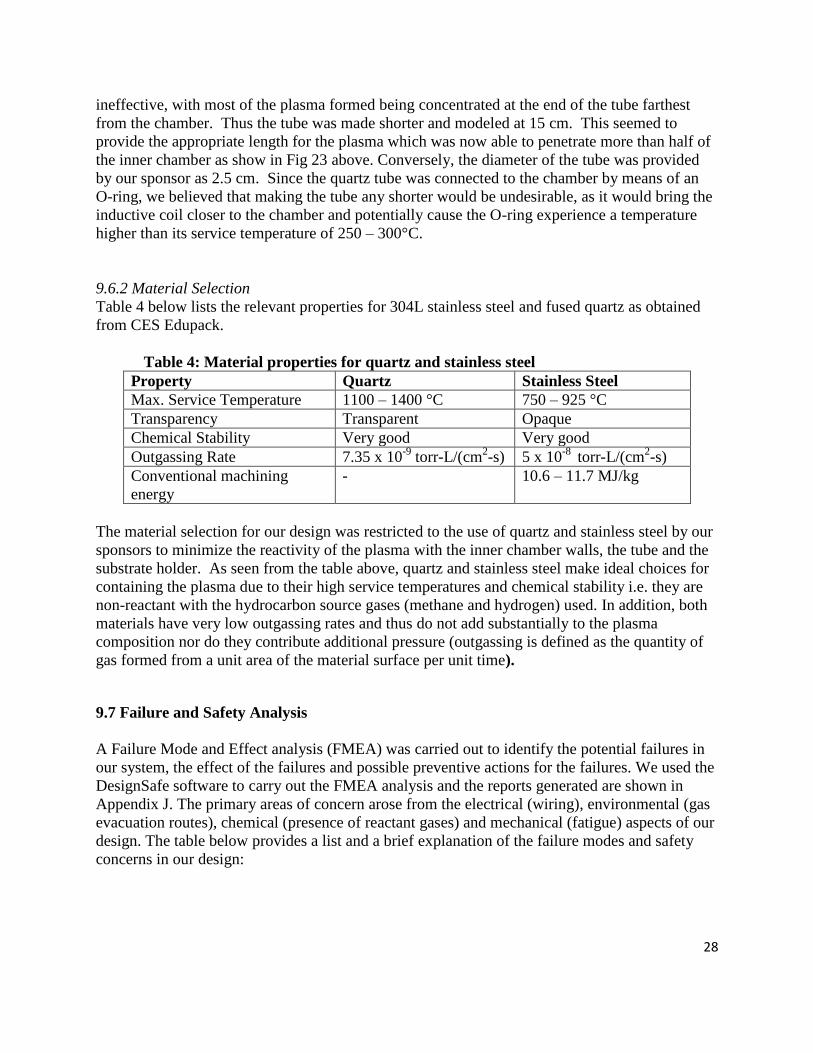
9.6.2 Material Selection
Table 4 below lists the relevant properties for 304L stainless steel and fused quartz as obtained
from CES Edupack.
Table 4: Material properties for quartz and stainless steel
Property Quartz Stainless Steel
Max. Service Temperature 1100 – 1400 °C 750 – 925 °C
Transparency Transparent Opaque
Chemical Stability Very good Very good
Outgassing Rate 7.35 x 10⁻⁹
torr-L/(cm2-s) 5 x 10
-8 torr-L/(cm
2-s)
Conventional machining
energy
- 10.6 – 11.7 MJ/kg
The material selection for our design was restricted to the use of quartz and stainless steel by our
sponsors to minimize the reactivity of the plasma with the inner chamber walls, the tube and the
substrate holder. As seen from the table above, quartz and stainless steel make ideal choices for
containing the plasma due to their high service temperatures and chemical stability i.e. they are
non-reactant with the hydrocarbon source gases (methane and hydrogen) used. In addition, both
materials have very low outgassing rates and thus do not add substantially to the plasma
composition nor do they contribute additional pressure (outgassing is defined as the quantity of
gas formed from a unit area of the material surface per unit time).
9.7 Failure and Safety Analysis
A Failure Mode and Effect analysis (FMEA) was carried out to identify the potential failures in
our system, the effect of the failures and possible preventive actions for the failures. We used the
DesignSafe software to carry out the FMEA analysis and the reports generated are shown in
Appendix J. The primary areas of concern arose from the electrical (wiring), environmental (gas
evacuation routes), chemical (presence of reactant gases) and mechanical (fatigue) aspects of our
design. The table below provides a list and a brief explanation of the failure modes and safety
concerns in our design:

29
Table 5: Failure mode identification and causes
Hazard
Category
Failure type/
Safety Concern
Cause of failure
Mechanical Failure in the
O-ring
The temperature in the quartz tube could exceed the
maximum service temperature of the O-ring, leading to failure
Fluid Pressure Vacuum Could be a possible failure cause since improper chamber
evacuation would negatively affect CNT growth.
Electrical Live parts A major safety concern since the inner chamber is equipped
with bare wires and a500 V DC bias between the electrodes
Lack of
grounding
A major safety concern since carelessness in grounding the
chamber could lead to electrocution
Arcing Undesirable, but arcing could occur between the substrate and
the electrode due to the 500V DC bias and the presence of
plasma, producing very high temperatures
Improper
Wiring
Could lead to an inefficient system, if not harm the user.
Improper wring could result from the electrodes not being
properly connected to the power supply or from the power
supply not being matched to the plasma load resistance.
Power supply
interruption
Not a major safety or failure issue, but a power break out
would require the process to start again, thus involving the
spending of more time and resources.
Coil windings
around quartz
tube
Could pose a risk of electrocution if touched accidentally, or
also provide a source of RF interference with other lab
equipment. Needs to be properly insulated with coil
insulation and a faraday’s cage.
Human factors Deviations
from safe work
practices
The primary concern in this area included failure to wear
gloves while handling the CNTs and perform standard safety
procedures while handling electrical circuits.
Fire and
explosions
Hot surfaces A safety concern involving the high temperatures of the tube
and the chamber, which might lead to burns or scalds.
Flammable gas Hydrogen is one of the reactant gases used in the process and
is also highly flammable. Thus, any leaks or the presence of
air in the system can pose a potential fire hazard.
Inadequate
egress
Evacuation
Routes
This was another safety concern, since any loose connection
or leaks in the evacuation routes for the reactant gases and the
plasma can raise serious environmental concerns.
Temperature Severe heat The formation of plasma releases a high amount of energy and
thus could lead to the system components failing faster due to
fatigue than their normal lifecycle.
Environmental
& Biological
Asphyxiants Overexposure to methane could be hazardous as it acts as an
asphyxiant and thus any leaks have to be taken care of as soon
as possible.
Chemical Reactions with
chemicals
This could lead to a possible failure mode and a serious safety
concern. If the chamber was accidentally opened during its
operation, since the process involves continual reaction

30
between the reactant gases and the substrate
Chemical
gases
Helium A safety concern, as acute or chronic respiratory conditions
may be aggravated from overexposure to this gas. Thus,
regular leak checks must be conducted.
Hydrogen As explained previously, hydrogen is a flammable gas and
poses a fire hazard
Methane As explained previously, methane acts as an asphyxiant and is
flammable thus posing the risk of a fire or an explosion, in
case of leaks.
Biological Eye contact A safety concern since in the case of leakage, methane causes
eye irritation
Skin Contact A safety concern since in the case of leakage, methane causes
skin irritation
Radiation High speed
electrons
Breakdown of reactant gases creates ions and electrons and
thus cause radiation in the tube. This can cause unwanted
interference with other equipment in lab.
As can be seen from the above table, most of the safety concerns arise from leaks in the tubing
connections and improper wiring in the electrical connections. These issues could not be
addressed directly in our design and thus we recommend double checking all tubing and
electrical connections and testing for leaks on a regular basis to prevent most of the above
concerns. Another major failure concern arose from the fact that the temperatures reached by the
system could not be accurately predicted by the modeling. It is anticipated that the system would
reach temperatures higher than those determined from modeling and this is a primary concern for
the O-rings connecting the quartz tube to the chamber and gas tubing. To address this issue, a
temporary solution of placing muffin fans along the length of the tube and the coil has been
decided. This is a relatively easy and inexpensive procedure and highly effective in reducing the
system temperature. However, as a long-term consideration, we would recommend the use of a
water jacket or a cooling fin that would cool the quartz tube and the coil.
FMEA analysis was performed for all of the above safety concerns, and failure modes and a risk
level report was developed, along with possible considerations for reducing the risk level for
each (refer to Appendix J).
9.8 Environmental Analysis
Simapro software was used to carry out our analysis for the environmental impact of our design.
Figure 26 below shows the plot for the total raw, air, water, waste and soil emissions for 2300g
of 304 L stainless steel and 200g of glass (this was used since it was the closest approximation to
quartz in the software). As can be seen Stainless steel has the maximum raw emission at
approximately 8000g followed by glass at 4000g. Other emissions are negligible when compared
to the total raw emission.

31
Figure 27 indicates the impact of stainless steel and quartz manufacturing to the mineral content,
land use, acidification, eco-toxicity, ozone layer, radiation, climate change, resp. inorganics and
organics, and finally carcinogens. As can be seen, stainless steel is the main contributor to most
of the impacts. However, to reduce this impact on the environment to this extent would require
using a different material for our chamber which presents a challenge, since stainless steel is
easily available, cheap and highly suited for non-reactive conditions and machinability. It also
has the potential to withstand plasma, which makes it in our case, highly desirable.
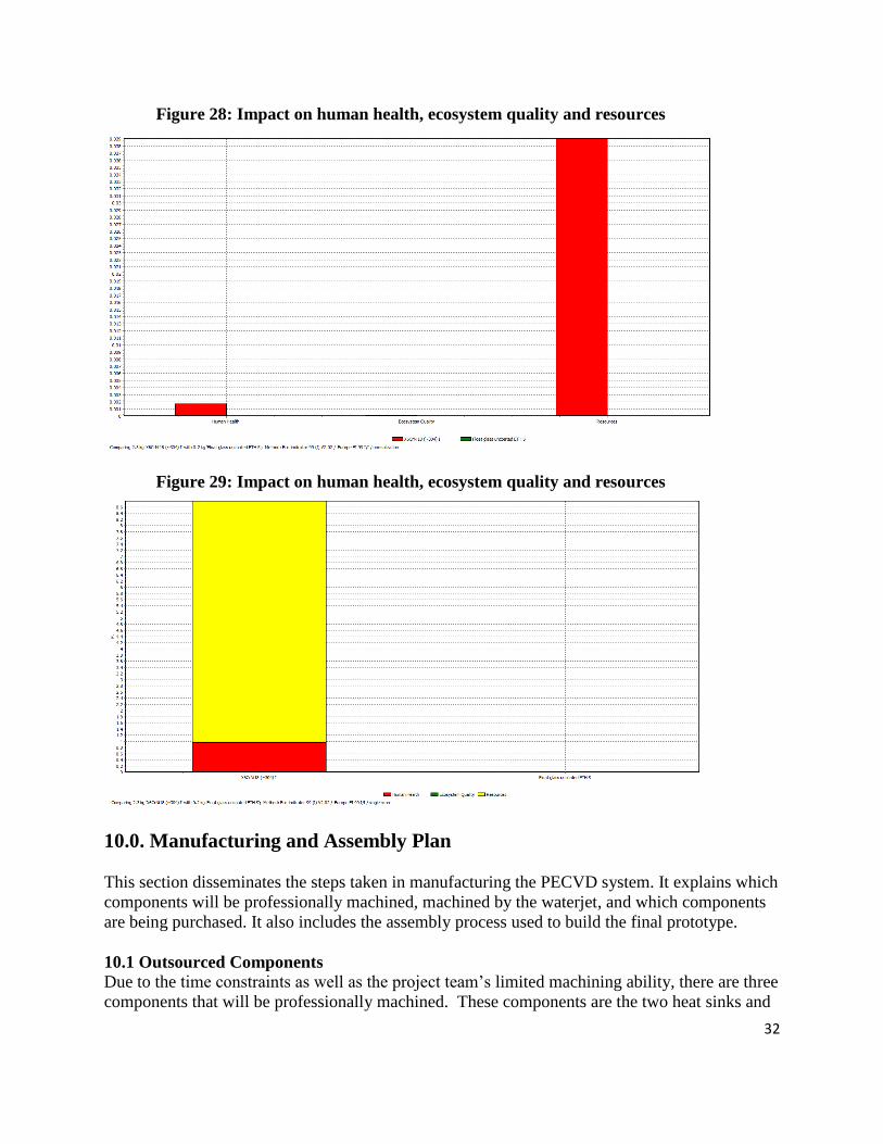
Finally, Figure 28 and 29 show that manufacturing stainless steel and quartz has a higher impact
on natural resources than on human health. This is in accordance with the raw emission figures
above for both quartz and stainless steel.
Figure 26: Total emissions for quartz and stainless steel
Figure 27: Impact of stainless steel and quartz
32
Figure 28: Impact on human health, ecosystem quality and resources
Figure 29: Impact on human health, ecosystem quality and resources
10.0. Manufacturing and Assembly Plan
This section disseminates the steps taken in manufacturing the PECVD system. It explains which
components will be professionally machined, machined by the waterjet, and which components
are being purchased. It also includes the assembly process used to build the final prototype.
10.1 Outsourced Components
Due to the time constraints as well as the project team’s limited machining ability, there are three
components that will be professionally machined. These components are the two heat sinks and

33
the system tray, which are shown below in Figure 30. Appendix K shows engineering drawings
for outsourced components.
Figure 30: System tray and heat sinks to be professionally machined
10.2 Waterjet machined parts
To decrease the machining cost and time, we will use a waterjet machine to make all of the
components manufacture in house. As well as minor milling, drilling, and tapping when needed
where needed. Below in Figure 31 are the inner chamber components that will be cut using the
waterjet.
Figure 31: Inner chamber components to be made with waterjet
34
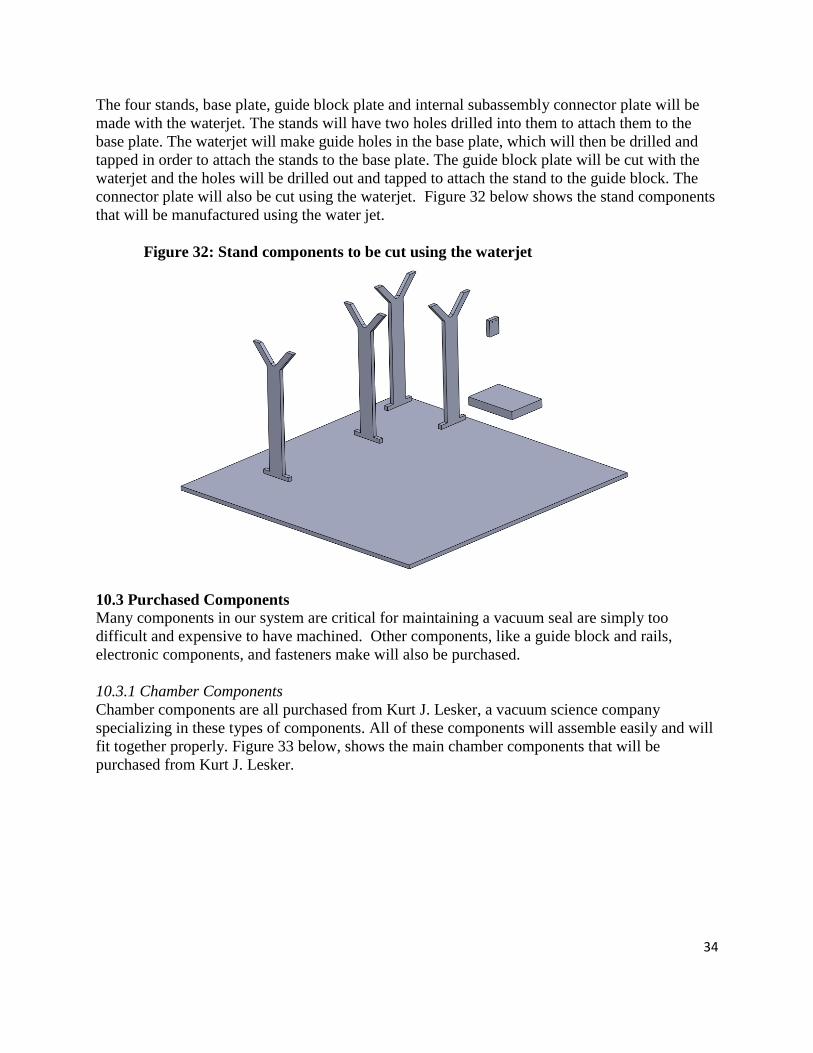
The four stands, base plate, guide block plate and internal subassembly connector plate will be
made with the waterjet. The stands will have two holes drilled into them to attach them to the
base plate. The waterjet will make guide holes in the base plate, which will then be drilled and
tapped in order to attach the stands to the base plate. The guide block plate will be cut with the
waterjet and the holes will be drilled out and tapped to attach the stand to the guide block. The
connector plate will also be cut using the waterjet. Figure 32 below shows the stand components
that will be manufactured using the water jet.
Figure 32: Stand components to be cut using the waterjet
10.3 Purchased Components
Many components in our system are critical for maintaining a vacuum seal are simply too
difficult and expensive to have machined. Other components, like a guide block and rails,
electronic components, and fasteners make will also be purchased.
10.3.1 Chamber Components
Chamber components are all purchased from Kurt J. Lesker, a vacuum science company
specializing in these types of components. All of these components will assemble easily and will
fit together properly. Figure 33 below, shows the main chamber components that will be
purchased from Kurt J. Lesker.

35
Figure 33: Chamber components purchased from Kurt J. Lesker
The most difficult manufacturing process for the chamber are two dowels that need to be press-
fit through the electric feedthrough flange. This will be a challenging step of the manufacturing
process for us and will need to be done very precisely to allow the system tray to attach to the
flange, as well as the flange stand to hold up the tray.
Our design calls for four quartz rods and one quartz tube. These components will be purchased
from G. Finkenbeiner Inc. and can be seen in Figure 16.
10.3.2 Stand Components
The flange stand is composed of a post holder, post, base adapter and clamping forks which are
purchased from Thor Labs. Also purchased from Thor Labs is the V-Mount and right angle plate
which are used as to hold the IR sensor. Figure 34 below shows the components purchased from
Thor Labs.
Figure 34: Components purchased from Thor Labs

36
10.3.3 Miscellaneous Components
The IR sensor will be purchased from Exergen. The miscellaneous screws, set screws, dowel
pins, and shaft collars will be purchased from McMaster-Carr. Also purchased from McMaster
Carr is the guide block and rail. An RF generator and matching network will either be borrowed
from the Nanofabrication Lab at the University of Michigan, or will be purchased from PTB
sales. A 1/4 inch diameter copper wire will be purchased to make the plasma coil, but a vendor
has not been chosen yet.
10.4 Assembly
This section will detail how all of the components are assembled to produce the final prototype.
Figure 35 is a flow chart that shows the major steps for assembling the prototype, as well as the
general order of completion.
Figure 35: A flow chart illustrating the steps system assembly process
10.4.1 Chamber Assembly
The chamber assembly contains all of the Kurt J. Lesker components as well as the quartz tube.
Before the chamber can be fully assembled the dowels must be press-fit into the electrical
feedthrough flange. Once this is complete, all of the flanges easily attach to the six-way cross
using clamps. The quartz tubing is attached using a quick connect on each end, that are attached
using the same type of clamps as the chamber flanges.
Make stands
and base plate
Assemble
chamber
Press-fit dowels
into electrical
feedthrough
flange
Assemble
IR mount
Assemble
system tray
Make system
tray waterjet
components
Attach rail to
base plate
Attach electrical
feedthrough to
stand
Assemble
flange stand
Attach flange
stand to guide
block
Make guide block
plate and
connector plate
Finished
prototype
START

37
10.4.2 System Tray Assembly
The system tray assembly contains the system tray, heatsinks, four quartz rods, the electrode,
four plates, a silicon wafer, two silver tipped set screws, and two shaft collars. Two quartz rods
lay in the system tray, on top of which the two heatsinks are placed. The silicon wafer is placed
between the two heatsinks and the plates are placed on top to secure it. The smaller two quartz
rods are placed standing up in the tray where two holes have been made for them. The electrode
is slid onto the standing rods and secured with two set screws. The tray is then attached to the
press-fit dowel pins with two shaft collars. A picture of the system tray assembly can be seen in
Figure 13.
10.4.3 System Tray Stand
The system tray stand contains the rail, guide block, guide block plate, connector plate, stand,
and two shaft collars. The electrical feedthrough flange is attached to the stand using the
connector plate and secured with two shaft collars. Then the guide block plate is connected to the
guide block and the stand, which is attached to the guide block flange. A picture of the system
tray stand can be seen in Figure 15.
10.4.4 Miscellaneous Components
The rail and stands will be attached to the base plate by bolts. The IR sensor mount will be
attached to a right angle bracket and then bolted to the base plate.
11.0 Usability Analysis
INITIAL SET-UP
Mount the flange holding the substrate holder to the chamber. Do not place the substrate inside the
chamber at this point.
Mount the quartz tube to the chamber and slide in the inductive coil around the tube. Connect the gas
tubing to the inlet of the quartz tube and connect the outlet of the chamber to the pump.
Slide out the flange containing the substrate holder inside the chamber.
Connect all the electrical feedthroughs from the flange holder the substrate holder to the electrodes.
Mount the substrate to the substrate holder and gently slide in the flange into the chamber.
Complete the electrical connections in the flange by connecting the feedthrough to a DC power
supply. Do not turn on the power supply.
Connect the coil to the matching network, and the matching network to the RF power generator and
the automatic matching network controller. Do not turn on the power yet.
Ensure that all flanges and viewports are in place and that the chamber is completely sealed.
PROCESS SET-UP
Evacuate the chamber to a low pressure by flowing through the chamber an inert gas such as helium.
Turn on the gas flow rates to the desired level.
Turn on the RF generator to the desired power level by setting the forward power option in the
generator, and wait till plasma is generated in the quartz tube.
Ensure that the source impedance (50 Ω) matches the complex load (plasma) impedance by tuning the
matching network as necessary, so that maximal power is transferred between the source and load.
Turn off the generator, the flow rates and the vacuum after a specified amount of time, after which the
CNT growth process has reached its final stages or reached a desired level.
38
Wait for a few minutes before attempting to dismount the flange and the substrate holder to access the
substrate.
Carefully, disconnect all electrical connections (recommended) and remove the substrate.
If DC source was to be chosen, then this would have been used instead of the RF generator and an
additional step of removing the electrode before accessing the substrate would be encountered.
CLEANING THE CHAMBER AND QUARTZ TUBE
Ensure that all power supplies, vacuum pumps and gas flow rates are turned off.
Disconnect the quartz tube from any hosing.
Remove the coil from the tube.
Carefully, unmount the quartz tube by removing the flange connecting the tube to the chamber.
For the chamber, slide off the flange carrying the substrate holder slowly.
Remove/ disconnect any other flanges or hosing connecting to the chamber, such that the inner
chamber can now be accessed and cleaned.
CHANGING ELECTRODES AND THE QUARTZ TUBE HOLDING THE ELECTRODE
Carefully, slide off the flange carrying the substrate holder.
Loosen the set-screws holding the electrode on the vertical quartz tubes and slide it off gently.
Remove the tubes from the substrate holder so that they can be cleaned or replaced as desired.
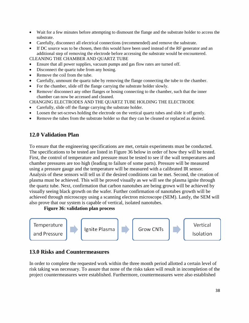
12.0 Validation Plan
To ensure that the engineering specifications are met, certain experiments must be conducted.
The specifications to be tested are listed in Figure 36 below in order of how they will be tested.
First, the control of temperature and pressure must be tested to see if the wall temperatures and
chamber pressures are too high (leading to failure of some parts). Pressure will be measured
using a pressure gauge and the temperature will be measured with a calibrated IR sensor.
Analysis of these sensors will tell us if the desired conditions can be met. Second, the creation of
plasma must be achieved. This will be proved visually as we will see the plasma ignite through
the quartz tube. Next, confirmation that carbon nanotubes are being grown will be achieved by
visually seeing black growth on the wafer. Further confirmation of nanotubes growth will be
achieved through microscopy using a scanning electron microscope (SEM). Lastly, the SEM will
also prove that our system is capable of vertical, isolated nanotubes.
Figure 36: validation plan process
13.0 Risks and Countermeasures
In order to complete the requested work within the three month period allotted a certain level of
risk taking was necessary. To assure that none of the risks taken will result in incompletion of the
project countermeasures were established. Furthermore, countermeasures were also established

39
to surmount any anticipated potential problems. The identified risks, anticipated problems, and
their associated countermeasures are summarized in Table 6 below.
Table 6: Countermeasures to overcome risks and anticipated potential problems
Risk or Anticipated Problem Countermeasure(s)
Overheating of O-ring used to seal quartz tube Purchase quartz tube with fixed metal flanges
Using an alternate pump Rent or borrow a pump capable of the
optimum operating conditions

40
APPENDICES
APPENDIX A: Example of CNT growth

41
APPENDIX B: Customer Specifications and Engineering Requirements
Customer Requirements and Relative Importance Engineering Requirements Target Value
Capable of vertically aligned CNTs 10 Anode – cathode area(mm) Minimize
Effective but variable plasma source 9 Power requirement(W) Minimize
Substrate size 5 Substrate size(mm) ≥ 15 x 15
Adjustable gap between electrodes 7 Adjustable gap size(mm) 10
Precise and non-contact temperature
measurement
6 Accuracy of IR temperature
Measurement(°C)
± 2
View of substrate 2 Viewing Area(cm) Maximize
Variable and stable pressure operation 5 Pressure(Torr) 10-3
-20
Easy exchange of sample 4 Material compatibility(%) 100
Minimum chamber size 3 Volume of chamber(m3) Minimize
Cost 2 Price($) Minimize
Temperature Range(°C) 500 - 900
Flow rate (sccm) 0 – 100

42
APPENDIX C: Comparison of plasma generation techniques
Inductively
Coupled DC Microwave RF - Triode
Op. Temp 700-900 C 520-750 C 660-1000 C 500-600 C
Op Pressure 1-20 torr .005 - 4 Torr 10 - 30 Torr .0075 - .3 Torr
Power 0-200W, 0-300W 50-500W 400-1100 W 50-100W
frequency 13.56 MHz
Plasma gases
hydrogen-metane (80:20)
hydrogen-ethylene (80:20)
Ammonia-acetelyne-hydrogen
Methane-hydrogen methane-ammonia ammonia-acetalyne
acetelyne-hydrogen ethalyne-hydrogen
Catalyst Ti, Ni Iron Colbalt Nickle Iron, Ni
gas flow rate 20-100 sccm
80 sccm NH4-30:70 C2H2 sccm
50 - 240 sccm 1 sccm-9 sccm
tube dia 6-30 nm 100nm-microscale 30 nm 10-20nm
tube length 12 - 100 um 2-10 micro m
Substrate Si
Si, Si/Pt, 25x50 mm Alumina, 2" Si,
2” Si & glass substrate
Growth time 2 - 45 min 2 hr
Min Pressure req.
10^-5 Torr 10^-5 Torr 10^-5 Torr 10^-5 Torr

43
APPENDIX D: PAIRWISE COMPARISON
Customer
Specification
Essential? PAIRWISE COMPARISONS TOTAL WEIGHT
View of substrate X 0 0 1 1 2 0.2
Substrate size X 1 1 0 1 3 0.3
Easy exchange of
sample
X 1 0 1 1 3 0.3
Minimum chamber
size
Χ 0 1 0 1 2 0.2
Cost Χ 0 0 0 0 0
Adjustable gap
between electrodes
10 1
Capable of vertically
aligned carbon
nanotubes
10 1
Effective but variable
plasma source
10 1
Precise and non-
contact temperature
measurement
10 1
Variable and stable
pressure operation
10 1

44
APPENDIX E: QFD

45
APPENDIX F: Submodule concept sketch

46
APPENDIX G: BOM
Item # Vendor Part# Item name
Function or module Leadtime Qty
Unit (each, box, etc.)
Unit price TOTAL
1 Lesker QF50-200-6X 6-way cross Chamber In Stock 1 1 306 306
2 Lesker QF50-200-VP viewport Chamber viewports In Stock 3 1 106.25 318.75
3 Lesker QF50XVC100 KF50 quick connect
Chamber side tube connection In Stock 1 1 78.2 78.2
4 Lesker QF25XVC100 KF25 quick connect
Inlet side tube connection In Stock 1 1 68 68
5 Lesker QF25X4SWG
KF25 swagelok adapter
Inlet swagelok adapter In Stock 1 1 51 51
6 Lesker QF50-200-CHP
KF50 lever clamp
flange sealing In Stock 6 1 17 102
7 Lesker QF25-100-CHP
KF25 lever clamp
attach inlet to quartz tube In Stock 1 1 14.31 14.31
8 Lesker QF50-200-SRV
KF50 center ring
seal between flanges In Stock 6 1 11.9 71.4
9 Lesker QF25-100-SRV
KF25 center ring
seal between flanges In Stock 1 1 6.8 6.8
10 Lesker EFT0083038C
weldable flange and feedthrough
electric feedthrough 1 week 1 1 188.06 188.06
11 Lesker QF50XQF16
Nipple reducing QF50 to QF16
Attach outlet hose to chamber In Stock 1 1 42.5 42.5
12 McMaster-Carr 98381A428 steel pin
Press-fit pin, attach boat to flange In stock 2 1 3.4 6.8
13 McMaster-Carr 6462K71 shaft collar
Hold pins onto boat and block In Stock 4 1 2.46 9.84
14 McMaster-Carr 99934A140
soft tip set screw
Hold up electrode on rods In Stock 2 5 5 10
15 McMaster-Carr 91830A401
thumb screw
hold heating wafer to heat sinks In Stock 2 1 4.38 8.76

47
16 McMaster-Carr 3249K3
Lockable Plain Bearing Guide Block
Moving boat into/out of chamber In Stock 1 1 71.84 71.84
17 McMaster-Carr 9867K13 Guide Rails
Moving boat into/out of chamber In Stock 1
500 mm 65 65
18 Thor Labs VC3 Fixed V-Clamp
IR Sensor Holder In Stock 1 1 42.3 42.3
19 Thor Labs PH3-ST 3 in Post Holder
Height Adjustment In Stock 1 1 8.27 8.27
20 Thor Labs TR3 OD1/2" x 3" post
Height Adjustment In Stock 1 1 5.42 5.42
21 Thor Labs BE1
Pedestal Base Adapter - Imperial Stand In Stock 1 1 9.1 9.1
22 Thor Labs CF125
Small Clamping Fork Stand In Stock 1 1 8.3 8.3
23 Exergen IRt/c.4ALF LoE IR Sensor
Temp. Sensor
In Stock 1 1
735
735
24 ENI ENI ACG-5 ENI 5D
RF generator + matching network In Stock 1 1 5000
25 Varian VHS-6 Vacuum Pump In Stock 1 1 7000
48
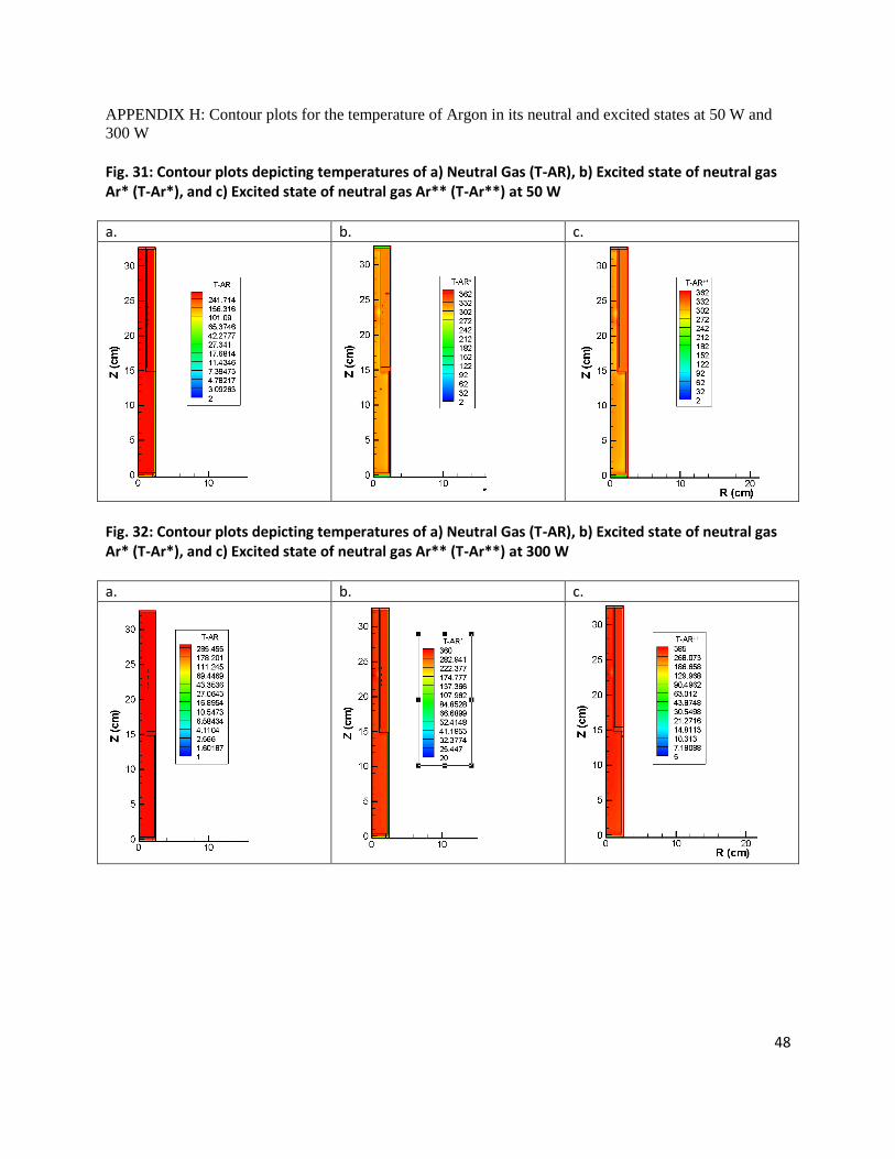
APPENDIX H: Contour plots for the temperature of Argon in its neutral and excited states at 50 W and
300 W
Fig. 31: Contour plots depicting temperatures of a) Neutral Gas (T-AR), b) Excited state of neutral gas Ar* (T-Ar*), and c) Excited state of neutral gas Ar** (T-Ar**) at 50 W
a. b. c.
Fig. 32: Contour plots depicting temperatures of a) Neutral Gas (T-AR), b) Excited state of neutral gas Ar* (T-Ar*), and c) Excited state of neutral gas Ar** (T-Ar**) at 300 W
a. b. c.
49
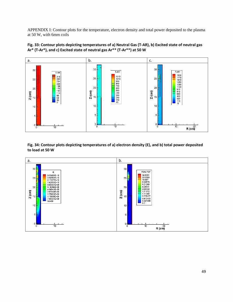
APPENDIX I: Contour plots for the temperature, electron density and total power deposited to the plasma
at 50 W, with 6mm coils
Fig. 33: Contour plots depicting temperatures of a) Neutral Gas (T-AR), b) Excited state of neutral gas Ar* (T-Ar*), and c) Excited state of neutral gas Ar** (T-Ar**) at 50 W
a. b. c.
Fig. 34: Contour plots depicting temperatures of a) electron density (E), and b) total power deposited to load at 50 W
a. b.

50
PECVD system 11/11/2008
Risk Level Report
Application: PECVD system Analyst Name(s): Janani Viswanathan, Bryan yamasaki, Kyler Nicholson, John taphouse
ME 450 plasma Enhanced Chemical Vapor Deposition System for growing carbon nanotubes
Description: Company: University of Michigan
Facility Location: Mechanosynthesis Lab Product Identifier: Assessment Type: Detailed
Limits: Sources:
Guide sentence: When doing [task], the [user] could be injured by the [hazard] due to the [failure mode].
/Reference Hazard /
Task User /
Failure Mode /Comments Responsible /
Risk Level Exposure Probability
Severity Final Assessment
Risk Level Probability Exposure Severity Initial Assessment
Risk Reduction Methods / Status /
Low
Minimal Occasional Unlikely
Serious Occasional Possible
High
mechanical : fatigue O-ring - Tempertaure can exceed O-ring specification
All Users All Tasks
Replace O-rings
Low
Minimal None Negligible
Catastrophic Remote Possible
High
electrical / electronic : energized equipment / live parts 300W Power supply, bare wires inside chamber with Dc current, 500V Dc bias inside chamber
All Users All Tasks
Make sure all power supplies are turned off before handling
Low
Minimal None Negligible
Catastrophic Remote Possible
High
electrical / electronic : lack of grounding (earthing or neutral) Chamber might not be grounded properly
All Users All Tasks
Check if all connections are done properly
Slight Occasional Probable
High
electrical / electronic : shorts / arcing / sparking Between the electrodes and the substrate in the presence of plasma
All Users All Tasks
Low
Slight None Unlikely
Catastrophic Remote Possible
High
electrical / electronic : improper wiring Electrodes not connected properly to power supply, power supply not matched to load
All Users All Tasks
Check if all connections made properly
Low
Minimal None Negligible
Slight None Possible
Low
electrical / electronic : power supply interruption Power break-out
All Users All Tasks
Turn off power supply
Page 1
APPENDIX J: FMEA Analysis

51
PECVD system 11/11/2008
/Reference Hazard /
Task User /
Failure Mode /Comments Responsible /
Risk Level Exposure Probability
Severity Final Assessment
Risk Level Probability Exposure Severity Initial Assessment
Risk Reduction Methods / Status /
electrical / electronic : electromagnetic susceptibility
All Users All Tasks
Low
Minimal Remote Unlikely
Slight Remote Unlikely
Low
ergonomics / human factors : deviations from safe work practices No gloves while handling Carbon nanotubes
All Users All Tasks
Need to wear gloves to handle carbon nanotubes
Low
Slight None Unlikely
Minimal None Unlikely
Low
fire and explosions : hot surfaces Inner chamber wall temperature at a high temperature durng process
All Users All Tasks
Allow for a few minutes for chamber to cool down before opening it up.
Low
Minimal None Negligible
Catastrophic None Unlikely
Moderate
fire and explosions : flammable gas presence of hydrogen, methane
All Users All Tasks
Check tubings for leakages and all hose connections
Low
Minimal None Negligible
Catastrophic Remote Possible
High
fire and explosions : inadequate egress / evacuation routes If connection to evacuation route is loose/ leakage, can cause environmental concerns
All Users All Tasks
Check outlet connections and tubing
Low
Minimal Remote Unlikely
Serious Frequent Possible
High
heat / temperature : severe heat plasma formation
All Users All Tasks
Do not touch chamber during process
Low
Minimal None Negligible
Slight Remote Negligible
Low
environmental / industrial hygiene : asphyxiants methane in case of leaking is an asphyxiant
All Users All Tasks
Check tubings for leakages and all hose connections
Low
Minimal None Negligible
Minimal Remote Possible
Low
environmental / industrial hygiene : effluent / effluent handling helium, hydrogen, methane flowing through chamber and evacuated
All Users All Tasks
Check tubings for leakages and all hose connections
Low
Minimal None Negligible
Minimal None Negligible
Low
chemical : reaction to / with chemicals hydrogen and methane reacting
All Users All Tasks
Do not open chamber during process
Page 2

52
PECVD system 11/11/2008
/Reference Hazard /
Task User /
Failure Mode /Comments Responsible /
Risk Level Exposure Probability
Severity Final Assessment
Risk Level Probability Exposure Severity Initial Assessment
Risk Reduction Methods / Status /
Low
Minimal None Negligible
Serious None Negligible
Low
chemicals and gases : helium Acute or chronic respiratory conditions may be aggravated by overexposure to this gas
All Users All Tasks
Check tubings for leakages and all hose connections, do not open chamber during process
Low
Minimal None Negligible
Serious Remote Unlikely
Moderate
chemicals and gases : hydrogen flammable
All Users All Tasks
Check tubings for leakages and all hose connections
Low
Minimal None Negligible
Serious Remote Unlikely
Moderate
chemicals and gases : methane flammable, At high concentration methane acts as an asphyxiant, fire, explosion
All Users All Tasks
Check tubings for leakages and all hose connections
Low
Minimal None Negligible
Serious Remote Unlikely
Moderate
biological / health : asphyxiant presence of methane
All Users All Tasks
Check for leakages
Low
Minimal None Negligible
Serious Remote Unlikely
Moderate
biological / health : eye contact in case of leakage, methane causes eye irritation
All Users All Tasks
Check for leakages, if not wear safety glasses
Low
Minimal None Negligible
Serious Remote Unlikely
Moderate
biological / health : skin contact in case of leakage, methane causes skin irritation
All Users All Tasks
Check for leakages
Low
Slight None Possible
Minimal Frequent Probable
High
fluid / pressure : vacuum Improper chamber evacuation might cause system not to work
All Users All Tasks
Make sure not to touch the inner chamber walls or wear gloves, all connections are properly connected/ sealed
Low
Minimal None Negligible
Serious Remote Unlikely
Moderate
fluid / pressure : fluid leakage / ejection in tubing connections
All Users All Tasks
Check tubings for leakages and all hose connections
Low
Minimal None Negligible
Serious Remote Unlikely
Moderate
radiation : high-speed electrons breakdown of reactant gases to ions and electrons
All Users All Tasks
Do not open chamber during process
Page 3

53
APPENDIX K: Engineering drawings: system tray and heat sinks
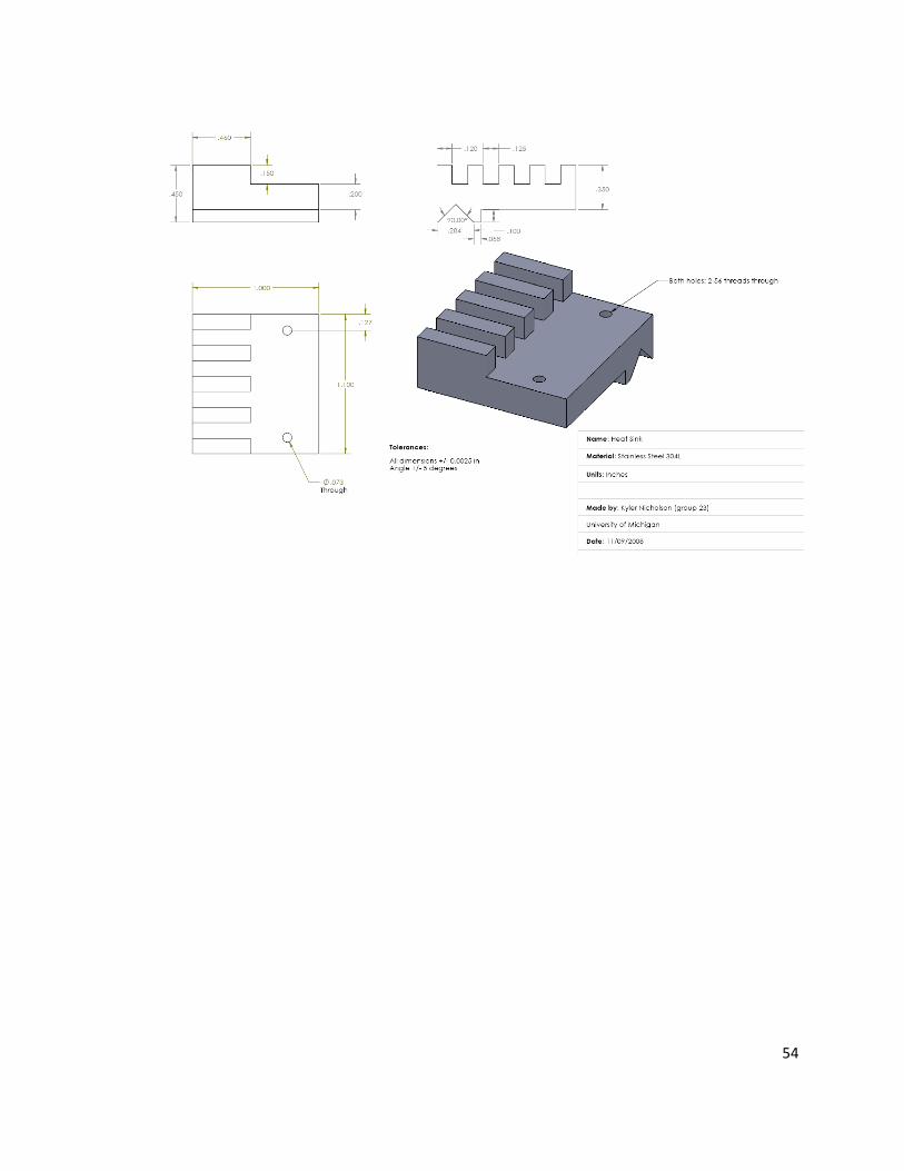
54
55
REFERENCES
[1] Li, J., Ye Q., Cassel A., Ng, H., Stevens, R., Han, J., and Meyyappan, M., 2003, “Bottom Up
Approach for Carbon Nanotube Interconnects,” Applied Physics Letters, 85(15), pp. 2491-2493
[2] Delzeit, L., McAninch, I., Cruden, B., Hash, D., Chen, B., Han, J., and Meyyappan, M., 2002,
“Growth of Multiwall Carbon Nanotubes in an Inductively Coupled Plasma Reactor,” Journal of Applied
Physics, 91(9), pp. 6027-6033
[3] Delzeit, L., Nguyen, C., Stevens, R., Han, J., and Meyyappan, M, 2002, “Growth of Carbon
Nanotubes by Thermal and Plasma Chemical Vapor Deposition Process and Applications in
Microscopy,” Institute of Physics Publishing: Nanotechnology, 13, pp. 280-284
[4] Mathews, K., Cruden, B. Chen, B., Meyyappan, M., and Delzeit, L., 2002, “Plasma-Enhanced
Chemical Vapor Deposition of Multiwalled Carbon Nanofibers,” Journal of Nanoscience and
Nanotechnology, 2(5), pp. 475-480
[5] Cui, H., Zhou, O., and Stoner, B., “Deposition of Aligned Bamboo-Like Carbon Nanotubes Via
Microwave Plasma Enhanced Chemical Vapor Deposition,” Journal of Applied Physics, 88(10), pp.
6072-6074
[6] Tsia, C., Chen, C., and Wu, L., “Bias Effect on the Growth of Carbon Nanotips Using Microwave
Plasma Chemical Vapor Deposition,” Applied Physics Letters, 81(4), pp. 721-723
[7] Qin, L., Zhou, D., Krauss, A., and Gruen, D., 1998, “Growing Carbon Nanotubes Using Microwave
Plasma-Enhanced Chemical Vapor Deposition,” Applied Physics Letters, 72(26), pp. 3437-3439
[8] Bower, C., Zhu, W., Jin, S., and Zhou, O., 2000, “Plasma Induced Alignment of Carbon Nanotubes,”
Applied Physics Letters, 77(6), pp. 830-832
[9] Bower, C., Zhou, O., Zhu, W., Werder, J., and Jin, S., 2002, “Nucleation and Growth of Carbon
Nanotubes by Microwave Plasma Chemical Vapor Deposition,” Applied Physics Letters, 77(17), pp.
2767-2769
[10] Tsia, S., Chao, C., Lee, C., and Shih, H., 1999, “Biased-Enhanced Nucleation and Growth of the
Aligned Carbon Nanotubes with Open Ends with Microwave Plasma Synthesis,” Applied Physics Letters,
74(23), pp. 3462-3464
[11] Choi, Y., Shin, Y., Lim, S., Bae, D., Lee, Y., and Lee, B., 2000, “Effect of Surface Morphology of
Ni Thin Film on the Growth of Aligned Carbon Nanotubes by Microwave Plasma-Enhanced Chemical
Vapor Deposition,” Journal of Applied Physics, 88(8), pp. 4898-4903
[12] Hopwood, J., 1992, “Review of Inductively Coupled Plasmas for Plasma Processing,” Plasma
Sources Sci. Technol., 1, pp. 109-116
[13] Conrads, H., Schmidt, M., 2000, “Plasma Generation and Plasma Sources,” Plasma Sources Sci.
Technol, 9, pp. 441-454

56
[14] Hyun, D., Shin, D., Lee, W., and Kim, S., 2008, “Hierarchically Organized Carbon Nanotube Arrays
from Self-Assembled Block Copolymer Nanotemplates,” Advanced Materials, 20, pp. 2480-2485
[15] Qi, H., Teo, K., Lau, K., Boyce, M., Milne, W., Robertson, J., and Gleason, K., 2003,
“Determination of Mechanical Properties of Carbon Nanotubes and Vertically Aligned Carbon Nanotube
Forests using Nanoindentation,” Journal of the Mechanics and Physics of Solids, 51, pp. 2213-2237
[16] Semet, V., Binh, V., Guillot, D., Teo, K, Chhowalla, M., Amaratunga, G., Milne, W., Legagneax, P.,
and Pribat, D., 2005, “Reversible Electromechanical Characteristics of Individual Multiwall Carbon
Nanotubes,” Applied Physics Letters, 87(22)
[17] Li, Y., Mann, D., Rolandi, M., Kim, W., Ural, A., Hung, S., Javey, A., Cao, J., Wang, D., Yenilmez,
E., Wang, Q., Gibbons, J., Nishi, Y., and Dai, H., 2004, “Preferential Growth of Semiconducting Single-
Walled Carbon Nanotubes by a Plasma Enhanced CVD Method,” Nano Letters, 4(2), pp. 317-321
[18] Bell, M., Lacerda, R., Teo, K., and Milne, W., 2006, “Characterisation of the Growth Mechanism
During PECVD of Multiwalled Carbon Nanotubes,” Topics Appl. Phys., 100, pp. 77-93
[19] Merkulov, V., Guillorn, M., Lowndes, D., and Simpson, M., 2001, “Shaping Carbon Nanostructures
by Controlling the Synthesis Process,” Applied Physics Letters, 79(8), pp. 1178-1180
[20] Guillorn, M., Simpson, M., Bordonaro, G., Merkulov, V., Baylor, L., and Lowndes, D., 2001,
“Fabrication of Gated Cathode Structures Using an In Situ Grown Vertically Aligned Carbon Nanofiber
as a Field Emission Element,” Vac. Sci. Technol., 19(2), pp. 573-578
[21] Guillorn, M., Melechko, A., Merkulov, V., Ellis, E., Simpson, M., Lowndes, D., Baylor, L., and
Bordonaro, G., 2001, “Microfabricated Field Emission Devices using Carbon Nanofibers as Cathode
Elements,” Vac. Sci. Technol., 19(6), pp. 2598-2601
[22] Mayyappan, M., Delzeit, L., Cassel, A., and Hash, D., 2003, “Carbon Nanotube Growth by PECVD:
A Review,” Institute of Physics Publishing, 12, pp. 205-216
[23] Shiratori, Y., Hiraoka, H., and Yamamoto, M., 2004, “Vertically Aligned Carbon Nanotubes
Produced by Radio-Frequency Plasma-Enhanced Chemical Vapor Deposition at Low Temperature and
their Growth Mechanism,” Materials Chemistry and Physics, 87, pp. 31-38
[24] Show, Y., and Fukuzumi, N., 2007, “Selective Growth of CNT by Using Triode Type Radio
Frequency Plasma Chemical Vapor Deposition Method,” Diamond and Releted Materals, 16, pp. 1106-
1109
[25] Show, Y., Yabe, Y., Izumi, T., and Yamauchi, H., 2005, “Development of Triode Type RF Plasma
Enhance CVD Equipment for Low Temperature Growth of Carbon Nanotubes,” Diamond and Related
Materials, 14, pp. 1848-1851
[26] Yabe, Y., Ohtake, Y., Ishitobi, T., Show, Y., Izumi, T., and Yamauchi, T., 2004, “Synthesis of Well-
Aligned Carbon Nanotubes by Radio Frequency Plasma Enhanced CVD Method,” Diamond and Related
Materials, 13, pp. 1292-1295

57
[27] Ford, N., 2007, “Plasma Enhanced Growth of Carbon Nanotubes,” Ph.D. thesis, Oregon State
University
[28] The United States Patent and Trademark Office website, www.uspto.gov
[29] Dr. John Foster, Director of the Plasma Science and Technology Lab, University of Michigan
[30] Dr. Mark Kushner, Director of the Michigan Institute for Plasma Science and Engineering,
University of Michigan
[31] CES EduPak, Granta Design Limited 2008
[32] Michigan Tech, Department of Mechanical Engineering website, www.me.mtu.edu
[33] Varian Inc., Varian website, www.varianinc.com
[34] Kurt J. Lesker VacuCAD Service, www.lesker.com
[35] Thor Labs Support Documentation, www.thorlabs.com
[36] Simapro LCA software, Product Ecology Consultants
[37] Designsafe, Design Safety Engineering, Inc. 2008