ENGINE COMBUSTION NETWORK
87
ENGINE COMBUSTION NETWORK ECN6 Topic 9 : Internal and Near Nozzle Flow Gasoline Spray Organizer & Presenter: David P. Schmidt Chinmoy K. Mohapatra UMass, Amherst
Transcript of ENGINE COMBUSTION NETWORK

ENGINE COMBUSTION NETWORK
ECN6 Topic 9 :
Internal and Near Nozzle Flow Gasoline Spray
Organizer & Presenter:
David P. Schmidt
Chinmoy K. Mohapatra
UMass, Amherst

CONTRIBUTORS
David Schmidt, Chinmoy Mohapatra, UMass, Amherst
Pedro Marrtí , María Martínez, CMT-Motores Térmicos
Dimitrios Papoulias, Samir Muzaferija, Kshitij Nerrorkar , Siemens CD Adapco
Zongyu Yue, Sibendu Som, Argonne National Laboratory
Boxiong Chen, Michael Oevermann, Chalmers University
Balalji Mohan, Hong G. Im, Jihad A Badra, KAUST
Mathis Bode, RWTH Aachen University
2
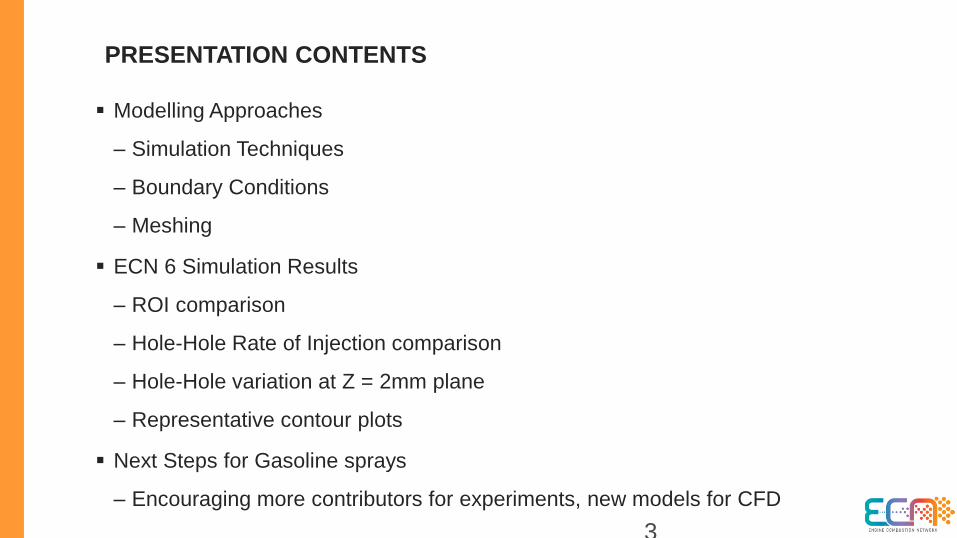
Modelling Approaches
– Simulation Techniques
– Boundary Conditions
– Meshing
ECN 6 Simulation Results
– ROI comparison
– Hole-Hole Rate of Injection comparison
– Hole-Hole variation at Z = 2mm plane
– Representative contour plots
Next Steps for Gasoline sprays
– Encouraging more contributors for experiments, new models for CFD
3
PRESENTATION CONTENTS

SPRAY G , G2 , G3 NOMINAL OPERATING CONDITIONS
Condition SprayG SprayG2 SprayG3
Fuel Isooctane Isooctane Isooctane
Injection
Pressure
20 MPa 20MPa 20MPa
Fuel Temperature 90° C (363.15 K) 90° C (363.15 K) 90° C (363.15 K)
Ambient
Temperature
300° C (573.15 K) 60° C (333.15 K) 60° C (333.15 K)
Ambient Density 3.5 kg/m3 0.5 kg/m3 1.2 kg/m3
Back Pressure 600 kPa (N2) 50 kPa (N2) 100 kPa (N2)
Injected Quantity 10 mg 10 mg 10 mg
Injection Duration 780 µs (“actual”) 780 µs (“actual”) 780 µs (“actual”)

5
MODELING APPROACHES
6
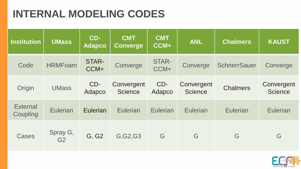
INTERNAL MODELING CODES
Institution UMassCD-
Adapco
CMT
Converge
CMT
CCM+ANL Chalmers KAUST
Code HRMFoamSTAR-
CCM+Converge
STAR-
CCM+Converge SchnerrSauer Converge
Origin UMassCD-
Adapco
Convergent
Science
CD-
Adapco
Convergent
ScienceChalmers
Convergent
Science
External
CouplingEulerian Eulerian Eulerian Eulerian Eulerian Eulerian Eulerian
CasesSpray G,
G2G, G2 G,G2,G3 G G G G
7
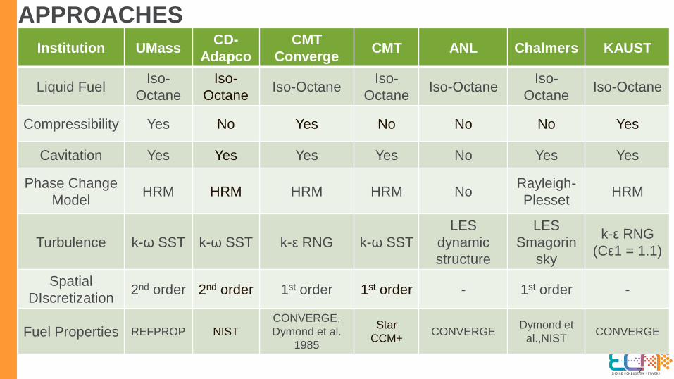
APPROACHES
Institution UMassCD-
Adapco
CMT
ConvergeCMT ANL Chalmers KAUST
Liquid FuelIso-
Octane
Iso-
OctaneIso-Octane
Iso-
OctaneIso-Octane
Iso-
OctaneIso-Octane
Compressibility Yes No Yes No No No Yes
Cavitation Yes Yes Yes Yes No Yes Yes
Phase Change
ModelHRM HRM HRM HRM No
Rayleigh-
PlessetHRM
Turbulence k-ω SST k-ω SST k-ε RNG k-ω SST
LES
dynamic
structure
LES
Smagorin
sky
k-ε RNG
(Cε1 = 1.1)
Spatial
DIscretization2nd order 2nd order 1st order 1st order - 1st order -
Fuel Properties REFPROP NIST
CONVERGE,
Dymond et al.
1985
Star
CCM+CONVERGE
Dymond et
al.,NISTCONVERGE
8
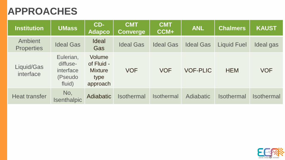
APPROACHES
Institution UMassCD-
Adapco
CMT
Converge
CMT
CCM+ANL Chalmers KAUST
Ambient
PropertiesIdeal Gas
Ideal
GasIdeal Gas Ideal Gas Ideal Gas Liquid Fuel Ideal gas
Liquid/Gas
interface
Eulerian,
diffuse-
interface
(Pseudo
fluid)
Volume
of Fluid -
Mixture
type
approach
VOF VOF VOF-PLIC HEM VOF
Heat transferNo,
IsenthalpicAdiabatic Isothermal Isothermal Adiabatic Isothermal Isothermal

9
COMPUTATIONAL DOMAIN
Institution UMassCD-
Adapco
CMT
Conv.
CMT
CCM+ANL Chalmers KAUST
Dimensionality 3 3 3 3 3 3 3
Cell Type
Hexahedral
with anisotropic
refinement
between needle
and wall
Hex &
prism
cells+
wall
layers
Hex +
wall
layers
Hex &
poly
hedra
with wall
layers
Hex + wall
layers
Hexa-
hedral
cells
Hex +
wall
layers
Meshing Tool Grid Pro Star CCM+ Converge Star CCM+ ConvergeGrid
Pro(refined)Converge
Cell Count 1.5 million 8 million1
million
11.4
million,
5.08
million
- 9.8 million -
Adaptive or
static
refinement
Static Static AMR Static AMR Static AMR
10
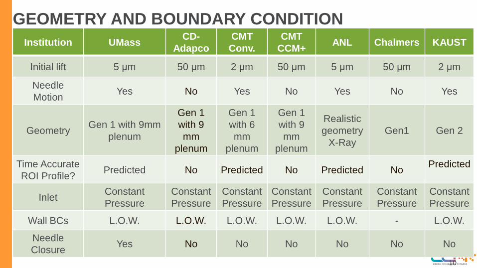
GEOMETRY AND BOUNDARY CONDITION
Institution UMassCD-
Adapco
CMT
Conv.
CMT
CCM+ANL Chalmers KAUST
Initial lift 5 μm 50 μm 2 μm 50 μm 5 μm 50 μm 2 μm
Needle
MotionYes No Yes No Yes No Yes
GeometryGen 1 with 9mm
plenum
Gen 1
with 9
mm
plenum
Gen 1
with 6
mm
plenum
Gen 1
with 9
mm
plenum
Realistic
geometry
X-Ray
Gen1 Gen 2
Time Accurate
ROI Profile?Predicted No Predicted No Predicted No
Predicted
InletConstant
Pressure
Constant
Pressure
Constant
Pressure
Constant
Pressure
Constant
Pressure
Constant
Pressure
Constant
Pressure
Wall BCs L.O.W. L.O.W. L.O.W. L.O.W. L.O.W. - L.O.W.
Needle
ClosureYes No No No No No No

11
NEEDLE LIFT
Data and figure
provided by Dan
Duke at Argonne
National Lab

12
COMPUTATIONAL MESH (UMASS)
• Transient lift based upon ensemble
averaged Argonne measurements
• Laplacian smoothing for mesh motion
• 10 μm and 7 μm grid spacing in the sac
and nozzle hole
13
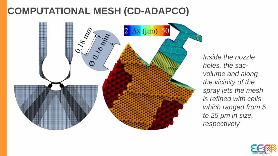
COMPUTATIONAL MESH (CD-ADAPCO)
Inside the nozzle
holes, the sac-
volume and along
the vicinity of the
spray jets the mesh
is refined with cells
which ranged from 5
to 25 μm in size,
respectively

14
HEXAHEDRAL MESH (CMT- STARCCM+)
Base size 140 µm
Cells 11.44 millions
Prism Layer 3
Layer Total
Thickness8.75 µm
Surface Control:
- Minimum cell size: 17.5 µm
- Surface Growth Rate: 1.05
- Trimmer Surface Growth Rate:
Medium
Volumetric Control:
- Minimum cell size: 8.75 µmCell size: 17.5 µmCell size: 35
µm

15
POLYHEDRAL MESH (CMT- STARCCM+)
Base size 60 µm
Cells 5.08 millions
Prism Layer 3
Layer Total
Thickness8.625 µm
Surface Control:
- Minimum cell size: 18 µm
- Surface Growth Rate: 1.05
Volumetric Control:
- Minimum cell size: 18 µm

16
Nozzle
Holes
Chamber
COMPUTATIONAL MESH (CMT- CONVERGE)- Base Size: 140 µm
- Grid Scaling: -1
- Fixed Embedding:
- Region (Nozzle &
Holes)
- Mode: Permanent
- Scale: 3
- Boundary (Nozzle)
- Mode: Permanent
- Scale: 4
- Embed layers: 1
- AMR:
- Chamber & Holes
- Embedding: 4
- Sub-grid criterion:
1.0
- Timing control
type: PermanentCell count at start of simulation: 1.018.865
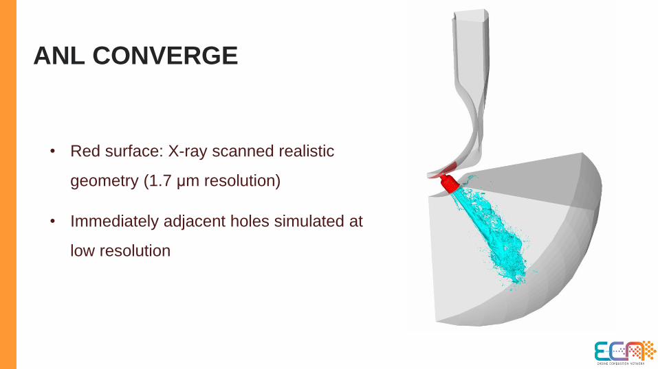
ANL CONVERGE
• Red surface: X-ray scanned realistic
geometry (1.7 μm resolution)
• Immediately adjacent holes simulated at
low resolution

CHALMERS OPENFOAM

19
SIMULATION RESULTS

INTERNAL OBSERVATIONS
CCM+ CD Adapco
Iso-surface of
14MPa total
pressure,
streamlines
Similar to vorticity seen
in Baldwin et al. 2016

21
CAD GeometryHOLE ORIENTATION

22
ROI, MOMENTUM RATE MEASUREMENT LOCATION (NOZZLE EXIT PLANE)
Hole 1
Hole 5
Hole 2
Hole 6
Hole 3 Hole 7
Hole 4
Hole 8

23
RATE OF INJECTION – SPRAY G

24
RATE OF INJECTION – SPRAY G2

25
NCG RATE OF INJECTION

26
VAPOR RATE OF INJECTION
27
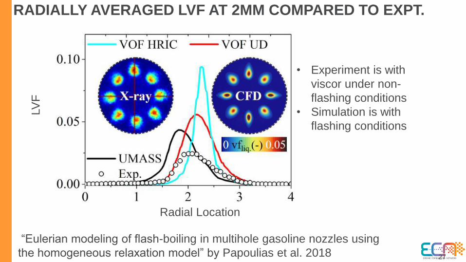
RADIALLY AVERAGED LVF AT 2MM COMPARED TO EXPT.
“Eulerian modeling of flash-boiling in multihole gasoline nozzles using
the homogeneous relaxation model” by Papoulias et al. 2018
• Experiment is with
viscor under non-
flashing conditions
• Simulation is with
flashing conditions
LV
F
Radial Location

28
ROI – HOLE 1
Spray G Spray G2
29
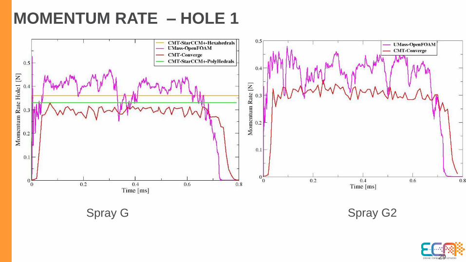
MOMENTUM RATE – HOLE 1
Spray G Spray G2

30
ROI – HOLE 2
Spray G Spray G2

31
MOMENTUM RATE – HOLE 2
Spray G Spray G2

32
ROI – HOLE 3
Spray G Spray G2

33
MOMENTUM RATE – HOLE 3
Spray G Spray G2

34
ROI – HOLE 4
Spray G Spray G2

35
MOMENTUM RATE – HOLE 4
Spray G Spray G2
36
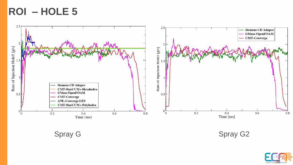
ROI – HOLE 5
Spray G Spray G2

37
MOMENTUM RATE – HOLE 5
Spray G Spray G2

38
ROI – HOLE 6
Spray G Spray G2

39
MOMENTUM RATE – HOLE 5
Spray G Spray G2

40
ROI – HOLE 6
Spray G Spray G2
41
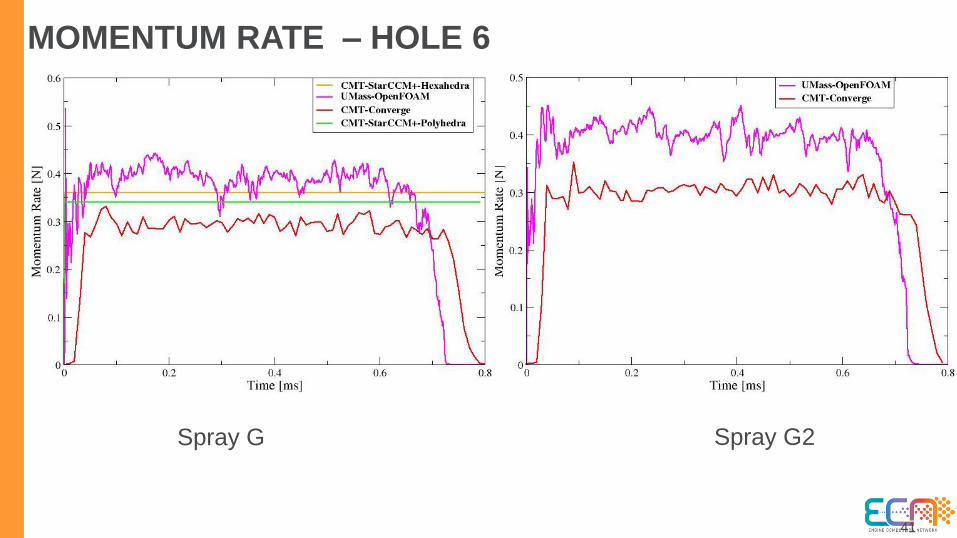
MOMENTUM RATE – HOLE 6
Spray G Spray G2
42
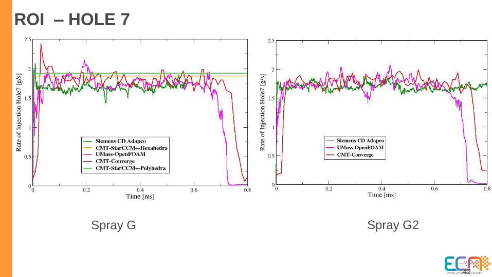
ROI – HOLE 7
Spray G Spray G2

43
MOMENTUM RATE – HOLE 7
Spray G Spray G2
44
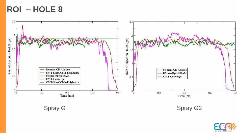
ROI – HOLE 8
Spray G Spray G2

45
MOMENTUM RATE – HOLE 8
Spray G Spray G2
46
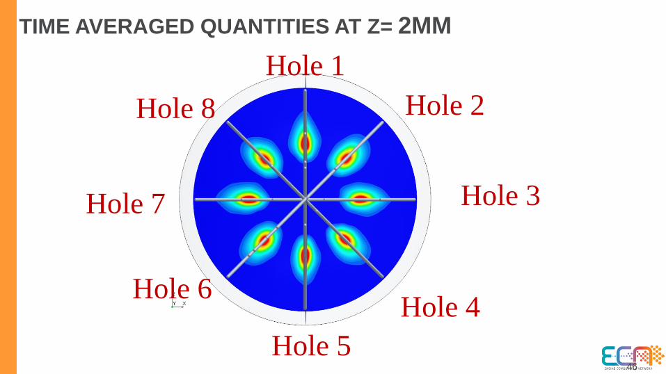
TIME AVERAGED QUANTITIES AT Z= 2MM
Hole 1
Hole 5
Hole 2
Hole 6
Hole 3Hole 7
Hole 4
Hole 8
47
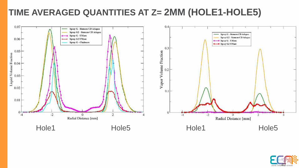
TIME AVERAGED QUANTITIES AT Z= 2MM (HOLE1-HOLE5)
Hole1 Hole5 Hole1 Hole5

48
TIME AVERAGED QUANTITIES AT Z= 2MM(HOLE1-HOLE5)
Hole1 Hole5 Hole1 Hole5

49
TIME AVERAGED QUANTITIES AT Z= 2MM(HOLE2-HOLE6)
Hole2 Hole6 Hole2 Hole6

50
TIME AVERAGED QUANTITIES AT Z= 2MM(HOLE2-HOLE6)
Hole2 Hole6 Hole2 Hole6

51
TIME AVERAGED QUANTITIES AT Z= 2MM(HOLE3-HOLE7)
Hole3 Hole7 Hole3 Hole7

52
TIME AVERAGED QUANTITIES AT Z= 2MM(HOLE3-HOLE7)
Hole3 Hole7 Hole3 Hole7

53
TIME AVERAGED QUANTITIES AT Z= 2MM(HOLE4-HOLE8)
Hole4 Hole8 Hole4 Hole8

54
TIME AVERAGED QUANTITIES AT Z= 2MM(HOLE4-HOLE8)
Hole4 Hole8 Hole4 Hole8
55
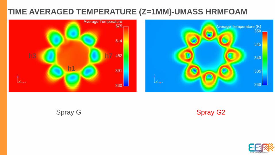
TIME AVERAGED TEMPERATURE (Z=1MM)-UMASS HRMFOAM
Spray G Spray G2
h3 h7
h1

56
TIME AVERAGED TEMPERATURE (Z=1MM)-CMT CONVERGE
Spray G Spray G2
h3 h7
h1

57
TIME AVERAGED TEMPERATURE (Z=1MM)-CHALMERS
Spray G
h3 h7
h1

WHAT IS THE RIGHT ANSWER?
Zhang, Gaoming, David LS Hung, and Min Xu.
"Experimental study of flash boiling spray vaporization
through quantitative vapor concentration and liquid
temperature measurements." Experiments in fluids 55.8
(2014): 1804
Kamoun, H., Lamanna, G., Ruberto, S.,
Komenda, A., Weigand, B., & Steelant, J.
(2014). Experimental investigations of fully
flashing jets.

59
TIME AVERAGED TEMPERATURE AT Z= 1MM (HOLE1-HOLE5)
Hole1 Hole5 Hole1 Hole5
Spray G Spray G2
60
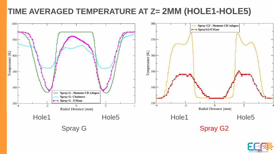
TIME AVERAGED TEMPERATURE AT Z= 2MM (HOLE1-HOLE5)
Hole1 Hole5 Hole1 Hole5
Spray G Spray G2

61
TIME AVERAGED TEMPERATURE AT Z= 1MM (HOLE2-HOLE6)
Hole2 Hole6 Hole2 Hole6
Spray G Spray G2

62
TIME AVERAGED TEMPERATURE AT Z= 2MM (HOLE2-HOLE6)
Hole2 Hole6 Hole2 Hole6
Spray G Spray G2

63
TIME AVERAGED TEMPERATURE AT Z= 1MM (HOLE3-HOLE7)
Hole3 Hole7 Hole3 Hole7
Spray G Spray G2

64
TIME AVERAGED TEMPERATURE AT Z= 2MM (HOLE3-HOLE7)
Hole3 Hole7 Hole3 Hole7
Spray G Spray G2

65
TIME AVERAGED TEMPERATURE AT Z= 1MM (HOLE4-HOLE8)
Hole4 Hole8 Hole4 Hole8
Spray G Spray G2

66
TIME AVERAGED TEMPERATURE AT Z= 2MM (HOLE4-HOLE8)
Hole4 Hole8 Hole4 Hole8
Spray G Spray G2

67
TIME AVERAGED DENSITY AT Z= 2MM (SPRAY G2)
Hole1 Hole5 Hole3 Hole7
68
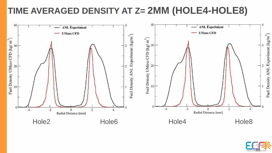
TIME AVERAGED DENSITY AT Z= 2MM (HOLE4-HOLE8)
Hole2 Hole6 Hole4 Hole8

69
DENSITY (NOZZLE & CB EXIT)-CMT CONVERGE
Spray G Spray G2
h1
h3 h7

70
DENSITY (NOZZLE & CB EXIT)-UMASS HRMFOAM
Spray G Spray G2
h1
h3 h7

71
VELOCITY (NOZZLE & CB EXIT)-CMT CONVERGE
Spray G Spray G2h1
h3 h7

72
VELOCITY (NOZZLE & CB EXIT)-UMASS HRMFOAM
Spray G Spray G2
h1
h3 h7
73
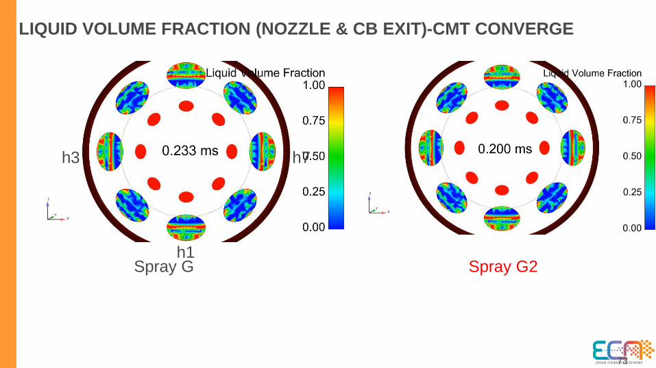
LIQUID VOLUME FRACTION (NOZZLE & CB EXIT)-CMT CONVERGE
Spray G Spray G2h1
h3 h7
74
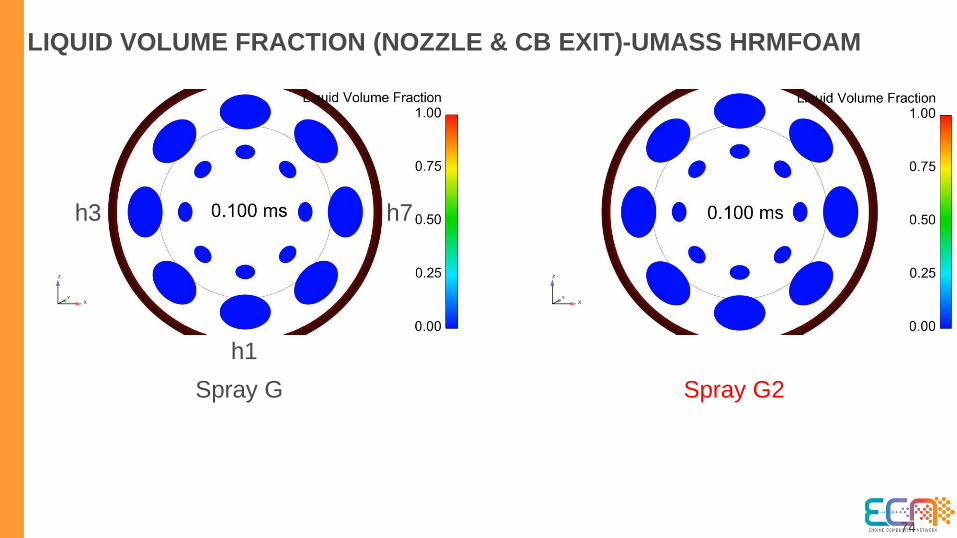
LIQUID VOLUME FRACTION (NOZZLE & CB EXIT)-UMASS HRMFOAM
Spray G Spray G2
h1
h3 h7
75
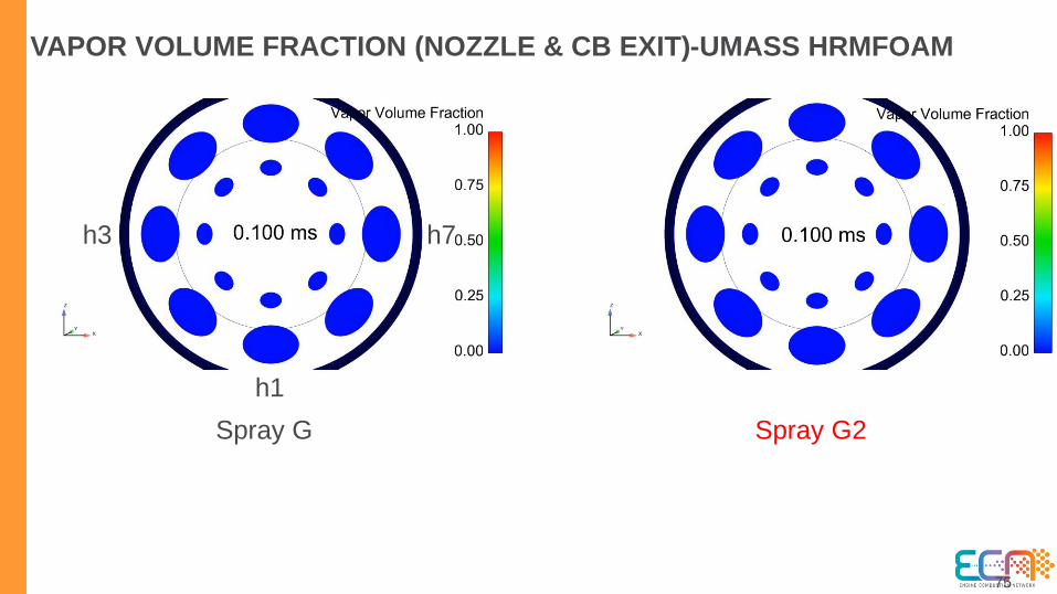
VAPOR VOLUME FRACTION (NOZZLE & CB EXIT)-UMASS HRMFOAM
Spray G Spray G2
h1
h3 h7
76
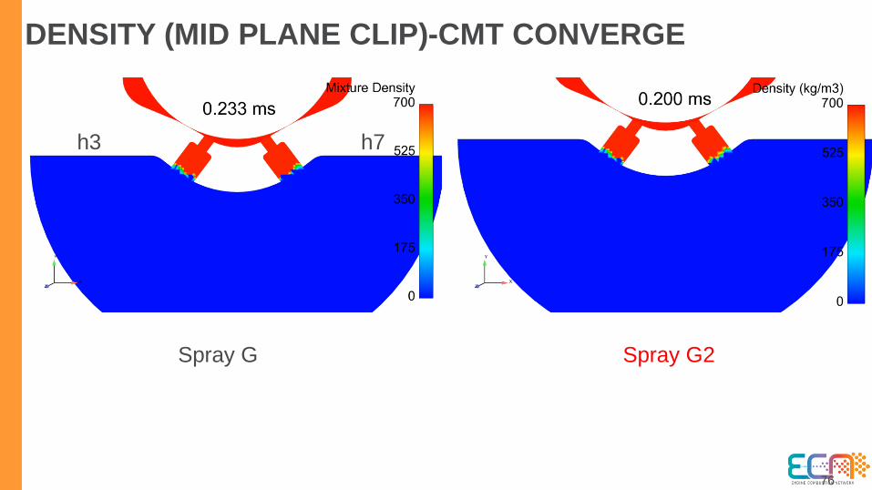
DENSITY (MID PLANE CLIP)-CMT CONVERGE
Spray G Spray G2
h3 h7

77
DENSITY (MID PLANE CLIP)-UMASS HRMFOAM
Spray G Spray G2
h3 h7

78
VELOCITY (MID PLANE CLIP)-CMT CONVERGE
Spray G Spray G2
h3 h7

79
VELOCITY (MID PLANE CLIP)-UMASS HRMFOAM
Spray G Spray G2
h3 h7

80
LIQUID MASS FRACTION (MID PLANE CLIP)-CMT CONVERGE
Spray G Spray G2
h3 h7
81
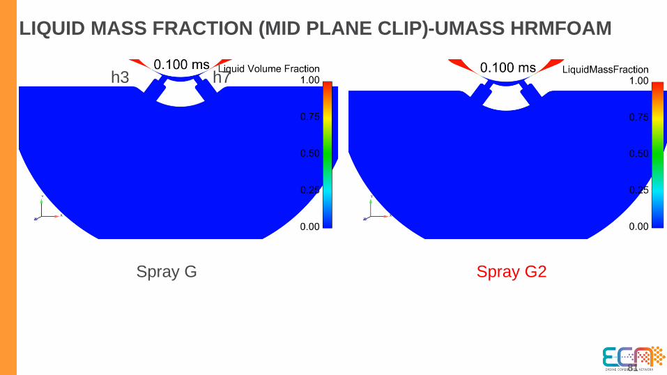
LIQUID MASS FRACTION (MID PLANE CLIP)-UMASS HRMFOAM
Spray G Spray G2
h3 h7

82
LIQUID VOLUME FRACTION (MID PLANE CLIP)-CMT CONVERGE
Spray G Spray G2
h3 h7

83
LIQUID VOLUME FRACTION (MID PLANE CLIP)-UMASS HRMFOAM
Spray G Spray G2
h3 h7
84
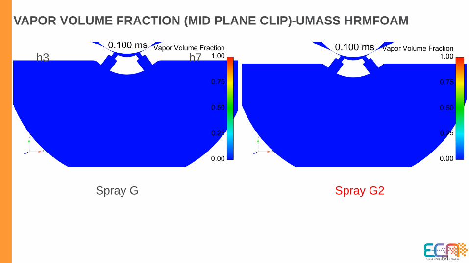
VAPOR VOLUME FRACTION (MID PLANE CLIP)-UMASS HRMFOAM
Spray G Spray G2
h3 h7

85
LIQUID VOLUME FRACTION (SPRAY G)-CHALMERS
h3 h7
h3
h1
Mid plane viewCB and Nozzle exit cut plane view
86
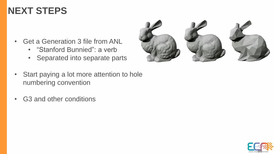
NEXT STEPS
• Get a Generation 3 file from ANL
• “Stanford Bunnied”: a verb
• Separated into separate parts
• Start paying a lot more attention to hole
numbering convention
• G3 and other conditions
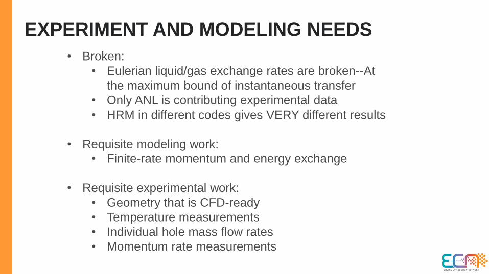
EXPERIMENT AND MODELING NEEDS
• Broken:
• Eulerian liquid/gas exchange rates are broken--At
the maximum bound of instantaneous transfer
• Only ANL is contributing experimental data
• HRM in different codes gives VERY different results
• Requisite modeling work:
• Finite-rate momentum and energy exchange
• Requisite experimental work:
• Geometry that is CFD-ready
• Temperature measurements
• Individual hole mass flow rates
• Momentum rate measurements