Energy Tutorial: Carbon Capture 101
65
GLOBAL CLIMATE AND ENERGY PROJECT | STANFORD UNIVERSITY Energy Tutorial: Carbon Capture 101 Professor Jennifer Wilcox Energy Resources Engineering Department Global Climate and Energy Project Stanford University OCTOBER 5, 2011 GLOBAL CHALLENGES – GLOBAL SOLUTIONS – GLOBAL OPPORTUNITIES GCEP RESEARCH SYMPOSIUM 2011 | STANFORD, CA
Transcript of Energy Tutorial: Carbon Capture 101

GLOBAL CLIMATE AND ENERGY PROJECT | STANFORD UNIVERSITY
Energy Tutorial:
Carbon Capture 101
Professor Jennifer Wilcox Energy Resources Engineering Department
Global Climate and Energy Project
Stanford University
OCTOBER 5, 2011
GLOBAL CHALLENGES – GLOBAL SOLUTIONS – GLOBAL OPPORTUNITIES
GCEP RESEARCH SYMPOSIUM 2011 | STANFORD, CA

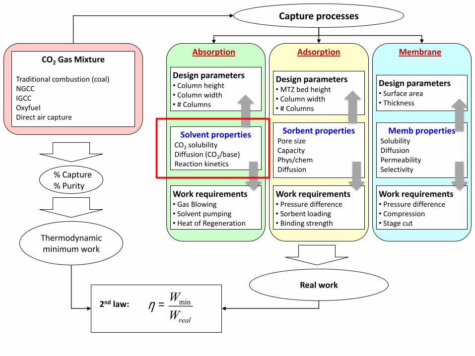
Capture processes
Absorption Adsorption Membrane
Design parameters • Column height • Column width • # Columns
Solvent properties CO2 solubility Diffusion (CO2/base) Reaction kinetics
Design parameters • MTZ bed height • Column width • # Columns
Sorbent properties Pore size Capacity Phys/chem Diffusion
Work requirements • Pressure difference • Sorbent loading • Binding strength
Design parameters • Surface area • Thickness
Memb properties Solubility Diffusion Permeability Selectivity
Work requirements • Pressure difference • Compression • Stage cut
Work requirements • Gas Blowing • Solvent pumping • Heat of Regeneration
2nd law:
Thermodynamic minimum work
CO2 Gas Mixture
Traditional combustion (coal) NGCC IGCC Oxyfuel Direct air capture
Real work
% Capture % Purity
h =Wmin
Wreal

Coal to Electricity
• Furnace is pre-heated by combustion of auxiliary fuel
such as natural gas or oil;
• Pulverized coal powder is blown with air into a
combustion chamber (boiler or furnace) through a
series of nozzles;
• Heat is transferred from hot combustion products to
water circulating in tubes along the boiler walls,
producing superheated steam, which is the working
fluid for the steam turbines;
• Energy from the hot and pressurized steam is
extracted in steam turbines that then transmit the
energy to electric generators;
• The electric generators convert the shaft work of the
turbines into alternating current electricity;
• Pumps are used to return the condensed water to the
boiler, where the cycle is then repeated; and
• Pollution control devices are also in place for NOx,
SOx, PM, and Hg.
*Images courtesy of Y. Liu, SU, 2009
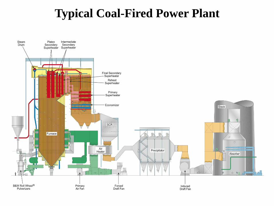
Typical Coal-Fired Power Plant

Pulverized Coal Combustion (PCC)
Terry F. Wall, Combustion processes for carbon capture, Proc. Comb. Inst., 31, 2007, 31.
- Oxidizing environment
- Mix of CO2 and N2
- ~ 12 mol. % CO2

Integrated Gasification Combined Cycle
(IGCC)
Terry F. Wall, Combustion processes for carbon capture, Proc. Comb. Inst., 31, 2007, 31.
- Reducing environment
- Mix of CO2 and H2
- ~ 40 mol. % CO2

Oxy-fuel Combustion
Terry F. Wall, Combustion processes for carbon capture, Proc. Comb. Inst., 31, 2007, 31.
Mostly CO2/H2O, easier separation
- Oxidizing environment
- Mix of CO2 and H2O
- high % CO2

Roadmap
• Concentration of CO2 in a given gas mixture dictates the energy required for
separation
• The energy required for separation only partially dictates the cost and
subsequent feasibility of a given separation process

Capture processes
Absorption Adsorption Membrane
Design parameters • Column height • Column width • # Columns
Solvent properties CO2 solubility Diffusion (CO2/base) Reaction kinetics
Design parameters • MTZ bed height • Column width • # Columns
Sorbent properties Pore size Capacity Phys/chem Diffusion
Work requirements • Pressure difference • Sorbent loading • Binding strength
Design parameters • Surface area • Thickness
Memb properties Solubility Diffusion Permeability Selectivity
Work requirements • Pressure difference • Compression • Stage cut
Work requirements • Gas Blowing • Solvent pumping • Heat of Regeneration
2nd law:
Thermodynamic minimum work
CO2 Gas Mixture
Traditional combustion (coal) NGCC IGCC Oxyfuel Direct air capture
Real work
% Capture % Purity
h =Wmin
Wreal Note: time scales (rates of mass transfer) are not represented in the work calculation

Minimum Work for Separation
combined first and second laws
Wmin = RT nBCO2 ln(yB
CO2 ) + nBB-CO2 ln(yB
B -CO2 )[ ] + RT nCCO2 ln(yC
CO2 ) + nCC -CO2 ln(yC
C -CO2 )[ ]
-RT nACO2 ln(yA
CO2 ) + nAA-CO2 ln(yA
A-CO2 )[ ]

Minimum Work for Separation

Sherwood Plot for Flue Gas Scrubbing
*Calculations carried out using IECM, all cases assume 500-MW plant burning Appalachian bituminous, NGCC (477-MW) O&M + annualized capital costs are included in the cost estimates

1Cost and Scale
Process Price [$/kg]
Concentration [mole fraction]
Emissions [kg/day]
Cost [1000s $/day]
CO2-PCC 0.045 0.121 8.59 x 10⁶ 392
CO2-NGCC 0.059 0.0373 3.01 x 10⁶ 178
SOx (MS) 0.66 0.00127 8.94 x 10⁴ 59.6
SOx (LS) 2.1 0.000399 (399 ppm)
2.32 x 10⁴ 50.4
NOx 1.1 0.000387 (387 ppm)
1.11 x 10⁴ 12.5
Hg 22000 5 x 10⁻⁹ (ppb) 0.951 21.6
1These can change based upon coal-type burned and scrubbing methods; 2EN Lightfoot, MCM Cockrem, What Are Dilute Solutions, Sep. Sci. Technol., 22(2), 165, 1987.
“the recovery of potentially valuable solutes from dilute solution is dominated by the costs of processing large masses of unwanted materials.”2 -Edwin Lightfoot

2nd-Law Efficiency Drops with Concentration
*Manuscript in preparation in collaboration w/ Kurt House, et al.

Second Law Efficiency
• The second law efficiency or the exergy (maximum work possible) efficiency is used to compare the efficiency of a real process to a corresponding ideal process
• The second law efficiency or the exergy efficiency (or effectiveness) is used to compare the efficiency of a cycle to a corresponding ideal cycle
h2nd =Wreal
Wideal
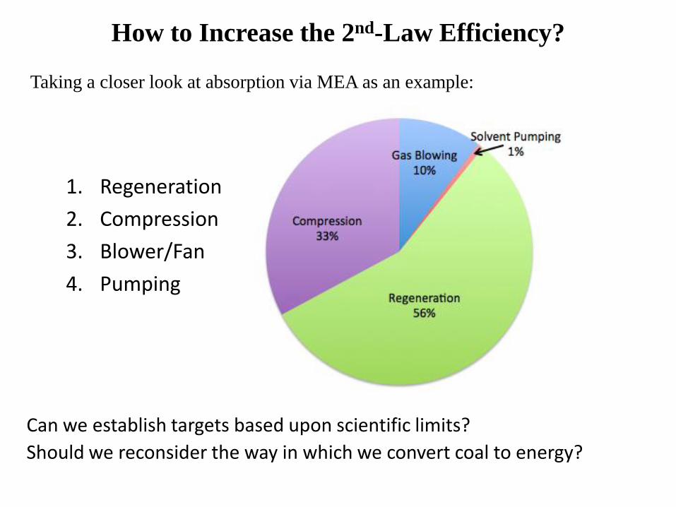
How to Increase the 2nd-Law Efficiency?
Taking a closer look at absorption via MEA as an example:
1. Regeneration
2. Compression
3. Blower/Fan
4. Pumping
Can we establish targets based upon scientific limits?
Should we reconsider the way in which we convert coal to energy?

Roadmap
• Operating vs Capital costs
• Where does minimum energy fit in?
• How should cost of CO2 captured be defined?

Capture processes
Absorption Adsorption Membrane
Design parameters • Column height • Column width • # Columns
Solvent properties CO2 solubility Diffusion (CO2/base) Reaction kinetics
Design parameters • MTZ bed height • Column width • # Columns
Sorbent properties Pore size Capacity Phys/chem Diffusion
Work requirements • Pressure difference • Sorbent loading • Binding strength
Design parameters • Surface area • Thickness
Memb properties Solubility Diffusion Permeability Selectivity
Work requirements • Pressure difference • Compression • Stage cut
Work requirements • Gas Blowing • Solvent pumping • Heat of Regeneration
2nd law:
Thermodynamic minimum work
CO2 Gas Mixture
Traditional combustion (coal) NGCC IGCC Oxyfuel Direct air capture
Real work
% Capture % Purity
h =Wmin
Wreal
Capital versus O&M
Capture processes
Absorption Adsorption Membrane
Design parameters • Column height • Column width • # Columns
Solvent properties CO2 solubility Diffusion (CO2/base) Reaction kinetics
Design parameters • MTZ bed height • Column width • # Columns
Sorbent properties Pore size Capacity Phys/chem Diffusion
Work requirements • Pressure difference • Sorbent loading • Binding strength
Design parameters • Surface area • Thickness
Memb properties Solubility Diffusion Permeability Selectivity
Work requirements • Pressure difference • Compression • Stage cut
Work requirements • Gas Blowing • Solvent pumping • Heat of Regeneration
2nd law:
Thermodynamic minimum work
CO2 Gas Mixture
Traditional combustion (coal) NGCC IGCC Oxyfuel Direct air capture
Real work
% Capture % Purity
h =Wmin
Wreal

Gas absorber using a solvent regenerated by stripping (a) Absorber, (b) Stripper

Components of Absorption

Mass Transfer of CO2 in Absorption
• Gas-phase CO2 diffusion
• CO2 concentration in the bulk gas is based upon the CO2 concentration in the
gas mixture
• CO2 dissolution at the gas-liquid interface
• CO2 concentration at the interface is determined by Henry’s Law
• Liquid-phase CO2 diffusion
• Simplifying assumption is that bulk liquid-phase CO2 concentration is zero
Later – Rate of Absorption and what this entails!
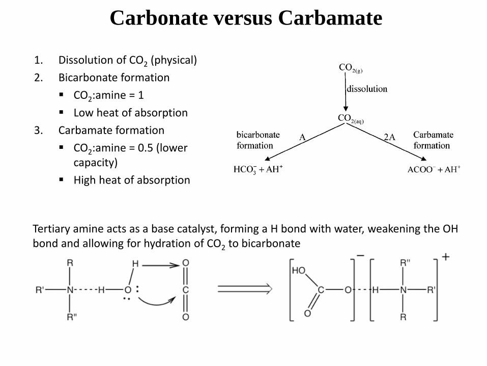
Carbonate versus Carbamate
Tertiary amine acts as a base catalyst, forming a H bond with water, weakening the OH bond and allowing for hydration of CO2 to bicarbonate
1. Dissolution of CO2 (physical)
2. Bicarbonate formation
CO2:amine = 1
Low heat of absorption
3. Carbamate formation
CO2:amine = 0.5 (lower capacity)
High heat of absorption

Special Case: Carbonic Anhydrase
• CA is a Zn-containing metalloenzyme
• Facilitates hydration and dehydration of CO2
• Rate of reaction is up to 8 orders of magnitude faster than CO2 binding in neutral water w/out catalyst
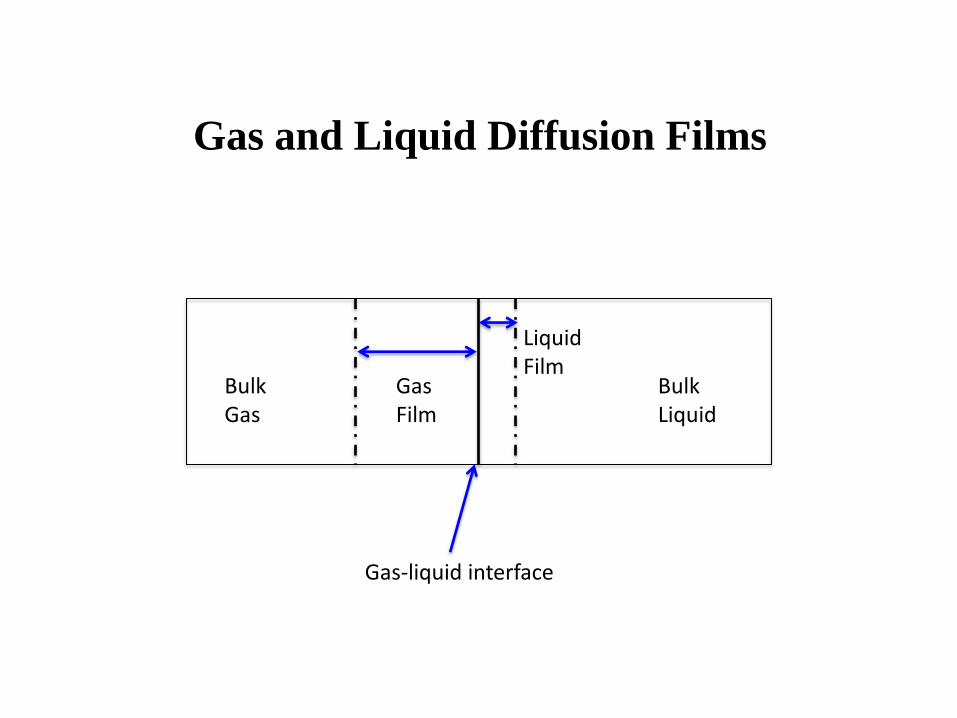
Gas and Liquid Diffusion Films
Gas-liquid interface
Bulk Gas
Bulk Liquid
Gas Film
Liquid Film

Rate of Absorption
• Gas-phase:
• Liquid-phase:
J is the overall flux including bulk and diffusive terms, δ is the film thickness (gas
or liquid), c∞ is the concentration of the bulk (gas or liquid), i represents the
interface, and k is the mass-transfer coefficient
JG,CO2= cCO2
G-DG,CO2
dcCO2
dzi
= cCO2G -
DG,CO2
dcG¥,CO2
- ci,CO2( )
= cCO2G - kG,CO2
cG¥,CO2- ci,CO2
( )
JL,CO2= cCO2
L -DL,CO2
dcCO2
dzi
= cCO2L -DL,CO2
dci,CO2
- cL¥,CO2( )
= cCO2L - kL,CO2
ci,CO2- cL¥,CO2
( )

Absorption (chemical)
• Irreversible 2nd-order Reaction:
– Assume that bulk CO2 concentration = 0 (i.e., c∞ = 0)
• Rate of Absorption = kLci,CO2E
• E = enhancement factor → factor by which absorption rate is increased by rxn
• Enhancement factor is a function of:
• Ei corresponds to instantaneous rxn
M =DCO2
k2cB
kL
CO2 +B k2¾ ®¾ CO2B
Ei =1+DBcB
2DCO2ci,CO2
and
Danckwerts, Gas-Liquid Reactions, 1970

Limiting Cases of the Film Model
In the case of the diffusion ratio between the base and CO2 in the liquid deviates from unity, the Higbie Model is preferred

Higbie Model
• Ei is calculated from:
Comparison of Model Absorption Rate Predictions for ↓HL; DR=2 Case
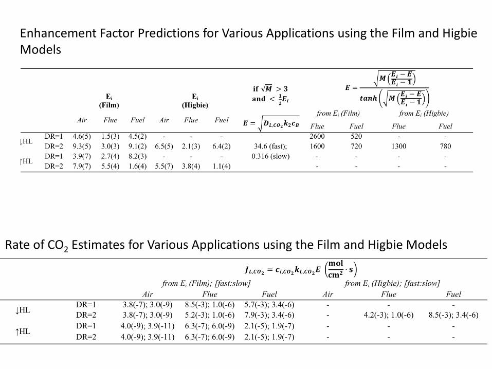
Rate of CO2 Estimates for Various Applications using the Film and Higbie Models
Enhancement Factor Predictions for Various Applications using the Film and Higbie Models

Potentially Tunable Parameters
†depending on the corrosive nature, typically less than 1.0 mol/L

Rate of Absorption
• Gas-phase:
• Liquid-phase:
These equations may be used to then determine the number and height of the
mass-transfer units to determine the design of the absorption (or stripping tower)
JG,CO2= cCO2
G-DG,CO2
dcCO2
dzi
= cCO2G -
DG,CO2
dcG¥,CO2
- ci,CO2( )
= cCO2G - kG,CO2
cG¥,CO2- ci,CO2
( )
JL,CO2= cCO2
L -DL,CO2
dcCO2
dzi
= cCO2L -DL,CO2
dci,CO2
- cL¥,CO2( )
= cCO2L - kL,CO2
ci,CO2- cL¥,CO2
( )

Real Work: Fan and Blower Power
• Fans and blowers:
– Fans operate near atm P w/ ΔP < 15 kPa
– Efficiency, ε, gas density, ρ, and pressure drop, ΔP, fan power is:
– Blowers handle 3 < ΔP < 500 kPa
– For adiabatic and reversible compression of an ideal gas, blowing power is:
T1 is the initial gas temperature, p1 and p2 are the
initial and final gas pressures, and k is the ratio of
specific heats (Appendix B of text)
– Efficiencies can range from 65 - 85%

Real Work: Solvent Pumping Power
• Pumps for solvent pumping:
– To cause liquid to flow work must be expended; a pump can assist in
overcoming pressure drop associated with solvent friction in a column and
can also assist in raising the solvent to a higher elevation
– Work is a function of the change in pressure and volumetric flow rate, Q:
– Intrinsic efficiencies, εi range from 40 to 85%, while drive efficiency, εd
can be approximated as 85%

Real Work: Heat of Regeneration
Heat required for regeneration:
• lean loading: 0.2 mol CO2/mol MEA
• rich loading: 0.4 mol CO2/mol MEA
• heat up solvent, e.g., heat capacity of 30 wt.% MEA w/ 0.4 mol bound CO2 =
3.418 J/g·K
• mass of solution = 0.4 mol CO2 + 7.9 mol H2O + 1 mol MEA
• 40 to 120 C is ~ 60.5 kJ to just heat up the water
• Additional 16.9 kJ/mol MEA to break the CO2 bond (~ 84 kJ/mol CO2)
• For regeneration of 0.2 mol CO2/1 mol MEA:
– (60.5 + 16.9) kJ/mol MEA x 1.0 mol MEA/0.2 mol CO2 = 387 kJ/mol CO2
– IECM (Rubin et al.) estimates ~ 39 kJ/mol; Rochelle estimates ~ 30 kJ/mol
• Why the gap?
– Heat exchange from the absorption process (water is an excellent heat transfer fluid)
– Heat exchange from multiple cycles

Real Work: Compression
• Compression of CO2 to 10 MPa is recommended for pipeline transport
• Adiabatic single-stage compression power can be calculated for an ideal gas
by:
Such that is the mass flow rate, T is the gas temperature, r is the compression
ratio, i.e., p2/p1, k is the ratio of heat capacities (i.e., Cv/Cp), and M is the molecular
weight of the gas
• Compression of CO2 from 1 atm (0.101 MPa) to 10 Mpa ~ 20 kJ/mol CO2
• Rochelle et al. report significantly lower compression (~ 10 kJ/mol CO2)
requirements due to novel stripping schemes that incorporate gas compression
within the process
• IECM (Rubin et al.) report compression work ~ 23 kJ/mol CO2
m

Real Work – Total
• Total real work required for CO2 capture includes:
– Wfan + Wpump + Wregen + Wcomp
• On average, estimates for an amine-based absorption process (from IECM)
– Wfan ~ 7 kJ/mol CO2
– Wpump ~ 0.5 kJ/mol CO2
– Wregen ~ 39 kJ/mol CO2
– Wcomp ~ 23 kJ/mol CO2 [1 atm → 10 MPa]

Capture processes
Absorption Adsorption Membrane
Design parameters • Column height • Column width • # Columns
Solvent properties CO2 solubility Diffusion (CO2/base) Reaction kinetics
Design parameters • MTZ bed height • Column width • # Columns
Sorbent properties Pore size Capacity Phys/chem Diffusion
Work requirements • Pressure difference • Sorbent loading • Binding strength
Design parameters • Surface area • Thickness
Memb properties Solubility Diffusion Permeability Selectivity
Work requirements • Pressure difference • Compression • Stage cut
Work requirements • Gas Blowing • Solvent pumping • Heat of Regeneration
2nd law:
Thermodynamic minimum work
CO2 Gas Mixture
Traditional combustion (coal) NGCC IGCC Oxyfuel Direct air capture
Real work
% Capture % Purity
h =Wmin
Wreal

Outline of Adsorption Processes

Physisorption versus Chemisorption
• When CO2 is held loosely via weak intermolecular forces it’s termed
physisorption, heat of adsorption ~ 10 – 15 kcal/mol
• When CO2 is held via covalent bonds it’s termed chemisorption
• Most CO2 adsorption mechanisms are physisorption due to the need for low
heats of adsorption
• Heats of adsorption of zeolites and MOFs can actually be quite high (e.g., ~ 50
kcal/mol)
• Common sorbents: activated carbon, zeolites, MOFs, etc.

Zeolite Properties
• Silicon and aluminum atom structures tetrahedrally bonded with oxygen
• Aluminum typically exists in a 3+ oxidation state, so will have a charge of -1 when tetrahedrally bonded
• Cations (positive charges) are used to stabilize these charges, distributing themselves in a way to minimize the free energy of the system
• How do zeolites work to separate N2 from O2 or CO2 from N2?
– They actually prefer to adsorb N2
– The interaction energy bet/ ions and N2 are much stronger than ions and O2
• O2-Na+ (20 kJ/mol); N2-Na+ (36 kJ/mol)
• O2-Li+ (32 kJ/mol); N2-Li+ (51 kJ/mol)
– N2 has a higher quadrupole moment than O2
– Adsorption is dependent upon the interaction energy bet/ an adsorbate and a cation of a zeolite and includes contributions from van der waals and electrostatic interactions; electrostatic energies include induced dipoles, permanent dipoles and quadrupoles

Kinetic and Electrostatic Properties of Gases

Zeolite Framework

MOF Framework
Zn4(O)O12C6 cluster organic linker 8 clusters comprise the 18.5 Å diameter
(b) And (c) show MOF structural features

Hollow-fiber Sorbents

Adsorption Cycles

Pressure Drop
• Ergun verified this eqn. for a variety of different shapes of packing material
with varying packing densities; the first void space term accounts for the
viscous loss component and the second for the KE loss component
• It is important to note that a small change in ε results in a large change in
∆P
• Typical numbers for calculations:
– Void fractions for spheres, cylinders, and granular packings typically range
from 0.3-0.6
– Sphericity ranges from 0.6-0.95
3
2
0
3
2
22
0 175.1)1(150
psps D
V
D
V
L
P

Real Work: Overcoming Pressure Drop
• How much blower power is required to overcome the pressure drop in an
adsorption system of a packed tower?
• P is power in kilowatts, P1 is the inlet pressure, P2 is outlet pressure, V1 is
the flow rate of gas, k is the ratio of specific heat (k=Cp/Cv, where Cp and
Cv are the heat capacity at constant pressure and volume, respectively)
– Typical values for k = 1.4 for air
11
/)1(
1
211
kk
P
P
k
kVPPower

Capture processes
Absorption Adsorption Membrane
Design parameters • Column height • Column width • # Columns
Solvent properties CO2 solubility Diffusion (CO2/base) Reaction kinetics
Design parameters • MTZ bed height • Column width • # Columns
Sorbent properties Pore size Capacity Phys/chem Diffusion
Work requirements • Pressure difference • Sorbent loading • Binding strength
Design parameters • Surface area • Thickness
Memb properties Solubility Diffusion Permeability Selectivity
Work requirements • Pressure difference • Compression • Stage cut
Work requirements • Gas Blowing • Solvent pumping • Heat of Regeneration
2nd law:
Thermodynamic minimum work
CO2 Gas Mixture
Traditional combustion (coal) NGCC IGCC Oxyfuel Direct air capture
Real work
% Capture % Purity
h =Wmin
Wreal

Outline of Membrane Processes

Membrane Separation Mechanisms

Gradients and Terminology
Important Terms: Stage cut = permeate flow rate/feed flow rate Permeate/Residue Concentrations Pressure Ratio = permeate pressure/feed pressure

Permeability vs. Permeance
• Permeability vs Permeance
• J = flux; D = diffusivity, S = solubility, z = membrane thickness, and
coefficient of pressure difference is the permeance
• Permeability is the product of diffusivity and solubility and is a property of the
material
• Typical units of permeance are GPUs or standard ft3/ft2 h atm
• Permeance is a property of a particular membrane
• Typical units of permeability are Barrers

Selectivity
• Selectivity may be in terms of permeability, diffusivity, or solubility
• In 1991, Lloyd M. Robeson quantified the trade-off between permeability and
selectivity; displayed in terms of Robeson plots

Robeson Plots

Gas Separation Process Design
• CO2 capture from
natural gas
• Residue is
purified CH4 w/
permeate stream
enriched in CO2
• Note high feed
and residue
streams
Source: Richard Baker, Membrane Technology and Applications

Short-Cut Design Calculation
• Short-cut area calculation described by Hogsett and Mazur, Hydrocarbon
Processing, 62, 52 (1983)
• Using values from the previous slide and a CO2 permeance of 5.5 ft3 (STP)/(ft2
100 psi hr), results in a membrane area of 31,500 ft2
Area =x1permQperm
P1
lp feedxlog-mean - ppermx1perm( )
@permeate flow rate of 1
flux of species1
where Q is volumetric flowrate, x is mole fraction, p is pressure
P1
lis permeance of species1
xlog-mean =x1 feed - x1residue
lnx1 feed
x1residue
æ
èç
ö
ø÷

Local Permeate Concentration
Selectivity and pressure ratio effects on the local permeate concentration

Capture processes
Absorption Adsorption Membrane
Design parameters • Column height • Column width • # Columns
Solvent properties CO2 solubility Diffusion (CO2/base) Reaction kinetics
Design parameters • MTZ bed height • Column width • # Columns
Sorbent properties Pore size Capacity Phys/chem Diffusion
Work requirements • Pressure difference • Sorbent loading • Binding strength
Design parameters • Surface area • Thickness
Memb properties Solubility Diffusion Permeability Selectivity
Work requirements • Pressure difference • Compression • Stage cut
Work requirements • Gas Blowing • Solvent pumping • Heat of Regeneration
2nd law:
Thermodynamic minimum work
CO2 Gas Mixture
Traditional combustion (coal) NGCC IGCC Oxyfuel Direct air capture
Real work
% Capture % Purity
h =Wmin
Wreal

Additional Slides

Absorption-Related Mass-Transfer Correlations

Choosing an Appropriate Solvent
• high CO2 capacity
• fast kinetics with CO2
• low volatility
• low viscosity
• nontoxic, nonflammable, and noncorrosive
• high thermal stability
• resistance to oxidation
• Examples include amines, carbonates, and ammonia

Common Types of Sorbents

Influence of Pressure Ratio
• Original Case:
– 100 MSCFH natural gas
– Feed pressure = 480 psia
– Permeate pressure = 20 psia
– ΔP = 460 psia
– Pressure ratio, γ = 0.042
– Feed CO2 = 12%
– Product CO2 = 2%
– Area required = 1,700 ft2
• New Case:
– 100 MSCFH natural gas
– Feed pressure = 1200 psia
– Permeate pressure = 200 psia
– ΔP = 1000 psia
– Pressure ratio, γ = 0.17
– Feed CO2 = 12%
– Product CO2 = 2%
– Area required = 7,800 ft2

Multi-Stage Processes