ENERGY HARVESTING TRANSDUCERS - PIEZOELECTRIC · most common piezoelectric materials for energy...
47
ENERGY HARVESTING TRANSDUCERS - PIEZOELECTRIC (ICT-ENERGY SUMMER SCHOOL 2016) Shad Roundy, PhD Department of Mechanical Engineering University of Utah [email protected]
Transcript of ENERGY HARVESTING TRANSDUCERS - PIEZOELECTRIC · most common piezoelectric materials for energy...
ENERGY HARVESTING TRANSDUCERS - PIEZOELECTRIC
(ICT-ENERGY SUMMER SCHOOL 2016)
Shad Roundy, PhD
Department of Mechanical Engineering
University of Utah

Three Types of Electromechanical Lossless Transduction
1. Electrodynamic (also called electromagnetic or inductive): motor/generator action is produced by the current in, or the motion of an electric conductor located in a fixed transverse magnetic field (e.g. voice coil speaker)
2. Piezoeletric: motor/generator action is produced by the direct and converse piezoelectric effect – dielectric polarization gives rise to elastic strain and vice versa (e.g. tweeter speaker)
3. Electrostatic: motor/generator action is produced by variations of the mechanical stress by maintaining a potential difference between two or more electrodes, one of which moves (e.g. condenser microphone)
Credit: This classification and much of the flow from Electromagnetic section is based on the 2013 PowerMEMS presentation by Prof. David Arnold at the University of Florida

Outline for Short Course
• Introduction and Linear Energy Harvesting
• Energy Harvesting Transducers
– Electromagnetic
– Piezoelectric
– Electrostatic
• Wideband and Nonlinear Energy Harvesting
• Applications
Outline
• Fundamental equations of piezoelectricity
• Piezoelectric energy harvesting (without dynamics)
• Survey of materials
• Dynamics of vibration energy harvesting
• Current research and examples
Piezoelectricity
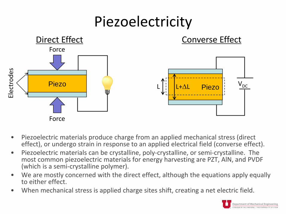
• Piezoelectric materials produce charge from an applied mechanical stress (direct effect), or undergo strain in response to an applied electrical field (converse effect).
• Piezoelectric materials can be crystalline, poly-crystalline, or semi-crystalline. The most common piezoelectric materials for energy harvesting are PZT, AlN, and PVDF (which is a semi-crystalline polymer).
• We are mostly concerned with the direct effect, although the equations apply equally to either effect.
• When mechanical stress is applied charge sites shift, creating a net electric field.
Piezo
Elec
tro
des
Force
Force
PiezoVDCL L+DL
Direct Effect Converse Effect

Piezoelectricity
• Crystal structure does not have a center of symmetry.• Under no mechanical force, the system is under equilibrium.• If material is subjected to mechanical stress or strain, the crystalline
structure is deformed, the distance between the charge centers changes.
• In order to keep electrical neutrality, charges appear at the surface of the crystal.
Positive and negative charge center
Positive and negative charges
Strain
Adapted from Briand, et. al. 2015

Fundamental Equations
• Note, without the piezoelectric strain coefficient we just have Hooke’s law and the equation for a dielectric material.
• The “d” coefficient relates strain to electric field (strain coefficient) and charge to stress (charge coefficient).
𝑆 = 𝑠𝐸 𝑇 + 𝑑𝑡 𝐸
𝐷 = 𝑑 𝑇 + 𝜖𝑇 {𝐸}
StrainCompliance
Stress
Electricaldisplacement
Piezoelectricstrain coefficient
PermittivityElectric field
[ ]E – constant electric field(short circuit)
[ ]D – constant charge(open circuit)
[ ]T – constant stress (free condition)
[ ]S – constant strain(clamped condition)

Fundamental Equations
• 4, 5, 6 are the shear stress and strain directions.• 3 is generally the direction of electrical poling• In most actual situations, these are reduced to scalar equations due to
geometric and constraints and placement of electrodes.
3
2
1
15
24
33
32
31
6
5
4
3
2
1
66
55
44
333231
232221
131211
6
5
4
3
2
1
000
00
00
00
00
00
00000
00000
00000
000
000
000
E
E
E
d
d
d
d
d
T
T
T
T
T
T
s
s
s
sss
sss
sss
S
S
S
S
S
S
E
E
E
EEE
EEE
EEE
3
2
1
33
22
11
6
5
4
3
2
1
333231
24
15
3
2
1
00
00
00
000
00000
00000
E
E
E
T
T
T
T
T
T
ddd
d
d
D
D
D
3
1
2
44
6 6
5
5
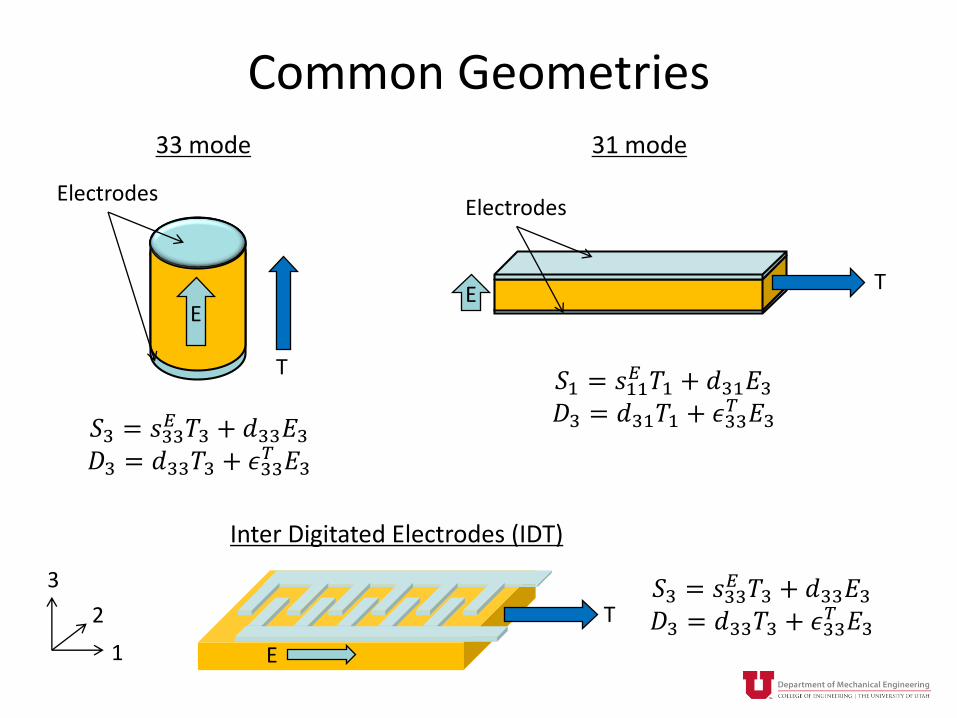
Common Geometries
1
2
3
T
Electrodes
E
𝑆3 = 𝑠33𝐸 𝑇3 + 𝑑33𝐸3
𝐷3 = 𝑑33𝑇3 + 𝜖33𝑇 𝐸3
ET
𝑆1 = 𝑠11𝐸 𝑇1 + 𝑑31𝐸3
𝐷3 = 𝑑31𝑇1 + 𝜖33𝑇 𝐸3
Electrodes
T𝑆3 = 𝑠33
𝐸 𝑇3 + 𝑑33𝐸3𝐷3 = 𝑑33𝑇3 + 𝜖33
𝑇 𝐸3E
33 mode 31 mode
Inter Digitated Electrodes (IDT)

Alternate Forms of the Equations
𝑇 = 𝑐𝐸𝑆 − 𝑒𝐸𝐷 = 𝑒𝑆 + 𝜖𝑆𝐸
Note: Subscripts have been dropped here for simplicity.
𝑐 = 1/𝑠 = stiffness
𝑒 =𝛿𝐷
𝛿𝑆
𝐸= −
𝛿𝑇
𝛿𝐸
𝑆= stress coefficient
𝑆 = 𝑠𝐷𝑇 + 𝑔𝐷𝐸 = −𝑔𝑇 + 𝛽𝑇𝐷
𝛽 = 𝜖−1
𝑔 = −𝛿𝐸
𝛿T
𝐷=
𝛿𝑆
𝛿𝐷
𝑇= voltage coefficient
𝑇 = 𝑐𝐷𝑆 − ℎ𝐷𝐸 = −ℎ𝑆 + 𝛽𝑇𝐷
ℎ = −𝛿𝐸
𝛿𝑆
𝐷
= −𝛿𝑇
𝛿𝐷
𝑆
Piezoelectric Coupling Coefficient
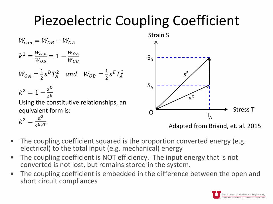
• The coupling coefficient squared is the proportion converted energy (e.g. electrical) to the total input (e.g. mechanical) energy
• The coupling coefficient is NOT efficiency. The input energy that is not converted is not lost, but remains stored in the system.
• The coupling coefficient is embedded in the difference between the open and short circuit compliances
𝑊𝑐𝑜𝑛 = 𝑊𝑂𝐵 −𝑊𝑂𝐴
𝑘2 =𝑊𝑐𝑜𝑛
𝑊𝑂𝐵= 1 −
𝑊𝑂𝐴
𝑊𝑂𝐵
𝑊𝑂𝐴 =1
2𝑠𝐷𝑇𝐴
2 𝑎𝑛𝑑 𝑊𝑂𝐵 =1
2𝑠𝐸𝑇𝐴
2
𝑘2 = 1 −𝑠𝐷
𝑠𝐸
Using the constitutive relationships, an equivalent form is:
𝑘2 =𝑑2
𝑠𝐸𝜖𝑇
Stress T
Strain S
SA
SB
TAO
sD
sE
Adapted from Briand, et. al. 2015

Some Relationships Between Coefficients
𝑑 𝑘 𝑔 𝑒
𝑑
𝑆𝑡𝑟𝑎𝑖𝑛 𝐷𝑒𝑣𝑒𝑙𝑜𝑝𝑒𝑑
𝐴𝑝𝑝𝑙𝑖𝑒𝑑 𝐸𝑙𝑒𝑐𝑡𝑟𝑖𝑐 𝐹𝑖𝑒𝑙𝑑
𝑆ℎ𝑜𝑟𝑡 𝐶𝑖𝑟𝑐𝑢𝑖𝑡 𝐶ℎ𝑎𝑟𝑔𝑒 𝐷𝑒𝑛𝑠𝑖𝑡𝑦
𝐴𝑝𝑝𝑙𝑖𝑒𝑑 𝑆𝑡𝑟𝑒𝑠𝑠
𝑑31 = 𝑘31 𝑠11𝐸 휀33
𝑇
𝑑33 = 𝑘33 𝑠33𝐸 휀33
𝑇
𝑑31 = 𝑔31휀33𝑇
𝑑33 = 𝑔33휀33𝑇
𝑑33 =𝑒33𝑌33
𝑘
𝑘31 =𝑑31
𝑠11𝐸 휀33
𝑇
𝑘33 =𝑑33
𝑠33𝐸 휀33
𝑇
𝑀𝑒𝑐ℎ𝑎𝑛𝑖𝑐𝑎𝑙 𝐶𝑜𝑛𝑣𝑒𝑟𝑡𝑒𝑑 𝑡𝑜 𝐸𝑙𝑒𝑐𝑟𝑖𝑐𝑎𝑙 𝐸𝑛𝑒𝑟𝑔𝑦
𝑀𝑒𝑐ℎ𝑎𝑛𝑖𝑐𝑎𝑙 𝐸𝑛𝑒𝑟𝑔𝑦 𝐼𝑛𝑝𝑢𝑡
1/2
𝐸𝑙𝑒𝑐𝑡𝑟𝑖𝑐𝑎𝑙 𝐶𝑜𝑛𝑣𝑒𝑟𝑡𝑒𝑑 𝑡𝑜 𝑀𝑒𝑐ℎ𝑎𝑛𝑖𝑐𝑎𝑙 𝐸𝑛𝑒𝑟𝑔𝑦
𝐸𝑙𝑒𝑐𝑡𝑟𝑖𝑐𝑎𝑙 𝐸𝑛𝑒𝑟𝑔𝑦 𝐼𝑛𝑝𝑢𝑡
1/2
𝑘31 = 𝑔31휀33𝑇
𝑠11𝐸
𝑘33 = 𝑔33휀33𝑇
𝑠33𝐸
𝑔
𝑔31 =𝑑31
휀33𝑇
𝑔33 =𝑑33
휀33𝑇
𝑔31 = 𝑘31𝑠11𝐸
휀33𝑇
𝑔33 = 𝑘33𝑠33𝐸
휀33𝑇
𝑂𝑝𝑒𝑛 𝐶𝑖𝑟𝑐𝑢𝑖𝑡 𝐸𝑙𝑒𝑐𝑡𝑟𝑖𝑐 𝐹𝑖𝑒𝑙𝑑
𝐴𝑝𝑝𝑙𝑖𝑒𝑑 𝑆𝑡𝑟𝑒𝑠𝑠
𝑆𝑡𝑟𝑎𝑖𝑛 𝐷𝑒𝑣𝑒𝑙𝑜𝑝𝑒𝑑
𝐴𝑝𝑝𝑙𝑖𝑒𝑑 𝐶ℎ𝑎𝑟𝑔𝑒 𝐷𝑒𝑛𝑠𝑖𝑡𝑦

Cantilever Beam – 31 Coupling
• Although 31 coefficients are generally lower, bending structures are often used because of the ability to produce lower frequency oscillators and generate higher strains
2
1
3

Common Energy Harvesting Structures
Elvin and Erturk, Advances in Energy Harvesting Methods, 2013
http://www.morpheus.umd.edu/research/systems/piex-flex-actuators.html
Flextensional Device

Outline
• Fundamental equations of piezoelectricity
• Piezoelectric energy harvesting (without dynamics)
• Survey of materials
• Dynamics of vibration energy harvesting
• Current research and examples
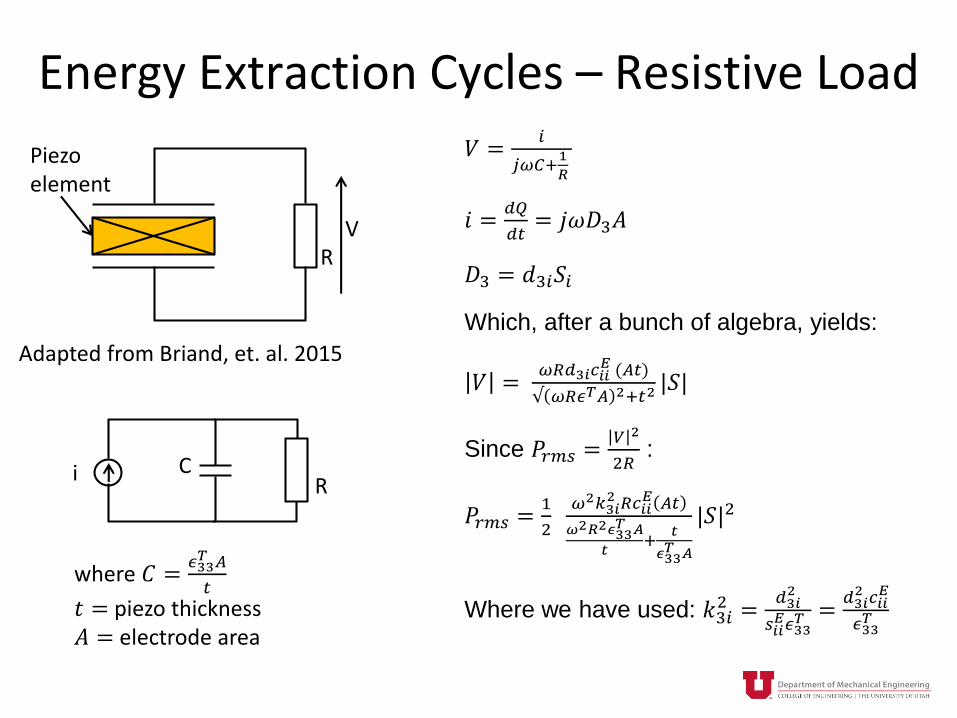
Energy Extraction Cycles – Resistive Load
RV
Piezo element
Adapted from Briand, et. al. 2015
𝑉 =𝑖
𝑗𝜔𝐶+1
𝑅
𝑖 =𝑑𝑄
𝑑𝑡= 𝑗𝜔𝐷3𝐴
𝐷3 = 𝑑3𝑖𝑆𝑖
Which, after a bunch of algebra, yields:
𝑉 =𝜔𝑅𝑑3𝑖𝑐𝑖𝑖
𝐸 (𝐴𝑡)
√ 𝜔𝑅𝜖𝑇𝐴 2+𝑡2|𝑆|
Since 𝑃𝑟𝑚𝑠 =𝑉 2
2𝑅:
𝑃𝑟𝑚𝑠 =1
2
𝜔2𝑘3𝑖2 𝑅𝑐𝑖𝑖
𝐸 𝐴𝑡
𝜔2𝑅2𝜖33𝑇 𝐴
𝑡+
𝑡
𝜖33𝑇 𝐴
|𝑆|2
Where we have used: 𝑘3𝑖2 =
𝑑3𝑖2
𝑠𝑖𝑖𝐸𝜖33
𝑇 =𝑑3𝑖2 𝑐𝑖𝑖
𝐸
𝜖33𝑇
RCi
where 𝐶 =𝜖33𝑇 𝐴
𝑡
𝑡 = piezo thickness𝐴 = electrode area

Energy Extraction Cycles – Resistive Load
RV
Piezo element
Adapted from Briand, et. al. 2015
If we differentiate the previous expression
with respect to R, we find that:
𝑅𝑜𝑝𝑡 =𝑡
𝜔𝜖33𝑇 𝐴
=1
𝜔C
Substituting in:
𝑃𝑟𝑚𝑠 =𝜔
4𝑘3𝑖2 𝑐𝑖𝑖
𝐸 𝐴𝑡 𝑆𝑖2
𝐸𝑐𝑦𝑐 =𝜋
2𝑘3𝑖2 𝑐𝑖𝑖
𝐸 𝐴𝑡 𝑆𝑖2
Then the material figure of merit (FOM) is:
𝐹𝑂𝑀 = 𝑘3𝑖2 𝑐𝑖𝑖
𝐸 =𝑑3𝑖2 𝑐𝑖𝑖
𝐸2
𝜖33𝑇 =
𝑒3𝑖2
𝜖33𝑇
RCi
Where 𝐶 =𝜖33𝑇 𝐴
𝑡
𝑡 = piezo thickness𝐴 = electrode area

Increasing Power Output
• Increase the strain level of the piezoelectric material• Improve material Figure of Merit• Increase volume of material under strain (i.e. thicker
piezoelectric films)• Increase frequency
– Note usually you have no control over the excitation frequency– In quasi-static applications, increasing frequency can result in more power
output– In base driven vibration applications, frequency up conversion may have
practical benefits, but won’t fundamentally result in high power output
• Improve energy extraction circuits
• There is ongoing research addressing each of these issues
𝑃𝑟𝑚𝑠 =𝜔
4𝑘3𝑖2 𝑐𝑖𝑖
𝐸 𝐴𝑡 𝑆𝑖2

Outline
• Fundamental equations of piezoelectricity
• Piezoelectric energy harvesting (without dynamics)
• Survey of materials
• Dynamics of vibration energy harvesting
• Current research and examples

Perovskites
• Best performing piezoelectric materials so far
• Exhibit ABO3 structure
• Ferroelectric – must be poled and lose piezoelectricity above the Curie temperature
• Best materials contain lead
Pb(Zr,Ti)O3 (PZT) BaTiO3 (BTO) Pb(Mg,Nb)O3-PbTiO3 (PMN-PT)Single CrystalTRS Ceramics

Perovskites – Material Comparison
• Bulk material properties
• Thinfilms are generally lower
Material d
(10-12 m/V)
c
(109 N/m2)
rel k FOM (d2c2/rel)
PZT-5A1 d33 = 390
d31 = -190
cE11= 66
cE33= 52
1800 k33 = 0.72
k31 = 0.35
FOM33=0.23
FOM31=0.09
PZT-5H1 d33 = 650
d31 = -320
cE11= 62
cE33= 50
3800 k33 = 0.75
k31 = 0.44
FOM33=0.28
FOM31=0.10
PMN-PT2 d33 = 2820
d31 = -1330
cE11= 11.5
cE33= 10
8200 FOM33=0.10
FOM31=0.028
PMN-
32PT3
d33 = 2000
d31 = -920
cE11= 20
cE33= 20
4950 k33 = 0.95
k31 = 0.78
FOM33=0.32
FOM31=0.07
1 www.piezo.com2 Cao et. al. J. Appl. Phys. Vol. 96, No. 1, 20043 Briand et. al. 2015

Advances In Thinfilm PZT
• Susan Trolier-McKinstry’s group at Penn State has developed very high quality PZT thinfilms fabricated on nickel or silicon substrates
PZT(3μm)
Ni(~25μm)
HfO2
LaNiO
3
HfO2LaNiO
3
PZT(3μm)
Upper
Lower
~3 μm

Advances In Thinfilm PZT
0.0
0.2
0.4
0.6
0.8
1.0
1.2
0% 20% 40% 60% 80% 100%
FoM
C
2/m
4
f001
Yeager, Funakubo, Trolier-McKinstry
et al., JAP, 2012
Current
state of the
art
S. H. Baek et. al., Science 2011

Wurtzites
• Exhibit permanent polarization– Can operate to very high temperatures
– Do not need to be poled
• Wide range of material properties from different groups producing thinfilms
Aluminum Nitride (AlN) Zinc Oxide (ZnO)

AlN – Material Comparison
• All thinfilm properties
Material d
(10-12 m/V)
c
(109 N/m2)
rel k FOM (d2c2/rel)
AlN1 d33 = 5
d31 = -2.5
cE11= 300
cE33= 300
10 k33 = 0.07 FOM33=0.23
FOM31=0.06
AlN2 d31 = -147 cE11= 395
cE33= 395
9.5 k31 = 0.1 FOM31 =0.035
AlN3 FOM31 =0.1
1 Defay, Integration of Ferroelectric and Piezoelectric Thinfilms (2011)2 Lin et. al. J. Advanced Materials (2012)3 Andosca et al., Sensors and Actuators A, 178 (2012) 76

Harsh Environment Applications
• Material is non-ferroelectric
• Maintains piezoelectric properties up to at least several hundred degrees C
High temperature Energy HarvestersLai et. al. Transducers 2013
High temperature GHz ResonatorLi et. al., Adv. Mater. 2012, 24, 2722-2727
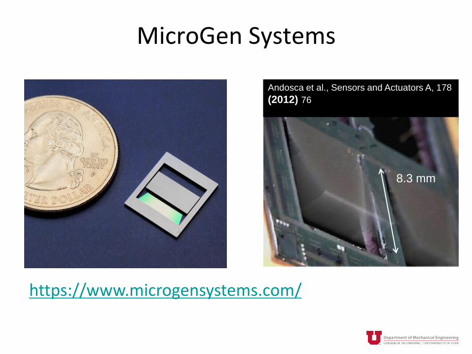
MicroGen Systems
Andosca et al., Sensors and Actuators A, 178
(2012) 76
8.3 mm
https://www.microgensystems.com/

PVDF
• Very poor material figure of merit
• Useful because of cost, flexibility, and robustness
Measurement Specialties Inc.
Paradiso and Starner, IEEE Pervasive Computing, 2005.
Material d
(10-12 m/V)
c
(109 N/m2)
rel k FOM (d2c2/rel)
PVDF1 d33 = -30
d31 = 22
cE11= 8.3
cE33= 8.3
10 FOM33=0.006
FOM31=0.003

Other Notes
• Concern over the lead in PZT has led to development of other lead-free piezoelectric materials such as (K,Na)NbO3 (KNN)
• For MEMS devices, PZT is commonly fabricated with either a sol-gel process or by sputtering
– Max thickness is generally 2 um or less
• AlN is usually fabricated by sputtering
– Max thickness is generally 2 um or less
– Multi-user AlN process form MEMSCAP (PiezoMUMPs) http://www.memscap.com/products/mumps/piezomumps

Outline
• Fundamental equations of piezoelectricity
• Piezoelectric energy harvesting (without dynamics)
• Survey of materials
• Dynamics of vibration energy harvesting
• Current research and examples

Vibration Energy Harvesters (VEHs)
m: y(t)
Ground: A(t)
z(t)
kbR
i
feA(t)
• Piezoelectric bimorph beam VEH• Base (or wall) is driven by vibration
with acceleration A(t)• There is a proof mass at the end of
the beam, which flexes causing a 3-1 mode piezoelectric transducer
• Lumped parameter model of the piezoelectric beam VEH
• Mass is the equivalent mass (actual mass and inertial effects of beams)
• Piezo element creates an electrically induced force (fe) on the mechanical oscillator as well as generating current through a load circuit
Roundy & Wright, SMS, 2004

VDRG Vibration Energy Harvester Model
Mitcheson et. al., JMEMS 2004Halvorsen et. al. J. Phys. Conf. Series, 2013Heit & Roundy, En. Harv. and Sys., 2015
m: y(t)
Ground: A(t)
z(t)
kbm
be
• be is the electrically induced damping coefficient
• Power dissipated through be is the power extracted by the load circuit
• This model has been shown to produce the upper bound on extractable power from in input dominated by a single, stable frequency
𝑍 𝑗𝜔 =1
1−𝑟2 +𝑗2𝜁𝑟
𝐴
𝜔𝑛2 where 𝑟 =
𝜔
𝜔𝑛
𝑍 𝑗𝜔 =1
1−𝑟2 2+ 2𝜁𝑟 212
𝐴
𝜔𝑛2
𝑃𝑟𝑚𝑠 =1
2𝑏𝑒𝜔
2 𝑍 𝑗𝜔 2
𝑃𝑟𝑚𝑠 =𝑚𝜁𝑒𝑟
3𝐴2
𝜔 1−𝑟2 2+ 2𝜁𝑟 2
where 휁𝑒 =𝑏𝑒
2𝑚𝜔𝑛and 휁 = 휁𝑒 + 휁𝑚

Adding the Electrical States
m: y(t)
Ground: A(t)
z(t)
kbR
i
fe
-mA(t)
m b
C
a:1 V
1/k
Rሶ𝑧
+
-fe

Adding the Electrical States
Governing Equations𝑚 ሷ𝑧 + 𝑏 ሶ𝑧 + 𝑘𝑧 + 𝛼𝑉 = −𝑚𝐴
𝐶 ሶ𝑉 +1
𝑅𝑉 = 𝛼 ሶ𝑧
where 𝛼 is the electromechanical force factor
Note, this is a three state system: 𝑧, ሶ𝑧, 𝑉
Power Output
𝑃𝑟𝑚𝑠 =1
2
𝑉 2
𝑅
-mA(t)
m b
C
a:1 V
1/k
Rሶ𝑧
+
-fe

Force Factor a (Cantilever Bimorph)Transformer Equations𝑓𝑒 = 𝛼𝑉𝑖 = 𝛼 ሶ𝑧
From piezo relationships
𝑆1 = 𝑠1𝐸𝑇1 + 𝑑31𝐸3
Assuming a clamped condition:
𝑇1 = −𝑐1𝐸𝑑31𝐸3
Get relationship between fe and V𝑉 = 𝐸3𝑡
t is the piezo thickness
𝑓𝑒 =2𝑤𝑡2
3𝑙𝑇1 from beam mechanics
𝑓𝑒 = −2𝑤𝑡𝑐1
𝐸𝑑31
3𝑙𝑉
𝛼 = −2𝑤𝑡𝑐1
𝐸𝑑31
3𝑙
-mA(t)
m b
C
a:1 V
1/k
R
+
-fe
w
l
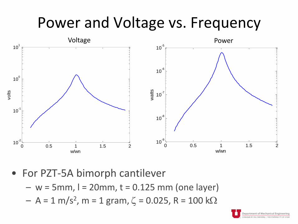
Power and Voltage vs. Frequency
• For PZT-5A bimorph cantilever– w = 5mm, l = 20mm, t = 0.125 mm (one layer)
– A = 1 m/s2, m = 1 gram, z = 0.025, R = 100 kW
0 0.5 1 1.5 210
-2
10-1
100
101
w/wn
vo
lts
0 0.5 1 1.5 210
-9
10-8
10-7
10-6
10-5
w/wnw
atts
Voltage Power
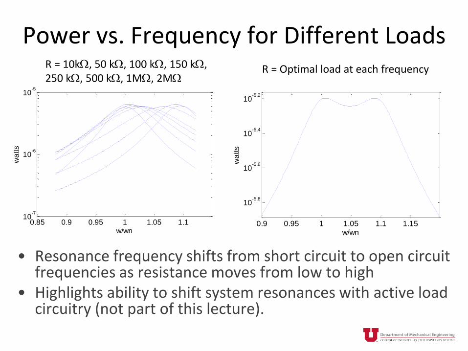
Power vs. Frequency for Different Loads
• Resonance frequency shifts from short circuit to open circuit frequencies as resistance moves from low to high
• Highlights ability to shift system resonances with active load circuitry (not part of this lecture).
0.85 0.9 0.95 1 1.05 1.110
-7
10-6
10-5
w/wn
wa
tts
R = 10kW, 50 kW, 100 kW, 150 kW, 250 kW, 500 kW, 1MW, 2MW
0.9 0.95 1 1.05 1.1 1.15
10-5.8
10-5.6
10-5.4
10-5.2
w/wnw
atts
R = Optimal load at each frequency

Phase Relationship Between Voltage and Velocity
• If piezoelectric coupling could accurately be modeled by a simple viscous damper, voltage and velocity would be exactly in phase as power would be proportional to velocity squared
0 0.5 1 1.5 2-300
-250
-200
-150
-100
-50
w/wn
de
g
V
zDot
1/RC >> wn
0 0.5 1 1.5 2-350
-300
-250
-200
-150
-100
-50
w/wnd
eg
V
zDot
1/RC = wnV lags by about 45
0 0.5 1 1.5 2-400
-350
-300
-250
-200
-150
-100
-50
w/wn
de
g
V
zDot
1/RC << wnV lags by about 90

Power vs.Load Resistance
• Taken at w = wn
• There is another optimal load resistance at w > wn
• It’s better to miss on the high side of the effective load resistance than on the low side
0 0.5 1 1.5 2
x 105
2
3
4
5
6
7x 10
-6
Ohms
wa
tts

Piezoelectric Figure of Merit and Damping
• Resonance is assumed• For resonant systems, better piezoelectric materials may not make a large difference• More coupling results in lower displacement (i.e. more damping)• Once the proof mass displacement is limited by the electromechanical coupling as
opposed to mechanical damping, better material no longer helps much
0 0.02 0.04 0.06 0.08 0.10
0.2
0.4
0.6
0.8
1
Figure of Merit
Po
we
r
zeta = 0.01
zeta = 0.025
zeta = 0.05
More heavily coupled

Continuum Modeling
• Problems with lumped parameter model
– Can lead to inaccuracies especially near resonance if proof mass is on the same order of magnitude as beam mass
– Only takes first vibration mode into account
• To correct, use Euler-Bernoulli beam model
Erturk and Inman, 2008

Instead of 𝑚 ሷ𝑧 + 𝑏 ሶ𝑧 + 𝑘𝑧 = −𝑚𝐴 governing the beam mechanics …
Euler Bernoulli beam model
𝐸𝐼𝜕4𝑤𝑟𝑒𝑙 𝑥,𝑡
𝜕𝑥4+ 𝑐𝑠𝐼
𝜕5𝑤𝑟𝑒𝑙 𝑥,𝑡
𝜕4𝜕𝑡+ 𝑐𝑎
𝜕𝑤𝑟𝑒𝑙 𝑥,𝑡
𝜕𝑡+𝑚
𝜕𝑤𝑟𝑒𝑙 𝑥,𝑡
𝜕𝑡2
= −𝑚𝜕2𝑤𝑏 𝑥,𝑡
𝜕𝑡2− 𝑐𝑎
𝜕𝑤𝑏 𝑥,𝑡
𝜕𝑡
Where wrel = transverse displacement of beam (z-direction) at location x, wb = displacement of base of beam, EI = flexural stiffness, I = area moment of inertial, cs = strain rate damping, ca = viscous damping, m = mass of beam per unit length
*Note the change in notation
Continuum Modeling
Erturk and Inman, 2008

Errors Due to Lumped Parameter Model
• Error for cantilever beam with no proof mass
• For lightly damped beams, large error exists near resonance
• Necessitates the use of a correction factor
Erturk and Inman, 2008

Errors Due to Lumped Parameter Model
• Note that the correction factor is only significant if the proof (or tip) mass is of the same order of magnitude or smaller than the beam mass
• As power scales with mass, most designs incorporate large proof masses, and thus lumped parameter modeling provides reasonably accurate results
Erturk and Inman, 2008

Summary
• Piezoelectric harvesters can be more easily miniaturized than electromagnetic harvesters
• At cm3 size scales, there isn’t much difference in performance between electromagnetic and piezoelectric generators
– Performance is really about getting the right amount of coupling (i.e. electrical damping)
• Voltages tend to be at a good usable level (1-10 volts)
• Source impedance is relatively high (100’s of kW to a few MW)

Bibliography - 1Aktakka, Ethem Erkan, Rebecca L. Peterson, and Khalil Najafi. “Thinned-PZT on SOI Process and Design Optimization for
Piezoelectric Inertial Energy Harvesting.” Transducers’11. N. p., 2011. 1649–1652.
Andosca, Robert et al. “Experimental and Theoretical Studies on MEMS Piezoelectric Vibrational Energy Harvesters with Mass
Loading.” Sensors and Actuators A: Physical 178 (2012): 76–87. Web. 22 Aug. 2012.
Baek, S. H. et al. “Giant Piezoelectricity on Si for Hyperactive MEMS.” Science 334.6058 (2011): 958–961.
Briand, Danick, Eric M. Yeatman, and Shad Roundy, eds. Micro Energy Harvesting. John Wiley & Sons, 2015. Print.
Cao, Hu et al. “Elastic, Piezoelectric, and Dielectric Properties of 0.58Pb(Mg1/3Nb2/3)O3-0.42PbTiO3 Single Crystal.” Journal of
Applied Physics 96.1 (2004): 549–554.
Defay, Emmanual. Integration of Ferroelectric and Piezoelectric Thin Films: Concepts and Applications for Microsystems. Ed.
Emmanual Defay. John Wiley & Sons, 2013. Print.
Elvin, Niell, and Alper Erturk. “Advances in Energy Harvesting Methods.” Ed. Niell Elvin and Alper Erturk. (2013): 3–14. Web. 2
Apr. 2013.
Erturk, a., and D.J. Inman. “On Mechanical Modeling of Cantilevered Piezoelectric Vibration Energy Harvesters.” Journal of
Intelligent Material Systems and Structures 19.11 (2008): 1311–1325. Web. 24 Jan. 2014.
Halvorsen, E et al. “Architecture-Independent Power Bound for Vibration Energy Harvesters.” Journal of Physics: Conference
Series 476 (2013): 012026. Web. 6 Jan. 2014.
Heit, John, and Shad Roundy. “A Framework to Find the Upper Bound on Power Output as a Function of Input Vibration
Parameters.” Energy Harvesting and Systems (2015): 1–9.
Kim, Sang-Gook, Shashank Priya, and Isaku Kanno. “Piezoelectric MEMS for Energy Harvesting.” MRS Bulletin 37.11 (2012):
1039–1050. Web. 28 Mar. 2014.

Bibliography - 2Koka, Aneesh, Zhi Zhou, and Henry a. Sodano. “Vertically Aligned BaTiO3 Nanowire Arrays for Energy Harvesting.” Energy &
Environmental Science 7.1 (2014): 288. Web. 12 Feb. 2015.
Lai, Yun Ju et al. “High-Temperature Stable Piezoelectric Aluminum Nitride Energy Harvesters Utilizing Elastically Supported
Diaphragms.” 2013 Transducers and Eurosensors XXVII: The 17th International Conference on Solid-State Sensors, Actuators
and Microsystems, TRANSDUCERS and EUROSENSORS 2013 June (2013): 2268–2271.
Lin, Chih Ming et al. “AlN/3C–SiC Composite Plate Enabling High‐Frequency and High‐Q Micromechanical Resonators.” Advanced
Materials 24.20 (2012): 2722–2727. Print.
Lockhart, Robert et al. “A Wearable System of Micromachined Piezoelectric Cantilevers Coupled to a Rotational Oscillating Mass
for on-Body Energy Harvesting.” 2014 IEEE 27th International Conference on Micro Electro Mechanical Systems (MEMS)
(2014): 370–373.
Mitcheson, Paul D et al. “Architectures for Vibration-Driven Micropower Generators.” Journal of Microelectromechanical Systems
13.3 (2004): 1–12. Print.
Paradiso, J.A., and T. Starner. “Energy Scavenging for Mobile and Wireless Electronics.” IEEE Pervasive Computing 4.1 (2005): 18–
27. Web. 24 Sept. 2012.
Pillatsch, Pit, Eric M. Yeatman, and Andrew S. Holmes. “A Piezoelectric Frequency up-Converting Energy Harvester with Rotating
Proof Mass for Human Body Applications.” Sensors and Actuators, A: Physical 206 (2014): 178–185.
Roundy, S, and P K Wright. “A Piezoelectric Vibration Based Generator for Wireless Electronics.” Smart Materials and Structures
13.5 (2004): 1131–1142. Web. 18 Sept. 2012.
Tvedt, Lars Geir Whist, Duy Son Nguyen, and Einar Halvorsen. “Nonlinear Behavior of an Electrostatic Energy Harvester Under
Wide- and Narrowband Excitation.” Journal of Microelectromechanical Systems 19.2 (2010): 305–316.
Yeager, Charles B., and Susan Trolier-McKinstry. “Epitaxial Pb(Zrx,Ti1−x)O3 (0.30 ≤ X ≤ 0.63) Films on (100)MgO Substrates for Energy Harvesting Applications.” Journal of Applied Physics 112.7 (2012): 074107.