Energy Efficient Methods for Millimeter Wave Picocellular ...
25
NYU Wireless Sundeep Rangan, Ted Rappaport, Elza Erkip Zoran Latinovic, Mustafa RizaAkdeniz,Yuanpeng Liu NYU-Poly June 25, 2013 Communications Theory Workshop Phuket, Thailand 1 Energy Efficient Methods for Millimeter Wave Picocellular Systems
Transcript of Energy Efficient Methods for Millimeter Wave Picocellular ...

NYU Wireless
Sundeep Rangan, Ted Rappaport, Elza ErkipZoran Latinovic, Mustafa Riza Akdeniz, Yuanpeng Liu
NYU-Poly
June 25, 2013Communications Theory Workshop
Phuket, Thailand
1
Energy Efficient Methods for Millimeter Wave Picocellular Systems

NYU Wireless
Outline
2
Millimeter Wave: Potentials and Challenges
Capacity Estimation 28 GHz Measurements in New York City
Power Consumption Issues
Subband Scheduling
Conclusions and Future Work

NYU Wireless
mmW: The New Frontier for Cellular
3
Potential 1000x increase over current cellular: Massive increase in bandwidth Near term opportunities in LMDS and E-Bands
Up to 200x total over long-time
Spatial degrees of freedom from large antenna arrays
From Khan, Pi “Millimeter Wave Mobile Broadband: Unleashing 3-300 GHz spectrum,” 2011

NYU Wireless
Key Challenges: Range
4
Friis’ Law:
Free-space path loss ∝ Increase in 20 dB moving from 3 to 30 GHz
Shadowing: Significant transmission losses possible: Mortar, brick, concrete > 150 dB Human body: Up to 35 dB
NLOS propagation relies on reflections

NYU Wireless
Challenges: Power Consumption
5
High bandwidths
Large numbers of antennas
ADC bottleneck Digital processing of all antennas not possible
Low PA efficiency in CMOS (often < 10%)

NYU Wireless
Outline
6
Millimeter Wave: Potentials and Challenges
Capacity Estimation 28 GHz Measurements in New York City
Power Consumption Issues
Subband Scheduling
Conclusions and Future Work

NYU Wireless
NYC 28 GHz Measurements
7
Focus on urban canyon environment Likely initial use case Mostly NLOS “Worst-case” setting
Measurements mimic microcell type deployment: Rooftops 2-5 stories to street-level
Distances up to 200m
All images here from Rappaport’s measurements:
Azar et al, “28 GHz Propagation Measurements for OutdoorCellular Communications Using Steerable BeamAntennas in New York City,” ICC 2013

NYU Wireless
Path Loss Comparison
8
Measured NLOS path loss in NYC > 40 dB over free-space > 40 dB worse than 3GPP
urban micro model for fc=2.5 GHz
> 20 dB over prev. studies
But, will still see large capacity gain possible

NYU Wireless
Simulation Parameters
9
Parameter Value Remarks
BS layout Hex, 3 cells per site, ISD = 200m
Similar to 3GPP Urban Micro (UMi) model (36.814)
UE layout Uniform, 10 UEs / cell
Bandwidth 1 GHz
Duplex TDD To support beamforming
Carrier 28 GHz
Noise figure 7 dB (UE), 5 dB (BS)
TX power 20 dBm (UE), 30 dBm (BS) Supportable with 8% PA efficiency
Scheduling Proportional fair, full buffer traffic
Static simulation corresponds to equal bandwidth
Antenna 8x8 2D uniform array at UE and BS)
Long-term beamforming. Single stream, no SDMA

NYU Wireless
SNR Distribution
10
SNR distribution similar to current macrocellulardeployment
But, depends on: Power Beamforming

NYU Wireless
Comparison to Current LTE
11
Initial results show significant gain over LTE Further gains with spatial mux, subband scheduling and wider bandwidths
System antenna
Duplex BW
fc (GHz)
Cell throughput (Mbps/cell)
Cell edge rate(Mbps/user, 5%)
DL UL DL UL
mmW(64x64)
1 GHz TDD
28 780 850 8.22 11.3
Current LTE(2x2 DL,2x4 UL)
20+20MHz FDD
2.5 53.8 47.2 1.80 1.94
~ 15x gain ~ 5x gain
Parameters from previous slide with 50-50 UL/DL split & 20% overhead
LTE capacity estimates from 36.814

NYU Wireless
Outline
12
Millimeter Wave: Potentials and Challenges
Capacity Estimation 28 GHz Measurements in New York City
Power Consumption Issues
Subband Scheduling
Conclusions and Future Work

NYU Wireless
RF Beamforming
13
Low power consumption Single mixer and ADC / DAC per digital stream RF phase shifting may lack accuracy
From Khan, Pi “Millimeter Wave Mobile Broadband: Unleashing 3-300 GHz spectrum,” 2011

NYU Wireless
BB Analog Beamforming
14
Intermediate power consumption One mixer per antenna and stream One DAC / ADC + BB amp per stream Lower mixer linearity requirement

NYU Wireless
Component Power Consumption
15
Component Power (mW)
RF BF Analog BF Remarks
PA * N N Typ efficiency = 8%
LNA 20 N N
RF shifter 23 KN 0
Mixer 19 K N
LO buffer 5 K 2N-1
Filter 14 K N
Phase rotator 1.4 0 KN
BB amp 5 K K
ADC 255 K K 6 bit, 2 Gsps
K=# streams, N=#antennas

NYU Wireless
Outline
16
Millimeter Wave: Potentials and Challenges
Capacity Estimation 28 GHz Measurements in New York City
Power Consumption Issues
Subband Scheduling
Conclusions and Future Work

NYU Wireless
Subband Scheduling
17
Reduce UE power consumption A/D power scales linearly with
bandwidth
Reduced peak rate to individual UE
But, no loss in total capacity in DL
Improved capacity in UL
Enables smaller MAC transport blocks.

NYU Wireless
Beamforming Optimization
18
Each UE needs to only support one digital stream
But, BS ideally uses different beams to each UE
What is possible with limited number of digital streams?

NYU Wireless
Multiple Access & Other Benefits
19
Power saving also possible via TDMA and DRX
Very inefficient in power-limited regime 10x decrease in UL
Reduced MAC Transport block Ex: 125 us TTI x 1 GHz x 2
bps/Hz = 250,000 DoF

NYU Wireless
Beamforming Optimization
20
Parameters = # antennas, # streams at BS unitary beamforming matrix ∗ = long-term SNR of UE
Utility optimization:
max
Non-convex, but can perform local optimization easily Weighted power algorithm.

NYU Wireless
Optimization Results
21
4 streams is adequate with 10 UEs per cell
Uplink Rate CDF Downlink Rate CDF

NYU Wireless
Outline
22
Millimeter Wave: Potentials and Challenges
Capacity Estimation 28 GHz Measurements in New York City
Power Consumption Issues
Subband Scheduling
Conclusions and Future Work

NYU Wireless
Rethinking LTE for mmW
23
5th Generation cellular
Many innovative technologies
Directional relayingMesh networks
Carrier aggregation for macro-diversity
NYU Wireless
Summary
24
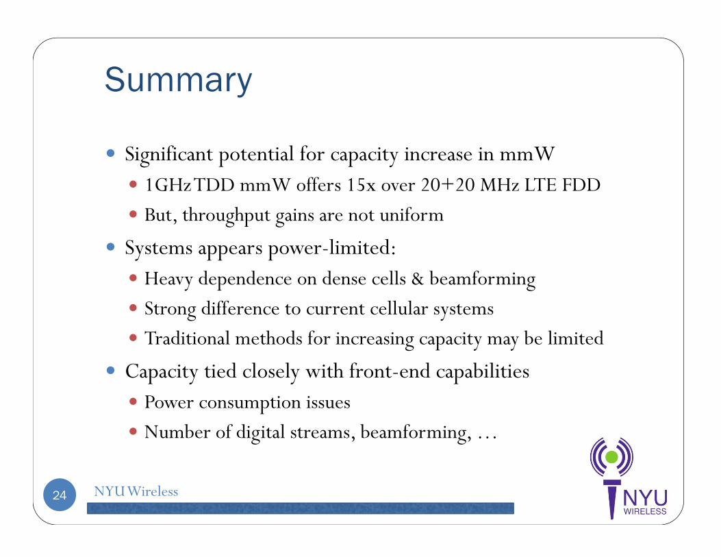
Significant potential for capacity increase in mmW 1GHz TDD mmW offers 15x over 20+20 MHz LTE FDD But, throughput gains are not uniform
Systems appears power-limited: Heavy dependence on dense cells & beamforming Strong difference to current cellular systems Traditional methods for increasing capacity may be limited
Capacity tied closely with front-end capabilities Power consumption issues Number of digital streams, beamforming, …

NYU Wireless
References
25
Khan, Pi, “Millimeter-wave Mobile Broadband (MMB): Unleashing 3-300GHz Spectrum,” Feb 2011, http://www.ieee-wcnc.org/2011/tut/t1.pdf
Pietraski, Britz, Roy, Pragada, Charlton, “Millimeter wave and terahertz communications: Feasibility and challenges,” ZTE Communications, vol. 10, no. 4, pp. 3–12, Dec. 2012.
Akdeniz, Liu, Rangan, Erkip, “Millimeter Wave Picocellular System Evaluation for Urban Deployments”, Apr 2013, http://arxiv.org/abs/1304.3963
Azar et al, “28 GHz propagation measurements for outdoor cellular communications using steerable beam antennas in New York City,” to appear ICC 2013
H. Zhao et al “28 GHz millimeter wave cellular communication measurements for reflection and penetration loss in and around buildings in New York City,” ICC 2013
Samimi,et al “28 GHz angle of arrival and angle of departure analysis for outdoor cellular communications using steerable beam antennas in New York City,” VTC 2013.