
ENCELIUM Energy Management System · Features/Benefits ... The ENCELIUM ®Energy Management System...
20
ENCELIUM ® Energy Management System ENCELIUM GreenBus II ® & Network Cable Guide This manual contains information required to setup an ENCELIUM ® network and ENCELIUM GreenBus II ® troubleshooting procedures. www.sylvania.com/encelium
Transcript of ENCELIUM Energy Management System · Features/Benefits ... The ENCELIUM ®Energy Management System...

ENCELIUM® Energy Management System ENCELIUM GreenBus II® & Network Cable Guide
This manual contains information required to setup an ENCELIUM® network and ENCELIUM GreenBus II® troubleshooting procedures.
www.sylvania.com/encelium
Page ii of 2
ENCELIUM® Energy Management System
ENCELIUM Polaris 3D® Triggers
Table of Contents TABLE OF CONTENTS ....................................................................................................................................................................................................... II ENCELIUM® ENERGY MANAGEMENT SYSTEM ........................................................................................................................................................................... 3 ENCELIUM® AND TENANT NETWORKS...................................................................................................................................................................................... 4
THE ENCELIUM NETWORK.................................................................................................................................................... 4 THE TENANT NETWORK ......................................................................................................................................................... 4 MULTI-TENANTED BUILDING ................................................................................................................................................... 4 SINGLE-TENANTED BUILDING................................................................................................................................................... 5
FIREWALL AND PORT REQUIREMENTS ..................................................................................................................................................................................... 6 REMOTE ACCESS AND CUSTOMER CONNECTIONS.................................................................................................................................................................... 7
ACCESS VIA CUSTOMER/TENANT NETWORK A ............................................................................................................................. 7 Requirements .............................................................................................................................................................. 7 Features/Benefits ........................................................................................................................................................ 7
ACCESS VIA CUSTOMER/TENANT NETWORK B ............................................................................................................................. 8 Requirements .............................................................................................................................................................. 8 Features/Benefits ........................................................................................................................................................ 8
ACCESS VIA DEDICATED DSL.................................................................................................................................................... 9 Requirements .............................................................................................................................................................. 9 Features/Benefits ........................................................................................................................................................ 9 Pros ............................................................................................................................................................................. 9 Cons ............................................................................................................................................................................ 9
ACCESS VIA WIRELESS ROUTER .............................................................................................................................................. 10 Requirements ............................................................................................................................................................ 10 Pros ........................................................................................................................................................................... 10 Cons .......................................................................................................................................................................... 10
ACCESS VIA WEB MEETING ................................................................................................................................................... 11 Requirements ............................................................................................................................................................ 11 Pros ........................................................................................................................................................................... 11 Cons .......................................................................................................................................................................... 11
ACCESS VIA WEB SERVICE ..................................................................................................................................................... 12 Requirements ............................................................................................................................................................ 12 Features/Benefits ...................................................................................................................................................... 12
ENCELIUM® GREENBUS II® NETWORK ..................................................................................................................................................................................... 13
ECU G4 CONNECTIONS ....................................................................................................................................................... 13 ECU G4 Front Panel Touch Buttons ............................................................................................................................. 13
ENCELIUM® GREENBUS II® CABLE ........................................................................................................................................................................................... 15
COMPATIBLE CONNECTORS ................................................................................................................................................... 15 FABRICATING ENCELIUM GREENBUS II CABLE ......................................................................................................................... 15
ENCELIUM® GREENBUS II® TESTING & TROUBLESHOOTING ..................................................................................................................................................... 17
OPERATING THE ITT ............................................................................................................................................................ 17 TESTING THE ENCELIUM GREENBUS II CHANNELS .................................................................................................................... 17 RECOMMENDED TESTING STRATEGY ........................................................................................................................................ 17 TURNING ON AN LCM ......................................................................................................................................................... 18 FACTS TO NOTE WHEN USING ITT ........................................................................................................................................... 18
Protection Mode ........................................................................................................................................................ 18 ECU Location ............................................................................................................................................................. 18 Short on Channel ....................................................................................................................................................... 18
DETERMINING THE LOCATION OF A FAULT ................................................................................................................................. 19 Determining the Location with Short .......................................................................................................................... 19

Page 3 of 3
ENCELIUM® Energy Management System
ENCELIUM GreenBus II® & Network Cable Guide
ENCELIUM® Energy Management System
The ENCELIUM® Energy Management System (EMS) comprises multiple ENCELIUM GreenBus II® networks, the ENCELIUM network and the tenant network. The ECU communicates with sensors and light fixtures via a dedicated ENCELIUM GreenBus II network. All other communication utilizes on standard network 10/100 Base-T Ethernet, TCP/IP & UDP protocols.
As shown below, an ENCELIUM network is comprised of one or more ECUs and one SSU all connected together using a standard Ethernet switch. Within the ENCELIUM network, individual devices are assigned static IP addresses.
An ENCELIUM network can be implemented using new dedicated physical cabling or the existing infrastructure can be used. Using the existing infrastructure will involve support from local IT for IP and port assignment and if required, VLAN setup.
Two Network Interface Cards (NICs) are installed in each ECU (Energy Control Unit). One of them is used for connectivity with the ENCELIUM network while the other can be used for connectivity with the tenant network.

Page 4 of 4
ENCELIUM® Energy Management System
ENCELIUM GreenBus II® & Network Cable Guide
ENCELIUM® and Tenant Networks
The ENCELIUM Network
The ENCELIUM Network must be used on every ECU at site. All ECUs must be able to communicate with the SSU via the ENCELIUM Network and all ECUs must be able to communicate with each other via the ENCELIUM Network. It is ideal to have ECUs communicating with the SSU without firewall restrictions. If a firewall is being used, see Firewall and Port Requirements.
The Tenant Network
The Tenant Network port on the ECU has some unique properties. Since there is a firewall between the ENCELIUM port and the Tenant port, it is not possible to initiate communication from any device on the ENCELIUM network to the customer network. The Tenant network is only able to listen and forward queries. A single connection to the Tenant port on any ECU will allow full access for ENCELIUM Polaris 3D® and PCSTM/PCWTM.
Multi-Tenanted Building
In a building occupied by multiple tenants, each tenant can connect to their respective ECUs via the Tenant Network Interface. With user account control in ENCELIUM Polaris 3D, each tenant will only have access to their specific area of the building.
Communications among multiple ECUs and the SSU are maintained by connecting them all to a switch. Unless the existing network is being used, a standard network switch like the one below is used to connect all ENCELIUM devices.
If the network switch has an ‘uplink’ port, be sure not to connect ECU and SSU to this port. This port is reserved for Internet connectivity.
Page 5 of 5
ENCELIUM® Energy Management System
ENCELIUM Polaris 3D® Triggers
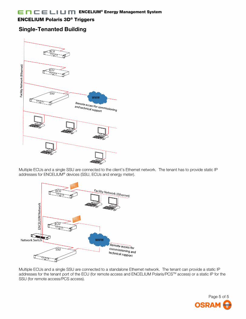
Single-Tenanted Building
Multiple ECUs and a single SSU are connected to the client’s Ethernet network. The tenant has to provide static IP addresses for ENCELIUM® devices (SSU, ECUs and energy meter).
Multiple ECUs and a single SSU are connected to a standalone Ethernet network. The tenant can provide a static IP addresses for the tenant port of the ECU (for remote access and ENCELIUM Polaris/PCSTM access) or a static IP for the SSU (for remote access/PCS access).
Page 6 of 6
ENCELIUM® Energy Management System
ENCELIUM Polaris 3D® Triggers
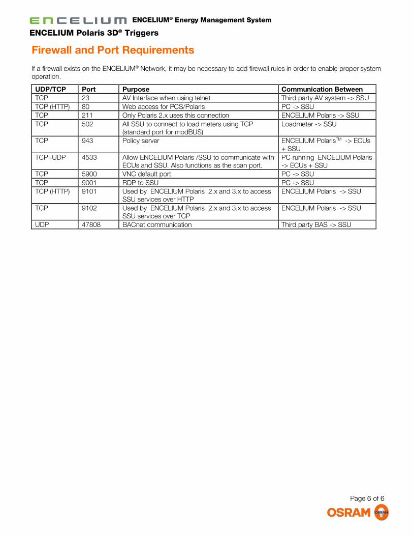
Firewall and Port Requirements
If a firewall exists on the ENCELIUM® Network, it may be necessary to add firewall rules in order to enable proper system operation.
UDP/TCP Port Purpose Communication Between TCP 23 AV Interface when using telnet Third party AV system -> SSU TCP (HTTP) 80 Web access for PCS/Polaris PC -> SSU TCP 211 Only Polaris 2.x uses this connection ENCELIUM Polaris -> SSU TCP 502 All SSU to connect to load meters using TCP
(standard port for modBUS) Loadmeter -> SSU
TCP 943 Policy server ENCELIUM PolarisTM -> ECUs + SSU
TCP+UDP 4533 Allow ENCELIUM Polaris /SSU to communicate with ECUs and SSU. Also functions as the scan port.
PC running ENCELIUM Polaris -> ECUs + SSU
TCP 5900 VNC default port PC -> SSU TCP 9001 RDP to SSU PC -> SSU TCP (HTTP) 9101 Used by ENCELIUM Polaris 2.x and 3.x to access
SSU services over HTTP ENCELIUM Polaris -> SSU
TCP 9102 Used by ENCELIUM Polaris 2.x and 3.x to access SSU services over TCP
ENCELIUM Polaris -> SSU
UDP 47808 BACnet communication Third party BAS -> SSU

Page 7 of 7
ENCELIUM® Energy Management System
ENCELIUM Polaris 3D® Triggers
Remote Access and Customer Connections
Access via Customer/Tenant Network A
ENCELIUM® support personnel require limited access to reach an ECU on client site. Upon entering the network, the static IP address provided by the client will be used to get access to the ENCELIUM Network.
Requirements
• Static IP address on the customer network for the Tenant NIC of the ECU
• Remote connection to customer network via client preferred method (VPN, external IP address with firewall port-forwarding etc.)
Features/Benefits
• Tenant connection enables system for PCSTM and local PCWTM use
• The firewall on the ECU only allows incoming connections
• Allows users on the customer network to access the ENCELIUM Polaris 3D® web application
• All ECU’s have two network cards, so any ECU can be used to connect to the customer network
• No monthly access fees
• Customer can lock down access to specific incoming IP address and ports

Page 8 of 8
ENCELIUM® Energy Management System
ENCELIUM Polaris 3D® Triggers
Access via Customer/Tenant Network B
Some ENCELIUM® installations use the customer network as the network backbone for the ENCELIUM equipment. This decision is usually made before installation begins and is typically done to save on additional costs and logistics of running a new network inside a building. Support personnel require limited access to reach the SSU on client site.
Requirements
• Static IP address on the customer network for the Encelium NIC of all ECUs and the SSU
• Remote connection to customer network via client preferred method (VPN, external IP address with firewall port-forwarding etc.)
Features/Benefits
• All software features can be accessed from the customer PCs: PCSTM , PCWTM and Polaris 3D®
• ENCELIUM equipment supports gateways, allowing them to be configured to run on VLANs for additional security
• No monthly access fees
• Customer can lock down access to specific incoming IP address and ports

Page 9 of 9
ENCELIUM® Energy Management System
ENCELIUM Polaris 3D® Triggers
Access via Dedicated DSL
ENCELIUM® support personnel will have direct and dedicated access to ENCELIUM SSU via customer provided dedicated DSL. Connection to the customer network is only required if access is desired from the PCs on the customer network.
Requirements
• DSL line connected to second port on the SSU or directly into the ENCELIUM Network
• May require DNS service if a static IP address is not available from ISP
• Local access for Polaris, PCS or PCW only available if connection to the customer network is made via an ECU
Features/Benefits
• Enable system for PCW without connection to the customer network
Pros
• Allows unattended access
• Not using customer network
• Fast
Cons
• Monthly fee

Page 10 of 10
ENCELIUM® Energy Management System
ENCELIUM Polaris 3D® Triggers
Access via Wireless Router
ENCELIUM® support personnel access ENCELIUM network via a wireless network. An ENCELIUM configured wireless router with connections to ENCELIUM network at the customer site will be accessed using a mobile internet stick. Connection to the customer network is only required if access is desired from the PCs on the customer network.
Requirements
• ENCELIUM configured wireless router
• Approved cellular modem (aircard)
• Local access for Polaris, PCS or PCW only available if connection to the customer network is made via an ECU
Pros
• Not using customer network
• Allows unattended access
Cons
• Monthly fee for service
• Dependant on wireless signal strength
• Slow
Page 11 of 11
ENCELIUM® Energy Management System
ENCELIUM Polaris 3D® Triggers
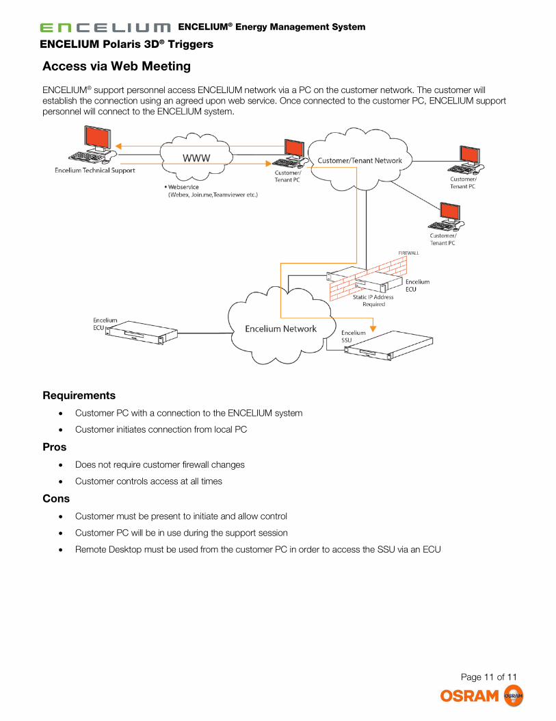
Access via Web Meeting
ENCELIUM® support personnel access ENCELIUM network via a PC on the customer network. The customer will establish the connection using an agreed upon web service. Once connected to the customer PC, ENCELIUM support personnel will connect to the ENCELIUM system.
Requirements
• Customer PC with a connection to the ENCELIUM system
• Customer initiates connection from local PC
Pros
• Does not require customer firewall changes
• Customer controls access at all times
Cons
• Customer must be present to initiate and allow control
• Customer PC will be in use during the support session
• Remote Desktop must be used from the customer PC in order to access the SSU via an ECU

Page 12 of 12
ENCELIUM® Energy Management System
ENCELIUM Polaris 3D® Triggers
Access via Web Service
ENCELIUM® support personnel access the SSU via an Internet connection. The SSU will have a web service installed that can only be accessed my ENCELIUM® support personnel. Connection to the customer network is only required if access is desired from the PCs on the customer network.
Requirements
• Internet connection to second port on the SSU
• Web service installed by Encelium
• Local access for Polaris, PCS or PCW only available if connection to the customer network is made via an ECU
Features/Benefits
• Allows unattended access
• Fast

Page 13 of 13
ENCELIUM® Energy Management System
ENCELIUM Polaris 3D® Triggers
ENCELIUM® GreenBus II® Network
Each ENCELIUM GreenBus II channel supports a ENCELIUM GreenBus II network consisting of field modules and wall stations. Sensors and light fixtures are in turn connected to the modules.
Each ENCELIUM GreenBus II channel can have 100 addressable nodes. The ENCELIUM GreenBus II cable connects directly to Field Modules, Lighting Controllers and low voltage Relay Modules.
ECU G4 Connections
The ENCELIUM GreenBus II network cables connect to ECU ports 1 – 8.
ECU G4 Front Panel Touch Buttons
ENCELIUM GreenBus II channel status indicator LEDs are numbered 1-8. Green on the LED indicates all is well with the channel. Red LED indicates a short on the channel. For more on diagnosing the problem, see section Determining the Location with Short.

Page 14 of 14
ENCELIUM® Energy Management System
ENCELIUM Polaris 3D® Triggers
Network LED
The LED is green only. The LED will mimic the rear LED on the Ethernet port; the LED will flash indicating network activity. The LED will not distinguish between 10 or 100MB/s.
Channel 1 – 8 LEDs
The Channels can display Green, Orange and Red. The Channel LED will display solid Green if the channel is operating normally, the channel will blink Green if the channel is communicating with devices.
The channel will display Orange if the channel is experiencing or recovering from abnormal behaviour.
The channel will display Red if the channel is Foldback Protection or Foldback Recovery.
The channel will blink Red if the channel detects line voltage on the bus. In this case, all other front panel LEDs will synchronously blink orange to indicate a dangerous condition.
Lock LED
The Lock LED will display Orange if the ECU is locked. Otherwise the LED will be off.
Busy LED
When this LED is in Solid Bright Orange, it indicates the ECU is in the process of executing a function which the user has activated through the front panel. Since no other function can be activated during this time, the LEDs of other function buttons will be off during this time (except Installation Mode).
Additionally, when the ECU is powering up or restarted via Polaris, the Busy LED will blink Green during start up. The LED will then become off upon detection of channel communication.
Upon power up, the Busy LED will be blinking until the ECU firmware until the front panel microcontroller observes the first communication with a channel. At this time, it will stop blinking the Busy LED and reflect the proper state of the channels (this way, the channel LEDs can be used to observe traffic in Pass-Through mode).
Installation Mode
This is a toggle function that is either active or inactive. When the mode is active, the LED will be lit bright. Otherwise faint (as the function is available).
To activate Installation Mode, press the Installation Mode button and then the Confirm button.
While Installation Mode is active, every keypad connected to any channel will automatically cycle all lights through the steps 100%, 25% and 0%. All buttons on all wall controllers will work the same.
When Installation Mode is activated, the Installation Mode LED and Cycle LED will become Solid Bright Green. The Channel and Network LEDs will go Dim and all other LEDs will turn offf. The user can press the Cycle button to cycle all lights through the steps 100%, 25% and 0%. To deactivate Installation Mode press the Installation Mode button.
Installation Mode automatically deactivates after 10 minutes of inactivity.
Cycle 100% 25% 0%
The Cycle Function allows the user to cycle all lights connected to the ECU through the steps 100%, 25% and 0%.
To use the Cycle Function, press the Cycle button and then the Confirm button. Continue pressing the Cycle followed by Confirm to step through 100%,25% and 0% commands.
When the Cycle button is used while in Installation Mode, pressing the Confirm button is not required after each Cycle button press.
Page 15 of 15
ENCELIUM® Energy Management System
ENCELIUM Polaris 3D® Triggers
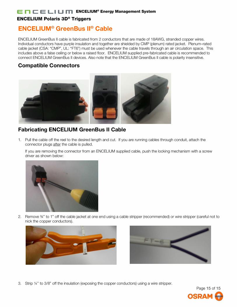
ENCELIUM® GreenBus II® Cable
ENCELIUM GreenBus II cable is fabricated from 2 conductors that are made of 18AWG, stranded copper wires. Individual conductors have purple insulation and together are shielded by CMP (plenum) rated jacket. Plenum–rated cable jacket (CSA: “CMP”, UL: “FT6”) must be used whenever the cable travels through an air circulation space. This includes above a false ceiling or below a raised floor. ENCELIUM supplied pre-fabricated cable is recommended to connect ENCELIUM GreenBus II devices. Also note that the ENCELIUM GreenBus II cable is polarity insensitive.
Compatible Connectors
Fabricating ENCELIUM GreenBus II Cable
1. Pull the cable off the reel to the desired length and cut. If you are running cables through conduit, attach the connector plugs after the cable is pulled.
If you are removing the connector from an ENCELIUM supplied cable, push the locking mechanism with a screw driver as shown below:
2. Remove ¾” to 1” off the cable jacket at one end using a cable stripper (recommended) or wire stripper (careful not to nick the copper conductors).
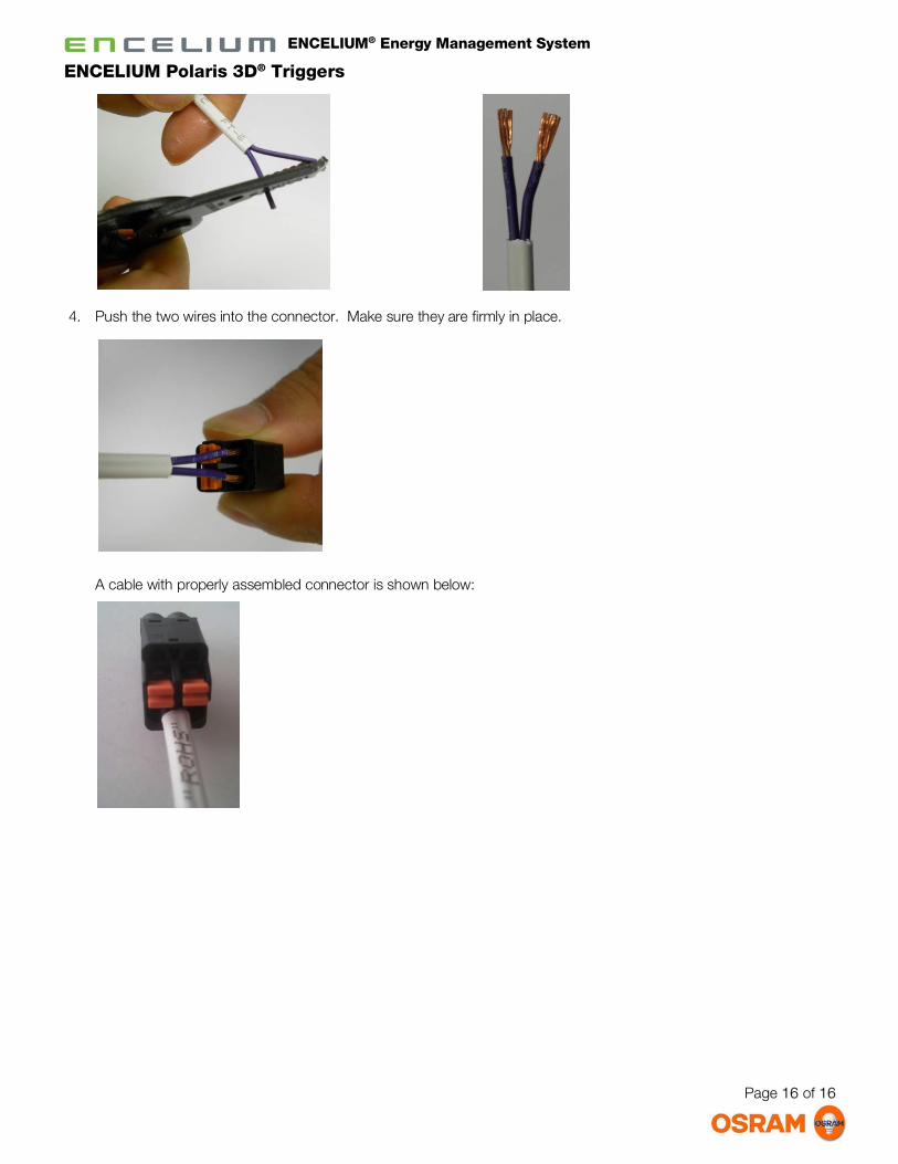
3. Strip ¼” to 3/8” off the insulation (exposing the copper conductors) using a wire stripper.
Page 16 of 16
ENCELIUM® Energy Management System
ENCELIUM Polaris 3D® Triggers
4. Push the two wires into the connector. Make sure they are firmly in place.
A cable with properly assembled connector is shown below:

Page 17 of 17
ENCELIUM® Energy Management System
ENCELIUM Polaris 3D® Triggers
ENCELIUM® GreenBus II® Testing & Troubleshooting
Operating the ITT
The ITT (ENCELIUM GreenBus II Installation and Testing Tool) supplied by ENCELIUM is used to test all ENCELIUM GreenBus II wiring.
The ITT tool does not need to be turned on, simply plug in a ENCELIUM GreenBus II cable to start testing.
With no connections, both LEDs should be OFF as shown:
Testing the ENCELIUM GreenBus II Channels
To test the ENCELIUM GreenBus II channels:
1. Connect power to the ECU G4.
2. Quick flickering of GreenBus Channel Indicator LEDs indicates normal ECU G4 operating mode.
3. Plug the first channel into one of the ECU G4 ports numbered 1-8. When a channel is plugged in for the first time, the ECU G4 may reboot, wait until the LED on the front is flickering quickly before proceeding.
4. Plug the other end of the cable into the ITT.
a. If the channel is good, the Green LED will flash rapidly:
b. If the channel has a communication/power problem, the Green LED will remain off:
5. As you add devices and cables to the channel, you can continue testing at the end of each cable to ensure that the channel is working.
6. Repeat steps 3. - 5. for each channel.
Recommended Testing Strategy
It is recommended to test as you go:
1. Plug in power to the ECU first.
2. Plug in the first ENCELIUM GreenBus II cable into the ECU.
3. Before plugging the other end into the first module, check the communication with the ITT. Look for flashing Green LED.
4. Before plugging in each subsequent module, check the communication with the ITT.
If testing is not performed until the installation is complete, any problem along a GreenBus II run will cause a fault and then will have to be located. This takes time, and will probably require going back into the ceiling.
ENCELIUM GreenBus II Port Yellow & Green LEDs Button

Page 18 of 18
ENCELIUM® Energy Management System
ENCELIUM Polaris 3D® Triggers
If testing is performed as you go, any faults can be quickly located while you are in the ceiling and can be corrected immediately.
When you get to the end of the channel run by this process, it will then all be tested and working correctly.
Turning on an LCM
During shipping and handling of an LCM, the internal relay may become open. This means that once wired to a fixture, power will not pass through the LCM. In these cases, it may be necessary to manually close the relay in the LCM to ensure that the fixture will turn on.
The LCMs will turn ON automatically when the ENCELIUM GreenBus II cable is connected to an ECU.
To turn on an LCM using the ITT, follow the steps below:
1. With the fixtures energized, connect ITT directly to the LCM (via one of its ports).
2. Press and hold the Button on the ITT for approximately 3 seconds. The Yellow LED will turn solid; continue to hold the button until the Yellow LED turns off.
Resulting click sound indicates the LCM relay closing (this will only close the relay, not toggle it).
Facts to note when using ITT
Protection Mode
ECUs can go into a temporary “protection mode” when numerous devices such as a whole channel or large section of a channel are plugged in.
After any operation that involves the ENCELIUM GreenBus II, always wait 15–30 seconds to allow the ECU to recover. Otherwise, you may erroneously assume there is a problem with the ECU.
ECU Location
During troubleshooting, one end of the channel terminates at an ECU while the other end terminating at an ITT.
Short on Channel
ENCELIUM GreenBus II Channel Status Indicator turns RED if there is a short on the ENCELIUM GreenBus II (usually caused when both wires in the GB II cable are touching each other). Connecting the ITT on the other end of the cable will not resolve this issue.

Page 19 of 19
ENCELIUM® Energy Management System
ENCELIUM Polaris 3D® Triggers
Determining the Location of a Fault
The ITT can only identify channel continuity problem between where it is connected and the ECU. Use the “divide and conquer” approach to determine the exact location of the fault. First, connect the ITT approximately half way between the current location and the ECU end of the cable. If the problem continues to appear, move half way again between the current location and the ECU end of the cable. Continue until you find the location of the problem.
Consider the following example. The example shows only 10 LCMs, but you may have up to 100 LCMs on each of the 8 ECU channels.
LCM 1 LCM 2 LCM 3 LCM 6 LCM 7 LCM 8 LCM 9 LCM 10LCM 4ECU LCM 5
1. Connect the ITT at the end of the cable and check for faults. Faults can be anywhere between LCM 10 and the
ECU.
LCM 1 LCM 2 LCM 3 LCM 6 LCM 7 LCM 8 LCM 9 LCM 10LCM 4ECU LCM 5 ITT
2. Move to the ECU and check the first connection coming out of the ECU (connection between the ECU & LCM 1).
This helps determine if the problem is with the first cable (“home run” cable) or with the ECU port. If the first connection has no problems, continue with the next step.
The LED pattern indicates a connection that has no problems and the LED pattern indicates problem within the channel.
3. Calculating from the end of the cable, move halfway back to the ECU. In this case move to LCM 5 and test from there.
LCM 1 LCM 2 LCM 3 LCM 6 LCM 7 LCM 8 LCM 9 LCM 10LCM 4ECU LCM 5
Test Hereif good, go right
ITT
4. If the fault no longer appears, you know the problem must lie between the end of the cable (towards LCM 10) and LCM 5. Go back half-way toward the end of the cable and test again.
5. If the fault continues to appear, you know the problem must lie between the ECU and LCM 5, so you go back half-way toward the ECU and test again.
6. Repeat the process of testing and determining the direction to move until the location where the fault occurs is found.
The fault might be with the ENCELIUM® GreenBus IITM cable or with the LCM. It is important both the GreenBus II cable and the LCM attached to it get tested. For more on diagnosing the problem, see ENCELIUM GreenBus II Testing & Troubleshooting.
Determining the Location with Short
If a short circuit occurs, the LCMs will disconnect the channel at the location of the short and the ECU Channel Status Indicator will turn red. In order to find this short, you can follow the procedures above in Determining the Location of a Fault. The ITT will indicate an “open” circuit when there is a short. Once the problematic wire has been removed, the ECU will recover and apply power and communication to the remainder of the channel. The Channel Status Indicator LED will return to green.

Americas Headquarters
100 Endicott Street
Danvers, MA 01923 USA
Phone 1-800-LIGHTBULB
www.osram-americas.com
OSRAM is a registered trademark of OSRAM GmbH. ENCELIUM, GreenBus II and Polaris 3D are registered trademarks of OSRAM SYLVANIA, Inc.
Specification subject to change without notice
© 2015 OSRAM