
EN / ACS800-67 wind turbine converters System description and … · 2018-05-09 · This manual...
120
ABB wind turbine converters System description and start-up guide ACS800-67 wind turbine converters
Transcript of EN / ACS800-67 wind turbine converters System description and … · 2018-05-09 · This manual...

ABB wind turbine converters
System description and start-up guideACS800-67 wind turbine converters

List of related manuals
For manuals, contact your local ABB representative.
ACS800-67 manuals Code (English)
ACS800-67 wind turbine converters for asynchronous slip ring generators hardware manual
3AFE68392454
ACS800-67 wind turbine converters system description and start-up guide
3AUA0000095094
Firmware manuals
ACS800 IGBT supply control program firmware manual 3AFE68315735
ACS800 grid-side control program firmware manual 3AUA0000075077
ACS800-67(LC) doubly-fed induction generator control program firmware manual
3AUA0000071689
Option manuals
Manuals for fieldbus adapters, etc.

4. Start-up with medium voltage stator
3. Start-up with low voltage stator
Table of contents
System description and start-up guide
ACS800-67 wind turbine converters
3AUA0000095094 Rev BENEFFECTIVE: 2017-12-31
2017 ABB Oy. All Rights Reserved.

5
Table of contents
List of related manuals . . . . . . . . . . . . . . . . . . . . . . . . . . . . . . . . . . . . . . . . . . . . . . . . . . . 2
1. About this manual
What this chapter contains . . . . . . . . . . . . . . . . . . . . . . . . . . . . . . . . . . . . . . . . . . . . . . . . 9Applicability . . . . . . . . . . . . . . . . . . . . . . . . . . . . . . . . . . . . . . . . . . . . . . . . . . . . . . . . . . . . 9Safety instructions . . . . . . . . . . . . . . . . . . . . . . . . . . . . . . . . . . . . . . . . . . . . . . . . . . . . . . . 9Target audience . . . . . . . . . . . . . . . . . . . . . . . . . . . . . . . . . . . . . . . . . . . . . . . . . . . . . . . 10Purpose of the manual . . . . . . . . . . . . . . . . . . . . . . . . . . . . . . . . . . . . . . . . . . . . . . . . . . 10Contents of this manual . . . . . . . . . . . . . . . . . . . . . . . . . . . . . . . . . . . . . . . . . . . . . . . . . 10Contents of other related manuals . . . . . . . . . . . . . . . . . . . . . . . . . . . . . . . . . . . . . . . . . 11
DriveWindow . . . . . . . . . . . . . . . . . . . . . . . . . . . . . . . . . . . . . . . . . . . . . . . . . . . . . . . 11Further information . . . . . . . . . . . . . . . . . . . . . . . . . . . . . . . . . . . . . . . . . . . . . . . . . . . . . 12Terms and abbreviations . . . . . . . . . . . . . . . . . . . . . . . . . . . . . . . . . . . . . . . . . . . . . . . . . 12
2. System description
What this chapter contains . . . . . . . . . . . . . . . . . . . . . . . . . . . . . . . . . . . . . . . . . . . . . . . 13General . . . . . . . . . . . . . . . . . . . . . . . . . . . . . . . . . . . . . . . . . . . . . . . . . . . . . . . . . . . . . . 13
ACS800-67 . . . . . . . . . . . . . . . . . . . . . . . . . . . . . . . . . . . . . . . . . . . . . . . . . . . . . . . . . 14Wind turbine system with low voltage stator (690 V) . . . . . . . . . . . . . . . . . . . . . . . 15Wind turbine system with medium voltage stator (> 1000 V) . . . . . . . . . . . . . . . . . 15
Converter system . . . . . . . . . . . . . . . . . . . . . . . . . . . . . . . . . . . . . . . . . . . . . . . . . . . . 16Control of generator power . . . . . . . . . . . . . . . . . . . . . . . . . . . . . . . . . . . . . . . . . . 18Operational speed range of a typical wind turbine . . . . . . . . . . . . . . . . . . . . . . . . . 19Wind turbine system operating speed area . . . . . . . . . . . . . . . . . . . . . . . . . . . . . . 20Control of torque and reactive power via rotor-side converter . . . . . . . . . . . . . . . . 21Control of torque and reactive power via grid-side converter . . . . . . . . . . . . . . . . 25
Overview of converter interfaces . . . . . . . . . . . . . . . . . . . . . . . . . . . . . . . . . . . . . . . . . . . 27Converter control . . . . . . . . . . . . . . . . . . . . . . . . . . . . . . . . . . . . . . . . . . . . . . . . . . . . . . . 28
General . . . . . . . . . . . . . . . . . . . . . . . . . . . . . . . . . . . . . . . . . . . . . . . . . . . . . . . . . . . . 28PLC interface . . . . . . . . . . . . . . . . . . . . . . . . . . . . . . . . . . . . . . . . . . . . . . . . . . . . . . . 28Fieldbus control . . . . . . . . . . . . . . . . . . . . . . . . . . . . . . . . . . . . . . . . . . . . . . . . . . . . . 29
Grid codes . . . . . . . . . . . . . . . . . . . . . . . . . . . . . . . . . . . . . . . . . . . . . . . . . . . . . . . . . . . . 30Example of grid code regulations in different countries . . . . . . . . . . . . . . . . . . . . . . . 30
Example limit curves . . . . . . . . . . . . . . . . . . . . . . . . . . . . . . . . . . . . . . . . . . . . . . . 31Description of parameter settings . . . . . . . . . . . . . . . . . . . . . . . . . . . . . . . . . . . . . 31
Grid fault ride-trough capability . . . . . . . . . . . . . . . . . . . . . . . . . . . . . . . . . . . . . . . . . . . . 32Grid support . . . . . . . . . . . . . . . . . . . . . . . . . . . . . . . . . . . . . . . . . . . . . . . . . . . . . . . . . . 34
Grid support areas . . . . . . . . . . . . . . . . . . . . . . . . . . . . . . . . . . . . . . . . . . . . . . . . . . . 34Grid support example . . . . . . . . . . . . . . . . . . . . . . . . . . . . . . . . . . . . . . . . . . . . . . . . . 35
Stator circuit connection to grid . . . . . . . . . . . . . . . . . . . . . . . . . . . . . . . . . . . . . . . . . . . . 36Stator breaker only (par. 16.20 GRID CONNECT MODE set to MCB3) . . . . . . . . . . 36Main circuit breaker (par. 16.20 GRID CONNECT MODE set to MCB1+MCB3/A) . . 37Main circuit breaker (par. 16.20 GRID CONNECT MODE set to MCB1+MCB3/B) . . 37Stator contactor (par. 16.20 GRID CONNECT MODE set to MCB1+MCB3/C) . . . . . 38Settings . . . . . . . . . . . . . . . . . . . . . . . . . . . . . . . . . . . . . . . . . . . . . . . . . . . . . . . . . . . . 38Grid connection procedure . . . . . . . . . . . . . . . . . . . . . . . . . . . . . . . . . . . . . . . . . . . . . 39
Phasing checks executed at start-up . . . . . . . . . . . . . . . . . . . . . . . . . . . . . . . . . . . . . . . 40Grid phasing . . . . . . . . . . . . . . . . . . . . . . . . . . . . . . . . . . . . . . . . . . . . . . . . . . . . . . . . 40
6
Encoder phasing . . . . . . . . . . . . . . . . . . . . . . . . . . . . . . . . . . . . . . . . . . . . . . . . . . . . 40Stator phasing . . . . . . . . . . . . . . . . . . . . . . . . . . . . . . . . . . . . . . . . . . . . . . . . . . . . . . 40Rotor phasing . . . . . . . . . . . . . . . . . . . . . . . . . . . . . . . . . . . . . . . . . . . . . . . . . . . . . . 40
3. Start-up with low voltage stator
What this chapter contains . . . . . . . . . . . . . . . . . . . . . . . . . . . . . . . . . . . . . . . . . . . . . . 41How to start-up the converter . . . . . . . . . . . . . . . . . . . . . . . . . . . . . . . . . . . . . . . . . . . . 42
Safety . . . . . . . . . . . . . . . . . . . . . . . . . . . . . . . . . . . . . . . . . . . . . . . . . . . . . . . . . . . . 42Power-up . . . . . . . . . . . . . . . . . . . . . . . . . . . . . . . . . . . . . . . . . . . . . . . . . . . . . . . . . . 42Manual start-up data entering . . . . . . . . . . . . . . . . . . . . . . . . . . . . . . . . . . . . . . . . . . 42Time setting . . . . . . . . . . . . . . . . . . . . . . . . . . . . . . . . . . . . . . . . . . . . . . . . . . . . . . . . 45Digital inputs . . . . . . . . . . . . . . . . . . . . . . . . . . . . . . . . . . . . . . . . . . . . . . . . . . . . . . . 45Grid-side converter and crowbar test . . . . . . . . . . . . . . . . . . . . . . . . . . . . . . . . . . . . 45Grid-side converter and DC chopper test . . . . . . . . . . . . . . . . . . . . . . . . . . . . . . . . . 48Rotor-side converter test . . . . . . . . . . . . . . . . . . . . . . . . . . . . . . . . . . . . . . . . . . . . . . 50Stator voltage synchronization test . . . . . . . . . . . . . . . . . . . . . . . . . . . . . . . . . . . . . . 51Start-up of the air damper . . . . . . . . . . . . . . . . . . . . . . . . . . . . . . . . . . . . . . . . . . . . . 53Final settings . . . . . . . . . . . . . . . . . . . . . . . . . . . . . . . . . . . . . . . . . . . . . . . . . . . . . . . 54
4. Start-up with medium voltage stator
What this chapter contains . . . . . . . . . . . . . . . . . . . . . . . . . . . . . . . . . . . . . . . . . . . . . . 55How to start-up the converter . . . . . . . . . . . . . . . . . . . . . . . . . . . . . . . . . . . . . . . . . . . . 56
Safety . . . . . . . . . . . . . . . . . . . . . . . . . . . . . . . . . . . . . . . . . . . . . . . . . . . . . . . . . . . . 56Power-up . . . . . . . . . . . . . . . . . . . . . . . . . . . . . . . . . . . . . . . . . . . . . . . . . . . . . . . . . . 56Manual start-up data entering . . . . . . . . . . . . . . . . . . . . . . . . . . . . . . . . . . . . . . . . . . 56Time setting . . . . . . . . . . . . . . . . . . . . . . . . . . . . . . . . . . . . . . . . . . . . . . . . . . . . . . . . 58Digital inputs . . . . . . . . . . . . . . . . . . . . . . . . . . . . . . . . . . . . . . . . . . . . . . . . . . . . . . . 58Grid-side converter and crowbar test . . . . . . . . . . . . . . . . . . . . . . . . . . . . . . . . . . . . 59Rotor-side converter test . . . . . . . . . . . . . . . . . . . . . . . . . . . . . . . . . . . . . . . . . . . . . . 62Stator voltage synchronization test . . . . . . . . . . . . . . . . . . . . . . . . . . . . . . . . . . . . . . 63Start-up of the air damper . . . . . . . . . . . . . . . . . . . . . . . . . . . . . . . . . . . . . . . . . . . . . 65Final settings . . . . . . . . . . . . . . . . . . . . . . . . . . . . . . . . . . . . . . . . . . . . . . . . . . . . . . . 66
Starting sequence . . . . . . . . . . . . . . . . . . . . . . . . . . . . . . . . . . . . . . . . . . . . . . . . . . . . . 67Start-up measurements . . . . . . . . . . . . . . . . . . . . . . . . . . . . . . . . . . . . . . . . . . . . . . . . . 70
Stator current transformer polarity check . . . . . . . . . . . . . . . . . . . . . . . . . . . . . . . . . 70Phase U test . . . . . . . . . . . . . . . . . . . . . . . . . . . . . . . . . . . . . . . . . . . . . . . . . . . . . 70Phase W test . . . . . . . . . . . . . . . . . . . . . . . . . . . . . . . . . . . . . . . . . . . . . . . . . . . . 72
Test at zero speed . . . . . . . . . . . . . . . . . . . . . . . . . . . . . . . . . . . . . . . . . . . . . . . . . . 73Start in local control mode . . . . . . . . . . . . . . . . . . . . . . . . . . . . . . . . . . . . . . . . . . . . . 74Voltage and current waveform examples . . . . . . . . . . . . . . . . . . . . . . . . . . . . . . . . . 75
5. Practical examples
What this chapter contains . . . . . . . . . . . . . . . . . . . . . . . . . . . . . . . . . . . . . . . . . . . . . . 77Setting up the fieldbus . . . . . . . . . . . . . . . . . . . . . . . . . . . . . . . . . . . . . . . . . . . . . . . . . . 77
Fieldbus interfaces . . . . . . . . . . . . . . . . . . . . . . . . . . . . . . . . . . . . . . . . . . . . . . . . . . 77Entering start-up data and torque settings . . . . . . . . . . . . . . . . . . . . . . . . . . . . . . . . . . . 78
Calculating/setting the motor nominal torque . . . . . . . . . . . . . . . . . . . . . . . . . . . . . . 78Torque set-point . . . . . . . . . . . . . . . . . . . . . . . . . . . . . . . . . . . . . . . . . . . . . . . . . . . . 78
Stator current and voltage measurement . . . . . . . . . . . . . . . . . . . . . . . . . . . . . . . . . . . 79NUIM-6x voltage measurement . . . . . . . . . . . . . . . . . . . . . . . . . . . . . . . . . . . . . . . . 79NUIM-1x voltage measurement . . . . . . . . . . . . . . . . . . . . . . . . . . . . . . . . . . . . . . . . 79

7
NUIM-1x and NUIM-6x current measurements . . . . . . . . . . . . . . . . . . . . . . . . . . . . . 79Generator data . . . . . . . . . . . . . . . . . . . . . . . . . . . . . . . . . . . . . . . . . . . . . . . . . . . . . . . . 81
Generator rating plate equivalent circuit parameters . . . . . . . . . . . . . . . . . . . . . . . . . 81Parameters of parameter group 99 . . . . . . . . . . . . . . . . . . . . . . . . . . . . . . . . . . . . . . 83
Parameter 99.05 MOTOR NOM SPEED . . . . . . . . . . . . . . . . . . . . . . . . . . . . . . . . 84Generator nominal power calculation . . . . . . . . . . . . . . . . . . . . . . . . . . . . . . . . . . . . . 85Setting the equivalent circuit values to the parameters . . . . . . . . . . . . . . . . . . . . . . . 85Mutual inductance Xm and rotor resistance Rr calculations . . . . . . . . . . . . . . . . . . . . 86
Current measurement of the grid-side converter . . . . . . . . . . . . . . . . . . . . . . . . . . . . . . 87Example . . . . . . . . . . . . . . . . . . . . . . . . . . . . . . . . . . . . . . . . . . . . . . . . . . . . . . . . . . . 88
ABB Drives communication profile . . . . . . . . . . . . . . . . . . . . . . . . . . . . . . . . . . . . . . . . . 90Starting sequence . . . . . . . . . . . . . . . . . . . . . . . . . . . . . . . . . . . . . . . . . . . . . . . . . . . . 90Fault sequence, profile B . . . . . . . . . . . . . . . . . . . . . . . . . . . . . . . . . . . . . . . . . . . . . . 91Normal stop sequence, profile B . . . . . . . . . . . . . . . . . . . . . . . . . . . . . . . . . . . . . . . . 91Starting sequence when the grid-side converter is started first separately . . . . . . . . 92Normal start and stop sequence, ABB drives profile . . . . . . . . . . . . . . . . . . . . . . . . . 93
Datasets . . . . . . . . . . . . . . . . . . . . . . . . . . . . . . . . . . . . . . . . . . . . . . . . . . . . . . . . . . . . . 93Fieldbus signals . . . . . . . . . . . . . . . . . . . . . . . . . . . . . . . . . . . . . . . . . . . . . . . . . . . . . . . 93Configuring the NETA-01 Ethernet Adapter Module . . . . . . . . . . . . . . . . . . . . . . . . . . . . 94Creating a full Backup Package and saving it in .BPG format . . . . . . . . . . . . . . . . . . . . 96
Backup Package . . . . . . . . . . . . . . . . . . . . . . . . . . . . . . . . . . . . . . . . . . . . . . . . . . . . . 97Restoring a backup file into the RDCU or NDCU board . . . . . . . . . . . . . . . . . . . . . . . . . 98Saving a parameter file (.dwp) to the PC . . . . . . . . . . . . . . . . . . . . . . . . . . . . . . . . . . . 100Downloading parameters into the converter . . . . . . . . . . . . . . . . . . . . . . . . . . . . . . . . . 101Updating the firmware . . . . . . . . . . . . . . . . . . . . . . . . . . . . . . . . . . . . . . . . . . . . . . . . . . 102
Communication parameter settings . . . . . . . . . . . . . . . . . . . . . . . . . . . . . . . . . . . . . 103Rotor-side converter . . . . . . . . . . . . . . . . . . . . . . . . . . . . . . . . . . . . . . . . . . . . . . 103Grid-side converter . . . . . . . . . . . . . . . . . . . . . . . . . . . . . . . . . . . . . . . . . . . . . . . 104
Changing the rotation direction of the generator . . . . . . . . . . . . . . . . . . . . . . . . . . . . . . 105General . . . . . . . . . . . . . . . . . . . . . . . . . . . . . . . . . . . . . . . . . . . . . . . . . . . . . . . . . . . 105Clockwise rotation at drive end (D end) . . . . . . . . . . . . . . . . . . . . . . . . . . . . . . . . . . 105Counterclockwise rotation at drive end (D end) . . . . . . . . . . . . . . . . . . . . . . . . . . . . 106
Downloading the diagnostics of APBU branching unit . . . . . . . . . . . . . . . . . . . . . . . . . 107Setting the parameters according to grid code . . . . . . . . . . . . . . . . . . . . . . . . . . . . . . . 108
Spanish grid code . . . . . . . . . . . . . . . . . . . . . . . . . . . . . . . . . . . . . . . . . . . . . . . . . . . 108Italian grid code . . . . . . . . . . . . . . . . . . . . . . . . . . . . . . . . . . . . . . . . . . . . . . . . . . . . 109UK grid code . . . . . . . . . . . . . . . . . . . . . . . . . . . . . . . . . . . . . . . . . . . . . . . . . . . . . . . 111
6. Tracing the source of warnings, limits and faults
What this chapter contains . . . . . . . . . . . . . . . . . . . . . . . . . . . . . . . . . . . . . . . . . . . . . . 113Warnings . . . . . . . . . . . . . . . . . . . . . . . . . . . . . . . . . . . . . . . . . . . . . . . . . . . . . . . . . . . . 113Limits . . . . . . . . . . . . . . . . . . . . . . . . . . . . . . . . . . . . . . . . . . . . . . . . . . . . . . . . . . . . . . . 113
Torque limit . . . . . . . . . . . . . . . . . . . . . . . . . . . . . . . . . . . . . . . . . . . . . . . . . . . . . . . . 113Power limit . . . . . . . . . . . . . . . . . . . . . . . . . . . . . . . . . . . . . . . . . . . . . . . . . . . . . . . . 113
Faults . . . . . . . . . . . . . . . . . . . . . . . . . . . . . . . . . . . . . . . . . . . . . . . . . . . . . . . . . . . . . . 114How to identify the fault and what to do in a specific fault situation . . . . . . . . . . . . . 114
Warning and fault messages . . . . . . . . . . . . . . . . . . . . . . . . . . . . . . . . . . . . . . . . . . . . . 114Checking the phase sequence of grid-side converter voltage measurement . . . . . . . . 115
NUIM board in use (grid-side converter control program IXXR72xx) . . . . . . . . . . . . 115NAMU / BAMU board in use (grid-side converter control program IWXR74xx) . . . . 116
Faults in measurements . . . . . . . . . . . . . . . . . . . . . . . . . . . . . . . . . . . . . . . . . . . . . . . . 117

8
Further information
Product and service inquiries . . . . . . . . . . . . . . . . . . . . . . . . . . . . . . . . . . . . . . . . . . . . 119Product training . . . . . . . . . . . . . . . . . . . . . . . . . . . . . . . . . . . . . . . . . . . . . . . . . . . . . . 119Providing feedback on ABB manuals . . . . . . . . . . . . . . . . . . . . . . . . . . . . . . . . . . . . . 119

About this manual 9
1
About this manual
What this chapter containsThis chapter describes the intended audience, purpose and contents of the manual. The chapter also describes the contents of other related manuals briefly, and contains information about contacting ABB.
ApplicabilityThis manual describes the standard ACS800-67 wind turbine converter but it can be applied to customized units as well.
The control programs referred to in this manual are• grid-side converter control programs:
• IGBT supply control program IXXR72xx (NUIM board in use) or
• grid-side control program IWXR74xx (NAMU / BAMU board in use)
• rotor-side converter control programs:
• doubly-fed induction generator control program AJXC24xx.
Safety instructionsConverter hardware manual ACS800-67 wind turbine converters for asynchronous slip ring generators hardware manual [3AFE68392454 (English)] contains the general safety instructions that must be followed during installation, start-up, maintenance and use of the converter.

10 About this manual
Target audienceThis manual is intended for people who conduct start-ups and operate with the converter. Read the manual before working on the converter. You are expected to know the fundamentals of electricity, wiring, electrical components and electrical schematic symbols.
Purpose of the manualThis manual describes the operation of the whole wind turbine converter arrangement as one system. The manual is also a start-up guide with detailed examples on how to set the program parameters to achieve the optimal system operation.
The detailed information on the converter is divided into hardware, firmware and option manuals. Subjects covered in each manual are listed in this chapter.
Contents of this manualThe chapters of this manual are briefly described below.
About this manual introduces this manual.
System description describes the wind turbine converter, its optional functions and wind turbine and converter control briefly. The chapter includes system block diagrams.
Start-up with low voltage stator gives instructions on how to start-up the wind turbine converter in case of a low voltage stator.
Start-up with medium voltage stator gives instructions on how to start-up the wind turbine converter in case of a medium voltage stator.
Practical examples contains examples on how to determine optimum parameter settings for the converter.
Tracing the source of warnings, limits and faults describes most typical warnings, limits and faults of the converter.
About this manual 11
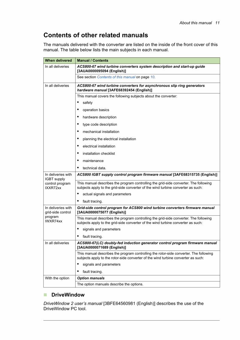
Contents of other related manualsThe manuals delivered with the converter are listed on the inside of the front cover of this manual. The table below lists the main subjects in each manual.
DriveWindow
DriveWindow 2 user’s manual [3BFE64560981 (English)] describes the use of the DriveWindow PC tool.
When delivered Manual / Contents
In all deliveries ACS800-67 wind turbine converters system description and start-up guide [3AUA0000095094 (English)]
See section Contents of this manual on page 10.
In all deliveries ACS800-67 wind turbine converters for asynchronous slip ring generators hardware manual [3AFE68392454 (English)]
This manual covers the following subjects about the converter:
• safety
• operation basics
• hardware description
• type code description
• mechanical installation
• planning the electrical installation
• electrical installation
• installation checklist
• maintenance
• technical data.
In deliveries with IGBT supply control program IXXR72xx
ACS800 IGBT supply control program firmware manual [3AFE68315735 (English)]
This manual describes the program controlling the grid-side converter. The following subjects apply to the grid-side converter of the wind turbine converter as such:
• actual signals and parameters
• fault tracing.
In deliveries with grid-side control program IWXR74xx
Grid-side control program for ACS800 wind turbine converters firmware manual [3AUA0000075077 (English)]
This manual describes the program controlling the grid-side converter. The following subjects apply to the grid-side converter of the wind turbine converter as such:
• signals and parameters
• fault tracing.
In all deliveries ACS800-67(LC) doubly-fed induction generator control program firmware manual [3AUA0000071689 (English)]
This manual describes the program controlling the rotor-side converter. The following subjects apply to the rotor-side converter of the wind turbine converter as such:
• signals and parameters
• fault tracing.
With the option Option manuals
The option manuals describe the options.

12 About this manual
Further informationAddress any inquiries about the product to your local ABB representative, quoting the type code and serial number of the unit. If the local ABB representative can not be contacted, address inquiries to nearest country that has support for wind turbine converters. See detailed contact information from the back cover of this manual.
In case of fault situations, ensure that the information stated below is available to get fast problem solving assistance:• fault logger data
• data logger files (data logger 1 and data logger 2) from grid-side and rotor-side converter control programs
• parameter files from the grid-side and rotor-side converter control programs.
In DriveWindow,• save the parameters with File / Parameters / Save as command to a .dwp file (for
instructions, see page 100)
• copy the fault data from the Fault logger view and paste it to a .txt file
• copy the graphs from the Data logger view.
Terms and abbreviationsSee also ACS800-67 wind turbine converters for asynchronous slip ring generators hardware manual [3AFE68392454 (English)].
Abbreviation Explanation
BAMU Auxiliary measurement unit
DFIG Doubly-fed induction generator
DTC Direct Torque Control
Grid-side converter
A converter that is connected to the electrical power network (grid) and is capable of transferring energy from the converter DC link to the grid and vice versa. The grid-side converter is also called ISU (see ISU).
IGBT Insulated gate bipolar transistor
ISU IGBT supply unit. IGBT supply modules under control of one control board, and related components.
INU Inverter unit. Inverter module(s) under control of one control board, and related components. One INU typically controls one generator.
LVRT Low-voltage ride-through
NAMU Auxiliary Measuring Unit. Performs voltage measurement for RMIO board of the grid-side converter.
NUIM Voltage and Current Measurement Unit. Performs voltage and current measurement for AMC board.
MCB Main circuit breaker
PLC Programmable logic controller
PWM Pulse width modulation
Rotor-side converter
A converter that is connected to the generator rotor and controls its operation. The rotor-side converter is also called INU (see INU).
RUSB USB-DDCS adapter
Wind turbine converter
A converter for controlling AC generators in wind turbine applications.
WTC Wind turbine controller
System description 13
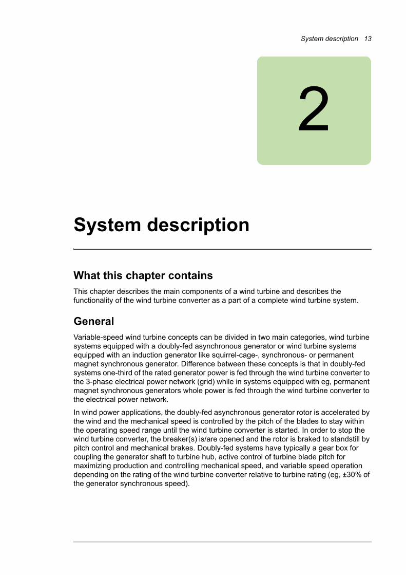
2
System description
What this chapter containsThis chapter describes the main components of a wind turbine and describes the functionality of the wind turbine converter as a part of a complete wind turbine system.
GeneralVariable-speed wind turbine concepts can be divided in two main categories, wind turbine systems equipped with a doubly-fed asynchronous generator or wind turbine systems equipped with an induction generator like squirrel-cage-, synchronous- or permanent magnet synchronous generator. Difference between these concepts is that in doubly-fed systems one-third of the rated generator power is fed through the wind turbine converter to the 3-phase electrical power network (grid) while in systems equipped with eg, permanent magnet synchronous generators whole power is fed through the wind turbine converter to the electrical power network.
In wind power applications, the doubly-fed asynchronous generator rotor is accelerated by the wind and the mechanical speed is controlled by the pitch of the blades to stay within the operating speed range until the wind turbine converter is started. In order to stop the wind turbine converter, the breaker(s) is/are opened and the rotor is braked to standstill by pitch control and mechanical brakes. Doubly-fed systems have typically a gear box for coupling the generator shaft to turbine hub, active control of turbine blade pitch for maximizing production and controlling mechanical speed, and variable speed operation depending on the rating of the wind turbine converter relative to turbine rating (eg, ±30% of the generator synchronous speed).
14 System description
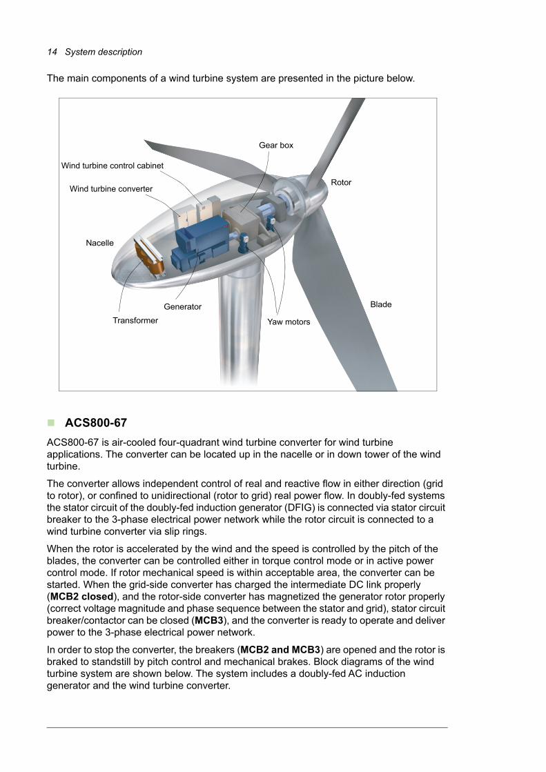
The main components of a wind turbine system are presented in the picture below.
ACS800-67
ACS800-67 is air-cooled four-quadrant wind turbine converter for wind turbine applications. The converter can be located up in the nacelle or in down tower of the wind turbine.
The converter allows independent control of real and reactive flow in either direction (grid to rotor), or confined to unidirectional (rotor to grid) real power flow. In doubly-fed systems the stator circuit of the doubly-fed induction generator (DFIG) is connected via stator circuit breaker to the 3-phase electrical power network while the rotor circuit is connected to a wind turbine converter via slip rings.
When the rotor is accelerated by the wind and the speed is controlled by the pitch of the blades, the converter can be controlled either in torque control mode or in active power control mode. If rotor mechanical speed is within acceptable area, the converter can be started. When the grid-side converter has charged the intermediate DC link properly (MCB2 closed), and the rotor-side converter has magnetized the generator rotor properly (correct voltage magnitude and phase sequence between the stator and grid), stator circuit breaker/contactor can be closed (MCB3), and the converter is ready to operate and deliver power to the 3-phase electrical power network.
In order to stop the converter, the breakers (MCB2 and MCB3) are opened and the rotor is braked to standstill by pitch control and mechanical brakes. Block diagrams of the wind turbine system are shown below. The system includes a doubly-fed AC induction generator and the wind turbine converter.
Transformer
Generator
Yaw motors
Gear box
Blade
Nacelle
Rotor
Wind turbine control cabinet
Wind turbine converter

System description 15
Wind turbine system with low voltage stator (690 V)
Wind turbine system with medium voltage stator (> 1000 V)
No. Description No. Description
1 Rotor hub 10 Low voltage switchgears
2 Blades 11 Medium voltage switchgear
3 Rotor bearing 12 Turbine transformer
4 Gearbox 13 High voltage switchgear
5 Brake system 14 MCB EMERGENCY OPEN CTRL
6 Doubly-fed induction generator 15 MCB CTRL
7 Pitch drive 16 MCB1 ON/OFF CTRL
8 Wind turbine converter 17 MCB3 ON/OFF CTRL
9 Power cabinet
R2
ABRU
R2
ACBU
MCB1MCB3
LCLISU MCB2INU
MCB
WIND TURBINE CTRL
CONVERTER CTRL
1) Optional in ACS800-67
1
2
3
4
5
6
7
8
9
1)
1012 11
14
15
16
17
R2
ABRU
R2
ACBU
MCB3
LCLISU MCB2INU
MCB
CONVERTER CTRL
WIND TURBINE CTRL
1
2
3
4
5
6
7
8
911
12 13
14
15
17

16 System description
Converter system
Doubly-fed asynchronous generators are essentially wound rotor induction machines with variable frequency excitation of the rotor circuit, incorporating rotor via frequency converter. Ability to convert mechanical energy into electrical energy (or vice versa) is based on electromagnetic induction. In wind power applications, the doubly-fed asynchronous generator is controlled to operate as generator quadrature, and thus the generator stator will always generate energy to the 3-phase electrical power network.
Wind turbine converter consists of two parts, ie, rotor-side converter and grid-side converter. Between these two converters, a DC link capacitor is placed as an energy storage in order to keep the voltage variations (or ripple) in the DC link small. Both converters are controlled independently by internal control firmware based on Direct Torque Control (DTC) technology.
The grid-side converter is an IGBT based module equipped with AC (optional) and DC fuses and an LCL filter that suppresses the line harmonics of voltage and current. The grid-side converter is controlled by RDCU-12 control unit with the grid-side control program. The rotor-side converter consists of IGBT based modules and is controlled by NDCU-33CX control unit with the doubly-fed induction generator control program. The control unit also controls the grid-side converter via a fiber optic link.
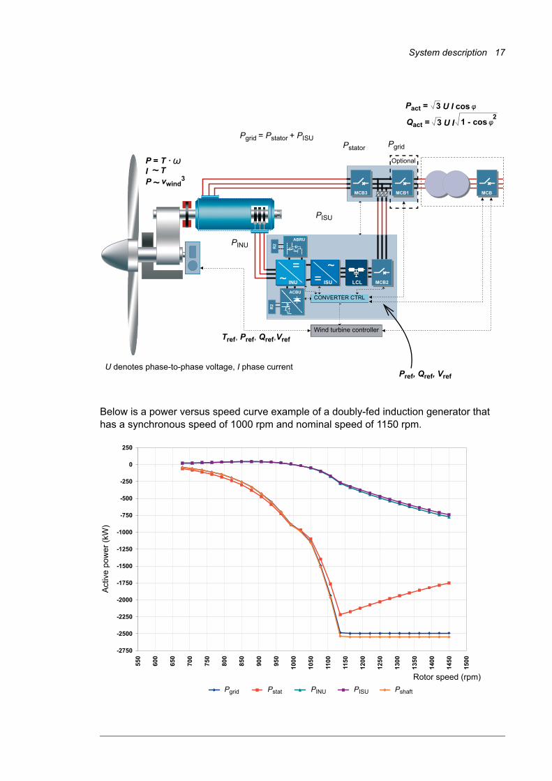
With the rotor-side converter, it is possible to control the torque or the speed of the generator and also the power factor at the stator terminals. The grid-side converter keeps the DC link voltage constant. Wind turbine systems equipped with doubly-fed asynchronous generator, the stator always generates energy to the 3-phase electrical power network, however the direction of the power produced by the rotor depends on the sign of the slip frequency. When the slip frequency is positive (sub-synchronous operation), the energy is taken from the 3-phase electrical power network through the grid-side converter and fed by the rotor-side converter to the rotor via slip rings. In sub-synchronous operation, a part of the stator generated power is circulated back to the rotor. These power flows are shown in the picture below.
System description 17
Below is a power versus speed curve example of a doubly-fed induction generator that has a synchronous speed of 1000 rpm and nominal speed of 1150 rpm.
R2
ABRU
R2
ACBU
MCB1MCB3
LCLISU MCB2INU
MCB
Pstator
Pgrid = Pstator + PISU
PISU
PINU
Wind turbine controller
��P = T · ��
I Tvwind
3P ��
Pref, Qref, Vref
��Pact = U I cos3
��Qact = U I 3 1 - cos2
U denotes phase-to-phase voltage, I phase current
Tref, Pref, Qref,Vref
Pgrid
CONVERTER CTRL
Optional
-2750
-2500
-2250
-2000
-1750
-1500
-1250
-1000
-750
-500
-250
0
250
550
600
650
700
750
800
850
900
950
1000
1050
1100
1150
1200
1250
1300
1350
1400
1450
1500
Act
ive
pow
er (
kW)
Rotor speed (rpm)
Pgrid Pstat PINU PISU Pshaft

18 System description
Control of generator power
The generator power can be controlled by adjusting torque or speed:
where
P generator power (W)
T generator torque (N·m)
angular speed of the generator (rad/s)
n rotor mechanical speed (1/min rpm).
In normal operation, the converter controls the generator torque. However, either a torque or an active power reference to the converter is supported. The overriding wind turbine controller (WTC) gives a torque reference (or an active power reference) to the converter that generates a specific torque on the generator shaft. The overriding wind turbine controller defines the needed torque/power reference as a function of wind speed and turbine characteristics. A typical wind turbine power vs. speed curve is presented below. It illustrates the operational speed range of the turbine between the cut-in and cut-out speeds. Cut-in speed is the minimum wind speed at which power generation is reasonable. Cut-out speed is the maximum operating speed that the wind turbine system can tolerate. In the example below, the generator is for 1700 rpm and 2400 kW.
P = T · = T · ��2 �� · n
60
��
Wind speed (m/s)
0 5 10 15 20 25 30 350
1200
1300
1400
1500
1600
1700
1800
1900
2000
0
400
800
1200
1600
2000
2400
2800
3200
3600
Generator rotor speed (rpm)
Cut-in speed Cut-out speed
Power optimization Power limitation
Turbine power delivered to electrical power network (kW)

System description 19
Operational speed range of a typical wind turbine
Wind power increases cubically as wind speed increases:
where
Pw wind power
air density
cp performance coefficient, tip speed ratio, pitch angle
Ar rotor surface
vw wind speed.
There is a minimum wind speed at which power generation is reasonable (cut-in speed) and a maximum speed at which the turbine can be operated safely (cut-out speed). At a certain wind speed, the turbine controller must limit the rotor speed by changing the pitch angle.
Pw = · Ar · vw3
2��
����cp( , )·
��
�� ��
20 System description
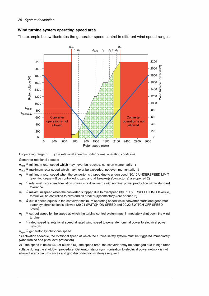
Wind turbine system operating speed area
The example below illustrates the generator speed control in different wind speed ranges.
200
400
600
800
1000
1200
1400
1600
1800
2000
2200
00 300 600 900 1200 1500 1800 2100 2400 2700
200
400
600
800
1000
1200
1400
1600
1800
2000
2200
03000
nmin nmaxn1 nA n3nr n2 nBnsync
Win
d tu
rbin
e po
wer
(kW
)
In operating range n1…n3 the rotational speed is under normal operating conditions.
Generator rotational speeds:
nmin minimum rotor speed which may never be reached, not even momentarily 1)
nmax maximum rotor speed which may never be exceeded, not even momentarily 1)
n1 minimum rotor speed when the converter is tripped due to underspeed (30.10 UNDERSPEED LIMIT level) ie, torque will be controlled to zero and all breaker(s)/contactor(s) are opened 2)
n2 rotational rotor speed deviation upwards or downwards with nominal power production within standard tolerance
n3 maximum speed when the converter is tripped due to overspeed (30.09 OVERSPEED LIMIT level) ie, torque will be controlled to zero and all breaker(s)/contactor(s) are opened 2)
nA cut-in speed equals to the converter minimum operating speed while converter starts and generator stator synchronisation is allowed (20.21 SWITCH ON SPEED and 20.22 SWITCH OFF SPEED levels)
nB cut-out speed ie, the speed at which the turbine control system must immediately shut down the wind turbine
nr rated speed ie, rotational speed at rated wind speed to generate nominal power to electrical power network
nsync generator synchronous speed
1) Activation speed ie, the rotational speed at which the turbine safety system must be triggered immediately (wind turbine and pitch level protection)
2) If the speed is below (n1) or outside (n3) the speed area, the converter may be damaged due to high rotor
voltage during the shutdown procedure. Generator stator synchronisation to electrical power network is not allowed in any circumstances and grid disconnection is always required.
=
=
=
=
=
=
=
=
=
Umax
Converter operation is not
allowed
Rot
or v
olta
ge (
V)
Ucont.max
Rotor speed (rpm)
Converter operation is not
allowed

System description 21
Control of torque and reactive power via rotor-side converter
With DTC technology field orientation is achieved by using advanced generator theory to calculate the accurate generator torque. The performance of DTC controlled wind turbine converter is most effective and benefits are eg, fast torque response, accurate control also at low frequencies, torque repeatability and accuracy of dynamic and static speed operations.
The main difference between DTC and conventional PWM is that the torque is controlled at the same time level as power switches (25 microseconds). There is no separate voltage and frequency controlled PWM modulator. All selections of the switches are based on the electromagnetic state of the generator and torque demand given by turbine control system.
The controlling variables of the DTC are generator magnetizing flux and generator torque. In doubly-fed induction generator systems, the voltage in rotor/stator windings forms the current and magnetic flux by changing the direction of the voltage in rotor windings. The direction of the flux can also be changed. By changing the voltage direction in 3-phase generator rotor windings in the correct order, the magnetic flux of the generator rotor will follow this flux with a certain slip. There are eight different switching positions in the two-level converter that can affect the flux and torque of the generator. In two positions the voltage is zero, ie, when all the phases are connected to the same DC link, either negative or positive. In remaining six switching positions voltage is created in the generator rotor windings creating magnetic flux. In addition, the DTC principle is used to control the power factor at the stator terminals of the doubly-fed induction generator to desired level and to synchronize the stator to the 3-phase electrical power network.
The figure below shows the block diagram of the torque and power factor controller of the doubly-fed asynchronous generator fed from the rotor-side.

22 System description
The basic DTC block selects the inverter switch states so that tangential motion of the flux vector is controlled by the torque error and the radial motion of the flux is controlled by the flux error. The torque reference is supplied by the WTC. The torque feedback is calculated by using stator-side quantities (at grid frequencies) ie, by a cross product of stator flux and stator current.
~ =~ 3~=
RD
CU
ND
CU
Flu
x re
fere
nce
Act
ual f
lux
Pre
f
Torq
ue
re
fere
nce
Act
ua
l to
rque
Hys
tere
sis
ba
nd
con
trol
Tw
o le
vel h
yste
resi
s co
ntro
l
Th
ree
leve
l hys
tere
sis
con
trol
ma
x
ref
min
max
ref
min
Torq
ue
an
d flu
x ca
lcu
latio
n
Torq
ue a
nd
flu
x ca
lcu
latio
n
Flu
x bi
t
Sw
itchi
ng
fre
qu
ency
Torq
ue
bits
AS
IC
AS
IC
Op
timu
m
puls
e
sele
ctor
Op
timu
m
puls
e
sele
ctor
Cu
rre
nt
DC
lin
k vo
ltag
e
Gri
d vo
ltage
Sw
itch
po
sitio
n c
om
ma
nds
Sw
itch
posi
tion
s
NA
MU
/ B
AM
U(o
pti
on
al)
NU
IM
Act
ua
l flu
x
Flu
x re
fere
nce
Act
ual f
lux
Pre
f
Torq
ue
refe
renc
e
Act
ual t
orq
ue
ma
x
ref
min
ma
x
ref
minFlu
x se
ctor
ide
ntif
ica
tion
Hys
tere
sis
ba
nd
con
tro
l
Two
leve
l hys
tere
sis
con
tro
l
Thr
ee
leve
l hys
tere
sis
cont
rol
Flu
x b
it
Sw
itch
ing
fre
qu
enc
y
Torq
ue
bits
Ad
apt
ive
ge
nera
tor
mo
del
Sw
itch
po
sitio
n c
om
ma
nd
s
Sw
itch
posi
tions
DC
lin
k vo
ltag
e
Ro
tor
curr
ent
Act
ua
l flu
x
Act
ual
to
rqu
e
Grid
flu
x
Sta
tor
flux
Sta
tor
curr
ent
Ro
tor
pos
itio
n
LC
L fil
ter
ISU
INU
cro
wba
r
DF
IG
System description 23
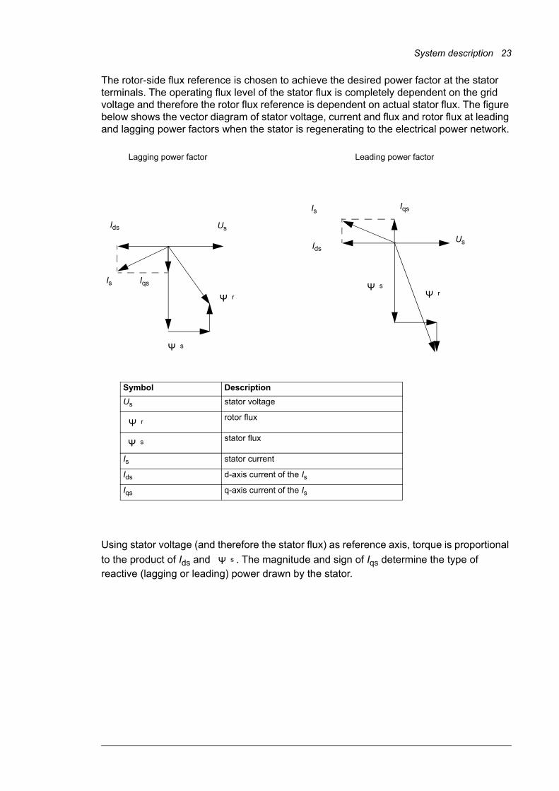
The rotor-side flux reference is chosen to achieve the desired power factor at the stator terminals. The operating flux level of the stator flux is completely dependent on the grid voltage and therefore the rotor flux reference is dependent on actual stator flux. The figure below shows the vector diagram of stator voltage, current and flux and rotor flux at leading and lagging power factors when the stator is regenerating to the electrical power network.
Using stator voltage (and therefore the stator flux) as reference axis, torque is proportional
to the product of Ids and . The magnitude and sign of Iqs determine the type of reactive (lagging or leading) power drawn by the stator.
s
r
Ids Us
Is Iqs
Ids
Is Iqs
Us
s r
Lagging power factor Leading power factor
Symbol Description
Us stator voltage
rotor flux
stator flux
Is stator current
Ids d-axis current of the Is
Iqs q-axis current of the Is
r
s
s

24 System description
An example curve of maximum reactive power capability as a function of the active power (power factor about 0.95 capacitive and 0.86 inductive) is shown below. Reactive power capability depends on the characteristics of the generator.
0.25 0.5 0.75 1.000
0.25
0.5
0.75
0
-0.25
-0.5
-0.75
Converter nominal power
P (p.u.)
Q (p.u.)
Reactivepower
capability atnominal power
-1.00
-1.25
Capacitive
Q (p.u.)
Inductive

System description 25
Control of torque and reactive power via grid-side converter
The fundamental theory of grid-side converter can be simplified to be analog to the synchronous generator. One voltage source is the electrical power network and the other voltage source is the grid-side converter. The voltages and currents can be presented as vectors. When the reactive power is zero, the current vector is in the same direction with the grid voltage vector. In the figure below, the current contains capacitive component, ie, the current is leading the grid-voltage.
The primary function of the grid-side converter is to control the power transfer between the network and the DC link. The control system can be divided into two sections:• Flux controller and torque controller. The flux controller is controlling the length of the
flux vector (flux vector is an integral of the voltage vector) that has influence on the reactive power.
• Torque controller controls the power flow from/to the electrical power network (basically the power transfer angle is controlled). The DC voltage controller gives the reference to the torque controller.
Power transfer equation between the network and the grid-side converter is following:
U1
U2
IX = j L��
u1
iQ
uL
Symbol Description
U1 grid voltage
U2 grid-side converter voltage
angular frequency of the grid
X reactance between U1 and U2
P active power
Q reactive power
I grid-side converter current
angle between U2 and I
��
��
i
iD
u2
P = U1U2
Xsin ��
26 System description
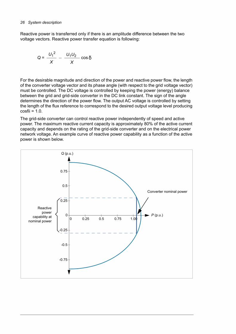
Reactive power is transferred only if there is an amplitude difference between the two voltage vectors. Reactive power transfer equation is following:
For the desirable magnitude and direction of the power and reactive power flow, the length of the converter voltage vector and its phase angle (with respect to the grid voltage vector) must be controlled. The DC voltage is controlled by keeping the power (energy) balance between the grid and grid-side converter in the DC link constant. The sign of the angle determines the direction of the power flow. The output AC voltage is controlled by setting the length of the flux reference to correspond to the desired output voltage level producing cosfii = 1.0.
The grid-side converter can control reactive power independently of speed and active power. The maximum reactive current capacity is approximately 80% of the active current capacity and depends on the rating of the grid-side converter and on the electrical power network voltage. An example curve of reactive power capability as a function of the active power is shown below.
Q = U1
2
Xcos ��
U1U2
X
0.25 0.5 0.75 1.000
0.25
0.5
0.75
0
-0.25
-0.5
-0.75
Converter nominal power
P (p.u.)
Q (p.u.)
Reactivepower
capability atnominal power

System description 27
Overview of converter interfacesThe WTC controls the converter using its main control word. For more information, refer to section ABB Drives communication profile on page 90.
The start-up procedure of the converter is recommended to be proceeded with the DriveWindow PC tool. For information on using the DriveWindow, see DriveWindow 2 user’s manual [3BFE64560981 (English)].
With optional Ethernet adapter module (NETA), the user can remotely • monitor the converter
• read and adjust converter parameter values
• read status information and actual values from the converter
• set up and monitor (numerically or graphically) the data logger and save its content to a file
• read and clear the contents of the fault log and save it to a file
• control the converter (not recommended remotely)
• give control commands (Start, Stop, Run enable, etc.) to the converter
• feed a generator speed or torque reference to the converter
• reset converter faults.
For more information, see NETA-01 Ethernet adapter module user’s manual [3AFE64605062 (English)].

28 System description
Converter control
General
The WTC operates as the overriding controller of the converter. It is connected to the NDCU control unit of the rotor-side converter via fieldbus. The rotor-side converter control program controls the rotor-side power modules according to the references and commands sent by the overriding controller.
PLC interface
The converter can be connected to an external control system – usually a PLC controller – via a fieldbus adapter connected to channel CH0 of the NDCU control unit.
The following diagram shows the PLC interface:
The converter can be set to receive all of its control information through the fieldbus interface, or the control can be distributed between the fieldbus interface and other available sources, eg, digital and analog inputs.
Fieldbus
Otherdevices
PLC
Control Word (CW)References
Data Flow
Status Word (SW)Actual values
Parameter R/W requests/responses
Fieldbus adapter
Process I/O (cyclic)
Service messages (acyclic)
NxxxRDCU
Grid-side converter
NDCU
Rotor-side converter
CH0CH0 CH2
CH3 CH4
NETA-01 (optional)
Turbine intranet (Ethernet)
Otherdevices
WTC
System description 29
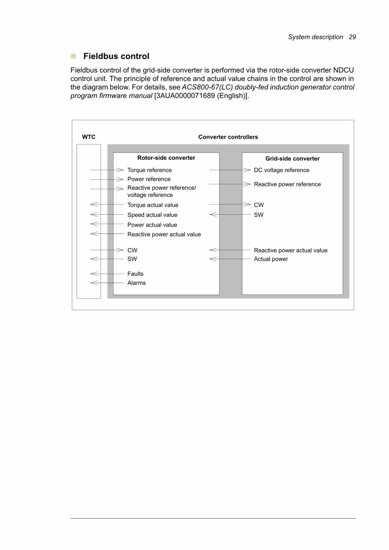
Fieldbus control
Fieldbus control of the grid-side converter is performed via the rotor-side converter NDCU control unit. The principle of reference and actual value chains in the control are shown in the diagram below. For details, see ACS800-67(LC) doubly-fed induction generator control program firmware manual [3AUA0000071689 (English)].
WTC Converter controllers
Rotor-side converter
Reactive power reference/
Power reference
Torque reference
Grid-side converter
Reactive power reference
DC voltage reference
Reactive power actual value
Power actual value
Torque actual value
Reactive power actual value
Actual power
Speed actual value
CW
SW
CW
SW
Faults
Alarms
voltage reference

30 System description
Grid codesGrid codes specify static and dynamic requirements to be fulfilled by a wind power installation. Static requirements mainly determine the voltage control and power control during normal operation. Most of the recent grid codes include also power quality requirements such as harmonics distortion limits, flicker etc. Dynamic requirements define the dynamic behavior of a wind turbine or wind farm under grid disturbance. One of the most important dynamic requirements is grid fault ride-through capability of the wind power generator. Grid fault ride-through means that instead of disconnection, the wind generators have to stay connected to the electrical power network for a certain period. Grid fault ride-through requirements define:• how long a grid fault (eg, voltage dip/sag or swell) can last
• how to operate under a balanced (symmetrical) grid fault
• how to operate under an unbalanced (unsymmetrical) grid fault.
The power train concept can be used to find the optimal solution when balancing the connection requirements and costs of installation. The selection of electrical power train components (a pitch system, generator, frequency converter and transformer) has effect on the capability of an individual turbine to comply with the grid code requirements.
Although the converter has an important role in enabling the wind turbine to fulfill the grid code requirements, it is highly dependent on how the whole wind turbine system and its process is functioning (the wind turbine controller, pitch system, UPS etc.). The turbine manufacturer is responsible for fulfilling the requirements of the transmission or distribution system operator.
Example of grid code regulations in different countries
• REE P.O.12.3 RED ELÉCTRICA DE ESPAÑA P.O.12.3 Fault ride-through capabilities and reactive power/voltage control during faults in wind power installations
• National Grid Electricity Transmission plc
The Grid Code, Issue 4, Revision 4, 18th October 2010
• Technical regulation 3.2.5 for wind power plants with a power output greater than 11 kW
Rev. 4.1. 30.9.2010
• National Grid Code (China) Technical Rule for Connecting Wind farm into Power Network, July 2009
• Transmissioncode 2007 Netz- und Systemregeln der deutschenÜbertragungsnetzbetreiber, August 2007
• transpower stromübertragungs gmbh
Grid Code for high and extra high voltage, 1st April 2009
• transpower stromübertragungs gmbh
Requirements for Offshore Grid Connections in the transpower Grid, 30th April 2010
• 50Hertz Transmission GmbH Netzanschluss- und Netzzugangsregeln, May 2008
• System Service Ordinance Ordinance on System Services by Wind Energy Plants (System Service Ordinance – SDLWindV)
• BDEW Technische Richtlinie Erzeugungsanlagen am Mittelspannungsnetz, Richtlinie für Anschluss und Parallelbetrieb von Erzeugungsanlagen am Mittelspannungsnetz, June 2008
• TR3 Technische Richtlinienfür Erzeugungseinheiten und –anlagen Teil 3 Bestimmung der Elektrischen Eigenschaften von Erzeugungseinheiten am Mittel-, Hoch- und Höchstspannungsnetz;
• 111 FERC 61,252 United States of America, Federal Energy Regulatory Commission, 18 CFR part 35. 2005
• Guida Tecnica Sistemi di controllo e protezione delle centrali eoliche [prescrizioni tecniche per la connessione]

System description 31
Example limit curves
According to this example, electrical power network failure (eg, voltage dip/sag) may not cause instability above the limit line 1 or disconnection of the converter from the grid. The limit curves for voltage at the grid connection in case of a fault in the grid are shown below. U denotes the remaining grid voltage and UN the converter nominal voltage.
Description of parameter settings
The parameter settings of the grid fault ride-through function are described in section Grid support on page 34.
0 t1 Time
0
100
U/UN (%)
Fault occurs
Limit line 1Long-term remaining voltage level after fault clearance
t2 t3
Limit line 2
Ride-through and grid support may be required
Tripping required/allowed
Ride-through required and grid support may be required
Normal operation

32 System description
Grid fault ride-trough capabilityAlthough the advantage of doubly-fed concept is that the size of the wind turbine converter is significantly smaller than full-power converter, the drawback is that the rotor-side converter is a vulnerable part of the system. It has a restricted overcurrent limit and it needs special attention especially during faults in the grid. When faults occur and cause eg, voltage dips or sags, the magnetic flux in the generator can not change instantaneously. As a result sudden change in the stator, supply voltage is followed by a large change in the generator currents. The converter responds to the change of rotor currents so that the rotor currents are maintained as required by the rotor-side converter control.
Since the output voltages and currents of the rotor-side converter are limited, the rotor-side converter may not be able to maintain the rotor currents within given limits during severe grid faults and thus it must be protected. Wind turbine converter can be equipped with hardware-based protection device, a crowbar. The crowbar is used to protect the converter in case of unexpected electrical power network failure. There are two types of crowbars, a passive crowbar that does not allow the grid fault ride-through function, and an active crowbar that allows to operate through pre-determined electrical power network failure without tripping (grid fault ride-through operation).
The crowbar consists of the crowbar unit and a high power resistor. The active crowbar is controlled by the rotor-side converter control firmware, and in case of failure, it can protect the converter independently. The crowbar is triggered if DC link voltage is too high or alternatively if the rotor current is too high.
Grid codes typically require that the wind turbine must remain connected to the grid under different kinds of grid failure events (eg, voltage dip/sag, short interruption, swell etc). It is very common that the wind turbine• has to stay connected to the power system for a certain period
• may not take power from the power system
• produces capacitive reactive current.
Wind turbine converter can be equipped with a DC chopper for DC link power dissipation. The DC chopper may be needed if grid fault ride-through or high swell threshold is required. The DC chopper is connected to the DC link and it operates independently always when DC link voltage rises above its triggering level. A diagram of the wind turbine system with the DC chopper is shown below.

System description 33
With the crowbar and the DC chopper, the wind turbine is capable of handling fault situations like rotor overspeed, short interruptions, voltage dips/sags and swells. With these energy absorbers, the converter is capable of meeting even the most strictest grid fault ride-through requirements in accordance with international grid codes.
R2
ABRU
R2
ACBU
MCB1MCB3
LCLISU MCB2INU
MCB
WIND TURBINE CTRL
CONVERTER CTRL
DC chopper (optional)
Optional
34 System description
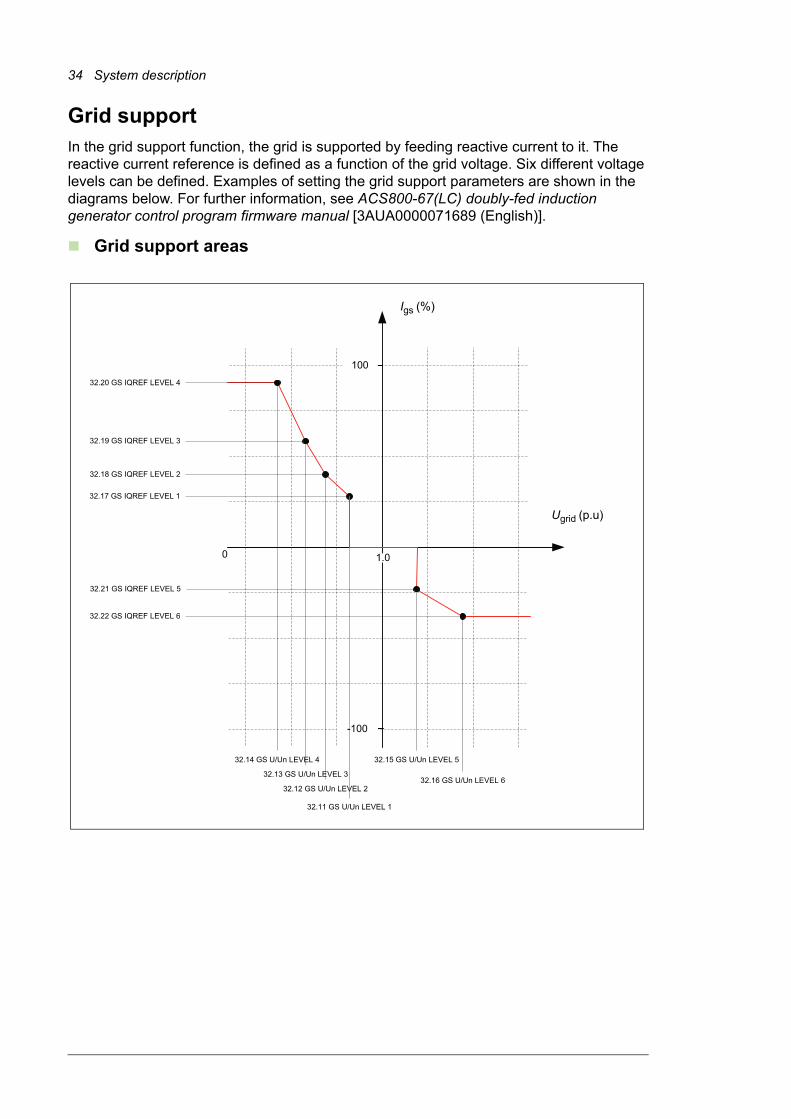
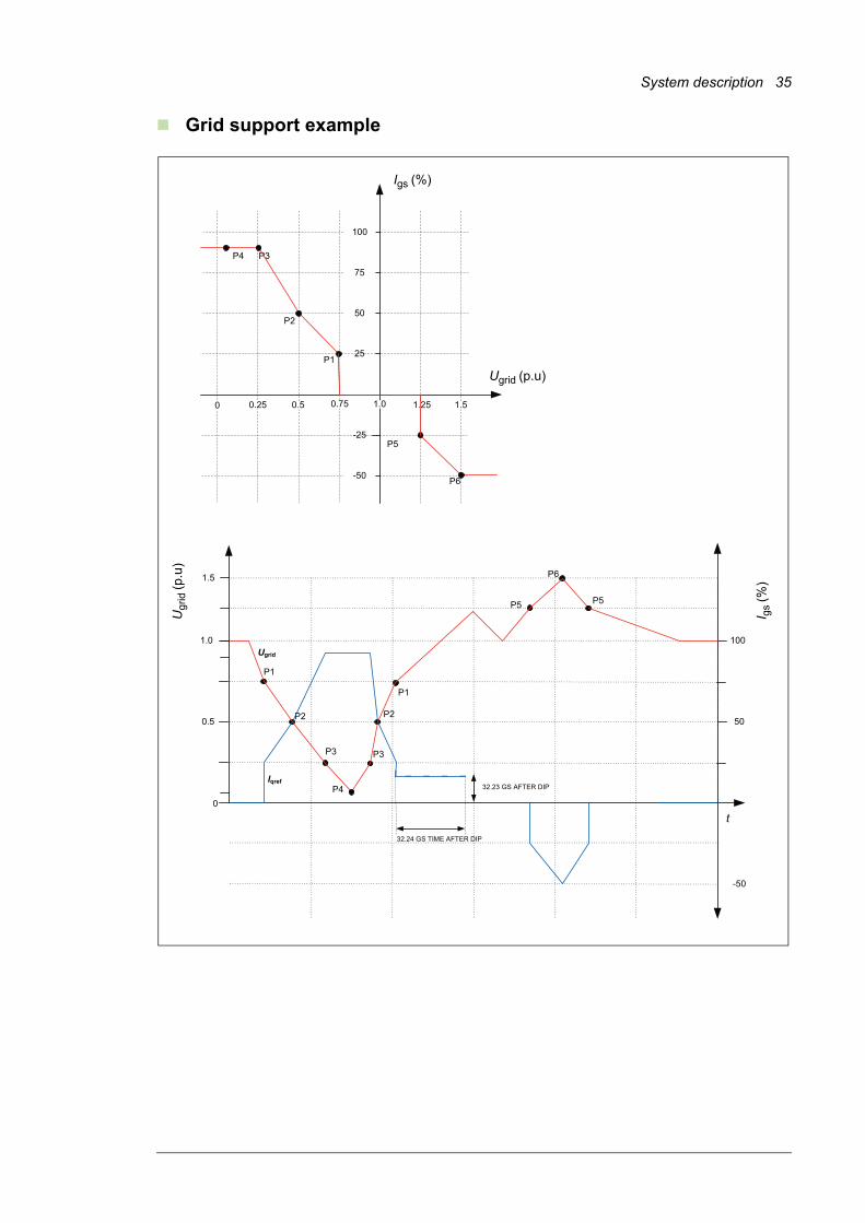
Grid supportIn the grid support function, the grid is supported by feeding reactive current to it. The reactive current reference is defined as a function of the grid voltage. Six different voltage levels can be defined. Examples of setting the grid support parameters are shown in the diagrams below. For further information, see ACS800-67(LC) doubly-fed induction generator control program firmware manual [3AUA0000071689 (English)].
Grid support areas
-100
100
0 1.0
32.21 GS IQREF LEVEL 5
32.17 GS IQREF LEVEL 1
32.18 GS IQREF LEVEL 2
32.19 GS IQREF LEVEL 3
32.20 GS IQREF LEVEL 4
32.14 GS U/Un LEVEL 4
32.13 GS U/Un LEVEL 3
32.12 GS U/Un LEVEL 2
32.11 GS U/Un LEVEL 1
32.15 GS U/Un LEVEL 5
32.22 GS IQREF LEVEL 6
32.16 GS U/Un LEVEL 6
Ugrid (p.u)
Igs (%)
System description 35
Grid support example
P2
P3P4
P5
P6
P1
-25
25
100
0 0.75
75
50
-50
1.51.251.00.50.25
P5
P6
P4
P2
P1
P1
P2
P3
1.0
0
t
0.5
100
50
Ugrid
Iqref
1.5
P3
-50
P5
32.24 GS TIME AFTER DIP
32.23 GS AFTER DIP
Ugrid (p.u)
Igs (%)
I gs
(%)
Ugr
id (p
.u)
36 System description
Stator circuit connection to gridThe converter can control both breaker and contactor for connecting the generator stator to the grid. The main difference between these configurations is that if the stator circuit is equipped with a breaker, it allows disconnecting the stator from the grid even with a high stator current. When the stator circuit is equipped with a contactor, disconnecting the stator from the grid must be handled selectively. If the stator contactor is opened under high current, it may be damaged.
Selective disconnection from the grid is handled so that any time the stator contactor is commanded to open, instantaneous stator current is compared to the given limit. If stator current is below the limit, the stator contactor is opened. Conversely, if stator current is above the limit, the stator contactor is kept closed and the grid-side breaker (MCB1, optional) is opened instead; the stator contactor is opened after a certain delay.
The hardware connection type for the grid connection is defined by parameter 16.20 GRID CONNECT MODE. For the time schemes of the grid connection signals and operation of digital inputs and outputs, see ACS800-67(LC) doubly-fed induction generator control program firmware manual [3AUA0000071689 (English)]. The differences between the configurations are presented below.
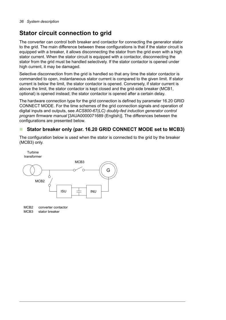
Stator breaker only (par. 16.20 GRID CONNECT MODE set to MCB3)
The configuration below is used when the stator is connected to the grid by the breaker (MCB3) only.
ISU INU
G
MCB3
MCB2
Turbine transformer
MCB2 converter contactorMCB3 stator breaker

System description 37
Main circuit breaker (par. 16.20 GRID CONNECT MODE set to MCB1+MCB3/A)
The configuration below is used when the concept contains an optional grid-side breaker (MCB1).
Main circuit breaker (par. 16.20 GRID CONNECT MODE set to MCB1+MCB3/B)
The configuration below is used when the concept contains an optional grid-side breaker (MCB1). DO/DI connections differ from selection MCB1+MCB3/A.
ISU INU
G
MCB1 MCB3
MCB2
Turbine transformer
MCB1 main breakerMCB2 converter contactorMCB3 stator contactor
ISU INU
G
MCB1 MCB3
MCB2
Turbine transformer
MCB1 main breakerMCB2 converter contactorMCB3 stator contactor

38 System description
Stator contactor (par. 16.20 GRID CONNECT MODE set to MCB1+MCB3/C)
The configuration below is used when MCB1 and MCB3 are connected in series.
The breaking device type for the grid connection is defined by parameter 20.27 CONT OPEN CUR.• 0 A = main circuit breaker or medium voltage circuit breaker MCB3 is used for
disconnecting stator from grid
• > 0 A = contactor MCB3 is used for disconnecting stator from grid.
When parameter value [> 0 A] is selected, the converter can be disconnected from the grid in two ways depending on a parameter setting:• If measured current 06.29 STATOR IS NO FILT is below the parameter value, the
converter uses the stator contactor only.
• If measured current 06.29 STATOR IS NO FILT is above the parameter value, the converter first opens the breaker and, after a short time, the stator contactor.
The parameter value is compared to unfiltered stator rms value. Since the unfiltered value always contains a certain amount of noise, it is recommended to set the parameter to a value of contactor nominal current +15%. See the delivery specific circuit diagrams.
Settings
Parameter 20.27 CONT OPEN CUR.
In case of one contactor, the value for parameter 20.27 CONT OPEN CUR is the nominal current of the contactor.
ISU INU
G
MCB1 MCB3
MCB2
Turbine transformer
MCB1 stator breakerMCB2 converter contactorMCB3 stator contactor

System description 39
Grid connection procedure
A typical procedure required to connect the wind generator to the grid is as follows:• The system is operational if the rotor speed is in the predetermined normal operating
range (eg, from 70% to 130% of the synchronous speed).
• MCB2 is closed to start the converter and to establish the DC link for the rotor-side converter. MCB3 is still open.
• The rotor-side converter measures the grid voltage (input side of MCB3) and the stator voltage.
• The rotor-side converter shifts to synchronization mode. The rotor-side converter magnetizes the rotor windings so that the induced stator voltage is synchronized with the grid voltage (same frequency and magnitude as for the grid voltage).
• MCB3 is closed and the controller shifts to the torque control mode. Now it is ready to accept the user's torque and power factor (pf) commands. The net power generated to the grid (from the stator port + the rotor port) is relative to the product of the torque and the mechanical speed.
The normal shut-down procedure is as follows:• The system is assumed to be in the torque control mode and the rotor speed in the
predetermined normal operating range (eg, from 70% to 130% of the synchronous speed).
• After receiving the shut-down command, converter program sets the rotor-side converter torque reference to zero and power factor command to 1. (Under these conditions the stator current is zero.)
• MCB3 is opened when the converter detects 0 voltage and 0 current across it.
• The rotor-side converter and then the grid-side converter modulation is stopped.
ISU INU
G
MCB3
MCB2
Turbine transformer

40 System description
Phasing checks executed at start-upDuring the encoder calibration and voltage synchronization, the software ensures that the grid, encoder, stator and rotor phasings are correct. The U-phase (and V- and W-phase) of the grid is connect to the U-phase of the stator via main circuit breaker.
The following checks are automatically executed at start-up in the order in which they are listed:
Grid phasing
Grid flux is a measured quantity. The angle of the flux is calculated. The angle is derivated and filtered. As a result, angular speed of the grid flux is received. If the speed is negative, the grid phasing is incorrect.
Encoder phasing
The generator actual speed is received from the encoder speed feedback. If the direction is negative, the encoder phasing is wrong.
Note: This check is executed only if RUN command has been issued.
Stator phasing
During normal operation, the grid flux and the stator flux rotate clockwise at the grid frequency. If the sum of the rotor flux speed and slip does not rotate at the frequency of the stator flux, the stator phasing is incorrect.
Note: The rotation speed of the rotor flux is independent of whether the rotor phasing is correct or not.
Rotor phasing
The dot product between the two flux vectors is approximately +1 when the rotor phasing is correct and approximately -1 when the rotor phasing is incorrect.
StatorGrid
Main circuit breaker
UV WU WVNUIM-6x
Commissioning phasing requirement

Start-up with low voltage stator 41
3
Start-up with low voltage stator
What this chapter containsThis chapter describes the basic start-up procedure of the wind turbine converter equipped with doubly-fed induction generator control program.
Note: Grid-side converters are delivered with one of the following grid voltage measurement methods:• The grid-side converter receives the voltage measurement data from the rotor-side
converter. (The rotor-side converter is only fitted with an NUIM board.)
• The grid-side converter is fitted with a dedicated measurement board, NAMU / BAMU.
Each method requires a different grid-side converter control program version. The first method requires version IXXR7260 with Adaptive program version IZXX0169.AP (or later versions) while the second requires version IWXR7300 with Adaptive program version 00595631_C.AP (or later versions).
The grid-side converter parameter settings in the start-up procedure below differ depending on which grid voltage measurement method is used.
ISU INU
G
Stator breaker

42 Start-up with low voltage stator
How to start-up the converterIn the start-up procedure presented here, the converter is operated locally from DriveWindow PC tool. For instruction on how to operate DriveWindow PC tool, see DriveWindow Online Help or DriveWindow 2 user’s manual [3AFE64560981 (English)].
The start-up mainly uses rotor-side converter parameters. When grid-side converter parameters are needed, a reference to the grid-side converter parameter list in ACS800-67(LC) doubly-fed induction generator control program firmware manual [3AUA0000071689 (English)] is given.
After the first start-up, the converter can be powered up without using these start-up functions. The start-up procedure can be repeated later if start-up data needs to be changed.
WARNING! The generator may not be connected to the grid when the rotor is not rotating. The rotor speed must be in the operational speed area (normally 70…130% of the generator nominal speed). Otherwise grid connection is not
allowed by the converter control program.
Note: For testing purposes the rotor-side converter can be started without closing the stator breaker at zero speed. Note that the control program is not able to execute the commissioning check routines at zero speed. The grid-side converter can be tested even though the generator is not rotating.
Before you start, ensure you have the generator data sheet on hand.
Safety
The start-up may only be carried out by a qualified electrician.
The safety instructions must be followed during the start-up procedure. See ACS800-67 wind turbine converters for asynchronous slip ring generators hardware manual [3AFE68392454
(English)].
Check the installation. See the installation checklist in the converter hardware manual.
Power-up
Connect fibre optic cables temporarily between channel CH3 of the rotor-side converter NDCU unit and the DDCS Communication (RUSB-02) card or PCMCIA card.
If an active crowbar is in use (optional), the crowbar test requires communication with the NDCU unit of the rotor-side converter and RDCU unit of the grid-side converter: Connect the fibre optic cables in a ring connection between channel CH3 of the NDCU unit and channel CH3 of the RMIO board and the DDCS Communication (RUSB-02) card or PCMCIA card.
When a PCMCIA card is used, follow the instructions included in the DriveWindow kit.
Apply main power.
Start the DriveWindow program.
Switch the rotor-side converter to local control mode.
Manual start-up data entering
Upload the parameter and signal lists.

Start-up with low voltage stator 43
Enter the generator data from the generator data sheet. For more information, see section Generator data on page 81.
• generator nominal voltage (U1) 99.02 MOTOR NOM VOLTAGE
• generator nominal stator-side current (I1) 99.03 MOTOR NOM CURRENT
• generator nominal frequency 99.04 MOTOR NOM FREQ
• generator nominal speed 99.05 MOTOR NOM SPEED
• generator nominal power
Note: Generator values must be given at 50 Hz (60 Hz). Calculate generator nominal power with the following equation:
99.06 MOTOR NOM POWER
• generator power factor (cos) 99.12 MOTOR NOM COSFII
• generator synchronous speed 99.14 MOTOR SYNC SPEED
• open-circuit voltage of the rotor (U2) 99.15 MOTOR OPEN CKT V
• maximum allowed long time rotor current limit (for reactive power supervision) IM
99.16 MOTOR NOM IM
• resistances and reactances of the generator equivalent circuit.
Mutual inductance 99.24 Xm is calculated with the following equation:
E = stator voltage without losses (on the generator data sheet)U = stator voltage (on the generator name plate).
The rotor resistance 99.25 Rr (R2PH on the ABB generator
equivalent circuit data) reduced to the stator reference frame is calculated with the following equation:
Note: Some generator manufacturers give equivalent circuit data for delta connection. In that case the given reactance values must be divided by three.
99.21 Rs
99.22 XIS
99.23 X2S
99.24 XM
99.25 Rr
• maximum measurable stator flux. See section Stator current and voltage measurement on page 79.
99.27 MAX MEAS FLUX
Define the maximum measurable stator current (depends on the used current transformer). See section Stator current and voltage measurement on page 79.
99.28 MAX MEAS IS
99.06 MOTOR NOM POWER 99.05 MOTOR NOM SPEED Wind turbine nom. power⋅Wind turbine nom. speed
----------------------------------------------------------------------------------------------------------------------------------------------------=
Xm
EU---- U1⋅
3 Im⋅------------------=
RrR2PH
U2U1-------- 2------------------=

44 Start-up with low voltage stator
Enter the number of encoder pulses. 50.04 PULSE NR
Select the communication profile used by the converter. For more information see section ABB Drives communication profile on page 90.
16.11 COMM PROFILE
Set parameter limits in group 20 LIMITS according to the process requirements.
20.05 USER POS TORQ LIM defines the motoring torque limit 20.06 USER NEG TORQ LIM defines the generating torque limit.
20.05 USER POS TORQ LIM
20.06 USER NEG TORQ LIM
20.21 SWITCH ON SPEED
20.22 SWITCH OFF SPEED
Select the reactive power reference type (PERCENT/KVAR/PHII/COSPHII).
23.04 REACT POW REF SEL
Set the stator overcurrent trip limit.
During commissioning when the converter runs in local control mode without torque references, set parameter value to approximately 500 A. After commissioning set parameter value to 0 A.
30.04 STATOR CURR TRIP
Set the over/underspeed limits. 30.09 OVERSPEED LIMIT
30.10 UNDERSPEED LIMIT
Activate the external communication by setting parameter 98.02 COMM MODULE to FBA DSET 10.
98.02 COMM MODULE
Set the fieldbus adapter data according to the used external control system.
Note: The configuration parameters are not visible if the module is not connected or activated in the control program. See appropriate adapter hardware manual.
51 MASTER ADAPTER
Activate the fieldbus adapter supervision toggle bit (if needed). 70.25 TOGGLE BIT SEL
70.26 TOGGLE ADDRESS SEL
Define the current limit and breaking device type for the grid connection between stator and grid.
0 A = air circuit breaker used for disconnecting stator from grid.
> 0 A = contactor is used for disconnecting stator from grid.
If stator current exceeds given value at the time disconnection is requested, then the wind turbine converter first opens the breaker in front of the contactor, then the contactor shortly later.
20.27 CONT OPEN CUR
Check that the breaker/contactor configuration of the converter is set correctly according to the delivery. For configurations available and corresponding parameter settings, see section Stator circuit connection to grid on page 36.
16.20 GRID CONNECT MODE
If the parameter 16.20 GRID CONNECT MODE selection is MCB1+MCB3/C: To set certain breaker related fault logger texts correctly, set parameter 99.01 LANGUAGE to DEUTSCH.
99.01 LANGUAGE

Start-up with low voltage stator 45
Time setting
Set rotor-side converter 16.01 PARAM LOCK to OFF.
Set the date and time as follows:
• Set parameter 95.07 RTC MODE value to SET.
• Check/adjust the date and time by parameters 95.01…95.06.
• Set parameter 95.07 RTC MODE value to SHOW.
16.01 PARAM LOCK
95.07 RTC MODE
95.01…95.06
Digital inputs
Check that all digital inputs are connected properly. 01.15 DI STATUS
Grid-side converter and crowbar test
Communication between the grid-side converter and the rotor-side converter is checked by controlling the grid-side converter unit via the rotor-side converter unit parameters.
Set parameter 21.01 ISU LOCAL CTR WORD to 9 (hex), ie, 1001 (bin): Grid-side converter starts charging the DC capacitors, closes the main contactor and starts modulating.
21.01 ISU LOCAL CTR WORD
Check the grid-side converter status. Note: Only the three least significant bits are relevant in this case.
231H (1000110001 bin) before the grid-side converter is started
737H (11100110111 bin) when the grid-side converter is running
238H (1000111000 bin) when the grid-side converter has tripped on a fault.
05.10 ISU STATUS WORD
Check that the DC link is charged. 01.10 DC VOLTAGE
Check that the Voltage and Current Measurement Unit NUIM-6x functions, ie, the grid frequency is positive and the grid voltage is correct.
01.05 NET FREQUENCY
01.11 MAINS VOLTAGE
Stop the grid-side converter by setting parameter 21.01 ISU LOCAL CTR WORD to 0 (hex).
21.01 ISU LOCAL CTR WORD
Check the functioning of the crowbar by starting and stopping the grid-side converter. (Parameter 21.01 ISU LOCAL CTR WORD setting 9 (hex) = START and 0 (hex) = STOP)
When DC voltage is 0 V, 01.15 DI STATUS bit 4 value must be 0 (ie, crowbar inactive). 01.15 DI STATUS = 1303 (hex)When DC voltage exceeds 100 V, 01.15 DI STATUS bit 4 value must be 1 (ie, crowbar active). 01.15 DI STATUS = 1713 (hex)
01.15 DI STATUS
If the converter is NOT equipped with an active crowbar, continue to the next section.
Activate the active crowbar by setting rotor-side converter parameter 31.01 CROWBAR HW TYPE according to the type of active crowbar in use.
Note: If the converter is equipped with an active crowbar, it must always be activated by parameter 31.01 even when low voltage ride through (LVRT) and / or grid support is not used.
31.01 CROWBAR HW TYPE
Start the grid-side converter by setting parameter 21.01 ISU LOCAL CTR WORD to 9 (hex).
21.01 ISU LOCAL CTR WORD
Check the communication between the rotor-side converter and the active crowbar:The communication is OK if the temperature of the crowbar is about 25…40 °C and the converter does not trip for crowbar communication time-out.
06.13 CB IGBT TEMP

46 Start-up with low voltage stator
NUIM board in use (grid-side converter control program IXXR72xx):
• Enable the grid-side converter parameter lock by setting parameter 16.03 PASS CODE to 2303. Parameter groups 100…202 become visible when the parameter lock is enabled.
16.03 PASS CODE
NAMU / BAMU board in use (grid-side converter control program IWXR74xx):
• Parameter groups needed are visible automatically.
Check grid-side converter supply voltage measurement:
NUIM board in use (grid-side converter control program IXXR72xx):
• Set grid-side converter parameter 138.04 CASCADE MEAS ENA to ON and
• Set grid-side converter parameter 138.01 NAMU BOARD ENABLE to OFF.
See grid-side converter parameter list:
138.04 CASCADE MEAS ENA
138.01 NAMU BOARD ENABLE
NAMU / BAMU board in use (grid-side converter control program IWXR74xx):
• Set grid-side converter parameter 40.04 PHASE MEAS ENA to OFF and
• Set grid-side converter parameter 40.02 NAMU BOARD ENABLE to ON if NAMU board is in use.
• Set grid-side converter parameter 40.03 BAMU BOARD ENABLE to ON if BAMU board is in use.
40.04 PHASE MEAS ENA
40.02 NAMU BOARD ENABLE
NUIM board in use (grid-side converter control program IXXR72xx):
Check grid-side converter parameter 01.11 MAINS VOLTAGE value (= mains voltage received from the rotor-side converter). If the voltage level is correct, communication between rotor-side and grid-side converters is OK.
01.11 MAINS VOLTAGE
NAMU / BAMU board in use (grid-side converter control program IWXR74xx):
Check grid-side converter parameter 01.11 MAINS VOLTAGE value (= mains voltage received from the rotor-side converter). If the voltage level is correct, measurement is OK.

Start-up with low voltage stator 47
Check grid-side converter mains voltage measurement phase sequence:
Monitor the following grid-side converter signals with DriveWindow datalogger with 1 ms time level, when grid-side converter is started:
NUIM board in use (grid-side converter control program IXXR72xx):138.02 FLUX X NET ACT138.03 FLUX Y NET ACT161.04 FLUX X ACT161.05 FLUX Y ACT
Start DriveWindow datalogger and trigger manually. Upload datalogger information:
If parameter 138.02 FLUX X NET ACT and 161.04 FLUX X ACT signals are in phase and parameter 138.03 FLUX Y NET ACT and 161.05 FLUX Y ACT signals are in phase, the flux measurement is OK.
See grid-side converter parameter list:
16.03 PASS CODE
138.02 FLUX X NET ACT
138.03 FLUX Y NET ACT
161.04 FLUX X ACT
161.05 FLUX Y ACT
NAMU / BAMU board in use (grid-side converter control program IWXR74xx):
02.22 FLUX X NET ACT02.23 FLUX Y NET ACT02.20 FLUX X ACT02.21 FLUX Y ACT
Start DriveWindow datalogger and trigger manually. Upload datalogger information:
If parameter 02.22 FLUX X NET ACT and 02.20 FLUX X ACT signals are in phase and parameter 02.23 FLUX Y NET ACT and 02.21 FLUX Y ACT signals are in phase, the flux measurement is OK.
Note: If this test fails, grid-side converter grid voltage cabling must be checked. See the converter hardware manual.
02.22 FLUX X NET ACT
02.23 FLUX Y NET ACT
02.20 FLUX X ACT
02.21 FLUX Y ACT
Check the grid-side converter parameters. See the grid-side converter parameter list in ACS800-67(LC) doubly-fed induction generator control program firmware manual [3AUA0000071689 (English)].
Stop the grid-side converter by setting parameter 21.01 ISU LOCAL CTR WORD to 0.
Check the grid-side converter parameters. See the grid-side converter parameter list in ACS800-67(LC) doubly-fed induction generator control program firmware manual [3AUA0000071689 (English)].
21.01 ISU LOCAL CTR WORD
Disable the main circuit breaker function by setting parameter 21.02 DISABLE MCB CLOSE to YES (the rotor-side converter synchronizes to the grid but does not close the main circuit breaker).
21.02 DISABLE MCB CLOSE
Start the converter with zero speed with the DriveWindow START button.
Check crowbar measurements after the DC link has been charged:
Measurements are OK, if parameter 06.11 CB BRIDGE VOLTAGE and 06.12 CB IGBT VOLTAGE values are higher than the DC link voltage (01.10 DC VOLTAGE) and parameter 06.13 CB IGBT TEMP value is approximately 25…40 °C.
06.11 CB BRIDGE VOLTAGE
06.12 CB IGBT VOLTAGE
06.13 CB IGBT TEMP
Stop the converter with the DriveWindow STOP button.

48 Start-up with low voltage stator
Test active crowbar functioning with manual trigger:
Select parameter 06.11 CB BRIDGE VOLTAGE and 06.12 CB IGBT VOLTAGE signals to be monitored with DriveWindow datalogger 2.
Use the following DriveWindow settings:
• Interval = 2
• Trigg Conditions = Level, Falling edge
• Trig Variable = 06.11 CB BRIDGE VOLTAGE
• Trigg Level = 700
Start the rotor-side converter in local mode with the DriveWindow START button. (Rotor does not need to rotate.)
Start the DriveWindow datalogger after the DC link has been charged.
Set parameter 21.08 MANUAL TRIGGER first to OFF and then to ON.
Note: 16.01 PARAM LOCK must be set OFF in order to accept command.
Upload datalogger.
If the measured diode bridge voltage (06.11 CB BRIDGE VOLTAGE) drops for a short time when triggered, the active crowbar functions.
06.11 CB BRIDGE VOLTAGE
06.12 CB IGBT VOLTAGE
21.08 MANUAL TRIGGER
The following figure shows the active crowbar voltages when manual triggering is used.
Stop the converter with the DriveWindow STOP button.
Set the Low Voltage Ride Through function and Grid Support function parameters. Values must be set according to the selected grid code. See ACS800-67(LC) doubly-fed induction generator control program firmware manual [3AUA0000071689 (English)].
Grid support function can be tuned by parameters in group 32 LV RIDE-THROUGH.
Grid-side converter and DC chopper test
If the converter is NOT equipped with a DC chopper, continue to the next section.
NUIM board in use (grid-side converter control program IXXR72xx):
• Set parameter 58.01 ADAPT PROG CMD to STOP. (grid-side converter par.)
58.01 ADAPT PROG CMD
NAMU / BAMU board in use (grid-side converter control program IWXR74xx):
• Set parameter 58.01 ADAPT PROG CMD to STOP. (grid-side converter par.)
58.01 ADAPT PROG CMD
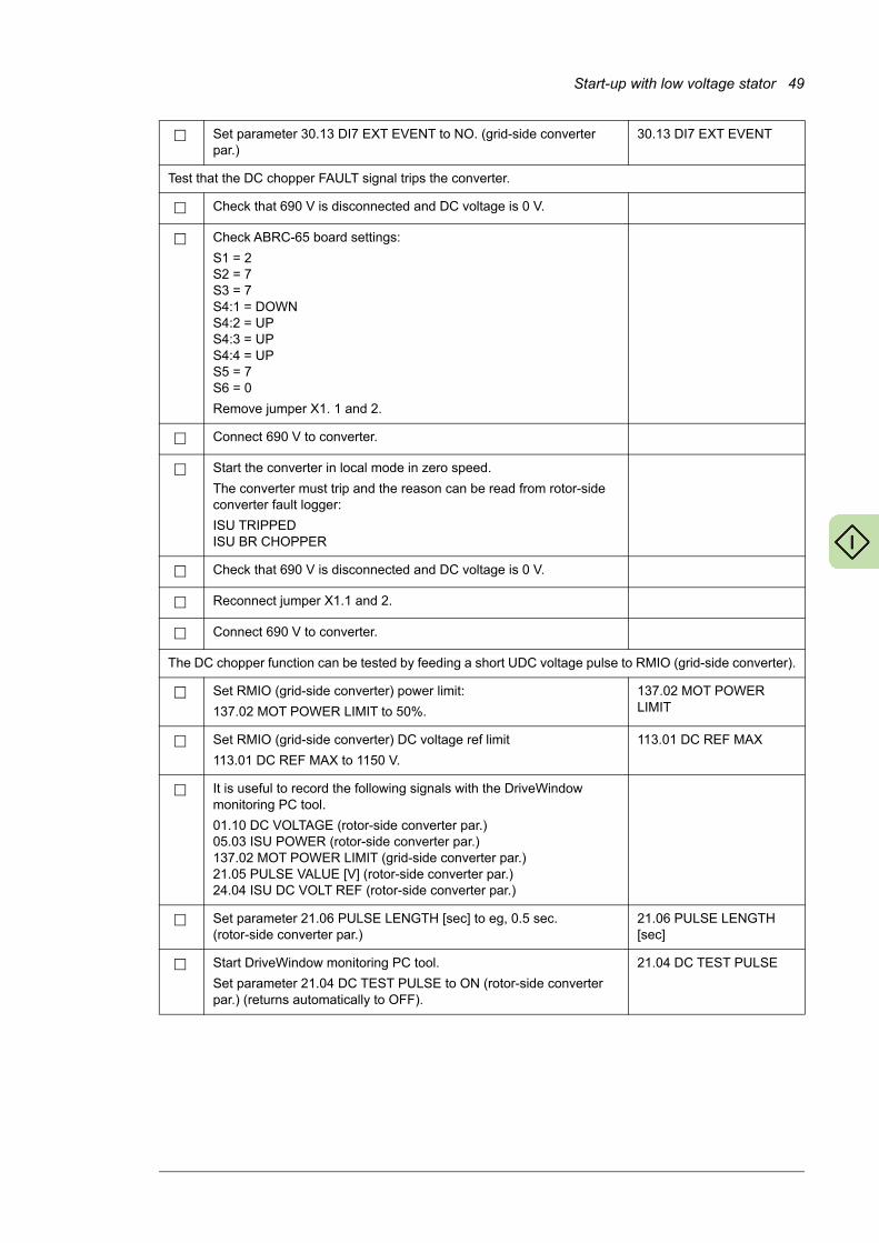
Start-up with low voltage stator 49
Set parameter 30.13 DI7 EXT EVENT to NO. (grid-side converter par.)
30.13 DI7 EXT EVENT
Test that the DC chopper FAULT signal trips the converter.
Check that 690 V is disconnected and DC voltage is 0 V.
Check ABRC-65 board settings:
S1 = 2S2 = 7S3 = 7S4:1 = DOWNS4:2 = UPS4:3 = UPS4:4 = UPS5 = 7S6 = 0
Remove jumper X1. 1 and 2.
Connect 690 V to converter.
Start the converter in local mode in zero speed.
The converter must trip and the reason can be read from rotor-side converter fault logger:
ISU TRIPPEDISU BR CHOPPER
Check that 690 V is disconnected and DC voltage is 0 V.
Reconnect jumper X1.1 and 2.
Connect 690 V to converter.
The DC chopper function can be tested by feeding a short UDC voltage pulse to RMIO (grid-side converter).
Set RMIO (grid-side converter) power limit:
137.02 MOT POWER LIMIT to 50%.
137.02 MOT POWER LIMIT
Set RMIO (grid-side converter) DC voltage ref limit
113.01 DC REF MAX to 1150 V.
113.01 DC REF MAX
It is useful to record the following signals with the DriveWindow monitoring PC tool.
01.10 DC VOLTAGE (rotor-side converter par.)05.03 ISU POWER (rotor-side converter par.)137.02 MOT POWER LIMIT (grid-side converter par.)21.05 PULSE VALUE [V] (rotor-side converter par.)24.04 ISU DC VOLT REF (rotor-side converter par.)
Set parameter 21.06 PULSE LENGTH [sec] to eg, 0.5 sec. (rotor-side converter par.)
21.06 PULSE LENGTH [sec]
Start DriveWindow monitoring PC tool.
Set parameter 21.04 DC TEST PULSE to ON (rotor-side converter par.) (returns automatically to OFF).
21.04 DC TEST PULSE
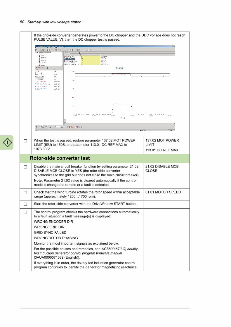
50 Start-up with low voltage stator
If the grid-side converter generates power to the DC chopper and the UDC voltage does not reach PULSE VALUE [V], then the DC chopper test is passed.
When the test is passed, restore parameter 137.02 MOT POWER LIMIT (ISU) to 150% and parameter 113.01 DC REF MAX to 1073.39 V.
137.02 MOT POWER LIMIT
113.01 DC REF MAX
Rotor-side converter test
Disable the main circuit breaker function by setting parameter 21.02 DISABLE MCB CLOSE to YES (the rotor-side converter synchronizes to the grid but does not close the main circuit breaker).
Note: Parameter 21.02 value is cleared automatically if the control mode is changed to remote or a fault is detected.
21.02 DISABLE MCB CLOSE
Check that the wind turbine rotates the rotor speed within acceptable range (approximately 1200…1700 rpm).
01.01 MOTOR SPEED
Start the rotor-side converter with the DriveWindow START button.
The control program checks the hardware connections automatically. In a fault situation a fault message(s) is displayed:
WRONG ENCODER DIR
WRONG GRID DIR
GRID SYNC FAILED
WRONG ROTOR PHASING
Monitor the most important signals as explained below.
For the possible causes and remedies, see ACS800-67(LC) doubly-fed induction generator control program firmware manual [3AUA0000071689 (English)].
If everything is in order, the doubly-fed induction generator control program continues to identify the generator magnetizing reactance.
�

Start-up with low voltage stator 51
It is useful to record important signals with the DriveWindow monitoring PC tool.
01.01 MOTOR SPEED [rpm]
01.10 DC VOLTAGE [V]
01.11 MAINS VOLTAGE [V]
02.01 STATOR IS [RMS]
02.02 STATOR VOLTAGE [V]
02.06 ROTOR IR [RMS]
The figure below shows a typical start in local mode.
Stop the rotor-side converter with the DriveWindow STOP button.
Stator voltage synchronization test
Monitor the following rotor-side converter signals with DriveWindow datalogger with 0.3 ms time level. Trigger condition must be 06.07 STATOR U FLUX and trig level 40 with rising edge.
06.03 ROTOR IU
06.04 ROTOR IY
06.07 STATOR U FLUX
06.05 GRID U FLUX
06.08 STATOR Y FLUX
06.06 GRID Y FLUX
06.03 ROTOR IU
06.04 ROTOR IY
06.07 STATOR U FLUX
06.05 GRID U FLUX
06.08 STATOR Y FLUX
06.06 GRID Y FLUX
Start the DriveWindow datalogger.
Start the rotor-side converter with the DriveWindow START button.
[�??
?
�??
�??
�??
�??
K???
K�??
K�??
? K � } � > � | � � K?
"�=�K���K'K?�J��X#_�`�\�jX{ "�=�����K'KK�!`"Z%�X#_�`�\�jX{ "�=�}����'?��%�`�#��X#_�`�\�jX{"�=������'?���#�#��"���$�!%&�j`{ "�=�>����'?K�%�`�#��"%�$�!%&�j`{ "�=�����K'?K�!#�#��%+\\J�j��={ �

52 Start-up with low voltage stator
The following figure represent synchronization at 1300 rpm speed (under speed synchronization). 06.08 STATOR Y FLUX is synchronized to 06.06 GRID Y FLUX and 06.07 STATOR U FLUX is synchronized to 06.06 GRID U FLUX.
Check values of parameters 99.24 XM and 99.26 XM CALIBRATED.
If parameter values differ ±20%, stop the converter and change value of 99.24 XM 20% towards the calibrated value. Restart the converter and check the generator parameters and the stator current behavior when the main circuit breaker is closed.
99.24 XM
99.26 XM CALIBRATED
Enable the main circuit breaker function by setting parameter 21.02 DISABLE MCB CLOSE to NO. Check that the main circuit breaker operates correctly.
21.02 DISABLE MCB CLOSE
Check the stator current measurement by giving a small torque (25.04 TORQUE REF A) reference, eg, 15%. The current measurement is correct if the actual torque value 01.02 GENERATOR TORQUE follows the given reference.
25.04 TORQUE REF A01.02 GENERATOR TORQUE
Stop the converter with the DriveWindow STOP button.
����
����
���
�
��
���
���
� �� �� �� � ��� ��� ��� ��� �� ���
�� �������06�07������������������ �� �������06��4������������������ �� �������06�08������������������
�� �������06�0����� ����������� �� �������06�0����� ����������� �� �������06��3������������������
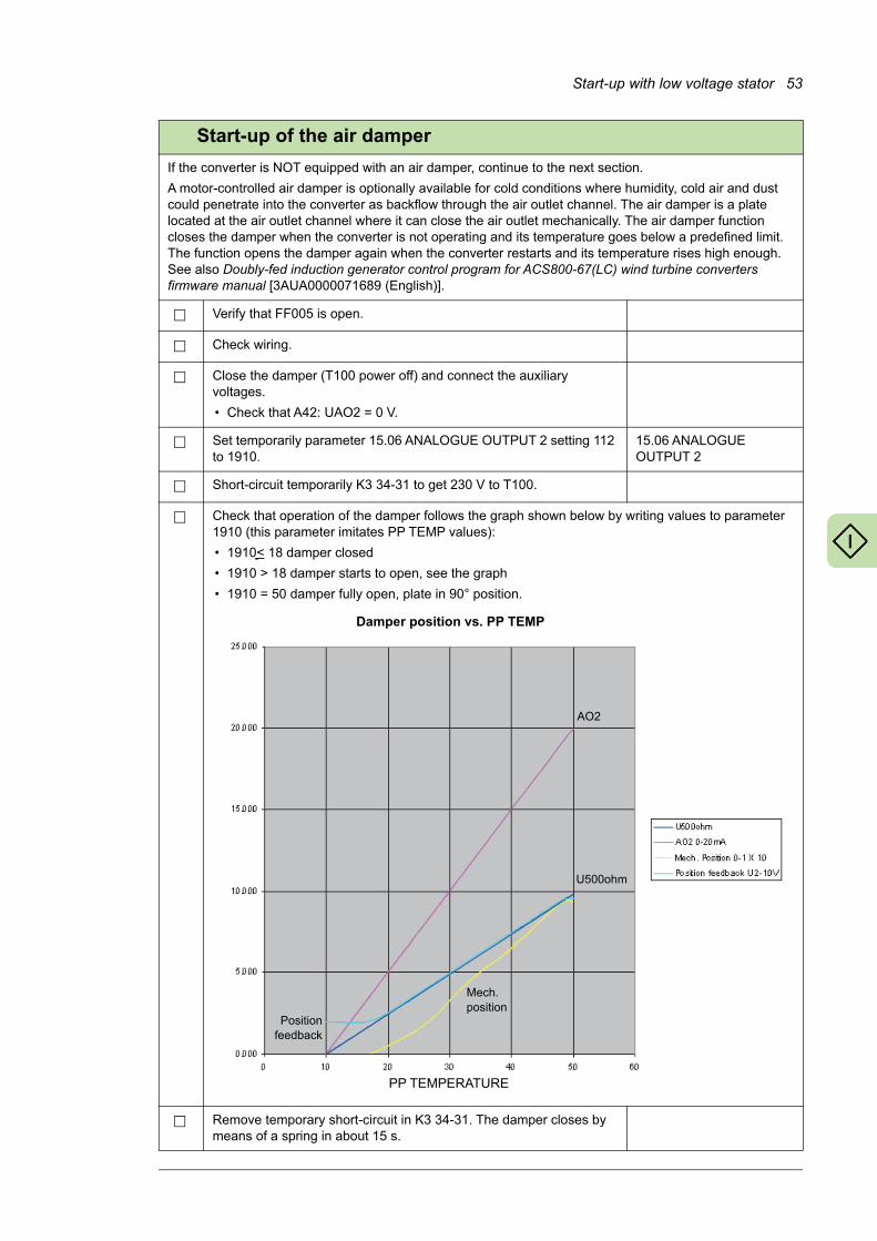
Start-up with low voltage stator 53
Start-up of the air damper
If the converter is NOT equipped with an air damper, continue to the next section.
A motor-controlled air damper is optionally available for cold conditions where humidity, cold air and dust could penetrate into the converter as backflow through the air outlet channel. The air damper is a plate located at the air outlet channel where it can close the air outlet mechanically. The air damper function closes the damper when the converter is not operating and its temperature goes below a predefined limit. The function opens the damper again when the converter restarts and its temperature rises high enough. See also Doubly-fed induction generator control program for ACS800-67(LC) wind turbine converters firmware manual [3AUA0000071689 (English)].
Verify that FF005 is open.
Check wiring.
Close the damper (T100 power off) and connect the auxiliary voltages.
• Check that A42: UAO2 = 0 V.
Set temporarily parameter 15.06 ANALOGUE OUTPUT 2 setting 112 to 1910.
15.06 ANALOGUE OUTPUT 2
Short-circuit temporarily K3 34-31 to get 230 V to T100.
Check that operation of the damper follows the graph shown below by writing values to parameter 1910 (this parameter imitates PP TEMP values):
• 1910< 18 damper closed
• 1910 > 18 damper starts to open, see the graph
• 1910 = 50 damper fully open, plate in 90° position.
Remove temporary short-circuit in K3 34-31. The damper closes by means of a spring in about 15 s.
Damper position vs. PP TEMP
PP TEMPERATURE
AO2
U500ohm
Positionfeedback
Mech. position

54 Start-up with low voltage stator
Set parameter 15.06 ANALOGUE OUTPUT 2 to 112. 15.06 ANALOGUE OUTPUT 2
Check that all temporary installations are removed.
Close the door of the sliding frame.
Close FF005.
Switch the converter to Local control mode.
Start the converter at zero speed.
Check that the air damper starts to open when the converter PP TEMP starts to increase. You can monitor signals by means of DriveWindow:
• 01.12 PP TEMPERATURE
• 15.06 ANALOGUE OUTPUT 2 (damper control)
• 05.07 ISU AI1 [V] (damper position is monitored via this signal).
Final settings
Disable the parameter lock by setting parameter 16.03 PASS CODE to 358 or 564 in rotor-side and grid-side converter.
Note: Not needed with grid-side converter control program IWXR74xx.
16.03 PASS CODE
Set the stator current fault trip limit to 0 A. 30.04 STATOR CURR TRIP
Make special parameter settings (if any) according to eg, grid code. See section Setting the parameters according to grid code on page 108.
Lock the parameter settings by setting parameter 16.01 PARAM LOCK to ON in rotor-side converter.
Note: Not needed with grid-side converter control program IWXR74xx.
16.01 PARAM LOCK
Create a Backup Package [as MyBackupPackage.BPG] for rotor-side and grid-side converter and save it.
Save parameters in text file [as MyParameterValues.txt] in rotor-side and grid-side converter.
Remember to have pass code open in order to store parameter values above group 100 also.
Switch the rotor-side converter back to Remote control mode.
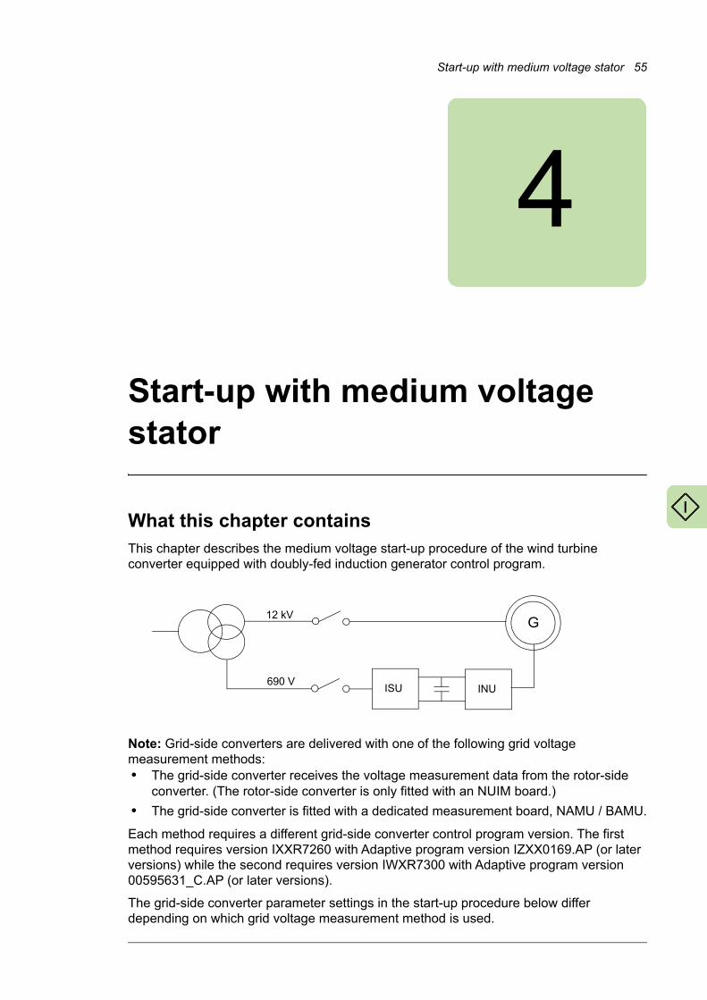
Start-up with medium voltage stator 55
4
Start-up with medium voltage stator
What this chapter containsThis chapter describes the medium voltage start-up procedure of the wind turbine converter equipped with doubly-fed induction generator control program.
Note: Grid-side converters are delivered with one of the following grid voltage measurement methods:• The grid-side converter receives the voltage measurement data from the rotor-side
converter. (The rotor-side converter is only fitted with an NUIM board.)
• The grid-side converter is fitted with a dedicated measurement board, NAMU / BAMU.
Each method requires a different grid-side converter control program version. The first method requires version IXXR7260 with Adaptive program version IZXX0169.AP (or later versions) while the second requires version IWXR7300 with Adaptive program version 00595631_C.AP (or later versions).
The grid-side converter parameter settings in the start-up procedure below differ depending on which grid voltage measurement method is used.
690 VISU INU
G12 kV

56 Start-up with medium voltage stator
How to start-up the converterIn the start-up procedure presented here, the converter is operated locally from DriveWindow PC tool. For instruction on how to operate DriveWindow, see DriveWindow Online Help or DriveWindow 2 user’s manual [3AFE64560981 (English)].
The start-up mainly uses rotor-side converter parameters. When grid-side converter parameters are needed, a reference to the grid-side converter parameter list in ACS800-67(LC) doubly-fed induction generator control program firmware manual [3AUA0000071689 (English)] is given.
After the first start-up, the converter can be powered up without using these start-up functions. The start-up procedure can be repeated later if start-up data needs to be changed.
WARNING! The generator may not be connected to the grid when the rotor is not rotating. The rotor speed must be in the operational speed area (normally 70…130% of the generator nominal speed). Otherwise grid connection is not
allowed by the converter control program.
Note: For testing purposes the rotor-side converter can be started without closing the stator breaker at zero speed. Note that the control program is not able to execute the commissioning check routines at zero speed. The grid-side converter can be tested even though the generator is not rotating.
Before you start, ensure you have the generator data sheet on hand.
Safety
The start-up may only be carried out by a qualified electrician.
The safety instructions must be followed during the start-up procedure. See ACS800-67 wind turbine converters for asynchronous slip ring generators hardware manual [3AFE68392454
(English)].
Check the installation. See the installation checklist in the converter hardware manual.
Power-up
Connect fibre optic cables temporarily between channel CH3 of the rotor-side converter NDCU unit and the DDCS Communication (RUSB-02) card or PCMCIA card.
If an active crowbar is in use (optional), the crowbar test requires communication with the NDCU unit of the rotor-side converter and RDCU unit of the grid-side converter: Connect the fibre optic cables in a ring connection between channel CH3 of the NDCU unit and channel CH3 of the RMIO board and the DDCS Communication (RUSB-02) card or PCMCIA card.
When a PCMCIA card is used, follow the instructions included in the DriveWindow kit.
Apply main power.
Start the DriveWindow program.
Switch the rotor-side converter to local control mode.
Manual start-up data entering
Upload the parameter and signal lists.
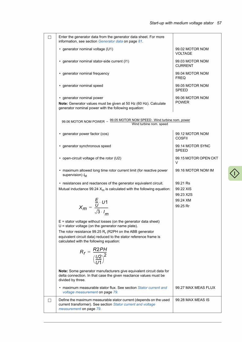
Start-up with medium voltage stator 57
Enter the generator data from the generator data sheet. For more information, see section Generator data on page 81.
• generator nominal voltage (U1) 99.02 MOTOR NOM VOLTAGE
• generator nominal stator-side current (I1) 99.03 MOTOR NOM CURRENT
• generator nominal frequency 99.04 MOTOR NOM FREQ
• generator nominal speed 99.05 MOTOR NOM SPEED
• generator nominal power
Note: Generator values must be given at 50 Hz (60 Hz). Calculate generator nominal power with the following equation:
99.06 MOTOR NOM POWER
• generator power factor (cos) 99.12 MOTOR NOM COSFII
• generator synchronous speed 99.14 MOTOR SYNC SPEED
• open-circuit voltage of the rotor (U2) 99.15 MOTOR OPEN CKT V
• maximum allowed long time rotor current limit (for reactive power supervision) IM
99.16 MOTOR NOM IM
• resistances and reactances of the generator equivalent circuit.
Mutual inductance 99.24 Xm is calculated with the following equation:
E = stator voltage without losses (on the generator data sheet)U = stator voltage (on the generator name plate).
The rotor resistance 99.25 Rr (R2PH on the ABB generator
equivalent circuit data) reduced to the stator reference frame is calculated with the following equation:
Note: Some generator manufacturers give equivalent circuit data for delta connection. In that case the given reactance values must be divided by three.
99.21 Rs
99.22 XIS
99.23 X2S
99.24 XM
99.25 Rr
• maximum measurable stator flux. See section Stator current and voltage measurement on page 79.
99.27 MAX MEAS FLUX
Define the maximum measurable stator current (depends on the used current transformer). See section Stator current and voltage measurement on page 79.
99.28 MAX MEAS IS
99.06 MOTOR NOM POWER 99.05 MOTOR NOM SPEED Wind turbine nom. power⋅Wind turbine nom. speed
----------------------------------------------------------------------------------------------------------------------------------------------------=
Xm
EU---- U1⋅
3 Im⋅------------------=
RrR2PH
U2U1-------- 2------------------=

58 Start-up with medium voltage stator
Enter the number of encoder pulses. 50.04 PULSE NR
Select the communication profile used by the converter. For more information see section ABB Drives communication profile on page 90.
16.11 COMM PROFILE
Set parameter limits in group 20 LIMITS according to the process requirements.
20.05 USER POS TORQ LIM defines the motoring torque limit 20.06 USER NEG TORQ LIM defines the generating torque limit.
20.05 USER POS TORQ LIM
20.06 USER NEG TORQ LIM
20.21 SWITCH ON SPEED
20.22 SWITCH OFF SPEED
Select the reactive power reference type (PERCENT/KVAR/PHII/COSPHII).
23.04 REACT POW REF SEL
Set the stator overcurrent trip limit.
During commissioning when the converter runs in local control mode without torque references, set parameter value to approximately15 A. After commissioning set parameter value to 0 A.
30.04 STATOR CURR TRIP
Set the over/underspeed limits. 30.09 OVERSPEED LIMIT
30.10 UNDERSPEED LIMIT
Activate the external communication by setting parameter 98.02 COMM MODULE to FBA DSET 10.
98.02 COMM MODULE
Set the fieldbus adapter data according to the used external control system.
Note: The configuration parameters are not visible if the module is not connected or activated in the control program. See appropriate adapter Hardware Manual.
51 MASTER ADAPTER
Activate the fieldbus adapter supervision toggle bit (if needed). 70.25 TOGGLE BIT SEL
70.26 TOGGLE ADDRESS SEL
Define the current limit and breaking device type for the grid connection between stator and grid.
0 A = Medium voltage circuit breaker used for disconnecting stator from grid.
20.27 CONT OPEN CUR
Check that the breaker/contactor configuration of the converter is set correctly according to the delivery. For configurations available and corresponding parameter settings, see section Stator circuit connection to grid on page 36.
16.20 GRID CONNECT MODE
Time setting
Set rotor-side converter 16.01 PARAM LOCK to OFF.
Set the date and time as follows:
• Set parameter 95.07 RTC MODE value to SET.
• Check/adjust the date and time by parameters 95.01…95.06.
• Set parameter 95.07 RTC MODE value to SHOW.
16.01 PARAM LOCK
95.07 RTC MODE
95.01…95.06
Digital inputs
Check that all digital inputs are connected properly. 01.15 DI STATUS

Start-up with medium voltage stator 59
Grid-side converter and crowbar test
Communication between the grid-side converter and the rotor-side converter is checked by controlling the grid-side converter unit via the rotor-side converter unit parameters.
Set parameter 21.01 ISU LOCAL CTR WORD to 9 (hex), ie, 1001 (bin): grid-side converter starts charging the DC capacitors, closes the main contactor and starts modulating.
21.01 ISU LOCAL CTR WORD
Check the grid-side converter status. Note: Only the three least significant bits are relevant in this case.
231H (1000110001 bin) before the grid-side converter is started
737H (11100110111 bin) when the grid-side converter is running
238H (1000111000 bin) when the grid-side converter has tripped on a fault.
05.10 ISU STATUS WORD
Check that the DC link is charged. 01.10 DC VOLTAGE
Check that the Voltage and Current Measurement Unit NUIM-6x functions, ie, the grid frequency is positive and the grid voltage is correct.
01.05 NET FREQUENCY
01.11 MAINS VOLTAGE
Stop the grid-side converter by setting parameter 21.01 ISU LOCAL CTR WORD to 0 (hex).
21.01 ISU LOCAL CTR WORD
Check the functioning of the crowbar by starting and stopping the grid-side converter. (Parameter 21.01 ISU LOCAL CTR WORD setting 9 (hex) = START and 0 (hex) = STOP)
When DC voltage is 0 V, 01.15 DI STATUS bit 5 value must be 0 (ie, crowbar inactive). 01.15 DI STATUS = 1303 (hex) When DC voltage exceeds 100 V, 01.15 DI STATUS bit 4 value must be 1 (ie, crowbar active). 01.15 DI STATUS = 1713 (hex)
01.15 DI STATUS
Enable the grid-side converter parameter lock by setting parameter 16.03 PASS CODE to 2303. Parameter groups 100…202 become visible when the parameter lock is enabled.
16.03 PASS CODE
Set grid-side converter 16.01 PARAM LOCK to OFF. 16.01 PARAM LOCK
If the converter is NOT equipped with an active crowbar, continue to the next section.
Activate the active crowbar by setting rotor-side converter parameter 31.01 CROWBAR HW TYPE according to the type of active crowbar in use.
Note: If the converter is equipped with an active crowbar, it must always be activated by parameter 31.01 even when low voltage ride through (LVRT) and / or grid support is not used.
31.01 CROWBAR HW TYPE
Start the grid-side converter by setting parameter 21.01 ISU LOCAL CTR WORD to 9 (hex).
21.01 ISU LOCAL CTR WORD
Check the communication between the rotor-side converter and the active crowbar:The communication is OK if the temperature of the crowbar is about 25…40 °C and the converter does not trip for crowbar communication time-out.
06.13 CB IGBT TEMP
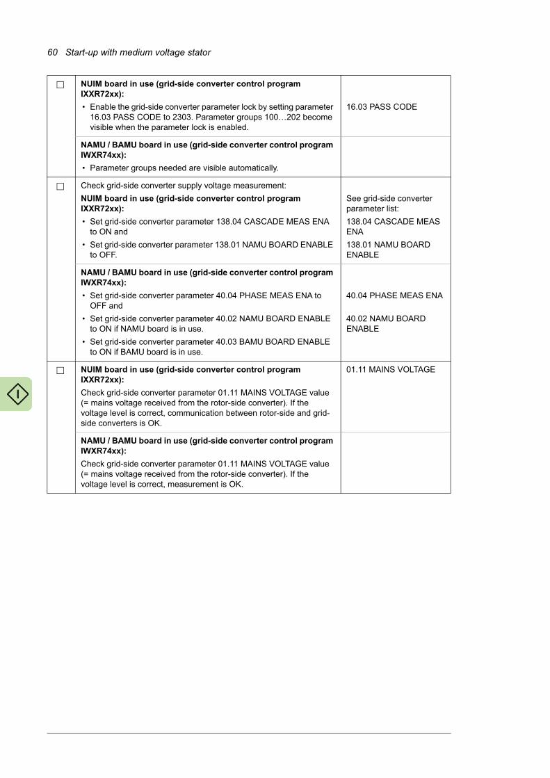
60 Start-up with medium voltage stator
NUIM board in use (grid-side converter control program IXXR72xx):
• Enable the grid-side converter parameter lock by setting parameter 16.03 PASS CODE to 2303. Parameter groups 100…202 become visible when the parameter lock is enabled.
16.03 PASS CODE
NAMU / BAMU board in use (grid-side converter control program IWXR74xx):
• Parameter groups needed are visible automatically.
Check grid-side converter supply voltage measurement:
NUIM board in use (grid-side converter control program IXXR72xx):
• Set grid-side converter parameter 138.04 CASCADE MEAS ENA to ON and
• Set grid-side converter parameter 138.01 NAMU BOARD ENABLE to OFF.
See grid-side converter parameter list:
138.04 CASCADE MEAS ENA
138.01 NAMU BOARD ENABLE
NAMU / BAMU board in use (grid-side converter control program IWXR74xx):
• Set grid-side converter parameter 40.04 PHASE MEAS ENA to OFF and
• Set grid-side converter parameter 40.02 NAMU BOARD ENABLE to ON if NAMU board is in use.
• Set grid-side converter parameter 40.03 BAMU BOARD ENABLE to ON if BAMU board is in use.
40.04 PHASE MEAS ENA
40.02 NAMU BOARD ENABLE
NUIM board in use (grid-side converter control program IXXR72xx):
Check grid-side converter parameter 01.11 MAINS VOLTAGE value (= mains voltage received from the rotor-side converter). If the voltage level is correct, communication between rotor-side and grid-side converters is OK.
01.11 MAINS VOLTAGE
NAMU / BAMU board in use (grid-side converter control program IWXR74xx):
Check grid-side converter parameter 01.11 MAINS VOLTAGE value (= mains voltage received from the rotor-side converter). If the voltage level is correct, measurement is OK.
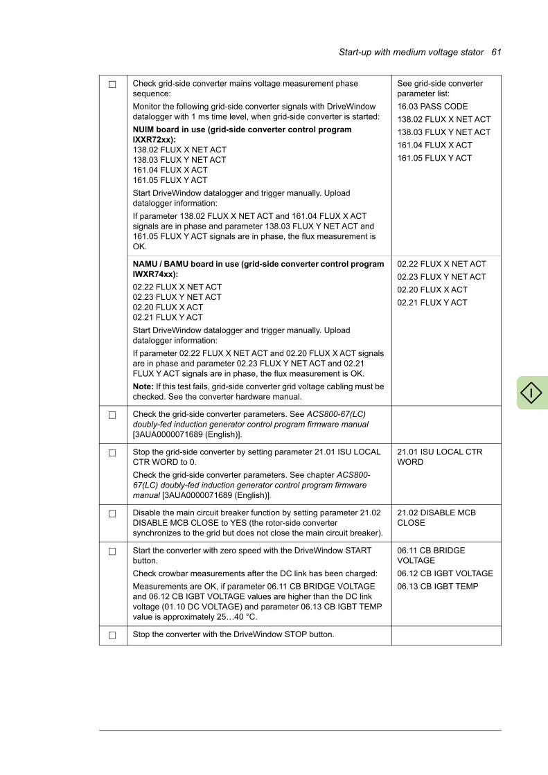
Start-up with medium voltage stator 61
Check grid-side converter mains voltage measurement phase sequence:
Monitor the following grid-side converter signals with DriveWindow datalogger with 1 ms time level, when grid-side converter is started:
NUIM board in use (grid-side converter control program IXXR72xx):138.02 FLUX X NET ACT138.03 FLUX Y NET ACT161.04 FLUX X ACT161.05 FLUX Y ACT
Start DriveWindow datalogger and trigger manually. Upload datalogger information:
If parameter 138.02 FLUX X NET ACT and 161.04 FLUX X ACT signals are in phase and parameter 138.03 FLUX Y NET ACT and 161.05 FLUX Y ACT signals are in phase, the flux measurement is OK.
See grid-side converter parameter list:
16.03 PASS CODE
138.02 FLUX X NET ACT
138.03 FLUX Y NET ACT
161.04 FLUX X ACT
161.05 FLUX Y ACT
NAMU / BAMU board in use (grid-side converter control program IWXR74xx):
02.22 FLUX X NET ACT02.23 FLUX Y NET ACT02.20 FLUX X ACT02.21 FLUX Y ACT
Start DriveWindow datalogger and trigger manually. Upload datalogger information:
If parameter 02.22 FLUX X NET ACT and 02.20 FLUX X ACT signals are in phase and parameter 02.23 FLUX Y NET ACT and 02.21 FLUX Y ACT signals are in phase, the flux measurement is OK.
Note: If this test fails, grid-side converter grid voltage cabling must be checked. See the converter hardware manual.
02.22 FLUX X NET ACT
02.23 FLUX Y NET ACT
02.20 FLUX X ACT
02.21 FLUX Y ACT
Check the grid-side converter parameters. See ACS800-67(LC) doubly-fed induction generator control program firmware manual [3AUA0000071689 (English)].
Stop the grid-side converter by setting parameter 21.01 ISU LOCAL CTR WORD to 0.
Check the grid-side converter parameters. See chapter ACS800-67(LC) doubly-fed induction generator control program firmware manual [3AUA0000071689 (English)].
21.01 ISU LOCAL CTR WORD
Disable the main circuit breaker function by setting parameter 21.02 DISABLE MCB CLOSE to YES (the rotor-side converter synchronizes to the grid but does not close the main circuit breaker).
21.02 DISABLE MCB CLOSE
Start the converter with zero speed with the DriveWindow START button.
Check crowbar measurements after the DC link has been charged:
Measurements are OK, if parameter 06.11 CB BRIDGE VOLTAGE and 06.12 CB IGBT VOLTAGE values are higher than the DC link voltage (01.10 DC VOLTAGE) and parameter 06.13 CB IGBT TEMP value is approximately 25…40 °C.
06.11 CB BRIDGE VOLTAGE
06.12 CB IGBT VOLTAGE
06.13 CB IGBT TEMP
Stop the converter with the DriveWindow STOP button.
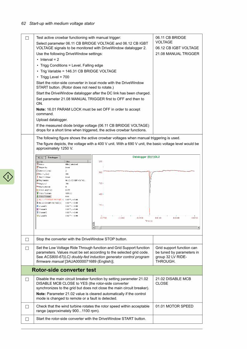
62 Start-up with medium voltage stator
Test active crowbar functioning with manual trigger:
Select parameter 06.11 CB BRIDGE VOLTAGE and 06.12 CB IGBT VOLTAGE signals to be monitored with DriveWindow datalogger 2.
Use the following DriveWindow settings:
• Interval = 2
• Trigg Conditions = Level, Falling edge
• Trig Variable = 146.31 CB BRIDGE VOLTAGE
• Trigg Level = 700
Start the rotor-side converter in local mode with the DriveWindow START button. (Rotor does not need to rotate.)
Start the DriveWindow datalogger after the DC link has been charged.
Set parameter 21.08 MANUAL TRIGGER first to OFF and then to ON.
Note: 16.01 PARAM LOCK must be set OFF in order to accept command.
Upload datalogger.
If the measured diode bridge voltage (06.11 CB BRIDGE VOLTAGE) drops for a short time when triggered, the active crowbar functions.
06.11 CB BRIDGE VOLTAGE
06.12 CB IGBT VOLTAGE
21.08 MANUAL TRIGGER
The following figure shows the active crowbar voltages when manual triggering is used.
The figure depicts, the voltage with a 400 V unit. With a 690 V unit, the basic voltage level would be approximately 1250 V.
Stop the converter with the DriveWindow STOP button.
Set the Low Voltage Ride Through function and Grid Support function parameters. Values must be set according to the selected grid code. See ACS800-67(LC) doubly-fed induction generator control program firmware manual [3AUA0000071689 (English)].
Grid support function can be tuned by parameters in group 32 LV RIDE-THROUGH.
Rotor-side converter test
Disable the main circuit breaker function by setting parameter 21.02 DISABLE MCB CLOSE to YES (the rotor-side converter synchronizes to the grid but does not close the main circuit breaker).
Note: Parameter 21.02 value is cleared automatically if the control mode is changed to remote or a fault is detected.
21.02 DISABLE MCB CLOSE
Check that the wind turbine rotates the rotor speed within acceptable range (approximately 900...1100 rpm).
01.01 MOTOR SPEED
Start the rotor-side converter with the DriveWindow START button.
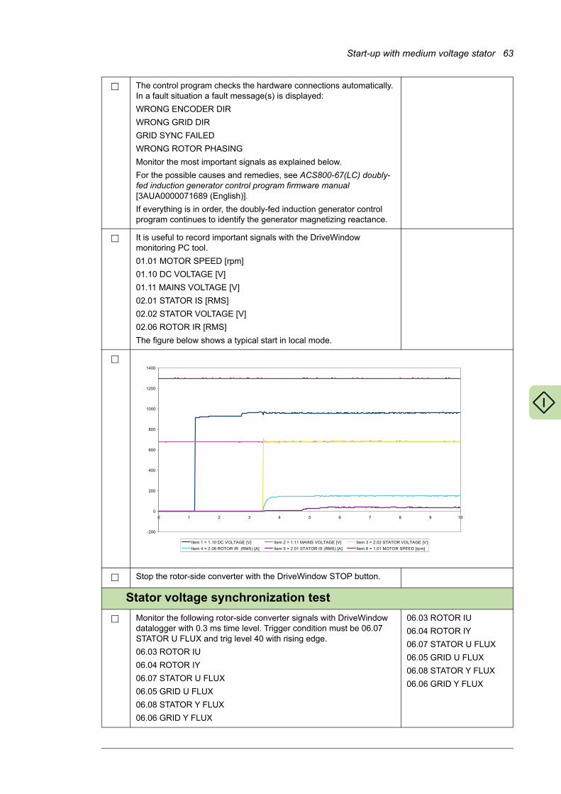
Start-up with medium voltage stator 63
The control program checks the hardware connections automatically. In a fault situation a fault message(s) is displayed:
WRONG ENCODER DIR
WRONG GRID DIR
GRID SYNC FAILED
WRONG ROTOR PHASING
Monitor the most important signals as explained below.
For the possible causes and remedies, see ACS800-67(LC) doubly-fed induction generator control program firmware manual [3AUA0000071689 (English)].
If everything is in order, the doubly-fed induction generator control program continues to identify the generator magnetizing reactance.
It is useful to record important signals with the DriveWindow monitoring PC tool.
01.01 MOTOR SPEED [rpm]
01.10 DC VOLTAGE [V]
01.11 MAINS VOLTAGE [V]
02.01 STATOR IS [RMS]
02.02 STATOR VOLTAGE [V]
02.06 ROTOR IR [RMS]
The figure below shows a typical start in local mode.
Stop the rotor-side converter with the DriveWindow STOP button.
Stator voltage synchronization test
Monitor the following rotor-side converter signals with DriveWindow datalogger with 0.3 ms time level. Trigger condition must be 06.07 STATOR U FLUX and trig level 40 with rising edge.
06.03 ROTOR IU
06.04 ROTOR IY
06.07 STATOR U FLUX
06.05 GRID U FLUX
06.08 STATOR Y FLUX
06.06 GRID Y FLUX
06.03 ROTOR IU
06.04 ROTOR IY
06.07 STATOR U FLUX
06.05 GRID U FLUX
06.08 STATOR Y FLUX
06.06 GRID Y FLUX
����
�
���
���
���
��
����
����
����
� � � � � � � N , ��
�+�*���������� �O�����1�POQ �+�*����������-��?��O�����1�POQ �+�*�����������������O�����1�POQ
�+�*��������������������A�-�C�P�Q �+�*��������������������A�-�C�P�Q �+�*����������-������E11 �P)(*Q
�
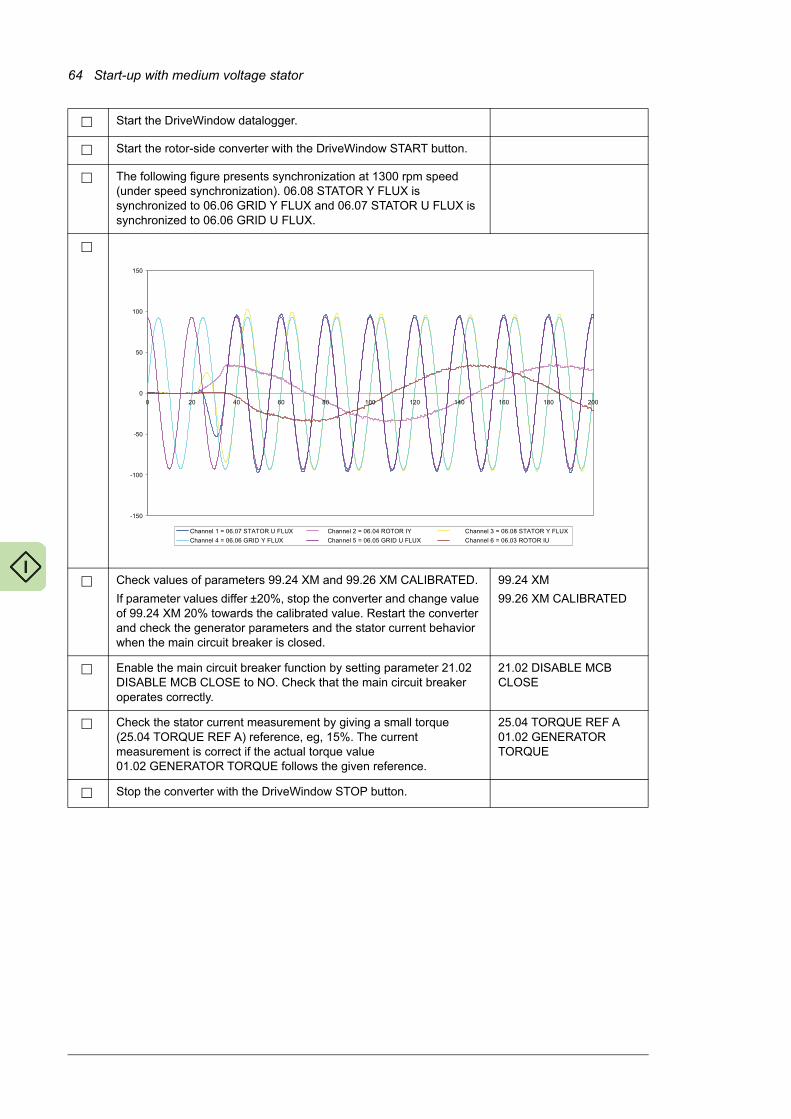
64 Start-up with medium voltage stator
Start the DriveWindow datalogger.
Start the rotor-side converter with the DriveWindow START button.
The following figure presents synchronization at 1300 rpm speed (under speed synchronization). 06.08 STATOR Y FLUX is synchronized to 06.06 GRID Y FLUX and 06.07 STATOR U FLUX is synchronized to 06.06 GRID U FLUX.
Check values of parameters 99.24 XM and 99.26 XM CALIBRATED.
If parameter values differ ±20%, stop the converter and change value of 99.24 XM 20% towards the calibrated value. Restart the converter and check the generator parameters and the stator current behavior when the main circuit breaker is closed.
99.24 XM
99.26 XM CALIBRATED
Enable the main circuit breaker function by setting parameter 21.02 DISABLE MCB CLOSE to NO. Check that the main circuit breaker operates correctly.
21.02 DISABLE MCB CLOSE
Check the stator current measurement by giving a small torque (25.04 TORQUE REF A) reference, eg, 15%. The current measurement is correct if the actual torque value 01.02 GENERATOR TORQUE follows the given reference.
25.04 TORQUE REF A01.02 GENERATOR TORQUE
Stop the converter with the DriveWindow STOP button.
����
����
���
�
��
���
���
� �� �� �� � ��� ��� ��� ��� �� ���
�� �������06�07������������������ �� �������06��4������������������ �� �������06�08������������������
�� �������06�0����� ����������� �� �������06�0����� ����������� �� �������06��3������������������
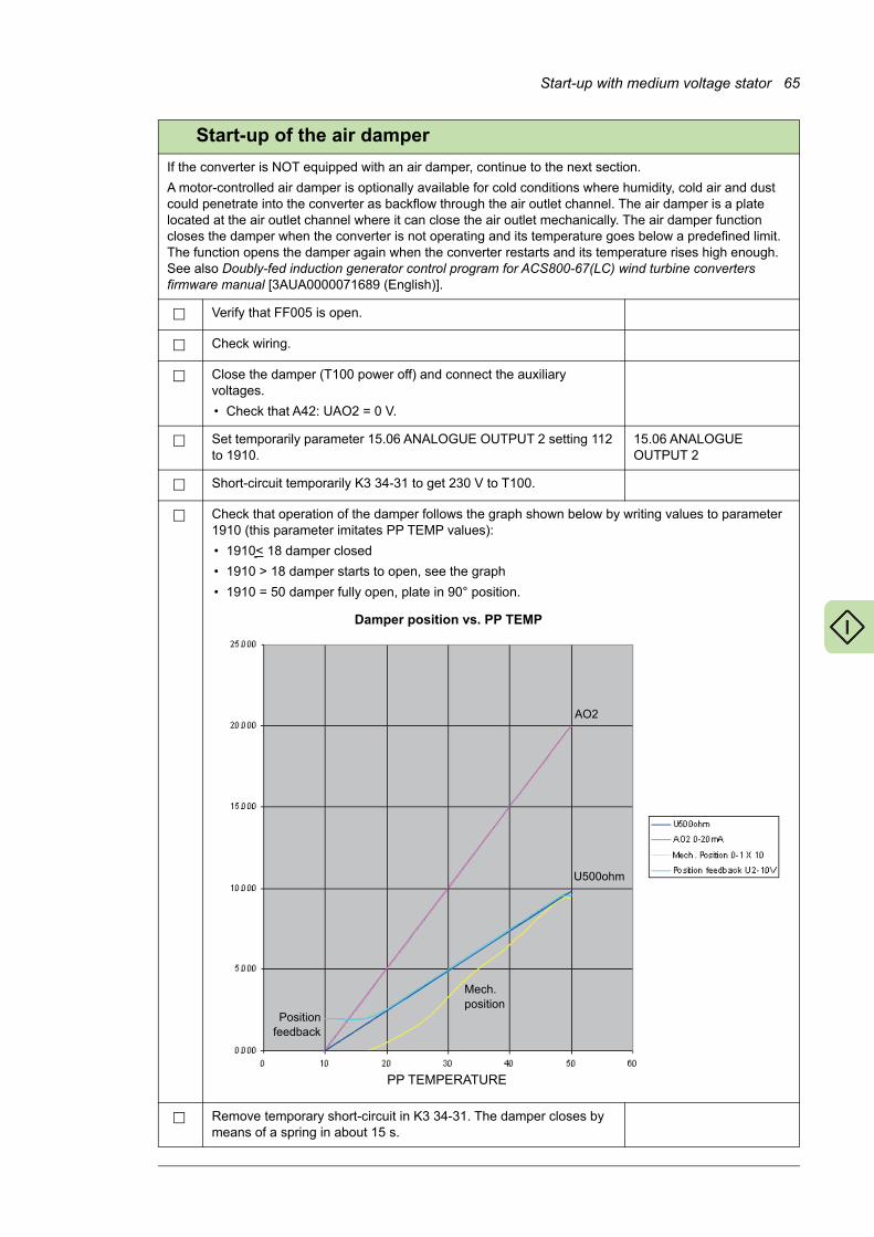
Start-up with medium voltage stator 65
Start-up of the air damper
If the converter is NOT equipped with an air damper, continue to the next section.
A motor-controlled air damper is optionally available for cold conditions where humidity, cold air and dust could penetrate into the converter as backflow through the air outlet channel. The air damper is a plate located at the air outlet channel where it can close the air outlet mechanically. The air damper function closes the damper when the converter is not operating and its temperature goes below a predefined limit. The function opens the damper again when the converter restarts and its temperature rises high enough. See also Doubly-fed induction generator control program for ACS800-67(LC) wind turbine converters firmware manual [3AUA0000071689 (English)].
Verify that FF005 is open.
Check wiring.
Close the damper (T100 power off) and connect the auxiliary voltages.
• Check that A42: UAO2 = 0 V.
Set temporarily parameter 15.06 ANALOGUE OUTPUT 2 setting 112 to 1910.
15.06 ANALOGUE OUTPUT 2
Short-circuit temporarily K3 34-31 to get 230 V to T100.
Check that operation of the damper follows the graph shown below by writing values to parameter 1910 (this parameter imitates PP TEMP values):
• 1910< 18 damper closed
• 1910 > 18 damper starts to open, see the graph
• 1910 = 50 damper fully open, plate in 90° position.
Remove temporary short-circuit in K3 34-31. The damper closes by means of a spring in about 15 s.
Damper position vs. PP TEMP
PP TEMPERATURE
AO2
U500ohm
Positionfeedback
Mech. position
66 Start-up with medium voltage stator
Set parameter 15.06 ANALOGUE OUTPUT 2 to 112. 15.06 ANALOGUE OUTPUT 2
Check that all temporary installations are removed.
Close the door of the sliding frame.
Close FF005.
Switch the converter to Local control mode.
Start the converter at zero speed.
Check that the air damper starts to open when the converter PP TEMP starts to increase. You can monitor signals by means of DriveWindow:
• 01.12 PP TEMPERATURE
• 15.06 ANALOGUE OUTPUT 2 (damper control)
• 05.07 ISU AI1 [V] (damper position is monitored via this signal).
Final settings
Disable the parameter lock by setting parameter 16.03 PASS CODE to 358 or 564 in rotor-side and grid-side converter.
Note: Not needed with grid-side converter control program IWXR74xx.
16.03 PASS CODE
Set the stator current fault trip limit to 0 A. 30.04 STATOR CURR TRIP
Make special parameter settings (if any) according to eg, grid code. See section Setting the parameters according to grid code on page 108.
Lock the parameter settings by setting parameter 16.01 PARAM LOCK to ON in rotor-side converter.
Note: Not needed with grid-side converter control program IWXR74xx.
16.01 PARAM LOCK
Create a Backup Package [as MyBackupPackage.BPG] for rotor-side and grid-side converter and save it.
Save parameters in text file [as MyParameterValues.txt] in rotor-side and grid-side converter.
Remember to have pass code open in order to store parameter values above group 100 also.
Switch the rotor-side converter back to Remote control mode.
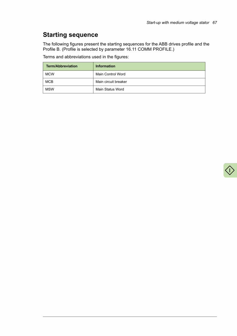
Start-up with medium voltage stator 67
Starting sequenceThe following figures present the starting sequences for the ABB drives profile and the Profile B. (Profile is selected by parameter 16.11 COMM PROFILE.)
Terms and abbreviations used in the figures:
Term/Abbreviation Information
MCW Main Control Word
MCB Main circuit breaker
MSW Main Status Word

68 Start-up with medium voltage stator
0
1
2
4
3 RUN
5
6
7 RESET
8
9
MC
W 7
.01
0 RDYON
1 RDYRUN (ready)
2 RDYREF (operational)
4
3 TRIPPED
5
6
7 ALARM
8
9
MS
W 8
.10
11 MCB3 STATUS
12
13
15
14 TOGGLE BIT
DC voltage (ISU-INU)
Start command X2: 1-2
Heating ON
Auxiliary power ON
Fieldbus comm. starts
ISU contactor
ISU modulation
INU modulation
Grid connected
Grid connection
Cabinet temperature and humidity OK
Booting time
Discharged
Synchr. to grid
Stop sequence
Time
2
7
8
9
10
11
12
13
14
15
3
4
5
6
1
ABB Drives profile

Start-up with medium voltage stator 69
Profile B
0 1)
1
2
4
3 RUN
5
6
7 RESET
8
9
MC
W 7
.01
0 RDYON
1 RDYRUN (ready)
2 RDYREF (operational)
4
3 TRIPPED
5
6
7
8
9
MS
t W 8
.10
11 MCB3 STATUS
12
13
15
14 TOGGLE
DC voltage (ISU-INU)
Start command X2: 1-2
Heating ON
Auxiliary power ON
Fieldbus comm. starts
ISU contactor
ISU modulation
INU modulation
Grid connected
Grid connection
Cabinet temperature and humidity OK
Booting time
Discharged
Syncr. to grid
Stop sequence
Time
2
7
8
9
10
11
12
13
14
15
3
4
5
6
1
17
16
Actual speed
20.21 SWITCH ON SPEED
1) Bit 0 is not used in this profile.
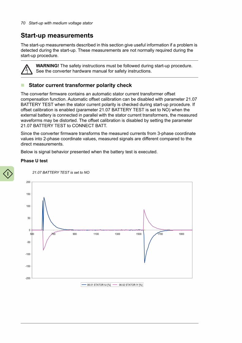
70 Start-up with medium voltage stator
Start-up measurementsThe start-up measurements described in this section give useful information if a problem is detected during the start-up. These measurements are not normally required during the start-up procedure.
WARNING! The safety instructions must be followed during start-up procedure. See the converter hardware manual for safety instructions.
Stator current transformer polarity check
The converter firmware contains an automatic stator current transformer offset compensation function. Automatic offset calibration can be disabled with parameter 21.07 BATTERY TEST when the stator current polarity is checked during start-up procedure. If offset calibration is enabled (parameter 21.07 BATTERY TEST is set to NO) when the external battery is connected in parallel with the stator current transformers, the measured waveforms may be distorted. The offset calibration is disabled by setting the parameter 21.07 BATTERY TEST to CONNECT BATT.
Since the converter firmware transforms the measured currents from 3-phase coordinate values into 2-phase coordinate values, measured signals are different compared to the direct measurements.
Below is signal behavior presented when the battery test is executed.
Phase U test
��
��,
��
�,
,
�
�,
�
, � - �� �( �, �� �-
06�������/1�23�457 06�������/1�28�457
21.07 BATTERY TEST is set to NO

Start-up with medium voltage stator 71
Phase U current transformer polarity check:• +1.5 V is connected to X1:1 of the NUIM-6x unit and
• -1.5 V is connected to X1:2 of the NUIM-6x unit.
06.01 STATOR IU measures positive values. The values depend on the used scaling factors.
06.02 STATOR IY measures negative values, which are approximately 60% of the STATOR IU.
Note: Values depend on the battery voltage and current transformer transformation ratio.
Note: When battery is removed, the signals behave in the opposite way.
�D
�(
��
��
�
�
(
D
,
�
� � ( D , � � � - �
� ����/1�23�45
����/1�28�457
21.07 BATTERY TEST is set to CONNECT BATT

72 Start-up with medium voltage stator
Phase W test
Phase W current transformer check:• +1.5 V is connected to X2:1 of the NUIM-6x unit and
• -1.5 V is connected to X2:2 of the NUIM-6x unit.
����
����
����
���
�
��
���
���
���� ���� ���� ���� ��� ���� ���� ����
�� �����06���������������� �� �����06����������������
21.07 BATTERY TEST is set to NO
-100
-80
-60
-40
-20
0
20
40
60
80
100
0 1 2 3 4 5 6 7 8 9 10
06.01 STATOR IU [%]
06.02 STATOR IY [%]
21.07 BATTERY TEST is set to CONNECT BATT

Start-up with medium voltage stator 73
06.01 STATOR IU is zero.
06.02 STATOR IY measures negative values. Absolute values are higher than with the phase U test.
Note: Values depend on the battery voltage and current transformer transformation ratio.
Note: When battery is removed, the signals behaves in the opposite way.
Test at zero speed
For testing purposes it is possible to start the converter at zero speed. Then the rotor-side converter modulates but the main circuit breaker will not be closed. The produced slip ring current is approximately 20…30 A which does not harm the slip rings during a short test period.
This feature can be used in the commissioning when the wind is so weak that it rotates the blades but can not accelerate the rotor to the minimum speed ie, 1 m/s needed at start-up.
The figure below represents normal behavior when the rotor-side converter is started for a short time.
0
200
400
600
800
1000
1200
0 2000 4000 6000 8000 10000
0
20
40
60
80
100
1201.10 DC VOLTAGE [v]
1.11 MAINS VOLTAGE [V]
2.01 STATOR IS (rms) [A]
2.06 ROTOR IR (rms) [A] 2.02 STATOR VOLTAGE [v]
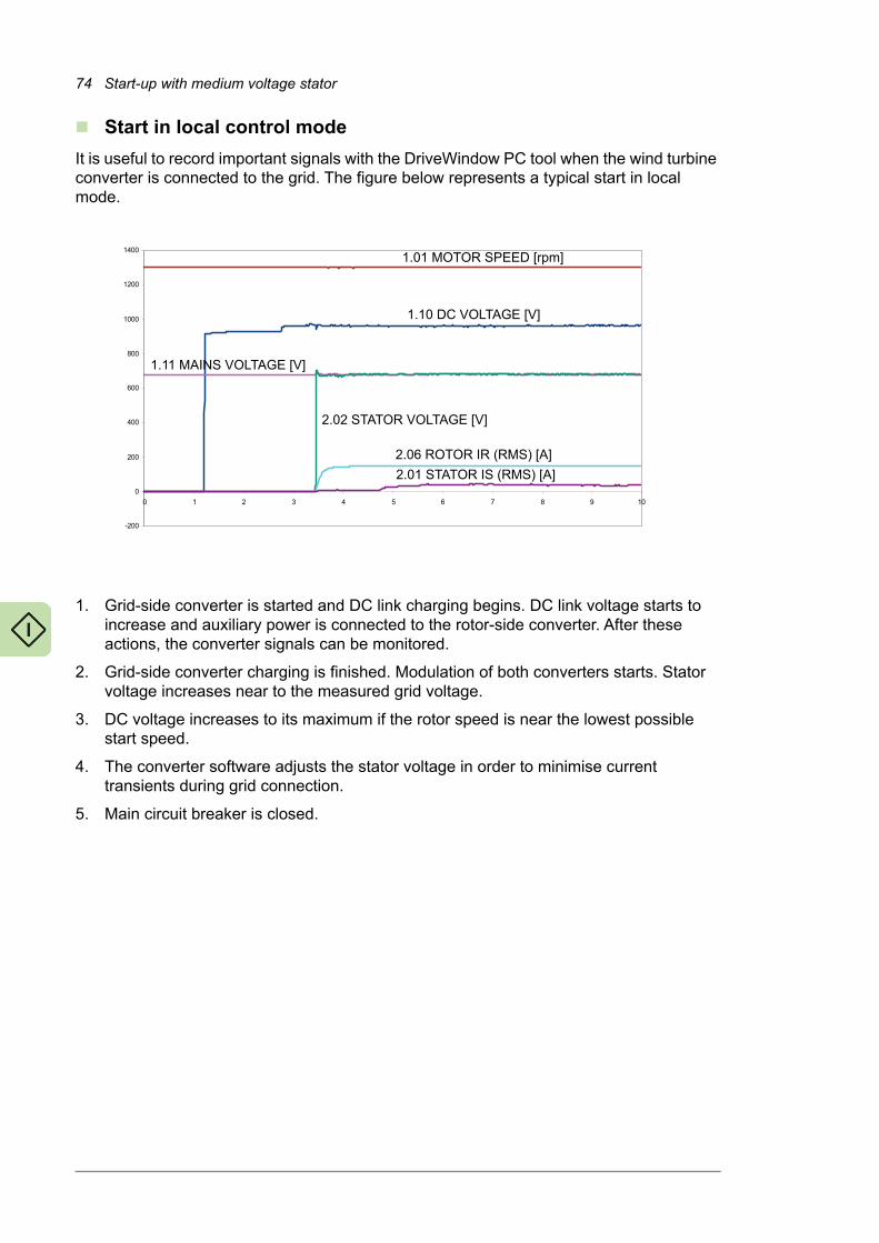
74 Start-up with medium voltage stator
Start in local control mode
It is useful to record important signals with the DriveWindow PC tool when the wind turbine converter is connected to the grid. The figure below represents a typical start in local mode.
1. Grid-side converter is started and DC link charging begins. DC link voltage starts to increase and auxiliary power is connected to the rotor-side converter. After these actions, the converter signals can be monitored.
2. Grid-side converter charging is finished. Modulation of both converters starts. Stator voltage increases near to the measured grid voltage.
3. DC voltage increases to its maximum if the rotor speed is near the lowest possible start speed.
4. The converter software adjusts the stator voltage in order to minimise current transients during grid connection.
5. Main circuit breaker is closed.
-200
0
200
400
600
800
1000
1200
1400
0 1 2 3 4 5 6 7 8 9 10
1.01 MOTOR SPEED [rpm]
1.10 DC VOLTAGE [V]
1.11 MAINS VOLTAGE [V]
2.02 STATOR VOLTAGE [V]
2.06 ROTOR IR (RMS) [A]
2.01 STATOR IS (RMS) [A]
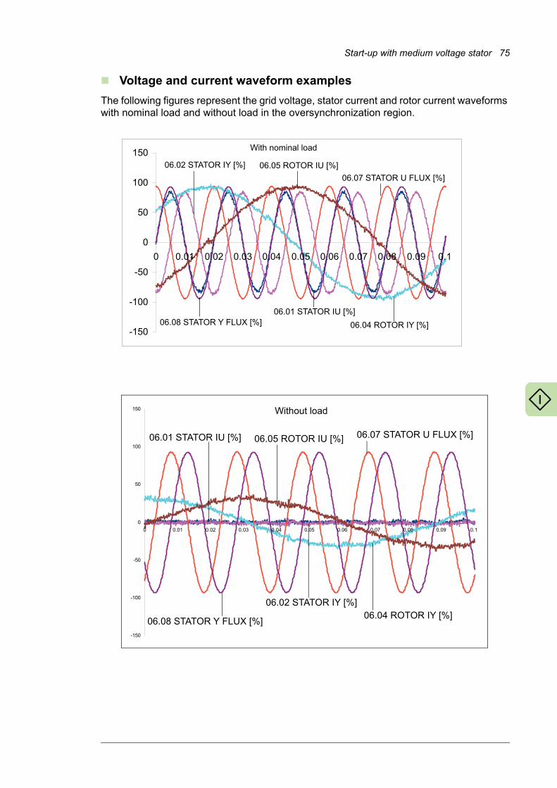
Start-up with medium voltage stator 75
Voltage and current waveform examples
The following figures represent the grid voltage, stator current and rotor current waveforms with nominal load and without load in the oversynchronization region.
-150
-100
-50
0
50
100
150
0 0.01 0.02 0.03 0.04 0.05 0.06 0.07 0.08 0.09 0.1
06.08 STATOR Y FLUX [%]
06.02 STATOR IY [%]
With nominal load
06.05 ROTOR IU [%]
06.07 STATOR U FLUX [%]
06.01 STATOR IU [%]
06.04 ROTOR IY [%]
-150
-100
-50
0
50
100
150
0 0.01 0.02 0.03 0.04 0.05 0.06 0.07 0.08 0.09 0.1
06.01 STATOR IU [%]
06.04 ROTOR IY [%]
06.05 ROTOR IU [%]
06.08 STATOR Y FLUX [%]
06.02 STATOR IY [%]
06.07 STATOR U FLUX [%]
Without load

76 Start-up with medium voltage stator
Practical examples 77
5
Practical examples
What this chapter containsThis chapter contains examples on how to determine values for critical parameter settings.
Setting up the fieldbus
Fieldbus interfaces
For descriptions of the fieldbus connections, refer to• ACS800 IGBT supply control program firmware manual [3AFE68315735 (English)]
• ACS800 grid-side control program firmware manual [3AUA0000075077 (English)]
• ACS800-67(LC) doubly-fed induction generator control program firmware manual [3AUA0000071689 (English)]
• fieldbus adapter manuals.

78 Practical examples
Entering start-up data and torque settings
Calculating/setting the motor nominal torque
You need• the DFIG data sheets from the generator supplier for the DFIG of the wind turbine that
contain
• rated (nominal) values
• DFIG equivalent circuit (from stator side, in star connection)
• calculated operation points and type test data (optional)
• calculation tool, like Excel or calculator.
If the equivalent circuit is given in rotor-side, convert the values to stator-side.
If the equivalent circuit is in delta connection or given for main voltage, divide the reactance and resistance values by three.
Parameters 99.05 MOTOR NOM SPEED and 99.06 MOTOR NOM POWER contain motor nominal speed (rpm) and power. Motor nominal torque (100%) is calculated from the values of parameters in group 99 START-UP DATA. There is no parameter for it and there is no other way of setting the nominal torque.
Torque set-point
Torque is limited by parameters 20.05 USER POS TORQ LIM and 20.06 USER NEG TORQ LIM. The parameters should be set to values which are achievable with the generator-drive current capacity combination defined in the design.
If the torque reference given by the turbine controller is too high (ie, the pull-out torque of the generator or current capacity of the converter have been reached), the converter will limit the torque.
In extreme cases, if the torque reference is remarkably higher than what is allowed by the generator-drive current capacity combination, and the limitation of current by limiting torque does not succeed, the converter will trip on overcurrent. It stops operation immediately and the torque on the generator shaft disappears. Necessary overspeed and safety system dynamics margins must be maintained in the system design.
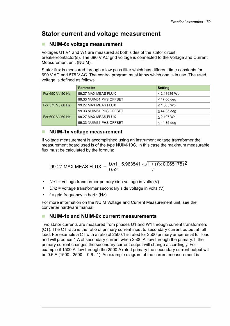
Practical examples 79
Stator current and voltage measurement
NUIM-6x voltage measurement
Voltages U1,V1 and W1 are measured at both sides of the stator circuit breaker/contactor(s). The 690 V AC grid voltage is connected to the Voltage and Current Measurement unit (NUIM).
Stator flux is measured through a low pass filter which has different time constants for 690 V AC and 575 V AC. The control program must know which one is in use. The used voltage is defined as follows:
NUIM-1x voltage measurement
If voltage measurement is accomplished using an instrument voltage transformer the measurement board used is of the type NUIM-10C. In this case the maximum measurable flux must be calculated by the formula:
• Un1 = voltage transformer primary side voltage in volts (V)
• Un2 = voltage transformer secondary side voltage in volts (V)
• f = grid frequency in hertz (Hz)
For more information on the NUIM Voltage and Current Measurement unit, see the converter hardware manual.
NUIM-1x and NUIM-6x current measurements
Two stator currents are measured from phases U1 and W1 through current transformers (CT). The CT ratio is the ratio of primary current input to secondary current output at full load. For example a CT with a ratio of 2500:1 is rated for 2500 primary amperes at full load and will produce 1 A of secondary current when 2500 A flow through the primary. If the primary current changes the secondary current output will change accordingly. For example if 1500 A flow through the 2500 A rated primary the secondary current output will be 0.6 A (1500 : 2500 = 0.6 : 1). An example diagram of the current measurement is
Parameter Setting
For 690 V / 50 Hz 99.27 MAX MEAS FLUX < 2.43936 Wb
99.33 NUIM61 PHS OFFSET < 47.06 deg
For 575 V / 60 Hz 99.27 MAX MEAS FLUX < 1.605 Wb
99.33 NUIM61 PHS OFFSET < 44.35 deg
For 690 V / 60 Hz 99.27 MAX MEAS FLUX < 2.407 Wb
99.33 NUIM61 PHS OFFSET < 44.35 deg
99.27 MAX MEAS FLUXUn1Un2----------- 5.963541 1 f 0.065175×( )+⋅
f---------------------------------------------------------------------------------
2⋅=

80 Practical examples
shown below. In this example the parameter 16.20 GRID CONNECT MODE is set to MCB1+MCB3/B.
The maximum measurable stator current must be set by a parameter. The value is calculated with the following equation:
CT = current transformer ratio
The polarity of a current transformer is determined by the direction the coils are wound around the core (clockwise or counterclockwise) and the way the leads are brought out of the transformer case. Current transformers have subtractive polarity and following designations for installation: P1: primary current, line-facing direction; P2: primary current, load-facing direction; and S1: secondary current. Correct polarity has to be taken into account when installing and connecting current transformer to power metering.
Sometimes it is not possible to install current transformers mechanically so that current flow is from P1 to P2 which is standard. This means that measurement polarity is reversed. In this case the polarity can be corrected by entering a negative value in this parameter.
MCB2 DFIGINUISU
NUIM
X1:1
X1:2
X2:1
X2:2
L1 L2 L3
MCB3MCB1
NDCU
P1,K P2,L
S1,k S2,l
P1,K P2,L
S1,k S2,l
L1
L2
L3
L1
L2
L3 W1
V1
U1
W1
V1 U
1
K
L
M
U2
V2
W2
U2
V2
W2
LCL
Optional
99.28 MAX MEAS IS 4,5 V2,73333 ohm----------------------------------- CT⋅=

Practical examples 81
Generator data
Generator rating plate equivalent circuit parameters
The equivalent circuit of the generator is shown below. Note that the equivalent circuit is to be are derived looking from the stator-side ie, the voltages and currents are reflected on the stator-side. To calculate the equivalent rotor circuit parameters (resistance and inductance) from the rotor-side to stator-side, appropriate stator-to-rotor conversion ratio information should be used.
Since the application measures both rotor- and stator-side quantities, the identification run method is not used with doubly-fed induction generator control. The control needs to be given the following data (from the generator data sheet) manually.
Generator data Parameter
Rated stator voltage 99.02 MOTOR NOM VOLTAGE
Rated stator current 99.03 MOTOR NOM CURRENT
Rated stator frequency 99.04 MOTOR NOM FREQ
Rated generator nominal speed (rotor short-circuited)
99.05 MOTOR NOM SPEED
Note: As generator, positive slip.
Rated generator power 99.06 MOTOR NOM POWERNote: See the calculations below.
P.F (rotor short-circuited) 99.12 MOTOR NOM COSFII
Generator synchronous speed 99.14 MOTOR SYNC SPEED
Rss
Iss
Urs
(Xss = sLs
s)��
rs
Lss Lr
s Irs
Rrs
Lmsm
s
ss
Uss
-j r rs��
(Xrs = sLr
s)��
j s ss��
99.21 Rs
99.02 MOTOR NOM VOLTAGE
99.22 X1S
99.03 MOTOR NOM CURRENT
99.16 MOTORNOM IM 99.24 XM
99.23 X2S 99.25 Rr
99.15 MOTOROPEN CKT V
Note: Open-circuited voltage when the rotor is mechanically locked and nominal stator voltage
is connected to the stator circuit.

82 Practical examples
Note: Some generator manufacturers give equivalent circuit data for delta connection. In that case the given reactance values must be divided by three.
Transformation ratio between the stator and the rotor. Defined when rotor shaft is mechanically locked and nominal stator voltage is fed to the stator windings.
99.15 MOTOR OPEN CKT V
Note: Rotor open-circuit voltage.
Long time rotor current limitation 99.16 MOTOR NOM IMNote: IM is not needed in the slip ring generator model. IM is used for defining the maximum allowed long time rotor current limit.
Stator resistance (Rs) 99.21 Rs
Stator leakage reactance 99.22 X1S
Rotor leakage reactance 99.23 X2S
Mutual reactance 99.24 XMNote: See the equation on page 86.
Rotor resistance (Rr) 99.25 RrNote: Rr must be referred to the stator frame. See the equation on page 86.
Generator data Parameter

Practical examples 83
Parameters of parameter group 99
Parameter Description Source Description
99.02 MOTOR NOM VOLTAGE
Defines the nominal generator voltage.
Rated stator voltage in data sheet
99.03 MOTOR NOM CURRENT
Defines the nominal generator stator-side current.
Rated stator current in data sheet
The value is for information only. It is not used by the firmware in any way.
99.04 MOTOR NOM FREQ
Defines the nominal generator frequency.
Rated stator (grid) frequency in data sheet
The value is either 50 Hz or 60 Hz depending on the grid.
99.05 MOTOR NOM SPEED
Defines the nominal generator speed.
Defined in data sheet or calculated estimate.
See separate instruction below.
Used for the modeling of the DFIG.
The speed of DFIG when operating rotor short-circuited with nominal power.
99.06 MOTOR NOM POWER
Defines the nominal generator power.
Calculated value
See separate instruction below.
Used for the scaling of the torque reference.
Note: This is not the rated power of the DFIG.
99.12 MOTOR NOM COS FII
Defines the generator power factor at nominal loading point.
Must be equal to the value on the generator data sheet.
Power factor in data sheet The value is for information only. It is not used by the firmware in any way.
99.14 MOTOR SYNC SPEED
Defines the synchronous speed of the generator.
Select based on motor pole pair and grid frequency.
Select
99.15 MOTOR OPEN CKT V
Defines the open-circuit voltage of the rotor. That is, rotor voltage without load when nominal voltage is connected to the stator and the rotor is locked (U2 on the generator data sheet).
Locked rotor voltage in data sheet.
Transformation ratio between the stator and the rotor. Defined when rotor shaft is mechanically locked and nominal stator voltage is fed to the stator windings.
99.16 MOTOR NOM IM
Defines the maximum limit of the rotor current to avoid generator overheating.
If the rotor current exceeds the value of parameter 99.16, the capacitive reactive power is ramped down until the current has decreased below the value of the parameter 99.16.
The limit for rotor current protection.
Select from the data sheet
• largest rotor current in the calculated operation points, or
• maximum rotor current
The maximum limit of the rotor current defined by the generator supplier.
99.21 Rs Defines the stator resistance.
Stator resistance (Rs) of
equivalent circuit
DFIG characteristics value
99.22 X1S Defines the stator leakage reactance.
Stator leakage reactance of equivalent circuit
DFIG characteristics value
99.23 X2S Defines the rotor leakage reactance reduced to the stator side.
Rotor leakage reactance of equivalent circuit
DFIG characteristics value
50 Hz 60 Hz4-p 1500 18006-p 1000 1200
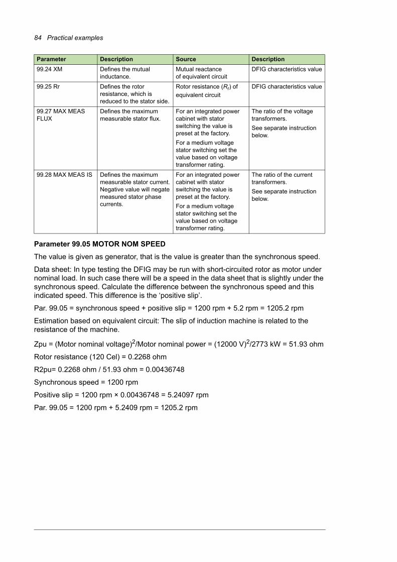
84 Practical examples
Parameter 99.05 MOTOR NOM SPEED
The value is given as generator, that is the value is greater than the synchronous speed.
Data sheet: In type testing the DFIG may be run with short-circuited rotor as motor under nominal load. In such case there will be a speed in the data sheet that is slightly under the synchronous speed. Calculate the difference between the synchronous speed and this indicated speed. This difference is the ‘positive slip’.
Par. 99.05 = synchronous speed + positive slip = 1200 rpm + 5.2 rpm = 1205.2 rpm
Estimation based on equivalent circuit: The slip of induction machine is related to the resistance of the machine.
Zpu = (Motor nominal voltage)2/Motor nominal power = (12000 V)2/2773 kW = 51.93 ohm
Rotor resistance (120 Cel) = 0.2268 ohm
R2pu= 0.2268 ohm / 51.93 ohm = 0.00436748
Synchronous speed = 1200 rpm
Positive slip = 1200 rpm × 0.00436748 = 5.24097 rpm
Par. 99.05 = 1200 rpm + 5.2409 rpm = 1205.2 rpm
99.24 XM Defines the mutual inductance.
Mutual reactance of equivalent circuit
DFIG characteristics value
99.25 Rr Defines the rotor resistance, which is reduced to the stator side.
Rotor resistance (Rr) of
equivalent circuit
DFIG characteristics value
99.27 MAX MEAS FLUX
Defines the maximum measurable stator flux.
For an integrated power cabinet with stator switching the value is preset at the factory.
For a medium voltage stator switching set the value based on voltage transformer rating.
The ratio of the voltage transformers.
See separate instruction below.
99.28 MAX MEAS IS Defines the maximum measurable stator current. Negative value will negate measured stator phase currents.
For an integrated power cabinet with stator switching the value is preset at the factory.
For a medium voltage stator switching set the value based on voltage transformer rating.
The ratio of the current transformers.
See separate instruction below.
Parameter Description Source Description
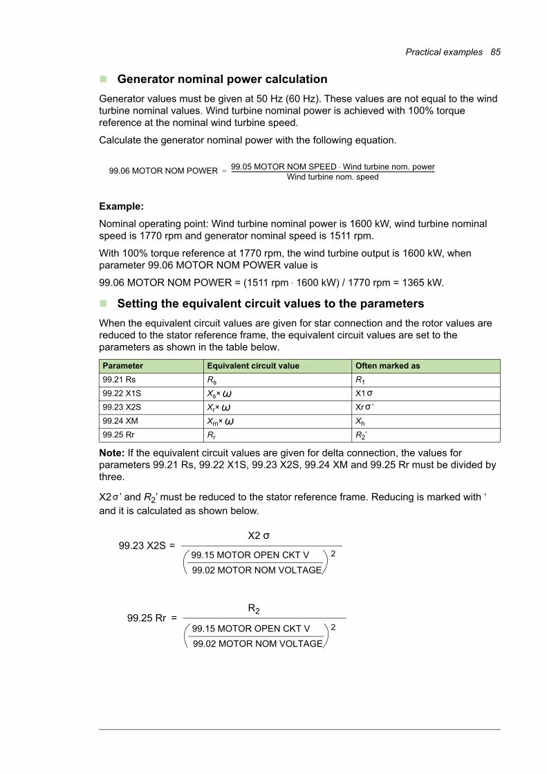
Practical examples 85
Generator nominal power calculation
Generator values must be given at 50 Hz (60 Hz). These values are not equal to the wind turbine nominal values. Wind turbine nominal power is achieved with 100% torque reference at the nominal wind turbine speed.
Calculate the generator nominal power with the following equation.
Example:
Nominal operating point: Wind turbine nominal power is 1600 kW, wind turbine nominal speed is 1770 rpm and generator nominal speed is 1511 rpm.
With 100% torque reference at 1770 rpm, the wind turbine output is 1600 kW, when parameter 99.06 MOTOR NOM POWER value is
99.06 MOTOR NOM POWER = (1511 rpm · 1600 kW) / 1770 rpm = 1365 kW.
Setting the equivalent circuit values to the parameters
When the equivalent circuit values are given for star connection and the rotor values are reduced to the stator reference frame, the equivalent circuit values are set to the parameters as shown in the table below.
Note: If the equivalent circuit values are given for delta connection, the values for parameters 99.21 Rs, 99.22 X1S, 99.23 X2S, 99.24 XM and 99.25 Rr must be divided by three.
X2 ’ and R2’ must be reduced to the stator reference frame. Reducing is marked with ‘ and it is calculated as shown below.
Parameter Equivalent circuit value Often marked as
99.21 Rs Rs R1
99.22 X1S Xs× X1
99.23 X2S Xr× Xr ’
99.24 XM Xm× Xh
99.25 Rr Rr R2’
99.06 MOTOR NOM POWER 99.05 MOTOR NOM SPEED Wind turbine nom. power⋅Wind turbine nom. speed
----------------------------------------------------------------------------------------------------------------------------------------------------=
��
��
��
= 99.23 X2SX2
2
= 99.25 RrR2
99.15 MOTOR OPEN CKT V
99.02 MOTOR NOM VOLTAGE
299.15 MOTOR OPEN CKT V
99.02 MOTOR NOM VOLTAGE
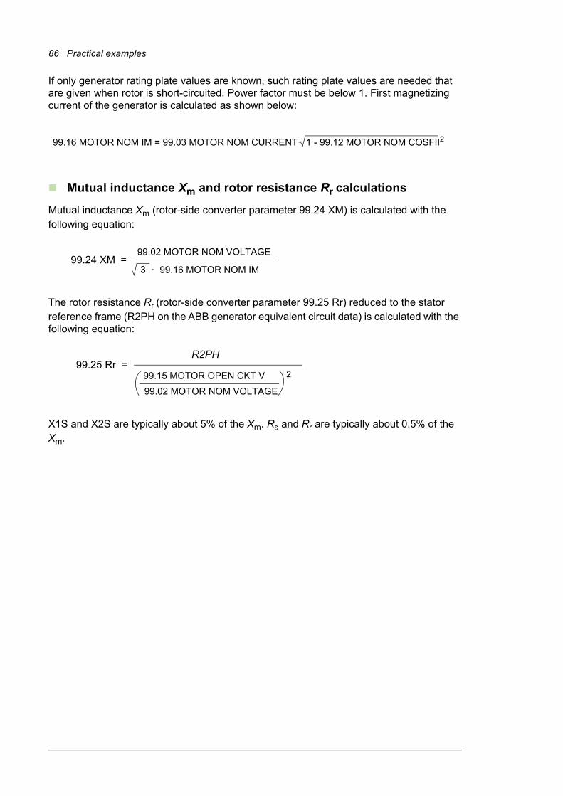
86 Practical examples
If only generator rating plate values are known, such rating plate values are needed that are given when rotor is short-circuited. Power factor must be below 1. First magnetizing current of the generator is calculated as shown below:
Mutual inductance Xm and rotor resistance Rr calculations
Mutual inductance Xm (rotor-side converter parameter 99.24 XM) is calculated with the following equation:
The rotor resistance Rr (rotor-side converter parameter 99.25 Rr) reduced to the stator reference frame (R2PH on the ABB generator equivalent circuit data) is calculated with the following equation:
X1S and X2S are typically about 5% of the Xm. Rs and Rr are typically about 0.5% of the Xm.
99.16 MOTOR NOM IM = 99.03 MOTOR NOM CURRENT· 1 - 99.12 MOTOR NOM COSFII2
= 99.24 XM99.02 MOTOR NOM VOLTAGE
· 99.16 MOTOR NOM IM3
= 99.25 RrR2PH
299.15 MOTOR OPEN CKT V
99.02 MOTOR NOM VOLTAGE
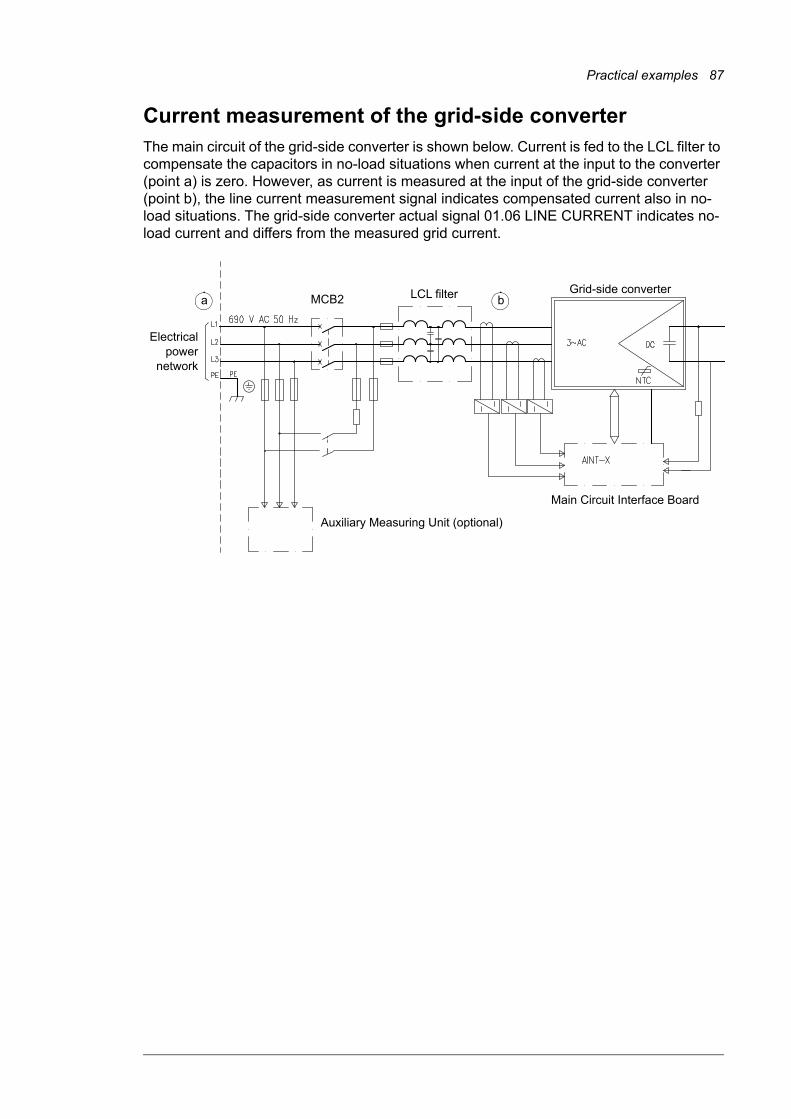
Practical examples 87
Current measurement of the grid-side converterThe main circuit of the grid-side converter is shown below. Current is fed to the LCL filter to compensate the capacitors in no-load situations when current at the input to the converter (point a) is zero. However, as current is measured at the input of the grid-side converter (point b), the line current measurement signal indicates compensated current also in no-load situations. The grid-side converter actual signal 01.06 LINE CURRENT indicates no-load current and differs from the measured grid current.
Grid-side converterLCL filter
Auxiliary Measuring Unit (optional)
Main Circuit Interface Board
a bMCB2
Electricalpower
network
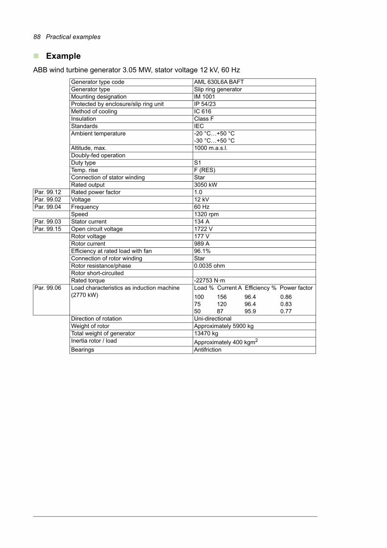
88 Practical examples
Example
ABB wind turbine generator 3.05 MW, stator voltage 12 kV, 60 Hz
Generator type code AML 630L6A BAFTGenerator type Slip ring generatorMounting designation IM 1001Protected by enclosure/slip ring unit IP 54/23Method of cooling IC 616Insulation Class FStandards IECAmbient temperature -20 °C…+50 °C
-30 °C…+50 °CAltitude, max. 1000 m.a.s.l.Doubly-fed operationDuty type S1Temp. rise F (RES)Connection of stator winding StarRated output 3050 kW
Par. 99.12 Rated power factor 1.0Par. 99.02 Voltage 12 kVPar. 99.04 Frequency 60 Hz
Speed 1320 rpmPar. 99.03 Stator current 134 APar. 99.15 Open circuit voltage 1722 V
Rotor voltage 177 VRotor current 989 AEfficiency at rated load with fan 96.1%Connection of rotor winding StarRotor resistance/phase 0.0035 ohmRotor short-circuitedRated torque -22753 N·m
Par. 99.06 Load characteristics as induction machine (2770 kW)
Load % Current A Efficiency % Power factor
100 156 96.4 0.8675 120 96.4 0.8350 87 95.9 0.77
Direction of rotation Uni-directionalWeight of rotor Approximately 5900 kgTotal weight of generator 13470 kgInertia rotor / load Approximately 400 kgm2
Bearings Antifriction

Practical examples 89
AML 630L6A BAFT
Equivalent circuit corresponding to star connection
Permanent loading points:
* Par. 99.16
However, if higher current is needed to use for a short period (defined by the supplier of the generator), a higher limit can be used. The PLC must supervise the temperatures of the generator and avoid overheating it.
RunningPar. 99.21 Stator resistance R1 (120 °C) 0.42756 ohm
Par. 99.22 Stator reactance X1 4.4324 ohm
Par. 99.24 Magnetizing reactance Xm 177.59 ohm
StartingStator resistance R1 (60 °C) 0.39143 ohm
Stator reactance X1 4.3061 ohm
Ambient conditionStator resistance R1 (50 °C) 0.34346 ohm
RunningPar. 99.25 Rotor resistance R2
’(120 °C) 0.22680 ohm
Par. 99.23 Rotor reactance X2’ 5.8101 ohm
Iron loss resistance RFe 5.13 ohm
Starting
Rotor resistance R2’ (60 °C) 0.22678 ohm
Rotor reactance X2’ 5.6445 ohm
Ambient condition
Rotor resistance R2’ (50 °C) 0.19899 ohm
U [V] F [Hz] N [rpm] P [kW] p.f. S [kVA] Ir [A] Ur [V] Max. time Max. amb.12000 60 1320 3150 0.95cap. 3300 1168* 192 Continuous 50 °C12000 60 1320 3300 1 3300 1063 179 Continuous 50 °C
X1 X2’ R2
’ / s
XmUN / 3 RFe
R1

90 Practical examples
Transient loading points (load cycle transient time / 60 min) refer to specification PDC0198 (revision G, chapter 7.3, page 12).
ABB Drives communication profileThe following sections show control sequence examples using the ABB Drives communication profile. The Main Control Word (MCW) is the principal means of controlling the converter from WTC. The Control Word is sent to the converter by the WTC. The converter switches between its states according to the bit-coded instructions of the Control Word. The Main Status Word (MSW) contains status information, sent to the WTC by the converter.
Starting sequence
See section Starting sequence on page 67.
U [V] F [Hz] N [rpm] P [kW] p.f. Ir [A] Ur [V] Tran. time Max. amb.11760 60 1260 3380 1 1157 83 10 min 50 °C12000 60 1260 3380 1 1138 85 10 min 50 °C12240 60 1260 3380 1 1119 86 10 min 50 °C11760 60 1320 3545 1 1158 174 10 min 50 °C12000 60 1320 3545 1 1139 178 10 min 50 °C12240 60 1320 3545 1 1120 181 10 min 50 °C11760 60 1380 3875 1 1207 266 10 min 50 °C12000 60 1380 3875 1 1187 271 10 min 50 °C12240 60 1380 3875 1 1167 277 10 min 50 °C
Start up data Setting Unit Generator data 99.02 MOTOR NOM VOLTAGE 12000 V Voltage 99.03 MOTOR NOM CURRENT 134 A Stator current 99.04 MOTOR NOM FREQ 60 Hz Frequency 99.05 MOTOR NOM SPEED 1205.2 rpm Calculated (see above) 99.06 MOTOR NOM POWER 2773 kW Calculated (see above) 99.12 MOTOR NOM COSFII 1 - Rated power factor 99.14 MOTOR SYNC SPEED 1200 rpm Selected for 6 poles at 60 Hz 99.15 MOTOR OPEN CKT V 1722 V Open circuit voltage 99.16 MOTOR NOM IM 1168 A In this example, the value in the table for
permanent loading points (see above) is used. 99.21 Rs 427.56 mohm Stator resistance R1 (120 °C)
99.22 X1S 4432.4 mohm Stator reactance X1
99.23 X2S 5810.1 mohm Rotor reactance X2
99.24 XM 177590 mohm Magnetizing reactance Xm
99.25 Rr 226.8 mohm Rotor resistance R2 (120 °C)
99.26 XM CALIBRATED N/A mohm Estimated by the firmware – do not set. 99.27 MAX MEAS FLUX 44.35224 Wb Calculated 99.28 MAX MEAS IS -329.2687 A Calculated
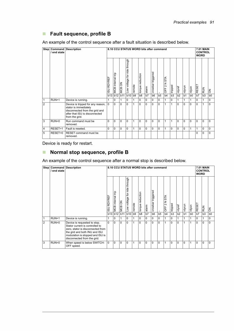
Practical examples 91
Fault sequence, profile B
An example of the control sequence after a fault situation is described below.
Device is ready for restart.
Normal stop sequence, profile B
An example of the control sequence after a normal stop is described below.
Step Command / end state
Description 8.10 CCU STATUS WORD bits after command 7.01 MAIN CONTROL WORD
ISU
RD
YR
EF
MC
B in
tern
al t
rip
MC
B O
N
Low
vo
ltag
e fo
r ri
de
thro
ug
h
rem
ote
torq
ue r
ed
uct
ion
ala
rm
cro
wb
ar t
rigg
ere
d
- OF
F 2
N S
TA
trip
ped
rdyr
ef
rdyr
un
rdyo
n
RE
SE
T
RU
N
ON
b13 b12 b11 b10 b9 b8 b7 b6 b5 b4 b3 b2 b1 b0 b7 b3 b0
1 RUN=1 Device is running. 1 0 1 0 1 0 0 0 0 1 0 1 1 1 0 1 0
2 Device is tripped for any reason, stator is immediately disconnected from the grid and after that ISU is disconnected from the grid.
0 0 0 0 1 0 0 0 0 1 1 0 0 0 0 1 0
3 RUN=0 Run command must be removed.
0 0 0 0 1 0 0 0 0 1 1 0 0 0 0 0 0
4 RESET=1 Fault is reseted. 0 0 0 0 1 0 0 0 0 1 0 0 0 1 1 0 0
5 RESET=0 RESET command must be removed.
0 0 0
Step Command / end state
Description 8.10 CCU STATUS WORD bits after command 7.01 MAIN CONTROL WORD
ISU
RD
YR
EF
MC
B in
tern
al t
rip
MC
B O
N
Lo
w v
olta
ge
for
rid
e th
roug
h
rem
ote
torq
ue
red
uct
ion
ala
rm
cro
wb
ar
trig
ge
red
- OF
F 2
N S
TA
trip
ped
rdyr
ef
rdyr
un
rdyo
n
RE
SE
T
RU
N
ON
b13 b12 b11 b10 b9 b8 b7 b6 b5 b4 b3 b2 b1 b0 b7 b3 b0
1 RUN=1 Device is running. 1 0 1 0 1 0 0 0 0 1 0 1 1 1 0 1 0
2 RUN=0 Device is requested to stop. Stator current is controlled to zero, stator is disconnected from the grid and both INU and ISU modulation is stopped and ISU is disconnected from the grid.
0 0 0 0 1 0 0 0 0 1 0 0 1 1 0 0 0
3 RUN=0 When speed is below SWITCH-OFF speed.
0 0 0 0 1 0 0 0 0 1 0 0 0 1 0 0 0

92 Practical examples
Starting sequence when the grid-side converter is started first separately
0
1
2
4
3 RUN
5
6
7 RESET
8
9
MC
W 7
.01
0 RDYON
1 RDYRUN (ready)
2 RDYREF (operational)
4
3 TRIPPED
5
6
7 ALARM
8
9
MS
W 8
.10
11 MCB ON
12
13
15
14 TOGGLE BIT
DC voltage (ISU-INU)
Start command X2: 1-2
Heating ON
Auxiliary power ON
Fieldbus comm. starts
ISU contactor
ISU modulation
INU modulation
Grid connection ack.
Grid connection
Cabinet temperature and humidity OK
Booting time
Discharged
Synchr. to grid
Stop sequence
Time
2
7
8
9
10
11
12
13
14
15
3
4
5
6
1
ABB Drives profile

Practical examples 93
Normal start and stop sequence, ABB drives profile
An example of the control sequence is described below.
DatasetsThe datasets used for transmitting and receiving actual signals and parameters are shown in ACS800-67(LC) doubly-fed induction generator control program firmware manual [3AUA0000071689 (English)].
Fieldbus signalsFor signals used in the software interface with a specific fieldbus, refer to the software interface specification delivered with the converter.
Step Command / end state
Description 8.10 CCU STATUS WORD bits after command 7.01 MAIN CONTROL WORD
ISU
RD
YR
EF
MC
B in
tern
al t
rip
MC
B O
N
Low
vo
ltag
e fo
r ri
de
thro
ug
h
rem
ote
torq
ue r
ed
uct
ion
ala
rm
cro
wb
ar t
rigg
ere
d
- OF
F 2
N S
TA
trip
ped
rdyr
ef
rdyr
un
rdyo
n
RE
SE
T
RU
N
ON
b13 b12 b11 b10 b9 b8 b7 b6 b5 b4 b3 b2 b1 b0 b7 b3 b0
1 RUN, ON = 0
Device is at a standstill, no fault. 0 0 0 0 1 0 0 0 0 1 0 0 0 1 0 0 0
2 ON=1 DC bus is charged, ISU contactor is closed and ISU modulation is started.
1 0 0 0 1 0 0 0 0 1 0 0 0 1 0 0 1
When speed is above SWITCH-ON speed.
1 0 0 0 1 0 0 0 0 1 0 0 1 1 0 0 1
3 RUN=1 INU is started, synchronised to the grid and stator is connected to the grid.
1 0 1 0 1 0 0 0 0 1 0 1 1 1 0 1 1
4 RUN=0 Stator current is controlled to zero, stator is disconnected from the grid and INU modulation is stopped.
1 0 0 0 1 0 0 0 0 1 0 0 1 1 0 0 0
5 ON=0 ISU modulation is stopped, ISU contactor is opened and DC bus is discharged.
0 0 0 0 1 0 0 0 0 1 0 0 1 1 0 0 0
6 When speed is below SWITCH-OFF speed.
0 0 0 0 1 0 0 0 0 1 0 0 0 1 0 0 0

94 Practical examples
Configuring the NETA-01 Ethernet Adapter ModuleConfigure the NETA-01 Ethernet Adapter Module as follows:
1. Follow instructions given in chapter Quick start-up guide in NETA-01 Ethernet adapter module user’s manual [3AFE64605062 (English)] to connect to the module. The instruction on setting the IP address is given below.
Set the IP address of the NETA module with ARP protocol commands. The PC has to be configured for the point-to-point connection.• Set all configuration DIP switches to OFF position. Switch the auxiliary 24 V DC
power on.
• Open the DOS prompt on the PC.
• Type ‘arp -s <IP address> <MAC address>’Substitute <MAC address> with the MAC address of your module eg, 00-30-11-02-02-90. The MAC address is printed on the label on the side of the module. Substitute <IP address> with the IP address you want to use for the module eg, 10.0.0.7. Ask your network administrator for a free IP address. Type ‘arp’ at the command prompt for more instructions.
• Type ‘ping <IP address>’• Type ‘arp -d <IP address>’The module will adopt the IP address specified in the ‘arp -s’ command after restarting the module.
2. Open the web pages of the module as follows:
• Open the Web browser eg, Internet Explorer.
• Write http:// and the IP address into the browser’s address bar and press Enter.
• Fill in the authorization information. User name: admin. Password: admin.

Practical examples 95
3. Access the Configuration menu.
4. Open the Drives tab and click the Find drives button. Make sure that the Issue channel address check box is ticked.
5. Change the State field of the activated converters from FBA DSET to FBA DSET10 and give appropriate names to the converters in the Name fields.
6. Check that the Allow dataset editing and Enable Motor control applet check boxes are not ticked.
7. Go to the Network tab and check that the Connected to Tool Channel (Ch3) is selected.
8. If the converter has only one rotor-side converter and one grid-side converter, select network type Ring.
9. Save settings by clicking OK and rebooting the module.

96 Practical examples
Creating a full Backup Package and saving it in .BPG formatWhile creating a Backup Package, the converter must be in remote control (not controlled from the DriveWindow).
Make a Backup Package with DriveWindow separately from each converter as follows:
1. Open a new backup folder by selecting from the File menu System Software / New / Backup Package.
2. Select from the File menu System Software / Backup command.
3. Select the appropriate converter and press Backup.
4. The backing up takes a few minutes.
5. Select from the File menu System Software / Save as command. Select a folder where you will save the Backup Package.
6. Give a file name to your Backup Package and press Save.
7. Close your folder by selecting from the File menu System Software / Close command.
Converters with one rotor-side converter and one grid-side converter

Practical examples 97
Backup Package
A Backup Package is similar to a Loading Package. It is a single PC file with a filename extension of .BPG.
A Backup Package can be opened, saved, saved with a new name and closed. Backup and restore commands can be performed only if a Backup Package is open.
1
2
3
5 6
7
4

98 Practical examples
Restoring a backup file into the RDCU or NDCU boardRestore a backup file into the RDCU or NDCU board as follows:
1. Select from the File menu System Software / Open command.
2. In the Open box, select the backup package and press Open.
3. Select System Software / Restore command.
4. Select the converter into which you want to restore the backup file.
5. Select the right backup file from the backup folder. (It may contain more than one backup.)
6. If you are sure of the restoring, press Yes.
7. Do not operate the converter or PC during the restoring.
Note: You can not restore any converter while another converter is in local control.

Practical examples 99
1
4
4
3
2
5
6
7
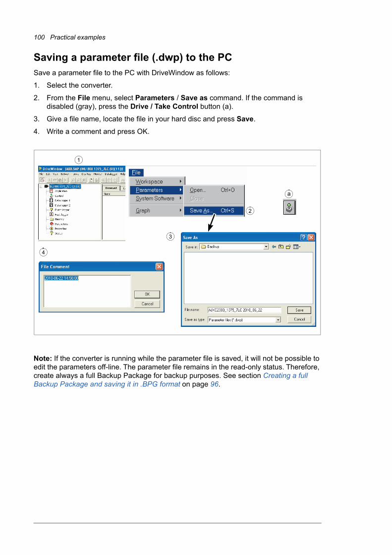
100 Practical examples
Saving a parameter file (.dwp) to the PCSave a parameter file to the PC with DriveWindow as follows:
1. Select the converter.
2. From the File menu, select Parameters / Save as command. If the command is disabled (gray), press the Drive / Take Control button (a).
3. Give a file name, locate the file in your hard disc and press Save.
4. Write a comment and press OK.
Note: If the converter is running while the parameter file is saved, it will not be possible to edit the parameters off-line. The parameter file remains in the read-only status. Therefore, create always a full Backup Package for backup purposes. See section Creating a full Backup Package and saving it in .BPG format on page 96.
2
3
a
1
3
4
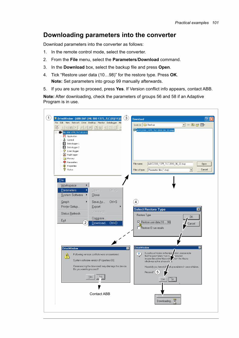
Practical examples 101
Downloading parameters into the converterDownload parameters into the converter as follows:
1. In the remote control mode, select the converter.
2. From the File menu, select the Parameters/Download command.
3. In the Download box, select the backup file and press Open.
4. Tick “Restore user data (10…98)” for the restore type. Press OK.
Note: Set parameters into group 99 manually afterwards.
5. If you are sure to proceed, press Yes. If Version conflict info appears, contact ABB.
Note: After downloading, check the parameters of groups 56 and 58 if an Adaptive Program is in use.
�
2
4
5
1
Contact ABB
3
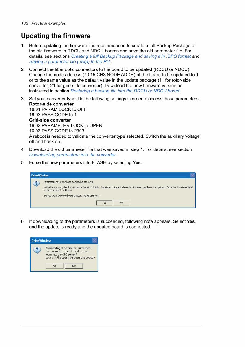
102 Practical examples
Updating the firmware1. Before updating the firmware it is recommended to create a full Backup Package of
the old firmware in RDCU and NDCU boards and save the old parameter file. For details, see sections Creating a full Backup Package and saving it in .BPG format and Saving a parameter file (.dwp) to the PC.
2. Connect the fiber optic connectors to the board to be updated (RDCU or NDCU). Change the node address (70.15 CH3 NODE ADDR) of the board to be updated to 1 or to the same value as the default value in the update package (11 for rotor-side converter, 21 for grid-side converter). Download the new firmware version as instructed in section Restoring a backup file into the RDCU or NDCU board.
3. Set your converter type. Do the following settings in order to access those parameters: Rotor-side converter16.01 PARAM LOCK to OFF16.03 PASS CODE to 1Grid-side converter16.02 PARAMETER LOCK to OPEN16.03 PASS CODE to 2303A reboot is needed to validate the converter type selected. Switch the auxiliary voltage off and back on.
4. Download the old parameter file that was saved in step 1. For details, see section Downloading parameters into the converter.
5. Force the new parameters into FLASH by selecting Yes.
6. If downloading of the parameters is succeeded, following note appears. Select Yes, and the update is ready and the updated board is connected.

Practical examples 103
If parameter download fails, an error note appears:
1. Compare the parameters to the parameter settings given in section Communication parameter settings.
2. Do the start-up checks and settings as instructed in chapters Start-up with low voltage stator and Start-up with medium voltage stator.
Communication parameter settings
Rotor-side converter
In addition, the fieldbus module settings must be made. See the ACS800-67(LC) doubly-fed induction generator control program firmware manual [3AUA0000071689 (English)].
Parameter Setting Note
16.20 GRID CONNECT MODE MCB1+MCB3/B
31.01 CROWBAR HW TYPE ACTIVE CB
2 ACTIVE CBs
In case of one crowbar
In case of two crowbars
70.15 CH3 NODE ADDR 11
70.21 CH4 NODE ADDR 11
97.01 DEVICE NAME INU 800 xxxx_7LC Use the correct converter type
99.27 MAX MEAS FLUX 2.43936
2.805279
Default value when using NUIM-62C board
To be set manually when using NUIM-10C board
99.28 MAX MEAS IS 32934116493965856585
Set according to power type. See also section NUIM-1x and NUIM-6x current measurements on page 79.

104 Practical examples
Grid-side converter
No. Name Factory setting
11.02 Q REF SELECT 2402
70.04 CH0 TIMEOUT 2000 ms
(When parameter is set to zero, time is not monitored.)
70.15 CH3 NODE ADDR 2
70.20 CH3 HW CONNECTION RING
71.01 CH0 DRIVEBUS MODE NO
90.01 D SET 10 VAL 1 701
90.02 D SET 10 VAL 2 2301
90.03 D SET 10 VAL 3 2402
90.04 D SET 12 VAL 1 15804
92.01 D SET 11 VAL 1 801
92.02 D SET 11 VAL 2 108
92.03 D SET 11 VAL 3 107
92.04 D SET 13 VAL 1 911
92.05 D SET 13 VAL 2 912
92.06 D SET 13 VAL 3 115
92.07 D SET 15 VAL 1 122
92.08 D SET 15 VAL 2 106
92.09 D SET 15 VAL 3 111
92.10 D SET 17 VAL 1 119
92.11 D SET 17 VAL 2 120
92.12 D SET 17 VAL 3 121
92.13 D SET 19 VAL 1 112
92.14 D SET 19 VAL 2 406
92.15 D SET 19 VAL 3 132
92.16 D SET 21 VAL 1 133
92.17 D SET 21 VAL 2 134
92.18 D SET 21 VAL 3 135
93.01 D SET 23 VAL 1 904
93.02 D SET 23 VAL 2 903
98.01 COMMAND SEL MCW
98.02 COMM MODULE CASCADE
99.08 AUTO LINE ID RUN NO (after start-up)

Practical examples 105
Changing the rotation direction of the generator
General
Terminal markings of the ABB generators for the stator (U, V, W) and rotor (K, L, M) are based on IEC 60034-8. The terminal markings are arranged so that the clockwise rotation is obtained when the alphabetical sequence of the letters (for example U1, V1, W1) corresponds to the time sequence of the system phase voltages. The phase sequence of the secondary winding (for example K, L, M) must correspond to the phase sequence of the primary winding (for example U, V, W). In counterclockwise rotation the time sequence of the system phase voltages are reversed by rearranging the grid cables (for example L2 and L3 in the case of 3-phase cabling). If the rotation direction of the generator is changed, U, V, W are changed to V, U, W. Respectively K, L, M are changed to L, K, M. Grid connections L1, L2, L3 connect to V, U, W and rotor connections U1, V1, W1 connect to L, K, M in counterclockwise rotation.
Clockwise rotation at drive end (D end)
Power cabinet
Encoder
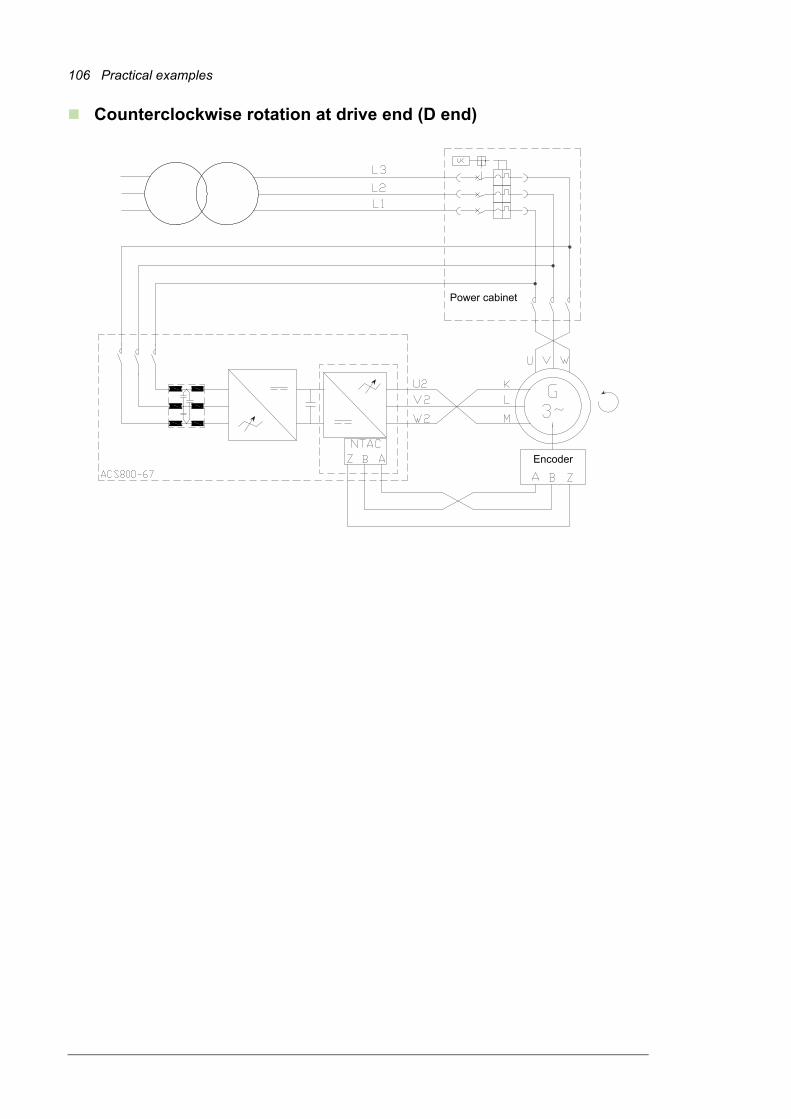
106 Practical examples
Counterclockwise rotation at drive end (D end)
Power cabinet
Encoder

Practical examples 107
Downloading the diagnostics of APBU branching unitAPBUDL is a tool program for APBU datalogger control and data upload. It is highly recommended to use the APBUDL program with the RUSB-01 adapter. With following instructions the datalogger file is downloaded for further analysis.
Program file is APBUDL.exe. These files are also needed in the same directory or in the system directory: Dwc_ddcp.dll, amctvb.dll, amctooli.dll.
Status:• No communication (No communication between PC and APBU board)
• APBU found (Communication OK, logic version of APBU board)
• Status (Status of loggers; if data collection is on: logging. If logger has triggered: data ready)
Commands:• u = Upload a logger
• t = Trig user logger
• l = Start user logger
• q = Quit
Data upload:• u = Upload a logger
• Define how many percent of the samples is uploaded (1…100)
• Define which logger is uploaded (F/L/U) [First/Last/User]
Following files will be created:
First Logger: first.csv
Last Logger: last.csv
User Logger: user.csv
Note: Files must be renamed.
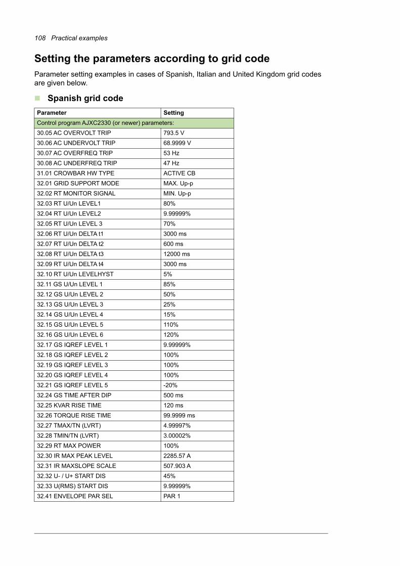
108 Practical examples
Setting the parameters according to grid codeParameter setting examples in cases of Spanish, Italian and United Kingdom grid codes are given below.
Spanish grid code
Parameter Setting
Control program AJXC2330 (or newer) parameters:
30.05 AC OVERVOLT TRIP 793.5 V
30.06 AC UNDERVOLT TRIP 68.9999 V
30.07 AC OVERFREQ TRIP 53 Hz
30.08 AC UNDERFREQ TRIP 47 Hz
31.01 CROWBAR HW TYPE ACTIVE CB
32.01 GRID SUPPORT MODE MAX. Up-p
32.02 RT MONITOR SIGNAL MIN. Up-p
32.03 RT U/Un LEVEL1 80%
32.04 RT U/Un LEVEL2 9.99999%
32.05 RT U/Un LEVEL 3 70%
32.06 RT U/Un DELTA t1 3000 ms
32.07 RT U/Un DELTA t2 600 ms
32.08 RT U/Un DELTA t3 12000 ms
32.09 RT U/Un DELTA t4 3000 ms
32.10 RT U/Un LEVELHYST 5%
32.11 GS U/Un LEVEL 1 85%
32.12 GS U/Un LEVEL 2 50%
32.13 GS U/Un LEVEL 3 25%
32.14 GS U/Un LEVEL 4 15%
32.15 GS U/Un LEVEL 5 110%
32.16 GS U/Un LEVEL 6 120%
32.17 GS IQREF LEVEL 1 9.99999%
32.18 GS IQREF LEVEL 2 100%
32.19 GS IQREF LEVEL 3 100%
32.20 GS IQREF LEVEL 4 100%
32.21 GS IQREF LEVEL 5 -20%
32.24 GS TIME AFTER DIP 500 ms
32.25 KVAR RISE TIME 120 ms
32.26 TORQUE RISE TIME 99.9999 ms
32.27 TMAX/TN (LVRT) 4.99997%
32.28 TMIN/TN (LVRT) 3.00002%
32.29 RT MAX POWER 100%
32.30 IR MAX PEAK LEVEL 2285.57 A
32.31 IR MAXSLOPE SCALE 507.903 A
32.32 U- / U+ START DIS 45%
32.33 U(RMS) START DIS 9.99999%
32.41 ENVELOPE PAR SEL PAR 1

Practical examples 109
Italian grid code
Parameter Setting
Control program AJXC2330 (or newer) parameters:
4.04 DEVICE ID INU 800 1160_7NC
20.23 USER KVAR LIMIT 100%
30.05 AC OVERVOLT TRIP 828
30.06 AC UNDERVOLT TRIP (2) (V) 69
30.07 AC OVERFREQ TRIP 53 Hz
30.08 AC UNDERFREQ TRIP 47 Hz
30.15 DLYED AC OV TRIP (V) 759
30.16 AC OV TRIP DLY (s) 1.5
31.01 CROWBAR HW TYPE ACTIVE CB
32.01 GRID SUPPORT MODE MAX. Up-p
32.02 RT MONITOR SIGNAL MIN. Up-p
32.03 RT U/Un LEVEL1 (1) 85%
32.04 RT U/Un LEVEL2 (4) 10%
32.05 RT U/Un LEVEL 3 (5) 75%
32.06 RT U/Un DELTA t1 (6) (ms) 800
32.07 RT U/Un DELTA t2 (3) (ms) 500
32.08 RT U/Un DELTA t3 (8) (ms) 2000
32.09 RT U/Un DELTA t4 (ms) 0 ms
32.10 RT U/Un LEVELHYST (7) 10%
32.11 GS U/Un LEVEL 1 90%
32.12 GS U/Un LEVEL 2 80%
32.13 GS U/Un LEVEL 3 25%
32.14 GS U/Un LEVEL 4 15%
32.15 GS U/Un LEVEL 5 110%
32.16 GS U/Un LEVEL 6 120%
32.17 GS IQREF LEVEL 1 0%
32.18 GS IQREF LEVEL 2 112%
32.19 GS IQREF LEVEL 3 112%
32.20 GS IQREF LEVEL 4 112%
32.21 GS IQREF LEVEL 5 -20%
32.22 GS IQREF LEVEL 6 -40%
32.23 GS AFTER DIP 0%
32.24 GS TIME AFTER DIP 0 ms
32.25 KVAR RISE TIME 50 ms
32.26 TORQUE RISE TIME 50 ms
32.27 Imax/In (LVRT) 124%
32.28 TMIN/TN (LVRT) 1%
32.29 Ip max/In (LVRT) 118%
32.30 IR MAX PEAK LEVEL 1777.66 A
32.31 IR MAXSLOPE SCALE 507.903 A
32.32 U- / U+ START DIS 80%
32.33 U(RMS) START DIS 10%
32.34 RT U/Un DELTA t5 (10) (s) 3
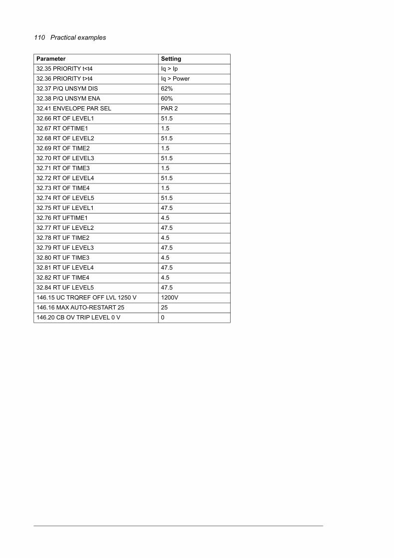
110 Practical examples
32.35 PRIORITY t<t4 Iq > Ip
32.36 PRIORITY t>t4 Iq > Power
32.37 P/Q UNSYM DIS 62%
32.38 P/Q UNSYM ENA 60%
32.41 ENVELOPE PAR SEL PAR 2
32.66 RT OF LEVEL1 51.5
32.67 RT OFTIME1 1.5
32.68 RT OF LEVEL2 51.5
32.69 RT OF TIME2 1.5
32.70 RT OF LEVEL3 51.5
32.71 RT OF TIME3 1.5
32.72 RT OF LEVEL4 51.5
32.73 RT OF TIME4 1.5
32.74 RT OF LEVEL5 51.5
32.75 RT UF LEVEL1 47.5
32.76 RT UFTIME1 4.5
32.77 RT UF LEVEL2 47.5
32.78 RT UF TIME2 4.5
32.79 RT UF LEVEL3 47.5
32.80 RT UF TIME3 4.5
32.81 RT UF LEVEL4 47.5
32.82 RT UF TIME4 4.5
32.84 RT UF LEVEL5 47.5
146.15 UC TRQREF OFF LVL 1250 V 1200V
146.16 MAX AUTO-RESTART 25 25
146.20 CB OV TRIP LEVEL 0 V 0
Parameter Setting

Practical examples 111
UK grid code
Parameter Setting
Control program AJXC2330 (or newer) parameters:
30.03 EARTH FAULT LEVEL 3
30.04 STATOR CURR TRIP 0 A
30.05 AC OVERVOLT TRIP 793.5 V
30.06 AC UNDERVOLT TRIP 0 V
30.07 AC OVERFREQ TRIP 53 Hz
30.08 AC UNDERFREQ TRIP 47 Hz
32.01 GRID SUPPORT MODE MAX. Up-p
32.02 RT MONITOR SIGNAL MIN. Up-p
32.03 RT U/Un LEVEL1 90%
32.04 RT U/Un LEVEL2 15%
32.05 RT U/Un LEVEL 3 80%
32.06 RT U/Un DELTA t1 1200 ms
32.07 RT U/Un DELTA t2 140 ms
32.08 RT U/Un DELTA t3 2500 ms
32.09 RT U/Un DELTA t4 140 ms
32.10 RT U/Un LEVELHYST 5%
32.11 GS U/Un LEVEL 1 90%
32.12 GS U/Un LEVEL 2 80%
32.13 GS U/Un LEVEL 3 25%
32.14 GS U/Un LEVEL 4 15%
32.15 GS U/Un LEVEL 5 110%
32.16 GS U/Un LEVEL 6 120%
32.17 GS IQREF LEVEL 1 0%
32.18 GS IQREF LEVEL 2 112%
32.19 GS IQREF LEVEL 3 112%
32.20 GS IQREF LEVEL 4 112%
32.21 GS IQREF LEVEL 5 -20%
32.22 GS IQREF LEVEL 6 -40%
32.23 GS AFTER DIP 0%
32.24 GS TIME AFTER DIP 0 ms
32.25 KVAR RISE TIME 50 ms
32.26 TORQUE RISE TIME 49.9988 ms
32.27 Imax/In (LVRT) 124%
32.28 TMIN/TN (LVRT) 0.999975%
32.29 Ip max/In (LVRT) 118%
32.30 IR MAX PEAK LEVEL 1777.68 A
32.31 IR MAXSLOPE SCALE 507.903 A
32.32 U- / U+ START DIS 80%
32.33 U(RMS) START DIS 9.99999%
32.34 RT U/Un DELTA t5 180 s
32.35 PRIORITY t<t4 Iq > Ip
32.36 PRIORITY t>t4 Ip > Iq
32.37 P/Q UNSYM DIS 62%

112 Practical examples
32.38 P/Q UNSYM ENA 60%
Control program IWXR7300 (or newer) parameters:
40.01 RT ENABLE ON
40.02 NAMU BOARD ENABLE ON
40.04 PHASE MEAS ENA ON
40.05 UAC CTRL SEL RMS VOLTAGE
40.09 RT U/Un MOD STOP 9.99999%
40.10 RT U/Un LEVEL1 90%
40.11 RT U/Un LEVEL2 0%
40.12 RT U/Un LEVEL3 70%
40.13 RT U/Un DELTA t1 3000 ms
40.14 RT U/Un DELTA t2 600 ms
40.15 RT U/Un DELTA t3 20000 ms
40.20 TRP VOLT PEAK 130%
40.21 TRP VOLT LEV 120%
40.22 TRP VOLT TIME 20 ms
40.23 TRP VOLT SEL RMS VOLTAGE
41.01 GRID SUPPORT MODE OFF
41.02 GS HIGHEST U ENA ON
41.03 GS U/Un LEVEL 1 100%
41.04 GS U/Un LEVEL 2 50%
41.05 GS U/Un LEVEL 3 25%
41.06 GS U/Un LEVEL 4 15%
41.07 GS IQREF LEVEL 1 0%
41.08 GS IQREF LEVEL 2 100%
41.09 GS IQREF LEVEL 3 100%
41.10 GS IQREF LEVEL 4 100%
Parameter Setting
Tracing the source of warnings, limits and faults 113
6
Tracing the source of warnings, limits and faults
What this chapter containsThis chapter describes the warnings, limits and faults of the converter and refers to descriptions of the warning and fault messages and LEDs given in other manuals.
WarningsAbnormal statuses are indicated by the warning words and messages.
LimitsThe converter control programs limit, for example, current, torque, power, speed and overvoltage. The performance of the limiters can be controlled by parameters.
Torque limit
The converter calculates shaft torque every 25 microsecond.
Torque is typically limited when• the limit defined by parameter 20.05 USER POS TORQ LIM is met
• some factor in the torque reference chain requires it.
Power limit
Parameters 20.17 P MOTORING LIM and 20.18 P GENERATING LIM define the maximum allowed power flows.

114 Tracing the source of warnings, limits and faults
FaultsThe converter protects itself with many functions. When a protection function is activated, the converter is immediately stopped (tripped) to avoid damages. A fault does not necessary mean that there is any material failure in the converter.
How to identify the fault and what to do in a specific fault situation
Both RMIO and NDCU board contains a fault logger. The latest faults and warnings are stored together with the time stamp at which the event was detected. The fault logger collects 64 of the most recent available pieces of information concerning faults (such as fault, warning, reset and system messages) into the fault buffer in the RAM memory. The latest 16 inputs are stored to the flash memory at the beginning of an auxiliary power supply loss if an internal +24 V power supply is used.
Both RMIO and NDCU board also contains data loggers 1 and 2. They are used to monitor signals and to store them for later retrieval and analysis. The contents of the data loggers are stored to the RAM memory.
The fault logger can be browsed in DriveWindow under the Fault tab and the data loggers under the Data logger tab. For more information, refer to DriveWindow user’s manual [3BFE64560981 (English)].
Compare the warning and fault messages of the fault logger to the messages listed in the firmware manual. Most warning and fault causes can be identified and corrected using the information in the fault tracing tables.
Before contacting ABB, see section Further information on page 12.
Warning and fault messagesRefer to • ACS800 IGBT supply control program firmware manual [3AFE68315735 (English)]
• ACS800 grid-side control program firmware manual [3AUA0000075077 (English)]
• ACS800-67(LC) doubly-fed induction generator control program firmware manual [3AUA0000071689 (English)].
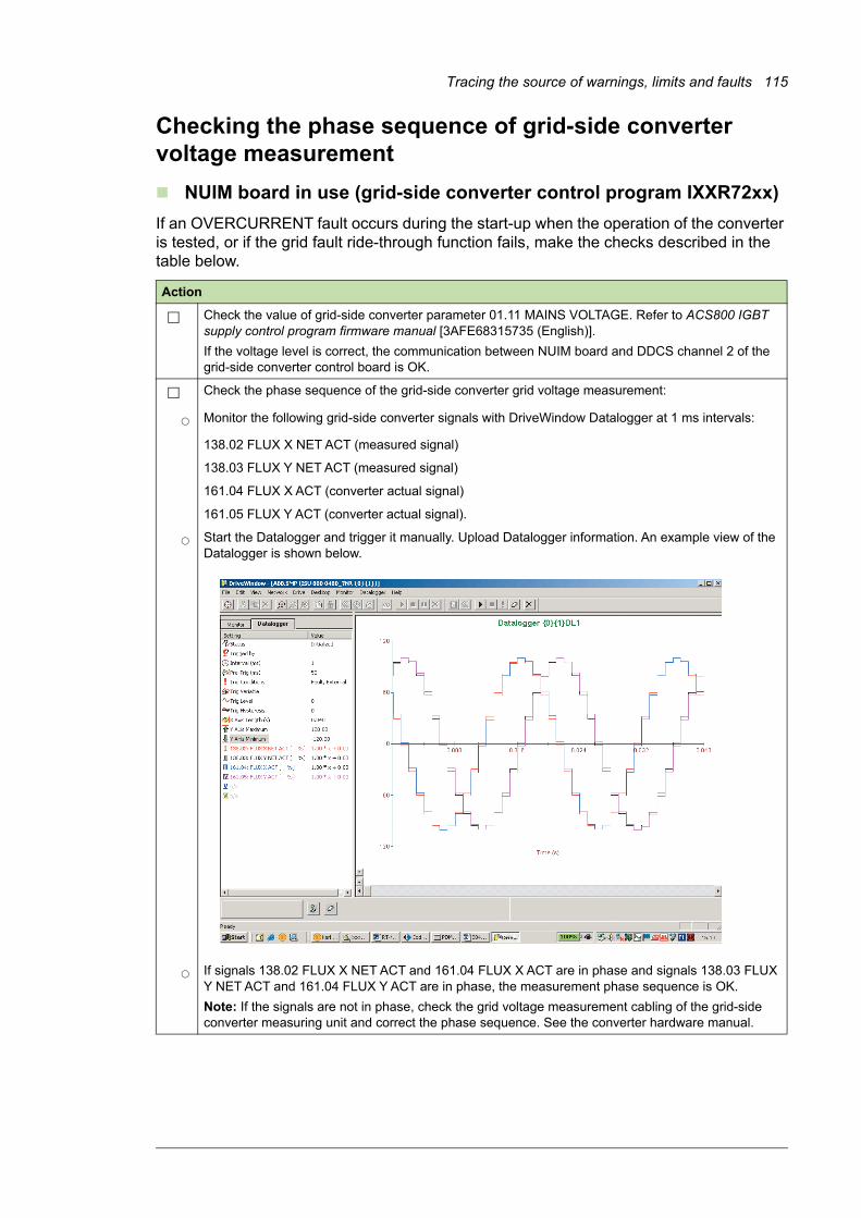
Tracing the source of warnings, limits and faults 115
Checking the phase sequence of grid-side converter voltage measurement
NUIM board in use (grid-side converter control program IXXR72xx)
If an OVERCURRENT fault occurs during the start-up when the operation of the converter is tested, or if the grid fault ride-through function fails, make the checks described in the table below.
Action
Check the value of grid-side converter parameter 01.11 MAINS VOLTAGE. Refer to ACS800 IGBT supply control program firmware manual [3AFE68315735 (English)].
If the voltage level is correct, the communication between NUIM board and DDCS channel 2 of the grid-side converter control board is OK.
Check the phase sequence of the grid-side converter grid voltage measurement:
Monitor the following grid-side converter signals with DriveWindow Datalogger at 1 ms intervals:
138.02 FLUX X NET ACT (measured signal)
138.03 FLUX Y NET ACT (measured signal)
161.04 FLUX X ACT (converter actual signal)
161.05 FLUX Y ACT (converter actual signal).
Start the Datalogger and trigger it manually. Upload Datalogger information. An example view of the Datalogger is shown below.
If signals 138.02 FLUX X NET ACT and 161.04 FLUX X ACT are in phase and signals 138.03 FLUX Y NET ACT and 161.04 FLUX Y ACT are in phase, the measurement phase sequence is OK.
Note: If the signals are not in phase, check the grid voltage measurement cabling of the grid-side converter measuring unit and correct the phase sequence. See the converter hardware manual.

116 Tracing the source of warnings, limits and faults
NAMU / BAMU board in use (grid-side converter control program IWXR74xx)
If an OVERCURRENT fault or GRID SYNC FAIL fault occurs during the start-up when the operation of the converter is tested, or if the grid fault ride-through function fails, make the checks described in the table below.
Action
Check the value of grid-side converter parameter 01.11 MAINS VOLTAGE. Refer to Grid-side control program for ACS800 wind turbine converters firmware manual [3AUA0000075077 (English)].
If the voltage level is correct, the communication between NAMU / BAMU board and DDCS channel 2 of the grid-side converter control board is OK.
Check the phase sequence of the grid-side converter grid voltage measurement:
Monitor the following grid-side converter signals with DriveWindow Datalogger at 1 ms intervals:
02.22 FLUX X NET ACT (measured signal)
02.23 FLUX Y NET ACT (measured signal)
02.20 FLUX X ACT (converter actual signal)
02.21 FLUX Y ACT (converter actual signal).
Start the Datalogger and trigger it manually. Upload Datalogger information. An example view of the Datalogger is shown below.
If signals 02.22 FLUX X NET ACT and 02.20 FLUX X ACT are in phase and signals 02.23 FLUX Y NET ACT and 02.21 FLUX Y ACT are in phase, the measurement phase sequence is OK.
Note: If the signals are not in phase, check the grid voltage measurement cabling of the grid-side converter NAMU / BAMU board and correct the phase sequence. See the converter hardware manual.
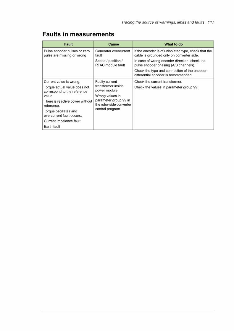
Tracing the source of warnings, limits and faults 117
Faults in measurements
Fault Cause What to do
Pulse encoder pulses or zero pulse are missing or wrong
Generator overcurrent fault
Speed / position / RTAC module fault
If the encoder is of unisolated type, check that the cable is grounded only on converter side.
In case of wrong encoder direction, check the pulse encoder phasing (A/B channels).
Check the type and connection of the encoder; differential encoder is recommended.
Current value is wrong.
Torque actual value does not correspond to the reference value.
There is reactive power without reference.
Torque oscillates and overcurrent fault occurs.
Current imbalance fault
Earth fault
Faulty current transformer inside power module
Wrong values in parameter group 99 in the rotor-side converter control program
Check the current transformer.
Check the values in parameter group 99.

118 Tracing the source of warnings, limits and faults

Further information
Product and service inquiries
Address any inquiries about the product to your local ABB representative, quoting the type designation and serial number of the unit in question. A listing of ABB sales, support and service contacts can be found by navigating to www.abb.com/searchchannels.
Product training
For information on ABB product training, navigate to new.abb.com/service/training.
Providing feedback on ABB manuals
Your comments on our manuals are welcome. Navigate to new.abb.com/drives/manuals-feedback-form.

Contact us
www.abb.com/windconverters
3AUA0000095094 Rev B (EN) 2017-12-31