1500 WATT WIND TURBINE - digimaxproducts.com WIND TURBINE Manual (2013-3...1500 WATT WIND TURBINE...
29
1500 WATT WIND TURBINE User’s Manual Ver.2013.3.2
Transcript of 1500 WATT WIND TURBINE - digimaxproducts.com WIND TURBINE Manual (2013-3...1500 WATT WIND TURBINE...

1500 WATT WIND TURBINE
User’s Manual
Ver.2013.3.2

2
TABLE OF CONTENT
1. SAFETY........................................................................................................................................................ 3
1.1 Mechanical Hazard ........................................................................................................................... 4
1.2 Electrical Hazard ............................................................................................................................... 4
2. MODEL AND SPECIFICATION TABLE ................................................................................................... 5
2.1 Specification Table ............................................................................................................................ 5
2.2 Performance specifications ............................................................................................................. 5
3. DIGITAL-CONTROLLED MPPT WIND POWER CHARGER .............................................................. 6
3.1 System wiring diagrams .................................................................................................................. 9
3.2 Mechanical Stop Switch ................................................................................................................ 12
4. PACKAGE CONTENTS ........................................................................................................................... 13
5. INSTALLATION PROCEDURE ............................................................................................................... 15
6. MAINTENANCE ........................................................................................................................................ 20
7. FAQS .......................................................................................................................................................... 20
8. WARRANTY .............................................................................................................................................. 23
APPENDIX A IMPORTANT SAFETY INSTRUCTIONS .......................................................................... 25
APPENDIX B BEAUFORT WIND SCALE ................................................................................................. 26
APPENDIX C BATTERY CONNECTION ILLUSTRATION ..................................................................... 27
APPENDIX D RECOMMENDED WIRE GAUGE ..................................................................................... 28
APPENDIX E REGISTRATION FORM ...................................................................................................... 29

3
1. SAFETY
Your 1500 Watt Wind Turbine is designed with your personal safety as the first priority. However, there are still some inherent dangers involved with any electrical and/or mechanical equipment. Safety must be the primary concern as you plan the location, installation and operation of the Turbine. Please read the following: Important Safety Instructions Please take the time to read through this manual prior to assembly.
1) Place this instruction manual in a safe place for reference. 2) Wait until a calm day to install or perform maintenance on your Turbine with activation of MPPT brake
or mechanical stop switch. 3) Listen to your Turbine should you hear any mechanical noise, maintenance may be required, please
contact your Turbine dealer. 4) After installation re-adjust and tighten the screws and bolts. 5) Adhere to proper grounding techniques as established by the NEC. 6) Your Wind Turbine must be installed in accordance with this manual and local and national building
code. Incorrect installation may void your warranty. 7) Wind Turbine blades spin at a potentially dangerous speed this must be respected. Never approach a
Turbine in motion. 8) Note wire size (gauge chart included) prior to wiring. Any under sizing of wire can be potentially
dangerous. 9) Check the manual brake health periodically. We suggest that the users turn on the manual brake of
MPPT to see if the speed is getting low. Meanwhile, the RED LED should be illuminated once the manual brake is turned on. If you hear the sound of the relay, it means the MPPT works normally.
10) Check the three wires from the Turbine output periodically. Please use a current clamp meter to measure AC current. If the outputs are not consistent, please contact the distributor for further instruction. For safety reasons, please stop operating your Turbine.
11) Check the battery health periodically. The abnormal battery and improper connection will cause over-spin issues. The Turbine’s operation should be halted to reduce the risk of damage due to over spin of the rotor blades.
12) Operating Environment: A. Operating Temperature: -4°F (-20°C) ~ 122°F (50°C)
B. Operating Humidity: < 80% C. Average Wind Speed: < 30MPH (<13 m/s or <48KMH) D. Max. Peak Wind Speed: < 45MPH (<20m/s or <70KMH) E. Elevation: < 1000m F. Applicable Installation Height: 8.85ft〜33ft (2.7m〜10m)
It is subject to IEC 61400-2 safety standards. If the operating temperature and wind speed exceed the above-mentioned limits, please turn on the manual brake in proper way to shut off the Wind Turbine.
4
1.1 Mechanical Hazard Rotating blades present the most serious mechanical hazard. The rotor blades are made of very strong thermoplastic and glass fiber. At the tip, the blades may be moving at velocities over 60m/s. At this speed, the tip of a blade is nearly invisible and can cause serious injury. Under no circumstances should you install the Turbine where a person could come in contact with moving rotor blades.
1.2 Electrical Hazard The 1500W Turbine is equipped with sophisticated electronics designed to provide protection from electrical dangers. Please note that the inherent personal dangers from electrical current still exist, therefore caution should always be used when connecting this and other electrical devices. Heat in a wiring system is often a result of too much current flowing through an undersized wire or through a bad connection. Please consult wire guide table below. Batteries can deliver a dangerous amount of current. If a short circuit occurs in the wiring from the batteries, a fire can result. In order to avoid this threat, a properly sized fuse or circuit breaker is required in the lines connecting to the battery.
Choosing your 1500 Watt Wind Turbine’s location Prior to the mounting of your 1500 Watt Wind Turbine, you must carefully consider a location. Things to consider when thinking about your location
A) Distance from any obstacles that will cause turbulence, trees, buildings etc. Locate your Turbine in windy sites so as not to disturb neighbors and animals around. The noise
and vibration element cannot be got rid of even if 1500 Watt Wind Turbine offers the lowest noise than any others on the market. The better location of your Turbine requires avoiding personnel or animal activities within a 33 ft. (10 m) radius, and human habitation and wildlife within a 66 ft. (20 m) radius.
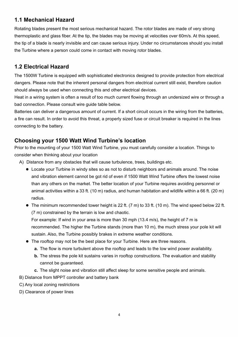
The minimum recommended tower height is 22 ft. (7 m) to 33 ft. (10 m). The wind speed below 22 ft. (7 m) constrained by the terrain is low and chaotic. For example: If wind in your area is more than 30 mph (13.4 m/s), the height of 7 m is recommended. The higher the Turbine stands (more than 10 m), the much stress your pole kit will sustain. Also, the Turbine possibly brakes in extreme weather conditions.
The rooftop may not be the best place for your Turbine. Here are three reasons. a. The flow is more turbulent above the rooftop and leads to the low wind power availability. b. The stress the pole kit sustains varies in rooftop constructions. The evaluation and stability
cannot be guaranteed. c. The slight noise and vibration still affect sleep for some sensitive people and animals.
B) Distance from MPPT controller and battery bank C) Any local zoning restrictions D) Clearance of power lines
2. M
2.1 Mod
Rela
Rela
Volt
Roto
Star
Cut-
Surv
Num
Blad
Sug
※
※
2.2Thesmobetw
MODEL A
Specific
del
ated Speed
ated Power
tage with M
or Diamete
rt-up Wind S
-in Wind Sp
vival Wind S
mber of Blad
de Material
ggest Batter
The mechaSurvival wswitch is tu
2 Performe following pooth, steadyween powe
AND SPE
cation Ta
d
r
PPT
r
Speed
peed
Speed
des
ry Capacity
anical stop ind speed murned on. E
mance sppower curvey wind speer and curren
ECIFICA
able
150
14 m
150
24V
1.7
>1 m
2.5
60 m
3
Plas
>20
switch shoumeans that
Exceeding th
pecificatie shows theed, you can nt use the fo
TION TA
00W Turbine
m/s (31.3mp
0W
V
m (5.58ft)
m/s
m/s (5.59 m
m/s (134.2 m
stic compou
00 A/Hr.
uld be turnethe Wind Tu
his stated w
ions e performan
expect to sollowing for
5
ABLE
e
ph) (45.9 ft.
mph) (8.2 ft.
mph) (196.8
und with gla
ed on when urbine will s
wind speed w
nce you shosee output rrmula:
./s)
./s)
85 ft./s)
ass fiber
the wind spsurvive 134will result in
uld expect fresembling
peed upwar.2 MPH wh
n Wind Turb
from your Wthe curve ill
rds 40 MPHen the mec
bine failure a
Wind Turbinlustrated be
H (65 KMH)chanical stoand collaps
e. During elow. To con
. p e.
nvert

6
POWER = VOLTAGE × AMPS
3. DIGITAL-CONTROLLED MPPT WIND POWER CHARGER
Please see included Manual for your MPPT Charge Controller. MCU fully digital-controlled MPPT wind power charger Boost/Buck conversion, large DC input voltage range Smart load management function, braking function
MPPT Specification Table
Rated Output Power 1500W Max.
Battery Voltage Range 15〜35VDC (For 24VDC battery system)
Input Voltage Range 5~75 Vrms
Charger Efficiency 95% Max.
Battery Protection Voltage 29.5±1VDC (Lead-acid batteries) 31V±1VDC (Deep cycle batteries)
Rated Load Current Hi: 40A (Max.45A) / Lo: 20A (Max. 22A)
Over-Speed Braking <1400 RPM

7
LED indication Light Indications Status GREEN light on Power on (working normally)
Charge/Discharge GREEN light on Charging (power from Turbines)
Charge/Discharge GREEN light flashes
Discharging (power from battery)
Protection RED light flashes Once Over-speed protection
Twice High battery voltage protection
Three times Over total current protection (input and output)
Four times Over charging current protection
Five times Overheat protection for MPPT
Six times Low battery
Seven times Manual brake on
Eight times Overheat protection for generator
Nine times Acceleration auto brake protection
Remark: When the auto protections above occur, the braking will last 3 minutes before Turbines start again. Caution 1: Any under sizing of wire can be potentially dangerous; our warranty doesn’t cover damage caused by improper use of wire gauge. Caution 2: Please review the following wire gauge table to install the correct wire gauge. We recommend these as the minimum wire sizes for the distance from the MPPT and your turbine for optimal performance. Always use the largest gauge wires that are practical and affordable. Local, state, and or national electrical codes take precedence over these general recommendations.
24 Volt System, AWG / Metric Wire Size mm2
Number of
Turbines:
0-30 ft.
(0-9 m)
30-60 ft.
(9-18 m)
60-90ft
(18-27 m)
90-150 ft.
(27-46 m)
150-190 ft.
(46-58 m)
190-250 ft.
(58-76 m)
250-310ft
(76-95 m)
310-390 ft.
(95-119 m)
390-500ft
(119-152 m)
1 14/2.5 mm2 12/4 mm2 10/6 mm2 8/10 mm2 6/16 mm2 4/25 mm2 4/25 mm2 000/90 mm2 000/90 mm2
2 12/4 mm2 8/10 mm2 6/16 mm2 4/25 mm2 4/25 mm2 2/35 mm2 2/35 mm2 1/50 mm2 0/50 mm2
3 10/16 mm2 8/10 mm2 6/16 mm2 4/25 mm2 2/35 mm2 2/35 mm2 1/50 mm2 0/50 mm2 00/70 mm2

8
System protection (see also included manual) Your MPPT charge controller, equipped with sensors inside the unit, comes with four main protection functions. Self-protection: The MPPT charge controller has a temperature sensor. Temperature of the internal circuitry is moderated by an internal fan that is activated at 45°C (110°F).When the temperature exceeds 65°C (150°F), the MPPT will apply both the fan and braking system to prevent damage. Protection for Battery: The MPPT charge controller can sense the voltage of battery and the current output/input to battery. If the parameter of voltage and current is wrong, then the braking system will be turned on. Protection for Wind Turbine: The MPPT charge controller can sense the rotation speed of Wind Turbine. If the rotation speed is over the setting value in program, the braking system will be turned on. The latest version of MPPT charger controller is also equipped the phase detector technology. If the AC output wave from generator is incorrect, that means the generator may be damaged. At that moment, the MPPT will apply the braking system and the LED lamp to warn users. Protection for No Battery Connection: When the MPPT charge controller shuts down due to the abnormal battery and improper connection; it will cause free-spin issues. At 150 RPM and above, the MPPT charge controller should apply the braking system automatically and the power from the Wind Turbine should be cut off at once. The Wind Turbine will turn on and brake repeatedly. Under safety condition, please check the battery wire and function as soon as possible.

3.1Theava
Sin
Systemere are multilable comp
ngle Turb
m wiring diple options
ponents.
bine inst
diagramss to connect
tallation:
s t your Wind
9
NOTE: Pwire gaugwire size
NOTE: PSwitch siSEC. 3.2
d Turbine de
Please refer ge table andfor your sy
Please applymultaneous
2 for detailed
ependent on
to the recod select thestem.
y the Mechasly. Refer tod info.
n your powe
ommended e appropriat
anical Stop o the
er requirem
te
ents and

Mu
ultiple Tuurbine insstallationn:
10
NOTwirewire
NOTSwiSEC
TE: Please e gauge tabe size for yo
TE: Please tch simultan
C. 3.2 for de
refer to thele and selec
our system.
apply the Mneously. Reetailed info.
e recommenct the appro
Mechanical efer to the
nded opriate
Stop

Hy
A tyWhe
ybrid Sola
ypical “hybrienever feas
ar/Wind
d” system (sible wire th
System:
(Photovoltaihe Turbine a
:
ic and Windand solar pa
11
NOwirwir
NOSwSE
d combinedanels to the
OTE: Pleasere gauge tare size for y
OTE: Pleasewitch simultaEC. 3.2 for d
) is wired asir own set o
e refer to thble and sele
your system
e apply the aneously. Rdetailed info
s follows. of battery te
he recommeect the app
m.
MechanicaRefer to the o.
erminals.
ended ropriate
al Stop

12
3.2 Mechanical Stop Switch The MPPT controller has an integrated battery controlled braking mechanism. This is explained in your MPPT manual. Further to this protection we have incorporated a secondary level of safety and convenience with a mechanical 3-phase AC brake. During periods of high winds (upwards of 40 mph, 17m/s) it is strongly advised to utilize your MPPT brake or your mechanical stop switch. The use of your mechanical stop switch will not affect the voltage of your battery. We strongly advise the activation of the mechanical stop switch during any maintenance of or around your Turbine. This will prevent the blades spinning and voltage to be transferred. Likewise during initial installation please activate the mechanical brake. The final step in installation of Turbine, controller, and battery should be release of this mechanical stop switch. The mechanical stop switch is pre-wired for your convenience with 10 AWG wire and battery terminal connections. The wire configuration is explained in the diagram below (fig 1). Place the corresponding wires (red, black, blue) from the mechanical stop switch into the MPPT input terminals. This should match the similar colored wires from your Turbine. Your Turbine and stop switch share input terminals on the MPPT. This provides a parallel connection. Test the connection of your mechanical stop switch at the point of initial installation. Push the brake “ON”. You should see the Turbine stop its rotation. Continue to apply this brake during the remainder of your installation. Should the Turbine continue to spin, check your terminal connections. Do not approach the Turbine without activation of this mechanical stop switch under any circumstance!
Notes
• It is not necessary to apply MPPT brake during activation of the mechanical stop switch.
• It is strongly advised to test both mechanical and MPPT stop switch periodically.
• Your mechanical stop switch is pre-wired with 10 AWG wire, this should not be altered.
• The mechanical stop switch should be placed close
to your MPPT in a dry ventilated environment.
• For multiple Turbine applications please use one mechanical stop switch for each Wind Turbine.
• This mechanical stop switch has been designed specifically for your Wind Turbine; it should not be incorporated into other models.
Figure 1

13
4. PACKAGE CONTENTS
Check the parts listed with the contents of the box and make sure that you have everything needed for assembly.
Caution: The edges of the blades are sharp. Please handle with care.

14
Name Quantity
Turbine 1
Blade 3
MPPT Charger Controller 1
Hub 1
Vertical Tail 1
Nose Cone 1
Amp Meter 1
Brake Switch (Mechanical Stop Switch) 1
Accessory Pack
Special Sleeve (M16) 1
Hex Screw (M5XL50) 1
Hex Screw (M8XL40) 6
Hex Screw (M5XL20) 4
Set Screw (M8XL12) 4
Locking Nut (M8) 6
Spacer (M16) 1
Spacer (M8) 12
Spacer for Vertical Tail 4
Hex Key No.3 1
Hex Key No.4 1
Hex Key No.6 1
Replacement
Accessory Pack
Hex Screw (M5XL50) 1
Hex Screw (M8XL40) 6
Hex Screw (M5XL20) 4
Locking Nut (M8) 6
Spacer (M8) 12
Spacer (M16) 1
Spacer for Vertical Tail 4
Set Screw (M8XL12) 4

15
5. INSTALLATION PROCEDURE
Step 1: Open box to ensure all parts are present, remove the hub from the box.

16
Step 2: Take out the blades from box and fasten the blades on hub with nuts. Caution: There is a blue dot on hub and blade. Please ensure the dots are installed at the same side.
Caution: Make sure that all of the bolts are secured with nuts and the dots all in the correct direction.
17
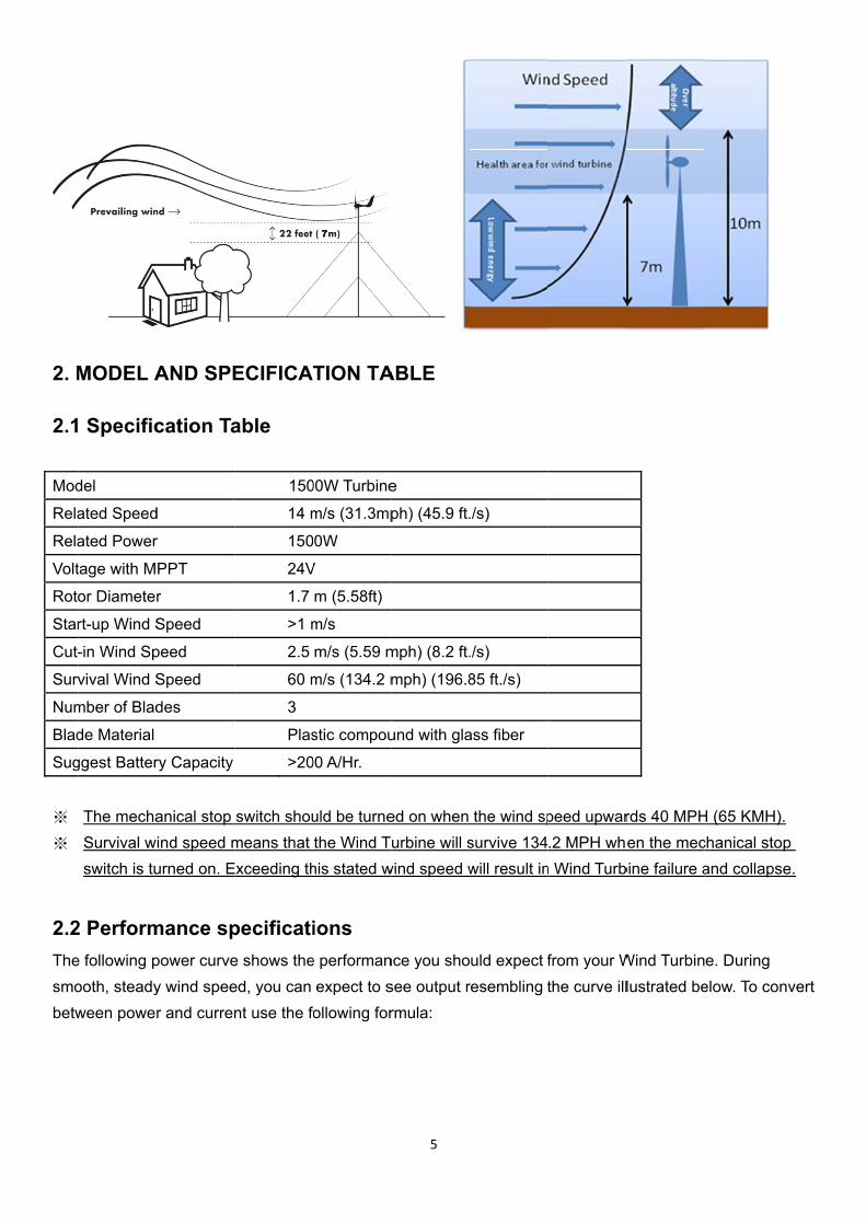
Step 3: How to install the hub.
Caution: Make sure the blue dots all face to the operator.
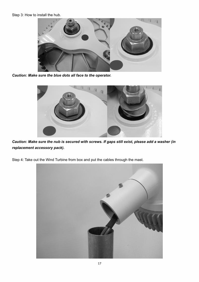
Caution: Make sure the nub is secured with screws. If gaps still exist, please add a washer (in replacement accessory pack). Step 4: Take out the Wind Turbine from box and put the cables through the mast.

18
Step 5: To install the Wind Turbine to your chosen tower (not included) securely fasten the bolt by using the hex wrench. Caution: Owing to the base of the Turbine, the outside diameter of the iron pipe should be 48.3mm to 48.6mm and the wall thickness should be 1.9mm at least.
Step 6: Put the sleeve inside the nose cone and fasten the nose cone to the hub. Apply pressure to the connections to ensure a secure fit.

19
Step 7: Tail Fin assembly. Use the four supplied spacers and HEX screws, to firmly connect the tail fin to the hub.
Step 8: Final product diagram

20
6. MAINTENANCE
Your 1500 Watt Wind Turbine has been designed to run for long periods without requiring any maintenance. Performance will be enhanced if you periodically inspect your system. Review the following simple maintenance procedures and implement every six months. Caution 1: Do not go near the Wind Turbine during operation. Caution 2: The blades are sharp. Please handle with care.
• Check blades for superficial damage. Replace blades if damaged. It is important to not use blades that are damaged, as you will lose overall balance, resulting in a decrease in efficiency. Should you notice damage to the blades you must replace all 3. The blades are balanced as sets.
• Check the blade bolts and the hub nut for tightness. • Check nosecone for cracks and tighten nuts. • Wipe any excess dirt build-up from the blades. • Check all electrical connections to make sure they are tight and free from corrosion. • Check the voltage of your battery bank with a Multi-meter and clean the terminals. • We suggest replacing the blades every five years for optimal performance
7. FAQS
(1) How does the 1500 Watt Wind Turbine control power and RPM in high winds? Your Turbine’s operation will be halted to reduce the risk of damage due to overcharge and over spin of the rotor blades. This process of braking is handled internally through your Turbine electronics.
(2) What is the maximum wind speed the 1500 Watt Wind Turbine will survive, and do need to take it down
in a storm? Your Wind Turbine is designed to operate in most climatic conditions. Should you expect or experience winds of 150MPH upwards, please turn off the MPPT controller which will in turn manually apply the braking system to protect from any over spin. Once the Turbine has stopped it is possible to lay down the Tower to offer further protection.
(3) How long will be the bearings or other wearing parts last?
According to engineering calculations, the bearings should have a 10-year life span in 12- mph (6 m/s) average wind speed sites. Bearing life will vary from one application to another; however, you should expect at least a five-year performance in adverse conditions and 10 years in normal conditions.
(4) Can the 1500 Watt Wind Turbine be connected in reverse-polarity to the battery without causing any
damage? Reverse polarity will cause damage to both your MPPT controller and battery if not quickly remedied. Always double check any wiring to reduce the risk of reverse polarity. Your Turbine is equipped with
(5)
(6)
(7)
(8)
•P
polarity prodamage to Reverse poto prevent Mparts inside Will it hurt mNo, the 150relay. The fshort-circui
Where can Your 1500 WShould youThis should
What is theGenerally alosses as c
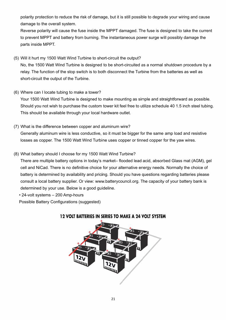
What batteThere are mcell and NiCbattery is dconsult a lodetermined 24-volt sys
Possible Ba
otection to rethe overall
olarity will caMPPT and e MPPT.
my 1500 Wa00 Watt Winfunction of tt the output
I locate tubWatt Wind T
u not wish tod be availab
e difference aluminum wcopper. The
ry should I multiple battCad. There etermined b
ocal battery d by your usstems – 200attery Config
educe the rsystem. ause the fubattery from
att Wind Tund Turbine ithe stop swt of the Turb
bing to makTurbine is do purchase tble through
between cowire is less c
1500 Watt
choose for tery optionsis no defini
by availabilisupplier. O
se. Below is0 Amp-hourgurations (s
isk of dama
se inside thm burning. T
urbine to shos designed itch is to bobine.
e a tower?designed to the custom your local h
opper and aconductive, Wind Turbi
my 1500 Ws in today’s tive choice ity and prici
Or view: wwws a good guis
suggested)
21
age, but it is
he MPPT daThe instanta
ort-circuit th to be short
oth disconne
make moutower kit fe
hardware ou
aluminum wso it must bne uses co
Watt Wind Tumarket– flofor your alt
ing. Shouldw.batterycoideline.
s still possib
amaged. Thaneous pow
he output?t-circuited aect the Turb
nting as simeel free to ututlet.
wire? be bigger fopper or tinn
urbine? ooded lead ternative enyou have q
uncil.org. T
ble to degrad
he fuse is dewer surge w
as a normal bine from th
mple and strtilize schedu
or the samened copper f
acid, absorbergy needs
questions rehe capacity
de your wir
esigned to twill possibly
shutdown pe batteries
raightforwaule 40 1.5 in
e amp load afor the yaw
rbed Glass ms. Normally egarding bay of your ba
ring and cau
take the curdamage the
procedure bas well as
rd as possibnch steel tu
and resistiv wires.
mat (AGM),the choice
atteries pleattery bank i
use
rrent e
by a
ble. ubing.
e
, gel of
ase s
(9)
(10)
(11)
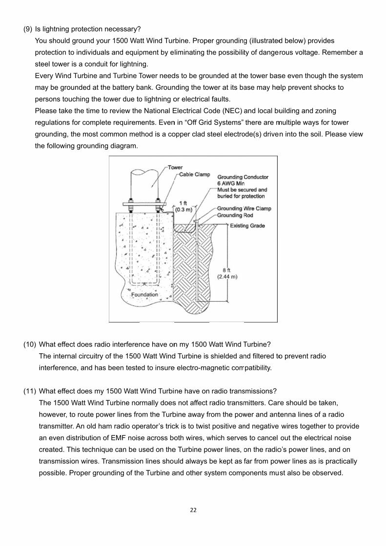
Is lightning You shouldprotection tsteel tower Every Windmay be gropersons touPlease takeregulationsgrounding, the followin
) What effecThe interninterferenc
) What effecThe 1500 however, t transmittean even d created. T transmiss possible. P
protection ground youto individuais a condui
d Turbine anounded at thuching the te the time to for complethe most co
ng groundin
ct does radnal circuitry ce, and has
ct does my Watt Wind to route pow
er. An old hadistribution oThis techniqion wires. TProper grou
necessary?ur 1500 Wals and equipit for lightninnd Turbine The battery btower due too review the
ete requiremommon metg diagram.
io interferenof the 1500
s been teste
1500 Watt Turbine no
wer lines froam radio opof EMF noisue can be u
Transmissiounding of th
? att Wind Turpment by eng. Tower need
bank. Grouno lightning oe National E
ments. Eventhod is a co
nce have on0 Watt Winded to insure
Wind Turbirmally doesom the Turberator’s tric
se across boused on then lines shou
he Turbine a
22
rbine. Propeliminating th
ds to be gronding the towor electricalElectrical Con in “Off Gridopper clad s
n my 1500 Wd Turbine is e electro-ma
ne have ons not affect bine away frck is to twistoth wires, w
e Turbine pould always and other sy
er groundinghe possibilit
unded at thwer at its ba faults. ode (NEC) d Systems”steel electro
Watt Wind Tshielded an
agnetic com
radio transradio transmrom the powt positive anwhich serveower lines, obe kept as fystem comp
g (illustratedty of dange
e tower basase may he
and local buthere are m
ode(s) drive
Turbine? nd filtered topatibility.
smissions? mitters. Carwer and antnd negative s to cancel on the radiofar from pow
ponents mu
d below) prrous voltag
se even thoelp prevent s
uilding and multiple wayn into the s
o prevent ra
re should betenna lines wires togetout the ele
o’s power linwer lines asst also be o
ovides e. Rememb
ough the sysshocks to
zoning ys for tower oil. Please v
adio
e taken, of a radio ther to provctrical noisenes, and ons is practicaobserved.
ber a
stem
view
vide e n ally

23
(12) Will it affect the regulation of my 1500 Watt Wind Turbine to install an RF (radio frequency) filter? An RF filter should not affect the regulation of the Turbine, but any electronic devices placed in line with the Turbine must be rated for the proper current and voltage. It is best to place any line filters on the power lines for the load device that requires it, and as close to the device as possible.
TROUBLE SHOOTING You may require an extra person to assist with these tests.
1) Remove the blade/hub from the Turbine. Replace the rotor hub nut on the rotor shaft. 2) Quickly spin the rotor shaft manually with your fingers while connecting and disconnecting the red and
black wires (Turbine must not be connected to batteries). 3) With the red and black wires connected to each other, the shaft should be more difficult to turn. When
the wires are disconnected it should spin freely. Should this not be true please contact your Turbine dealer.
4) With your 1500 Watt Wind Turbine connected to your battery bank, use an electric hand drill to spin the rotor shaft.
5) Below 150 RPM, the rotor should spin freely.
6) At 150 RPM and above, the Wind Turbine should be charging the battery. You should feel resistance on the rotor shaft if the shaft is not rotating; contact your Turbine dealer. Be aware your battery banks needs to be under 24V for this testing as the Turbine needs to read a charge.
8. WARRANTY
We warrant your product to be free from defects in material and/or workmanship for a period of 1 year from original date of purchase. Warranty coverage is extended only to customer (original purchaser). If product proves defective during warranty period, the manufacturer, at its option will:
1. Replace Wind Turbine with new or refurbished product. 2. Correct reported problem
Customers warranty continues to be valid on repaired or replaced product from original warranty date.
Restrictions This warranty covers defects in manufacturing discovered while using the product as recommended by the manufacturer. The warranty does not apply to a) equipment, materials, or supplies not manufactured by the manufacturer. b) Product that has been modified or altered other than by the manufacturer or without prior manufacturer’s approval. c) Has been exposed to winds exceeding 134mph d) Windstorms, lightning and Hail damage e) Repairs performed by other than authorized support staff. f) All acts of God; misuse, negligence or accidents. g) Tower foundation and wire has not been installed, operated, repaired or maintained in accordance with the instructions supplied by manufacturer. Any service identified in the above list or product is found not to have any defect in manufacturers’ workmanship or materials the customer will be responsible for the costs of all repairs and expenses incurred by the manufacturer.

24
Disclaimer EXCEPT FOR THE EXPRESSED WARRANTY SET FORTH ABOVE, THE MANUFACTURER DISCLAIMS ALL OTHER EXPRESSED AND IMPLIED WARRANTIES, INCLUDING THE IMPLIED WARRANTIES OR FITNESS FOR A PARTICULAR PURPOSE, MERCHANTABILITY AND NON-INFRINGEMENT. NO OTHER WARRANTY, EXPRESSED OR IMPLIED, WHETHER OR NOT SIMILAR IN NATURE TO ANY OTHER WARRANTY PROVIDED HEREIN, SHALL EXIST WITH RESPECT TO THE PRODUCT SOLD UNDER THE PROVISIONS OF THESE TERMS AND CONDITIONS. THE MANUFACTURER EXPRESSLY DISCLAIMS ALL LIABILITY FOR BODILY INJURIES OR DEATH THAT MAY OCCUR, DIRECTLY OR INDIRECTLY, BY USE OF THE PRODUCT BY ANY PERSON. ALL OTHER WARRANTIES ARE EXPRESSLY WAIVED BY THE CUSTOMER. Warranty Claims & Return Policies To be eligible for service under this warranty, customer must either contact manufacturer either through written request or by telephone to submit a service request for the Wind Turbine covered by this warranty within specified period (1 year from original date of purchase) and request a return authorization (RA) number, This RA # must be issued before any product can be returned. All notifications must include the following information:
a) Description of alleged defect b) How the Wind Turbine was being used c) Serial # d) The original purchase date e) Name, phone #, address of party requesting warranty
Within 2 to 3 business days the manufacturer will provide the customer with an RA# and will direct customer to location where the product is to be returned. Once an RA has been issued the customer has 30 days to return the product. Failure to deliver the product within the 30 days results in the RA as no longer being valid and a new RA must be issued. Manufacturer is under no obligation to accept any product that is returned to them without a proper RA #. Limitation of Liability UNDER NO CIRCUMSTANCES WILL THE MANUFACTURER OR ITS AFFILIATES OR SUPPLIERS BE LIABLE OR RESPONSIBLE FOR ANY LOSS OF USE, INTERRUPTION OF BUSINESS, LOST PROFITS, LOST DATA, OR INDIRECT, SPECIAL, INCIDENTAL, OR CONSEQUENTIAL DAMAGES OF ANY KIND REGARDLESS OF THE FORM OF ACTION, WHETHER IN CONTRACT, TORT (INCLUDING NEGLIGENCE), STRICT LIABILITY OR OTHERWISE, RESULTING FROM THE DEFECT, REPAIR, REPLACEMENT, SHIPMENT OR OTHERWISE, EVEN IF THE MANUFACTURER OR ITS AFFILIATE OR SUPPLIER HAS BEEN ADVISED OF THE POSSIBILITY OF SUCH DAMAGE.

AP
Reaacc1.
2.
For highTurb
3.
4.
5.
6.
7.
PPENDIX
ad these insidents. PleaLocate youand vibratioothers on thactivities wThe height constrainedexample: If
her the Windbine possib
The rooftopa. The flob. The st
be guac. The sl
Check the mMPPT to semanual braCheck the tmeasure ACFor safety rCheck the bover-spin isover spin oSurvival winbrake is tur
X A IMPO
structions bease also mar Wind Turb
on element he market. Tithin a 33 ft of installati
d by the terrf winds in yod Turbine sly brakes in
p may not bow is more tress the poaranteed. ight noise amanual braee if the speake is turnedthree wires C current. Ifreasons, plebattery heassues. The f the rotor bnd speed mrned on. Ex
RTANT S
elow beforeake sure it isbine in windcannot be gThe better l(10 m) rad
on should brain is low aour area aretands (more
n extreme w
e the best pturbulent ab
ole kit susta
and vibratioke health peed is gettind on. If you from the Wf the outputease stop olth periodicWind Turbin
blades. means that tceeding this
SAFETY
e installing ys set up und
dy sites so agot rid of evlocation of yius, and hube 22 ft (7 mand chaotice more thane than 10 m
weather con
place for yobove the roins varies in
n still affecteriodically.
ng low. Meahear the so
Wind Turbines are not co
operating yoally. The abne’s operat
the wind turs stated win
O
A
B
C
D
E
F.
It
te
tu
25
INSTRU
your Wind Tder environas not to disven if Sunforyour Wind Tman habita
m) to 33 ft (1. n 30 mph (1m), the much
ditions.
our Wind Tuoftop and len rooftop co
t sleep for sWe sugges
anwhile, theound of the e output peronsistent, pour Wind Tubnormal bation should b
rbine will sund speed w
Operating En
A. Operating T
B. Operating
C. Average W
D. Max. Peak
E. Elevation: <
. Applicable
t is subject to
emperature a
urn on the ma
UCTIONS
Turbine to emental and
sturb neighbrce Wind TuTurbine requation and wi10 m). The
3.4 m/s), thh stress you
rbine. Hereeads to the onstructions
some sensitst that the ue RED LED
relay, it meriodically. Please conta
urbine. ttery and imbe halted to
rvive 157 Mill result in w
nvironment:
Temperature
Humidity: < 8
Wind Speed: <
k Wind Speed
< 1000m
Installation H
o IEC 61400-
and wind spe
anual brake
nsure peop operating c
bors and anurbine offersuires avoidildlife within wind speed
he height of ur pole kit w
e are three rlow wind po
s. The evalu
tive people asers turn onshould be i
eans the MPlease use a
act the distri
proper conno reduce the
MPH (250 Kwind turbine
e: -4°F (-20°C
80%
< 30MPH (<1
d: < 45MPH
Height: 8.85ft
-2 safety stan
eed exceed th
in proper wa
ple and propconditions.
nimals arouns the lowesting personna 66 ft (20
d below 22 f
f 7 m is recowill sustain.
reasons. ower availauation and s
and animaln the manulluminated
PPT works na current claibutor for fu
nection will e risk of dam
KMH) when e failure and
C) ~ 122°F (5
13 m/s or <4
(<20m/s or <
t〜33ft (2.7m
ndards. If the
the above-me
ay to shut off
perty agains
nd. The noit noise thannel or animam) radius.ft (7 m)
ommended. Also, the W
ability. stability can
s. al brake of once the normally. amp meter trther instruc
cause mage due to
the manuald collapse.
50°C)
48KMH)
<70KMH)
m〜10m)
e operating
entioned limi
f the Turbine.
st
se n any al
The Wind
not
to ction.
o
its,
.

AP
Bea
N
4
1
1
1
*It is(upw
PPENDIX
aufort
No.
De
0
1 L
2 Lig
3 Gen
4 M
5 Fre
6 Stro
7 Mod
8 Fr
9 St
10
11 Vio
12 H
s strongly awards of Be
X B BEAU
escription
Calm
Calm
Light air
ght breeze
ntle breeze
Moderate breeze
esh breeze
ong breeze
derate gale
resh gale
rong gale
Storm
olent storm
Hurricane
advised to meaufort Wind
UFORT W
Avg. W
Spee
(knot/
< 1
1 - 3
4 - 6
7 - 1
11 - 1
17 - 2
22 - 2
28 - 3
34 - 4
41 - 4
48 - 5
56 - 6
≥ 64
manually turd Scale 7).
WIND SCA
Wind
ed
/h)
Av
S
(
3
6
0 1
16 2
21 3
27 4
33 5
40 6
47 7
55 88
63 10
4
rn on your MPlease refe
26
ALE
vg. Wind
Speed
(km/h)
< 2
2 - 6
7 - 12
13 - 19
20 - 30
31 - 40
41 - 51
52 – 62
63 – 75
76 – 87
8 – 103
04 – 117
≥ 118
Mechanical er to Append
Avg. Wind
Speed (m/
< 0.55
0.55~1.66
1.95~3.33
3.61~5.27
5.55~8.33
8.61~11.1
11.38~14.1
14.45~17.2
17.5~20.8
21.11~24.1
24.44~28.6
28.88~32
> 32.77
Stop Switchdix A for det
d
s)
Avg.
Speed
< 1
6 1.24
3 4.35
7 8.08~
3 12.43
1 19.26
16 25.48
22 32.31
83 39.15
16 47.22
61 54.68
.5 64.62
> 7
h during pertailed inform
. Wind
d (mi/h)
1.24
4~3.73
5~7.46
~11.81
3~18.64
6~24.85
8~31.69
~38.53
5~46.60
2~54.06
8~64.00
2~72.70
73.32
riods of higmation.
Image
h winds

27
APPENDIX C BATTERY CONNECTION ILLUSTRATION
Caution: Always connect to the correct port (Figure-1). Double checks before you activate your system. Improper connections (Figure-2) can cause failure of output and the protection function may not work.

28
APPENDIX D RECOMMENDED WIRE GAUGE
To determine the wire size, measure the distance from the MPPT to your turbine. Be sure to include height of the tower. A. Distance : 0-30 ft (0-9 m)
B. Distance: 30-60 ft (9-18 m)
C. Distance: 60-90 ft (18-27 m)
System Voltage AWG/Metric Wire Size (mm2)
24V 14/2.5 mm2
System Voltage AWG/Metric Wire Size (mm2)
24V 12/4 mm2
System Voltage AWG/Metric Wire Size (mm2)
24V 10/6 mm2
NOTE: Please refer to the recommended wire gauge table and select the appropriate wire size for your system.

29
APPENDIX E REGISTRATION FORM
Registration FormRA No.:____________________
Serial No.: Date: Event Date: Location:
Please fill out the following questions for further investigation.
1. The wire used between the wind turbine and the MPPT: _______ AWG or metric wire size _______mm2
2. The interval between the wind turbine and the MPPT: __________ ft or __________ m
3. The battery capacity: __________ A/Hr
4. The interval between the MPPT and the battery: __________ ft or __________ m
Photo (If applicable)