EN 300 328 RF Test Report...10 dBm EIRP or for equipment when operating in a mode where the RF...
29
Report No.: RE150707C20B Page No. 1 / 29 Report Format Version: 6.1.4 Reference No.: 150707C20, 200409C30 EN 300 328 RF Test Report Report No.: RE150707C20B Test Model: EYSGJN Received Date: Jul. 07, 2015 Test Date: Jul. 13 ~ Jul. 14, 2015 (For all tests except Receiver Blocking test) Apr. 14, 2020 (For Receiver Blocking test) Issued Date: Apr. 27, 2020 Applicant: TAIYO YUDEN CO., LTD. Address: 8-1, Sakae-cho, Takasaki-shi, Gunma, 370-8522, Japan Issued By: Bureau Veritas Consumer Products Services (H.K.) Ltd., Taoyuan Branch Lin Kou Laboratories Lab Address: No. 47-2, 14th Ling, Chia Pau Vil., Lin Kou Dist., New Taipei City, Taiwan Test Location: No.19, Hwa Ya 2nd Rd., Wen Hwa Vil., Kwei Shan Dist., Taoyuan City 33383, Taiwan This report is for your exclusive use. Any copying or replication of this report to or for any other person or entity, or use of our name or trademark, is permitted only with our prior written permission. This report sets forth our findings solely with respect to the test samples identified herein. The results set forth in this report are not indicative or representative of the quality or characteristics of the lot from which a test sample was taken or any similar or identical product unless specifically and expressly noted. Our report includes all of the tests requested by you and the results thereof based upon the information that you provided to us. You have 60 days from date of issuance of this report to notify us of any material error or omission caused by our negligence, provided, however, that such notice shall be in writing and shall specifically address the issue you wish to raise. A failure to raise such issue within the prescribed time shall constitute your unqualified acceptance of the completeness of this report, the tests conducted and the correctness of the report contents. Unless specific mention, the uncertainty of measurement has been explicitly taken into account to declare the compliance or non-compliance to the specification. This report should not be used by the client to claim product certification, approval, or endorsement by TAF or any government agencies.
Transcript of EN 300 328 RF Test Report...10 dBm EIRP or for equipment when operating in a mode where the RF...

Report No.: RE150707C20B Page No. 1 / 29 Report Format Version: 6.1.4Reference No.: 150707C20, 200409C30
EN 300 328 RF Test Report
Report No.: RE150707C20B
Test Model: EYSGJN
Received Date: Jul. 07, 2015
Test Date: Jul. 13 ~ Jul. 14, 2015 (For all tests except Receiver Blocking test)
Apr. 14, 2020 (For Receiver Blocking test)
Issued Date: Apr. 27, 2020
Applicant: TAIYO YUDEN CO., LTD.
Address: 8-1, Sakae-cho, Takasaki-shi, Gunma, 370-8522, Japan
Issued By: Bureau Veritas Consumer Products Services (H.K.) Ltd., Taoyuan Branch
Lin Kou Laboratories
Lab Address: No. 47-2, 14th Ling, Chia Pau Vil., Lin Kou Dist., New Taipei City, Taiwan
Test Location: No.19, Hwa Ya 2nd Rd., Wen Hwa Vil., Kwei Shan Dist., Taoyuan City 33383, Taiwan
This report is for your exclusive use. Any copying or replication of this report to or for any other person or entity, or use of our name or trademark, is permitted only with our prior written permission. This report sets forth our findings solely with respect to the test samples identified herein. The results set forth in this report are not indicative or representative of the quality or characteristics of the lot from which a test sample was taken or any similar or identical product unless specifically and expressly noted. Our report includes all of the tests requested by you and the results thereof based upon the information that you provided to us. You have 60 days from date of issuance of this report to notify us of any material error or omission caused by our negligence, provided, however, that such notice shall be in writing and shall specifically address the issue you wish to raise. A failure to raise such issue within the prescribed time shall constitute your unqualified acceptance of the completeness of this report, the tests conducted and the correctness of the report contents. Unless specific mention, the uncertainty of measurement has been explicitly taken into account to declare the compliance or non-compliance to the specification. This report should not be used by the client to claim product certification, approval, or endorsement by TAF or any government agencies.

Report No.: RE150707C20B Page No. 2 / 29 Report Format Version: 6.1.4Reference No.: 150707C20, 200409C30
Table of Contents Release Control Record .................................................................................................................................. 4
1 Certificate of Conformity ...................................................................................................................... 5
2 Summary of Test Results ..................................................................................................................... 6
2.1 Test Instruments .................................................................................................................................. 7 2.2 Measurement Uncertainty ................................................................................................................... 9 2.3 Maximum Measurement Uncertainty .................................................................................................. 9 2.4 Modification Record ............................................................................................................................ 9
3 General Information ............................................................................................................................ 10
3.1 General Description of EUT .............................................................................................................. 10 3.2 Description of Test Modes .................................................................................................................. 11 3.2.1 Test Mode Applicability and Tested Channel Detail ........................................................................... 12 3.3 Description of Support Units ............................................................................................................. 14 3.3.1 Configuration of System under Test .................................................................................................. 14 3.4 General Description of Applied Standards ........................................................................................ 14
4 Test Procedure and Results .............................................................................................................. 15
4.1 RF Output Power .............................................................................................................................. 15 4.1.1 Limits of RF Output Power ................................................................................................................ 15 4.1.2 Test Procedures ................................................................................................................................. 15 4.1.3 Deviation from Test Standard ............................................................................................................ 15 4.1.4 Test Setup .......................................................................................................................................... 15 4.1.5 Test Results ....................................................................................................................................... 15 4.2 Power Spectral Density ..................................................................................................................... 16 4.2.1 Limit of Power Spectral Density ........................................................................................................ 16 4.2.2 Test Procedures ................................................................................................................................. 16 4.2.3 Deviation of Test Standard ................................................................................................................ 16 4.2.4 Test Setup .......................................................................................................................................... 16 4.2.5 Test Results ....................................................................................................................................... 16 4.3 Occupied Channel Bandwidth ........................................................................................................... 17 4.3.1 Limit of Occupied Channel Bandwidth .............................................................................................. 17 4.3.2 Test Procedure .................................................................................................................................. 17 4.3.3 Deviation from Test Standard ............................................................................................................ 17 4.3.4 Test Setup .......................................................................................................................................... 17 4.3.5 Test Results ....................................................................................................................................... 17 4.4 Transmitter Unwanted Emissions in the Out-of-band Domain .......................................................... 18 4.4.1 Limits of Transmitter Unwanted Emissions in the Out-of-band Domain ............................................ 18 4.4.2 Test Procedure .................................................................................................................................. 18 4.4.3 Deviation from Test Standard ............................................................................................................ 18 4.4.4 Test Setup .......................................................................................................................................... 18 4.4.5 Test Results ....................................................................................................................................... 19 4.5 Transmitter Spurious Emissions in the spurious domain .................................................................. 20 4.5.1 Limits of Transmitter Spurious Emissions ......................................................................................... 20 4.5.2 Test Procedure .................................................................................................................................. 20 4.5.3 Deviation from Test Standard ............................................................................................................ 20 4.5.4 Test Setup .......................................................................................................................................... 20 4.5.5 Test Results ....................................................................................................................................... 21 4.6 Receiver Spurious Emissions ........................................................................................................... 22 4.6.1 Limit of Receiver Spurious Emissions ............................................................................................... 22 4.6.2 Test Procedure .................................................................................................................................. 22 4.6.3 Deviation from Test Standard ............................................................................................................ 22 4.6.4 Test Setup .......................................................................................................................................... 22 4.6.5 Test Results ....................................................................................................................................... 23 4.7 Receiver Blocking ............................................................................................................................. 24 4.7.1 Limit of Receiver Blocking ................................................................................................................. 24

Report No.: RE150707C20B Page No. 3 / 29 Report Format Version: 6.1.4Reference No.: 150707C20, 200409C30
4.7.2 Test Procedure .................................................................................................................................. 25 4.7.3 Deviation from Test Standard ............................................................................................................ 25 4.7.4 Test Setup Configuration ................................................................................................................... 26 4.7.5 Test Results ....................................................................................................................................... 26
5 Photographs of the Test Configuration ............................................................................................ 27
Appendix – Information of the Testing Laboratories ................................................................................. 29

Report No.: RE150707C20B Page No. 4 / 29 Report Format Version: 6.1.4Reference No.: 150707C20, 200409C30
Release Control Record
Issue No. Description Date Issued
RE150707C20B Original release Apr. 27, 2020

Report No.: RE150707C20B Page No. 5 / 29 Report Format Version: 6.1.4Reference No.: 150707C20, 200409C30
1 Certificate of Conformity
Product: Wireless Module
Brand: TAIYO YUDEN
Test Model: EYSGJN
Sample Status: Engineering sample
Applicant: TAIYO YUDEN CO., LTD.
Test Date: Jul. 13 ~ Jul. 14, 2015 (For all tests except Receiver Blocking test)
Apr. 14, 2020 (For Receiver Blocking test)
Standards: EN 300 328 V2.2.2 (2019-07)
The above equipment has been tested by Bureau Veritas Consumer Products Services (H.K.) Ltd.,
Taoyuan Branch, and found compliance with the requirement of the above standards. The test record, data
evaluation & Equipment Under Test (EUT) configurations represented herein are true and accurate accounts
of the measurements of the sample’s RF characteristics under the conditions specified in this report.
Prepared by :
, Date: Apr. 27, 2020
Polly Chien / Specialist
Approved by
:
, Date: Apr. 27, 2020
Bruce Chen / Senior Project Engineer
Report No.: RE150707C20B Page No. 6 / 29 Report Format Version: 6.1.4Reference No.: 150707C20, 200409C30
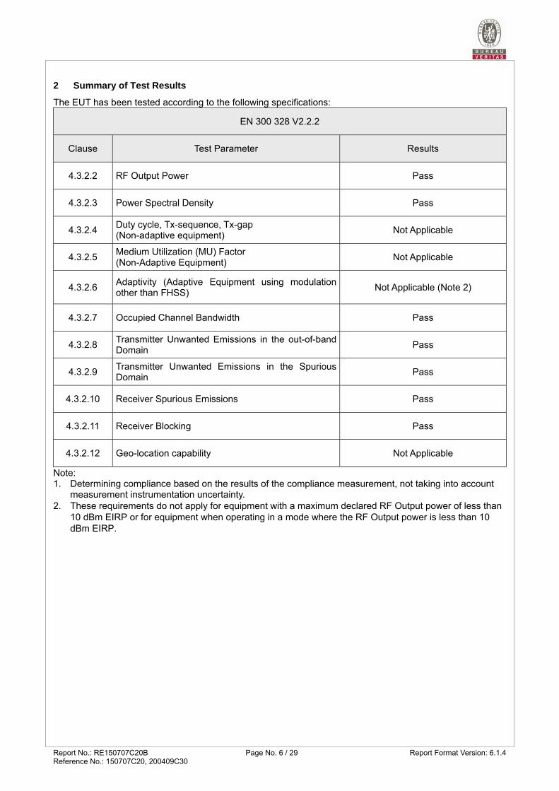
2 Summary of Test Results
The EUT has been tested according to the following specifications:
EN 300 328 V2.2.2
Clause Test Parameter Results
4.3.2.2 RF Output Power Pass
4.3.2.3 Power Spectral Density Pass
4.3.2.4 Duty cycle, Tx-sequence, Tx-gap (Non-adaptive equipment)
Not Applicable
4.3.2.5 Medium Utilization (MU) Factor (Non-Adaptive Equipment)
Not Applicable
4.3.2.6 Adaptivity (Adaptive Equipment using modulation other than FHSS)
Not Applicable (Note 2)
4.3.2.7 Occupied Channel Bandwidth Pass
4.3.2.8 Transmitter Unwanted Emissions in the out-of-band Domain
Pass
4.3.2.9 Transmitter Unwanted Emissions in the Spurious Domain
Pass
4.3.2.10 Receiver Spurious Emissions Pass
4.3.2.11 Receiver Blocking Pass
4.3.2.12 Geo-location capability Not Applicable
Note: 1. Determining compliance based on the results of the compliance measurement, not taking into account
measurement instrumentation uncertainty. 2. These requirements do not apply for equipment with a maximum declared RF Output power of less than
10 dBm EIRP or for equipment when operating in a mode where the RF Output power is less than 10 dBm EIRP.

Report No.: RE150707C20B Page No. 7 / 29 Report Format Version: 6.1.4Reference No.: 150707C20, 200409C30
2.1 Test Instruments
Test Date: Jul. 13 ~ Jul. 14, 2015
Description & Manufacturer Model No. Serial No. Calibrated Date Calibrated UntilSpectrum Analyzer Agilent
E4440A MY46185282 Mar. 09, 2015 Mar. 08, 2016
Spectrum Analyzer Rohde & Schwarz
FSV40 100980 Feb. 10, 2015 Feb. 09, 2016
Signal Generator Agilent
E4438C MY45092849 Dec. 19, 2014 Dec. 18, 2015
Open Switch and Control Unit Rohde & Schwarz
OSP120 B157-100898 Nov. 28, 2014 Nov. 27, 2015
Vector Signal Generator Rohde & Schwarz
SMJ100A 101943 Nov. 21, 2014 Nov. 20, 2015
RF and Microwave Siganl Generator Rohde & Schwarz
SMB100A 177994 Nov. 14, 2014 Nov. 13, 2015
BILOG Antenna SCHWARZBECK
VULB 9168 9168-161 Feb. 04, 2015 Feb. 03, 2016
HORN Antenna ETS
3117 00034130 Feb. 10, 2015 Feb. 09, 2016
HORN Antenna SCHWARZBECK
BBHA 9170 BBHA9170243 Feb. 05, 2015 Feb. 04, 2016
Preamplifier Agilent
8449B 3008A01976 Aug. 22, 2014 Aug. 21, 2015
Preamplifier Agilent
8447D 2944A10634 Aug. 22, 2014 Aug. 21, 2015
RF signal cable HUBER+SUHNER
SUCOFLEX 104 246272/4 Aug. 22, 2014 Aug. 21, 2015
RF signal cable HUBER+SUHNER
SUCOFLEX 104 254644+251640 Aug. 22, 2014 Aug. 21, 2015
RF signal cable HUBER+SUHNER
CA3501-3501-G.90(3m) &
CA3501-3501-F.90(2m)
NF090(3m)*2 & TCF427S(2m)*1
Apr. 07, 2015 Apr. 06, 2016
Software ADT.
ADT_Radiated_ V7.6.15.9.4
NA NA NA
Antenna Tower Max-Full MFA-440H 1308111 NA NA
10dB Attenuation JFW
50HF-010-SMA NA NA NA
Turn Table ADT
NA SN30303 NA NA
Controller Max-Full MF7802 MF780208363 NA NA
Temperature & Humidity chamber TERCHY
MHU-225AU 920842 Jun. 18, 2015 Jun. 17, 2016
Note: 1. The calibration interval of the above test instruments is 12 months and the calibrations are traceable
to NML/ROC and NIST/USA. 2. The test was performed in HwaYa RF Chamber 2. 3. The horn antenna and preamplifier (model: 8449B) are used only for the measurement of emission
frequency above 1GHz if tested.
Report No.: RE150707C20B Page No. 8 / 29 Report Format Version: 6.1.4Reference No.: 150707C20, 200409C30
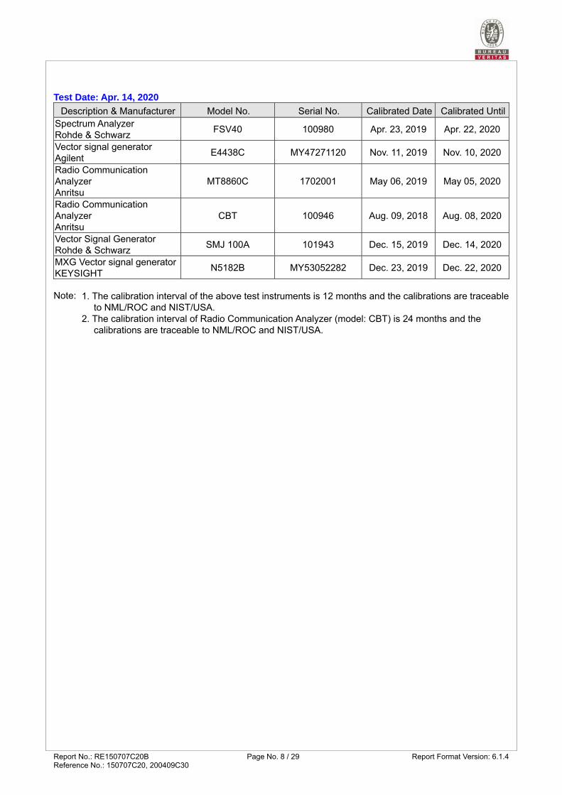
Test Date: Apr. 14, 2020
Description & Manufacturer Model No. Serial No. Calibrated Date Calibrated UntilSpectrum Analyzer Rohde & Schwarz
FSV40 100980 Apr. 23, 2019 Apr. 22, 2020
Vector signal generator Agilent
E4438C MY47271120 Nov. 11, 2019 Nov. 10, 2020
Radio Communication Analyzer Anritsu
MT8860C 1702001 May 06, 2019 May 05, 2020
Radio Communication Analyzer Anritsu
CBT 100946 Aug. 09, 2018 Aug. 08, 2020
Vector Signal Generator Rohde & Schwarz
SMJ 100A 101943 Dec. 15, 2019 Dec. 14, 2020
MXG Vector signal generator KEYSIGHT
N5182B MY53052282 Dec. 23, 2019 Dec. 22, 2020
Note: 1. The calibration interval of the above test instruments is 12 months and the calibrations are traceable
to NML/ROC and NIST/USA. 2. The calibration interval of Radio Communication Analyzer (model: CBT) is 24 months and the
calibrations are traceable to NML/ROC and NIST/USA.

Report No.: RE150707C20B Page No. 9 / 29 Report Format Version: 6.1.4Reference No.: 150707C20, 200409C30
2.2 Measurement Uncertainty
Where relevant, the following measurement uncertainty levels have been estimated for tests performed on the EUT: This uncertainty represents an expanded uncertainty expressed at approximately the 95% confidence level using a coverage factor of k=2.
Parameter Uncertainty
Occupied Channel Bandwidth ±1.229x10⁻⁶ %
RF output power, conducted ±1.371 dB
Power Spectral Density, conducted ±2.889 dB
Unwanted Emissions, conducted ±1.34 dB
All emissions, radiated ±3.013 dB
Temperature ±0.23 °C
Supply voltages ±0.3 %
Time ±2.53 %
2.3 Maximum Measurement Uncertainty
For the test methods, according to ETSI EN 300 328 standard, the measurement uncertainty figures shall be calculated in accordance with ETR 100 028-1 [4] and shall correspond to an expansion factor (coverage factor) k = 1,96 or k = 2 (which provide confidence levels of respectively 95 % and 95,45 % in the case where the distributions characterizing the actual measurement uncertainties are normal (Gaussian)).
Maximum measurement uncertainty Parameter Uncertainty
Occupied Channel Bandwidth ±5 %
RF output power, conducted ±1.5 dB Power Spectral Density, conducted ±3 dB Unwanted Emissions, conducted ±3 dB All emissions, radiated ±6 dB Temperature ±3 °C Supply voltages ±3 % Time ±5 %
2.4 Modification Record
There were no modifications required for compliance.

Report No.: RE150707C20B Page No. 10 / 29 Report Format Version: 6.1.4Reference No.: 150707C20, 200409C30
3 General Information
3.1 General Description of EUT
Product Wireless Module
Brand TAIYO YUDEN
Test Model EYSGJN
Sample Status Engineering sample
Nominal Voltage 3Vdc (Host equipment)
Normal Testing Voltage 3Vdc
Temperature Operating Range -40~85℃
Modulation Type GFSK
Transfer Rate 1Mbps
Operating Frequency 2402MHz~2480MHz
Number of Channel 40
Adaptive/Non-Adaptive
non-adaptive Equipment
adaptive Equipment without the possibility to switch to a non-adaptive
mode
adaptive Equipment which can also operate in a non-adaptive mode
EIRP Power
(Measured Max. Average) 2.77dBm
Antenna Type PCB antenna with -1.5dBi gain
Accessory Device NA
Data Cable Supplied NA
Note:
1. This report is issued as a supplementary report of the original report no.: RE150707C20A. The difference compared with the original design is updating standard from EN 300 328 V2.1.1 to V2.2.2. Therefore, only Receiver Blocking test had been re-tested and the other test data was kept in this report.
2. According to above conditions, the limit of frequency range 470 MHz to 694 MHz: -54 dBm/100 kHz, 694 MHz to 1 GHz: -36 dBm/100 kHz for Transmitter Unwanted Emissions in the Spurious Domain (Below 1GHz) updated is no need test, only Receiver Blocking test item needs to be performed. All data for meeting the requirement is verified.

Report No.: RE150707C20B Page No. 11 / 29 Report Format Version: 6.1.4Reference No.: 150707C20, 200409C30
3.2 Description of Test Modes
40 channels are provided to this EUT:
Channel Freq. (MHz) Channel Freq. (MHz) Channel Freq. (MHz) Channel Freq. (MHz)
0 2402 10 2422 20 2442 30 2462
1 2404 11 2424 21 2444 31 2464
2 2406 12 2426 22 2446 32 2466
3 2408 13 2428 23 2448 33 2468
4 2410 14 2430 24 2450 34 2470
5 2412 15 2432 25 2452 35 2472
6 2414 16 2434 26 2454 36 2474
7 2416 17 2436 27 2456 37 2476
8 2418 18 2438 28 2458 38 2478
9 2420 19 2440 29 2460 39 2480

Report No.: RE150707C20B Page No. 12 / 29 Report Format Version: 6.1.4Reference No.: 150707C20, 200409C30
3.2.1 Test Mode Applicability and Tested Channel Detail
EUT Configure
Mode
Applicable to Description
ROP PSD DC/TS/TG MU AD OCB EOB SE< 1G SE 1G RB
- √ √ - - - √ √ √ √ √ -
Where ROP: RF Output Power PSD: Power Spectral Density
DC/TS/TG: Duty Cycle/ Tx-Sequence / Tx-gap MU: Medium Utilization
AD: Adaptivity (Channel Access Mechanism) OCB: Occupied Channel Bandwidth
EOB: Transmitter unwanted emissions in the out-of-band domain
SE<1G: Unwanted Emissions in the Spurious Domain below 1 GHz
SE1G: Unwanted Emissions in the Spurious Domain above 1 GHz
RB: Receiver Blocking
Note: The EUT had been pre-tested on the positioned of each 3 axis. The worst case was found when positioned on X-plane.
RF Output Power Test:
Pre-Scan has been conducted to determine the worst-case mode from all possible combinations between available modulations, data rates and antenna ports (if EUT with antenna diversity architecture).
Following channel(s) was (were) selected for the final test as listed below. EUT Configure Mode Available Channel Tested Channel Modulation Type Data Rate (Mbps)
- 0 to 39 0, 19, 39 GFSK 1.0
Power Spectral Density Test:
Pre-Scan has been conducted to determine the worst-case mode from all possible combinations between available modulations, data rates and antenna ports (if EUT with antenna diversity architecture).
Following channel(s) was (were) selected for the final test as listed below. EUT Configure Mode Available Channel Tested Channel Modulation Type Data Rate (Mbps)
- 0 to 39 0, 19, 39 GFSK 1.0
Occupied Channel Bandwidth Test:
Pre-Scan has been conducted to determine the worst-case mode from all possible combinations between available modulations, data rates and antenna ports (if EUT with antenna diversity architecture).
Following channel(s) was (were) selected for the final test as listed below. EUT Configure Mode Available Channel Tested Channel Modulation Type Data Rate (Mbps)
- 0 to 39 0, 39 GFSK 1.0

Report No.: RE150707C20B Page No. 13 / 29 Report Format Version: 6.1.4Reference No.: 150707C20, 200409C30
Transmitter Unwanted Emissions in the Out-of-band Domain Test:
Pre-Scan has been conducted to determine the worst-case mode from all possible combinations between available modulations, data rates and antenna ports (if EUT with antenna diversity architecture).
Following channel(s) was (were) selected for the final test as listed below. EUT Configure Mode Available Channel Tested Channel Modulation Type Data Rate (Mbps)
- 0 to 39 0, 39 GFSK 1.0
Unwanted Emissions in the Spurious Domain Test (Below 1 GHz):
Pre-Scan has been conducted to determine the worst-case mode from all possible combinations between available modulations, data rates and antenna ports (if EUT with antenna diversity architecture).
Following channel(s) was (were) selected for the final test as listed below. EUT Configure Mode Available Channel Tested Channel Modulation Type Data Rate (Mbps)
- 0 to 39 0 GFSK 1.0
Unwanted Emissions in the Spurious Domain Test (above 1 GHz):
Pre-Scan has been conducted to determine the worst-case mode from all possible combinations between available modulations, data rates and antenna ports (if EUT with antenna diversity architecture).
Following channel(s) was (were) selected for the final test as listed below. EUT Configure Mode Available Channel Tested Channel Modulation Type Data Rate (Mbps)
- 0 to 39 0, 39 GFSK 1.0
Receiver Blocking test: Pre-Scan has been conducted to determine the worst-case mode from all possible combinations
between available modulations, data rates and antenna ports (if EUT with antenna diversity architecture).
Following channel(s) was (were) selected for the final test as listed below. EUT Configure Mode Available Channel Tested Channel Modulation Type Data Rate
- 0 to 39 0, 39 GFSK 1.0
Test Condition:
Applicable To Environmental Conditions Input Power Tested by
ROP 25 deg. C, 60% RH 3Vdc Leo Tsai
PSD 25 deg. C, 60% RH 3Vdc Leo Tsai
OCB 25 deg. C, 60% RH 3Vdc Leo Tsai
EOB 25 deg. C, 60% RH 3Vdc Leo Tsai
SE<1G 25 deg. C, 65% RH 3Vdc Koven Chuang
SE1G 25 deg. C, 65% RH 3Vdc Koven Chuang
RB 25deg. C, 60%RH 3Vdc Vincent Huang
Report No.: RE150707C20B Page No. 14 / 29 Report Format Version: 6.1.4Reference No.: 150707C20, 200409C30
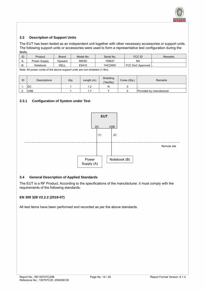
3.3 Description of Support Units
The EUT has been tested as an independent unit together with other necessary accessories or support units. The following support units or accessories were used to form a representative test configuration during the tests.
ID Product Brand Model No. Serial No. FCC ID Remarks
A. Power Supply Topward 6603D 700637 NA -
B. Notebook DELL E5410 1HC2XM1 FCC DoC Approved -
Note: All power cords of the above support units are non-shielded (1.8m).
ID Descriptions Qty. Length (m)Shielding
(Yes/No) Cores (Qty.) Remarks
1. DC 1 1.2 N 0 -
2. USB 1 1.7 Y 0 Provided by manufacturer
3.3.1 Configuration of System under Test
3.4 General Description of Applied Standards
The EUT is a RF Product. According to the specifications of the manufacturer, it must comply with the requirements of the following standards:
EN 300 328 V2.2.2 (2019-07)
All test items have been performed and recorded as per the above standards.
EUT
Power Supply (A)
Remote site
DC
(1)
Notebook (B)
USB
(2)

Report No.: RE150707C20B Page No. 15 / 29 Report Format Version: 6.1.4Reference No.: 150707C20, 200409C30
4 Test Procedure and Results
4.1 RF Output Power
4.1.1 Limits of RF Output Power
Condition Frequency Band Limit (e.i.r.p)
Under all test conditions 2400 ~ 2483.5 MHz AV: 20dBm
4.1.2 Test Procedures
Refer to chapter 5.4.2 of EN 300 328 V2.2.2.
Measurement Method
Conducted measurement Radiated measurement
4.1.3 Deviation from Test Standard
No deviation.
4.1.4 Test Setup
The measurements for RF output power was performed at both normal environmental conditions and at the extremes of the operating temperature. Controlling software (provided by manufacturer) has been activated to set the EUT on specific channel and power level.
4.1.5 Test Results
Test Condition EIRP Power (dBm)
(CH0) 2402 MHz
(CH19) 2440 MHz
(CH39) 2480 MHz
Tnom(℃) +25 Vnom(v) 2.28 2.22 1.78
Tmin(℃) -40 Vnom(v) 2.71 2.77 2.41
Tmax(℃) +85 Vnom(v) 1.53 1.43 0.87
Report No.: RE150707C20B Page No. 16 / 29 Report Format Version: 6.1.4Reference No.: 150707C20, 200409C30
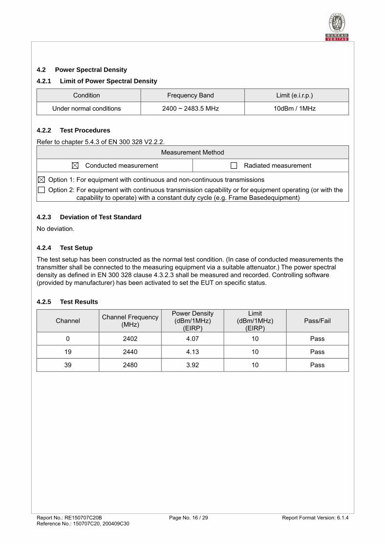
4.2 Power Spectral Density
4.2.1 Limit of Power Spectral Density
Condition Frequency Band Limit (e.i.r.p.)
Under normal conditions 2400 ~ 2483.5 MHz 10dBm / 1MHz
4.2.2 Test Procedures
Refer to chapter 5.4.3 of EN 300 328 V2.2.2.
Measurement Method
Conducted measurement Radiated measurement
Option 1: For equipment with continuous and non-continuous transmissions
Option 2: For equipment with continuous transmission capability or for equipment operating (or with the capability to operate) with a constant duty cycle (e.g. Frame Basedequipment)
4.2.3 Deviation of Test Standard
No deviation.
4.2.4 Test Setup
The test setup has been constructed as the normal test condition. (In case of conducted measurements the transmitter shall be connected to the measuring equipment via a suitable attenuator.) The power spectral density as defined in EN 300 328 clause 4.3.2.3 shall be measured and recorded. Controlling software (provided by manufacturer) has been activated to set the EUT on specific status.
4.2.5 Test Results
Channel Channel Frequency
(MHz)
Power Density (dBm/1MHz)
(EIRP)
Limit (dBm/1MHz)
(EIRP) Pass/Fail
0 2402 4.07 10 Pass
19 2440 4.13 10 Pass
39 2480 3.92 10 Pass

Report No.: RE150707C20B Page No. 17 / 29 Report Format Version: 6.1.4Reference No.: 150707C20, 200409C30
4.3 Occupied Channel Bandwidth
4.3.1 Limit of Occupied Channel Bandwidth
Condition Limit
All types of equipment Shall fall completely within the band
2400 to 2483.5 MHz.
Additional requirement
For non-adaptive using wide band modulations other than FHSS system and
e.i.r.p >10dBm. Less than 20MHz
For non-adaptive Frequency Hopping system and e.i.r.p >10dBm.
Less than 5MHz
4.3.2 Test Procedure
Refer to chapter 5.4.7 of EN 300 328 V2.2.2.
Measurement Method
Conducted measurement Radiated measurement
4.3.3 Deviation from Test Standard
No deviation.
4.3.4 Test Setup
These measurements only were performed at normal test conditions. The measurement shall be performed only on the lowest and the highest frequency within the stated frequency range. In case of conducted measurements the transmitter shall be connected to the measuring equipment via a suitable attenuator. Controlling software (provided by manufacturer) has been activated to set the EUT on specific status.
4.3.5 Test Results
Channel Channel
Frequency (MHz)
Occupied Bandwidth
(MHz)
Measured Frequencies Limit Pass/Fail
FL (MHz) FH (MHz)
0 2402 2.40 2400.80 2403.20 FL > 2400 MHz and
FH < 2483.5 MHz
Pass
39 2480 2.40 2478.80 2481.20 Pass
Note: FL is the lowest frequency of the 99% occupied bandwidth of power envelope. FH is the highest frequency of the 99% occupied bandwidth of power envelope.

Report No.: RE150707C20B Page No. 18 / 29 Report Format Version: 6.1.4Reference No.: 150707C20, 200409C30
4.4 Transmitter Unwanted Emissions in the Out-of-band Domain
4.4.1 Limits of Transmitter Unwanted Emissions in the Out-of-band Domain
4.4.2 Test Procedure
Refer to chapter 5.4.8 of EN 300 328 V2.2.2.
Measurement Method
Conducted measurement Radiated measurement
4.4.3 Deviation from Test Standard
No deviation
4.4.4 Test Setup
The measurements were performed at normal environmental conditions and shall be repeated at the extremes of the operating temperature. The measurement was performed at the lowest and the highest channel on which the equipment can operate. The equipment was configured to operate under its worst case situation with respect to output power. In case of conducted measurements the transmitter shall be connected to the measuring equipment via a suitable attenuator. The frequency has to be recorded for the right and left end above threshold of highest and lowest channel respectively.
Condition Limit
Under all test conditions The transmitter unwanted emissions in the out-of-band domain but outside the allocated band, shall not exceed the values provided by the mask in below figure.

Report No.: RE150707C20B Page No. 19 / 29 Report Format Version: 6.1.4Reference No.: 150707C20, 200409C30
4.4.5 Test Results
Channel Frequency 2402MHz 2480MHz
Test Condition
OOB Emission (MHz) OOB Emission (MHz)
2397.6 ~ 2400 2395.2 ~ 2397.6 2483.5 ~ 2485.9 2485.9 ~ 2488.3
Freq. (MHz)
Power (dBm/ MHz)
Freq. (MHz)
Power (dBm/ MHz)
Freq. (MHz)
Power (dBm/ MHz)
Freq. (MHz)
Power (dBm/ MHz)
Tnom 25℃ Vnom(v) 2399.50 -36.85 2396.10 -45.89 2485.00 -37.75 2486.40 -50.08
Tmin -40℃ Vnom(v) 2399.50 -37.01 2396.10 -45.69 2485.00 -37.68 2486.40 -50.27
Tmax 85℃ Vnom(v) 2399.50 -36.82 2396.10 -46.05 2485.00 -37.91 2486.40 -49.96
Limit (dBm/MHz) -10.00 -20.00 -10.00 -20.00
Pass/Fail Pass Pass Pass Pass
Report No.: RE150707C20B Page No. 20 / 29 Report Format Version: 6.1.4Reference No.: 150707C20, 200409C30
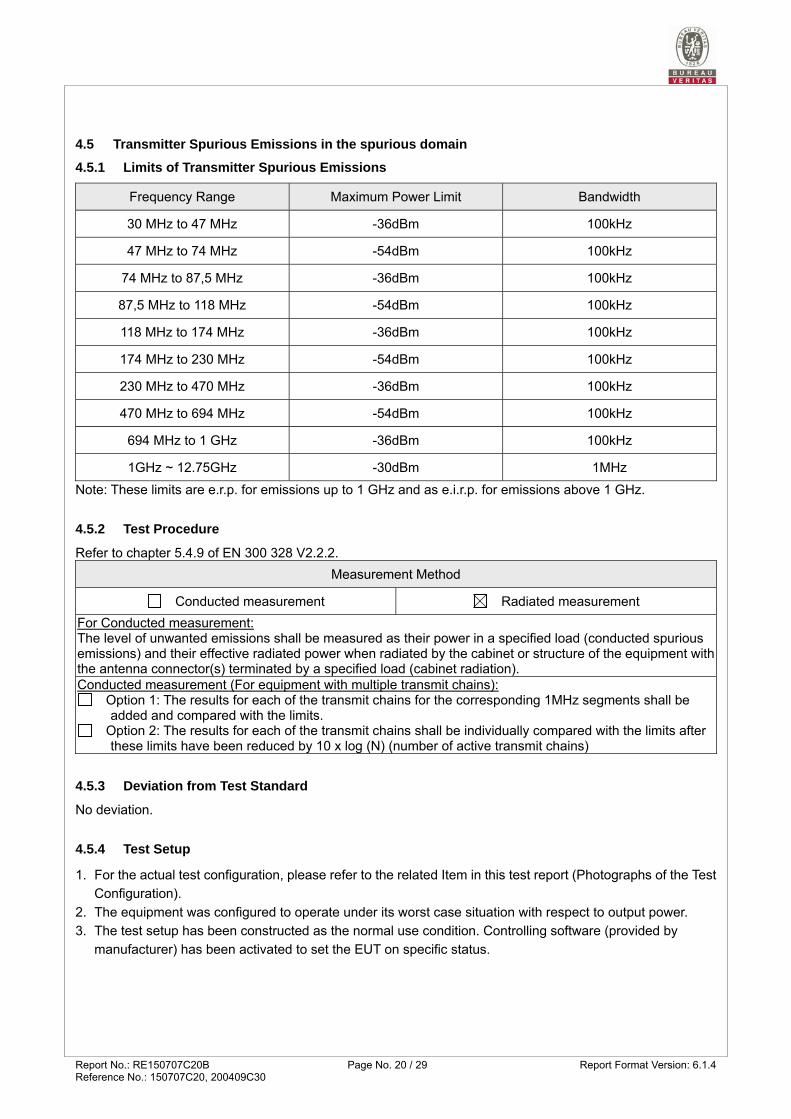
4.5 Transmitter Spurious Emissions in the spurious domain
4.5.1 Limits of Transmitter Spurious Emissions
Frequency Range Maximum Power Limit Bandwidth
30 MHz to 47 MHz -36dBm 100kHz
47 MHz to 74 MHz -54dBm 100kHz
74 MHz to 87,5 MHz -36dBm 100kHz
87,5 MHz to 118 MHz -54dBm 100kHz
118 MHz to 174 MHz -36dBm 100kHz
174 MHz to 230 MHz -54dBm 100kHz
230 MHz to 470 MHz -36dBm 100kHz
470 MHz to 694 MHz -54dBm 100kHz
694 MHz to 1 GHz -36dBm 100kHz
1GHz ~ 12.75GHz -30dBm 1MHz
Note: These limits are e.r.p. for emissions up to 1 GHz and as e.i.r.p. for emissions above 1 GHz.
4.5.2 Test Procedure
Refer to chapter 5.4.9 of EN 300 328 V2.2.2.
Measurement Method
Conducted measurement Radiated measurement
For Conducted measurement: The level of unwanted emissions shall be measured as their power in a specified load (conducted spurious emissions) and their effective radiated power when radiated by the cabinet or structure of the equipment withthe antenna connector(s) terminated by a specified load (cabinet radiation). Conducted measurement (For equipment with multiple transmit chains):
Option 1: The results for each of the transmit chains for the corresponding 1MHz segments shall be added and compared with the limits.
Option 2: The results for each of the transmit chains shall be individually compared with the limits after these limits have been reduced by 10 x log (N) (number of active transmit chains)
4.5.3 Deviation from Test Standard
No deviation.
4.5.4 Test Setup
1. For the actual test configuration, please refer to the related Item in this test report (Photographs of the Test
Configuration).
2. The equipment was configured to operate under its worst case situation with respect to output power.
3. The test setup has been constructed as the normal use condition. Controlling software (provided by
manufacturer) has been activated to set the EUT on specific status.

Report No.: RE150707C20B Page No. 21 / 29 Report Format Version: 6.1.4Reference No.: 150707C20, 200409C30
4.5.5 Test Results
Worst-case Data:
Frequency Range 30MHz ~ 1GHz Operating Channel 0
Spurious Emission Level
Frequency (MHz)
Antenna Polarization
Level (dBm)
Limit (dBm)
Margin (dB)
48.00 V -68.25 -54.00 -14.25
90.68 V -63.01 -54.00 -9.01
99.87 H -62.68 -54.00 -8.68
182.26 V -62.95 -54.00 -8.95
209.17 H -70.51 -54.00 -16.51
479.53 H -62.22 -54.00 -8.22
479.98 V -62.31 -54.00 -8.31
576.05 H -62.49 -54.00 -8.49
576.80 V -63.12 -54.00 -9.12
599.71 V -61.30 -54.00 -7.30
766.94 H -62.20 -54.00 -8.20
768.40 V -63.11 -54.00 -9.11
827.34 H -62.12 -54.00 -8.12
Frequency Range 1GHz ~ 12.75GHz Operating Channel 0, 39
Spurious Emission Level
Channel Frequency
(MHz) Antenna
Polarization Level (dBm)
Limit (dBm)
Margin (dB)
0
4804.40 V -56.06 -30.00 -26.06
4805.89 H -56.22 -30.00 -26.22
9606.80 H -49.70 -30.00 -19.70
9608.70 V -49.54 -30.00 -19.54
39
4959.48 H -56.01 -30.00 -26.01
4960.06 V -54.57 -30.00 -24.57
9919.68 H -49.23 -30.00 -19.23
9919.96 V -49.25 -30.00 -19.25

Report No.: RE150707C20B Page No. 22 / 29 Report Format Version: 6.1.4Reference No.: 150707C20, 200409C30
4.6 Receiver Spurious Emissions
4.6.1 Limit of Receiver Spurious Emissions
Frequency Range Maximum Power Limit Bandwidth
30 MHz ~ 1 GHz -57dBm 100 kHz
1 GHz ~ 12.75 GHz -47dBm 1 MHz
Note: These limits are e.r.p. for emissions up to 1 GHz and as e.i.r.p. for emissions above 1 GHz.
4.6.2 Test Procedure
Refer to chapter 5.4.10 of EN 300 328 V2.2.2.
Measurement Method
Conducted measurement Radiated measurement
For Conducted measurement: The level of unwanted emissions shall be measured as their power in a specified load (conducted spurious emissions) and their effective radiated power when radiated by the cabinet or structure of the equipment withthe antenna connector(s) terminated by a specified load (cabinet radiation). Conducted measurement (For equipment with multiple transmit chains):
Option 1: The results for each of the transmit chains for the corresponding 1MHz segments shall be added and compared with the limits.
Option 2: The results for each of the transmit chains shall be individually compared with the limits after these limits have been reduced by 10 x log (N) (number of active transmit chains)
4.6.3 Deviation from Test Standard
No deviation.
4.6.4 Test Setup
1. For the actual test configuration, please refer to the related Item in this test report (Photographs of the
Test Configuration).
2. Testing was performed when the equipment was in a receive-only mode.
3. The test setup has been constructed as the normal use condition. Controlling software (provided by
manufacturer) has been activated to set the EUT on specific status.
Report No.: RE150707C20B Page No. 23 / 29 Report Format Version: 6.1.4Reference No.: 150707C20, 200409C30
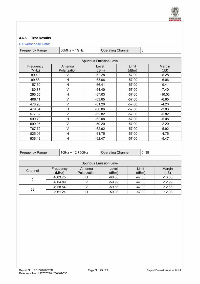
4.6.5 Test Results
RX worst-case Data:
Frequency Range 30MHz ~ 1GHz Operating Channel 0
Spurious Emission Level
Frequency (MHz)
Antenna Polarization
Level (dBm)
Limit (dBm)
Margin (dB)
89.40 V -62.28 -57.00 -5.28
99.88 H -63.06 -57.00 -6.06
157.50 H -66.41 -57.00 -9.41
180.87 V -64.40 -57.00 -7.40
265.55 H -67.03 -57.00 -10.03
408.11 V -63.65 -57.00 -6.65
478.95 V -61.20 -57.00 -4.20
479.64 H -60.86 -57.00 -3.86
577.32 V -62.82 -57.00 -5.82
599.79 H -62.08 -57.00 -5.08
599.96 V -59.20 -57.00 -2.20
767.72 V -62.92 -57.00 -5.92
825.06 H -61.75 -57.00 -4.75
936.42 H -62.47 -57.00 -5.47
Frequency Range 1GHz ~ 12.75GHz Operating Channel 0, 39
Spurious Emission Level
Channel Frequency
(MHz) Antenna
Polarization Level (dBm)
Limit (dBm)
Margin (dB)
0 4803.75 H -60.55 -47.00 -13.55
4804.89 V -59.99 -47.00 -12.99
39 4958.54 V -59.56 -47.00 -12.56
4961.24 H -59.98 -47.00 -12.98
Report No.: RE150707C20B Page No. 24 / 29 Report Format Version: 6.1.4Reference No.: 150707C20, 200409C30
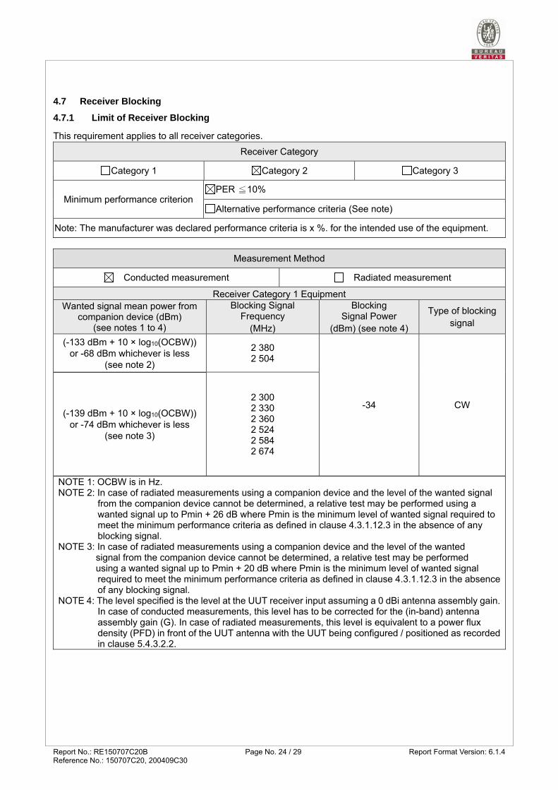
4.7 Receiver Blocking
4.7.1 Limit of Receiver Blocking
This requirement applies to all receiver categories.
Receiver Category
Category 1 Category 2 Category 3
Minimum performance criterion PER ≦10%
Alternative performance criteria (See note)
Note: The manufacturer was declared performance criteria is x %. for the intended use of the equipment.
Measurement Method
Conducted measurement Radiated measurement
Receiver Category 1 Equipment Wanted signal mean power from
companion device (dBm) (see notes 1 to 4)
Blocking Signal Frequency
(MHz)
Blocking Signal Power
(dBm) (see note 4)
Type of blocking signal
(-133 dBm + 10 × log10(OCBW)) or -68 dBm whichever is less
(see note 2)
2 380 2 504
-34 CW (-139 dBm + 10 × log10(OCBW))
or -74 dBm whichever is less (see note 3)
2 300 2 330 2 360 2 524 2 584 2 674
NOTE 1: OCBW is in Hz. NOTE 2: In case of radiated measurements using a companion device and the level of the wanted signal
from the companion device cannot be determined, a relative test may be performed using a wanted signal up to Pmin + 26 dB where Pmin is the minimum level of wanted signal required to meet the minimum performance criteria as defined in clause 4.3.1.12.3 in the absence of any blocking signal.
NOTE 3: In case of radiated measurements using a companion device and the level of the wanted signal from the companion device cannot be determined, a relative test may be performed using a wanted signal up to Pmin + 20 dB where Pmin is the minimum level of wanted signal required to meet the minimum performance criteria as defined in clause 4.3.1.12.3 in the absence of any blocking signal.
NOTE 4: The level specified is the level at the UUT receiver input assuming a 0 dBi antenna assembly gain. In case of conducted measurements, this level has to be corrected for the (in-band) antenna assembly gain (G). In case of radiated measurements, this level is equivalent to a power flux density (PFD) in front of the UUT antenna with the UUT being configured / positioned as recorded in clause 5.4.3.2.2.

Report No.: RE150707C20B Page No. 25 / 29 Report Format Version: 6.1.4Reference No.: 150707C20, 200409C30
Receiver Category 2 Equipment Wanted signal mean power from
companion device (dBm) (see notes 1 to 3)
Blocking Signal Frequency
(MHz)
Blocking Signal Power
(dBm) (see note 3)
Type of blocking signal
(-139 dBm + 10 × log10(OCBW) +10) or (-74 dBm + 10) whichever is less
(see note 2)
2 380 2 504 2 300 2 584
-34 CW
NOTE 1: OCBW is in Hz. NOTE 2: In case of radiated measurements using a companion device and the level of the wanted signal
from the companion device cannot be determined, a relative test may be performed using a wanted signal up to Pmin + 26 dB where Pmin is the minimum level of wanted signal required to meet the minimum performance criteria as defined in clause 4.3.1.12.3 in the absence of any blocking signal.
NOTE 3: The level specified is the level at the UUT receiver input assuming a 0 dBi antenna assembly gain. In case of conducted measurements, this level has to be corrected for the (in-band) antenna assembly gain (G). In case of radiated measurements, this level is equivalent to a power flux density (PFD) in front of the UUT antenna with the UUT being configured / positioned as recorded in clause 5.4.3.2.2.
Receiver Category 3 Equipment
Wanted signal mean power from companion device (dBm)
(see notes 1 to 3)
Blocking Signal Frequency
(MHz)
Blocking Signal Power
(dBm) (See note 3)
Type of blocking signal
(-139 dBm + 10 × log10(OCBW) +20) or (-74 dBm + 20) whichever is less
(see note 2)
2 380 2 504 2 300 2 584
-34 CW
NOTE 1: OCBW is in Hz. NOTE 2: In case of radiated measurements using a companion device and the level of the wanted signal
from the companion device cannot be determined, a relative test may be performed using a wanted signal up to Pmin + 26 dB where Pmin is the minimum level of wanted signal required to meet the minimum performance criteria as defined in clause 4.3.1.12.3 in the absence of any blocking signal.
NOTE 3: The level specified is the level at the UUT receiver input assuming a 0 dBi antenna assembly gain. In case of conducted measurements, this level has to be corrected for the (in-band) antenna assembly gain (G). In case of radiated measurements, this level is equivalent to a power flux density (PFD) in front of the UUT antenna with the UUT being configured / positioned as recorded in clause 5.4.3.2.2.
4.7.2 Test Procedure
Refer to chapter 5.4.11 of EN 300 328 V2.2.2.
Measurement Method
Conducted measurement Radiated measurement
4.7.3 Deviation from Test Standard
No deviation.

Report No.: RE150707C20B Page No. 26 / 29 Report Format Version: 6.1.4Reference No.: 150707C20, 200409C30
4.7.4 Test Setup Configuration
4.7.5 Test Results
Receiver blocking performance when operating at the lowest and highest channels
CH 0 OCBW 2.4 MHzAntenna Gain: -1.5 dBi
Blocking signal Power
at the antenna connector
CH 39 OCBW 2.4 MHz in front of the antenna
Operation Mode
Channel Number
Wanted signal mean power from companion
device (dBm) (Note 1)
Blocking signal
frequency (MHz)
Blocking signal frequency shift
(MHz) (Note 2)
Blocking signal power
(dBm) (Note 1)
Pass/Fail
BT LE
0 -66.7 2380 - -35.5 Pass
-66.7 2300 - -35.5 Pass
39 -66.7 2504 - -35.5 Pass
-66.7 2584 - -35.5 Pass
Note 1: In case of conducted measurements, this level has to be corrected for the (in-band) antenna assembly gain (G).
Note 2: If the performance criteria is not met, those frequencies of the blocking signal has been increased/decreased with a value equal to the Occupied Channel Bandwidth except the blocking frequencies 2380, 2504MHz shall be increased/decreased with a value equal to 10MHz also if the frequency offset is more than 7MHz, the level of the wanted signal shall be increased by 3dB.

Report No.: RE150707C20B Page No. 27 / 29 Report Format Version: 6.1.4Reference No.: 150707C20, 200409C30
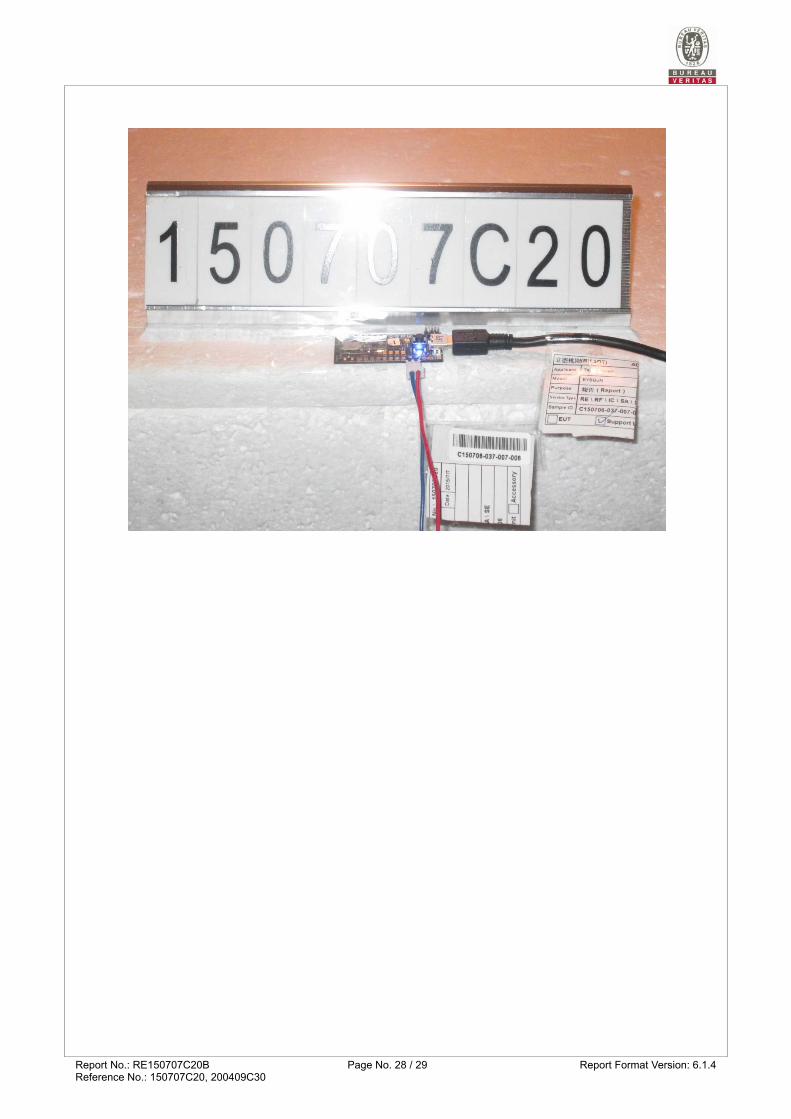
5 Photographs of the Test Configuration
TX / RX Spurious Emission Test
Report No.: RE150707C20B Page No. 28 / 29 Report Format Version: 6.1.4Reference No.: 150707C20, 200409C30

Report No.: RE150707C20B Page No. 29 / 29 Report Format Version: 6.1.4Reference No.: 150707C20, 200409C30
Appendix – Information of the Testing Laboratories We, Bureau Veritas Consumer Products Services (H.K.) Ltd., Taoyuan Branch, were founded in 1988 to provide our best service in EMC, Radio, Telecom and Safety consultation. Our laboratories are FCC recognized accredited test firms and accredited and approved according to ISO/IEC 17025. If you have any comments, please feel free to contact us at the following:
Lin Kou EMC/RF Lab
Tel: 886-2-26052180
Fax: 886-2-26051924
Hsin Chu EMC/RF/Telecom Lab
Tel: 886-3-6668565
Fax: 886-3-6668323
Hwa Ya EMC/RF/Safety Lab
Tel: 886-3-3183232
Fax: 886-3-3270892
Email: [email protected]
Web Site: www.bureauveritas-adt.com
The address and road map of all our labs can be found in our web site also. --- END ---