
EMC standards
141
EMC standards ITU Training on Conformance and Interoperability for AFR Region CERT, 28 October – 1 st November 2013, 1 [email protected] [email protected]
-
Upload
nguyenthuan -
Category
Documents
-
view
217 -
download
0
Transcript of EMC standards

EMC standards
ITU Training on Conformance and Interoperability
for AFR Region
CERT, 28 October – 1st November 2013,
1
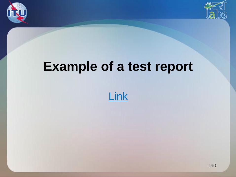
Types of EMC measures
Immunity Emission
Radiated
Conducted

Immunity tests
The purpose of immunity tests is to
subject a product to a controlled stress
that represents the likely range which is
mostly dedicated by practical aspects
and experience of real-world problems.
3

Immunity tests
1 – transient phenomena
4

5
Performance Criteria
for Immunity Tests
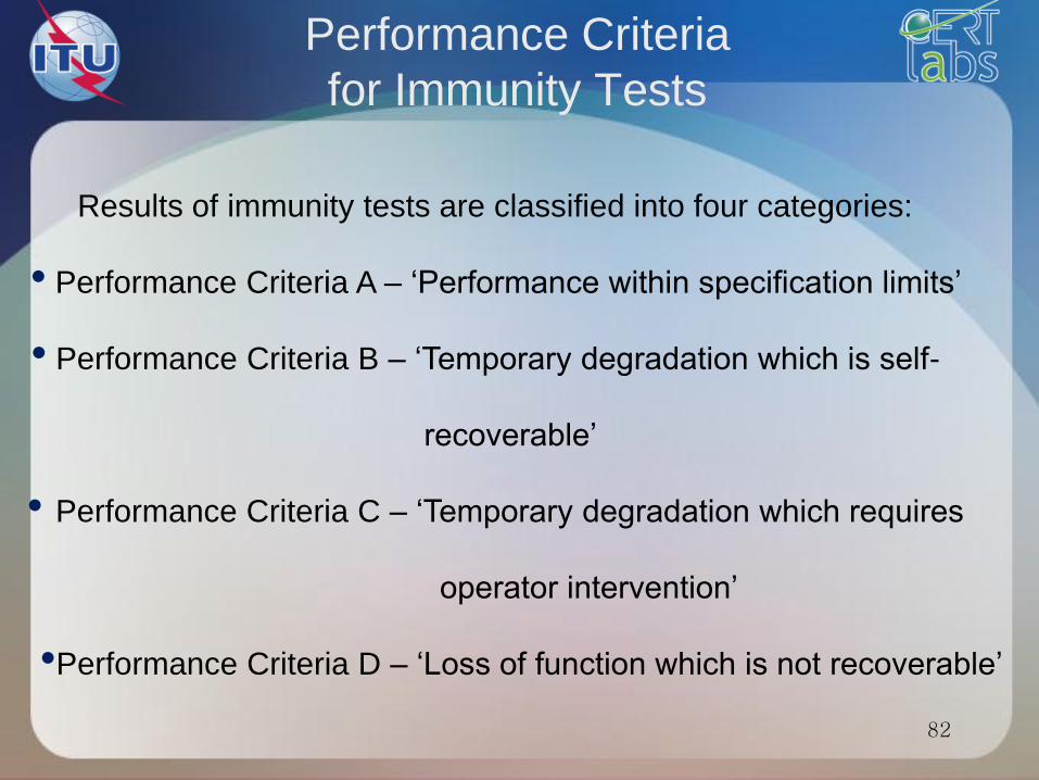
Results of immunity tests are classified into four categories:
• Performance Criteria A – ‘Performance within specification limits’
• Performance Criteria B – ‘Temporary degradation which is self-
recoverable’
• Performance Criteria C – ‘Temporary degradation which requires
operator intervention’
•Performance Criteria D – ‘Loss of function which is not recoverable’
ESD
IEC 61000-4-2
6

Electrostatic Discharge ESD – IEC 61000-4-2
7
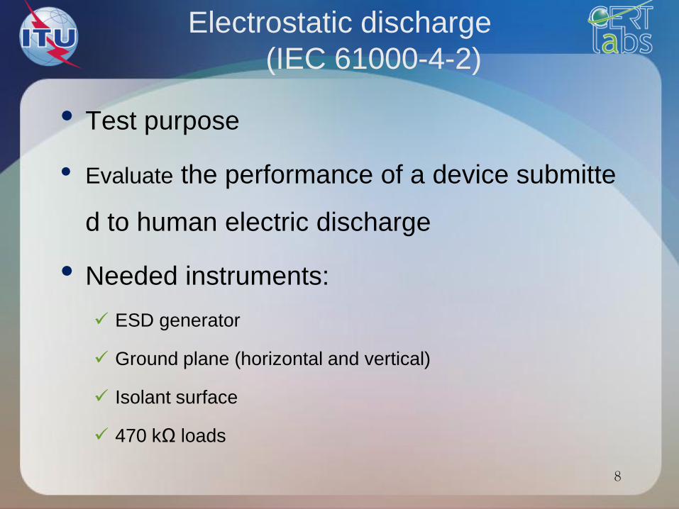
Electrostatic discharge
(IEC 61000-4-2)
8
• Test purpose
• Evaluate the performance of a device submitte
d to human electric discharge
• Needed instruments:
ESD generator
Ground plane (horizontal and vertical)
Isolant surface
470 kΩ loads

9
ESD generator

ESD Test setup
EUT
470 kOhm
470 kOhm
0.1 m
VCP
470 kOhm
470 kOhm
Conducting
surface
Dielectrical
material
Isolating
surface

11
ESD Waveform

12
Test levels

13
Performance Criteria
for Immunity Tests
Results of immunity tests are classified into four categories:
• Performance Criteria A – ‘Performance within specification limits’
• Performance Criteria B – ‘Temporary degradation which is self-
recoverable’
• Performance Criteria C – ‘Temporary degradation which requires
operator intervention’
•Performance Criteria D – ‘Loss of function which is not recoverable’

Standards calls
14
15
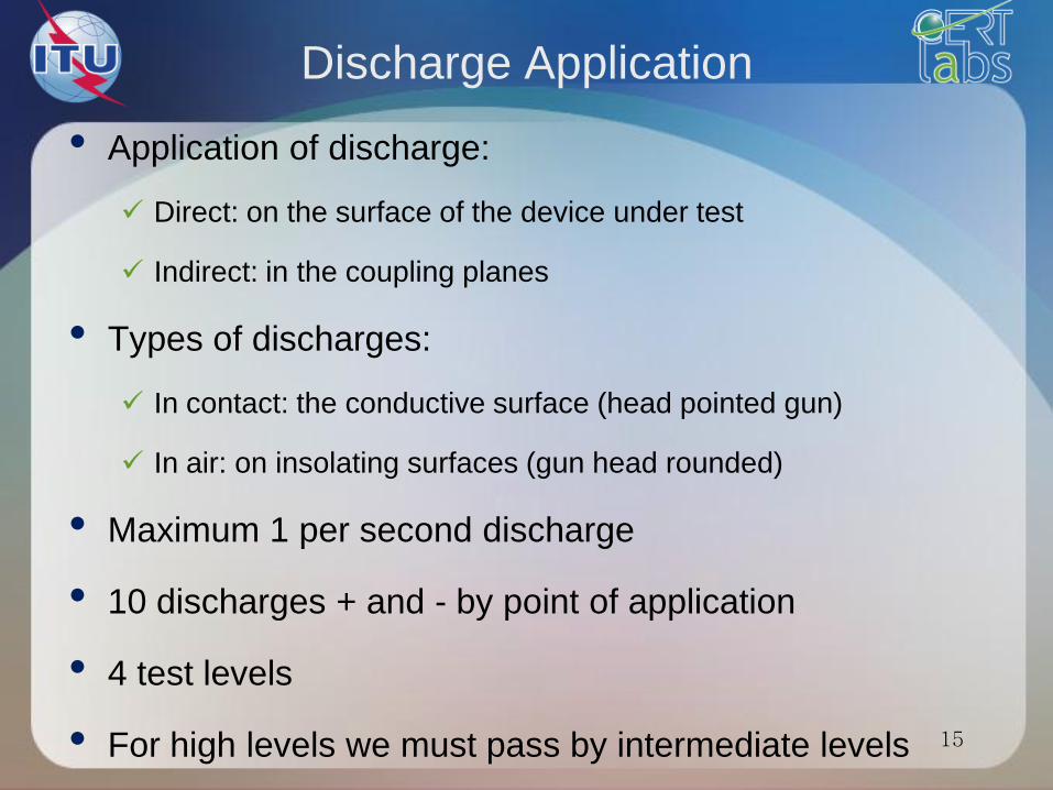
Discharge Application
• Application of discharge:
Direct: on the surface of the device under test
Indirect: in the coupling planes
• Types of discharges:
In contact: the conductive surface (head pointed gun)
In air: on insolating surfaces (gun head rounded)
• Maximum 1 per second discharge
• 10 discharges + and - by point of application
• 4 test levels
• For high levels we must pass by intermediate levels

16
Choice of discharge points

17
• The discharge return cable of the ESD
generator shall be connected to the ground
reference plane. The total length of this cable
is in general 2 m.
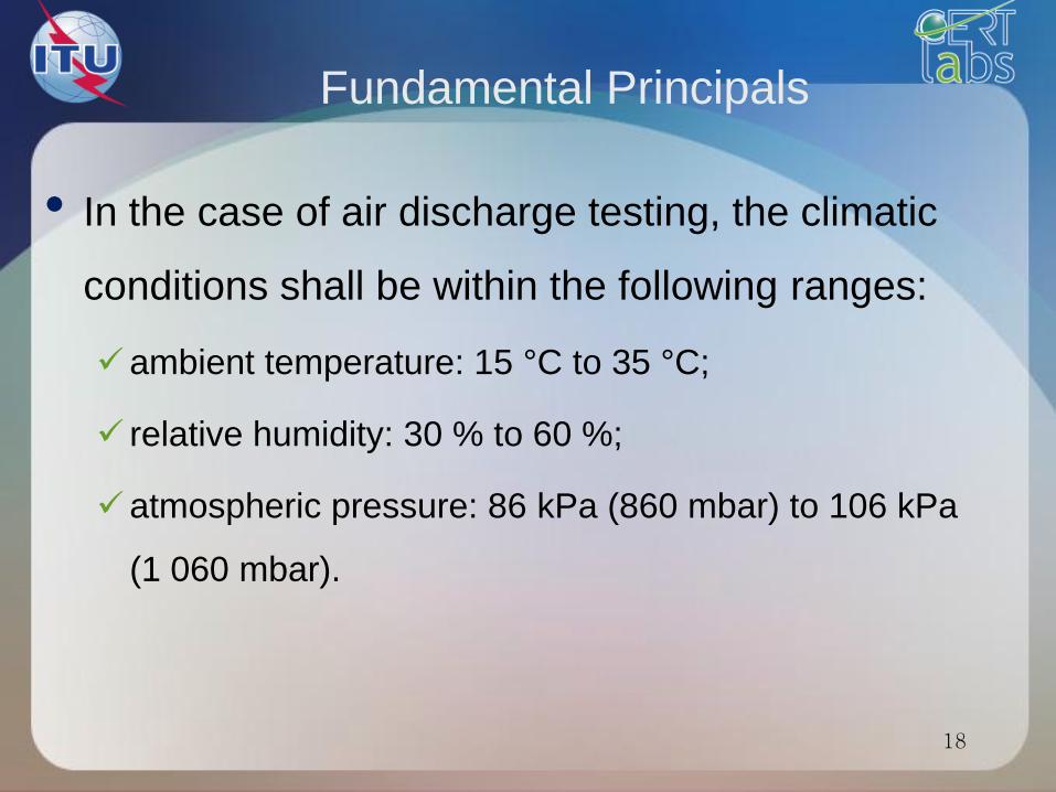
Fundamental Principals
18
• In the case of air discharge testing, the climatic
conditions shall be within the following ranges:
ambient temperature: 15 °C to 35 °C;
relative humidity: 30 % to 60 %;
atmospheric pressure: 86 kPa (860 mbar) to 106 kPa
(1 060 mbar).

19
The testing shall be performed by direct and indirect application
of discharges to the EUT according to a test plan. This should
include:
representative operating conditions of the EUT;
whether the EUT should be tested as table-top or floor-standing;
the points at which discharges are to be applied;
at each point, whether contact or air discharges are to be applied;
the test level to be applied;
the number of discharges to be applied at each point for complia
nce testing;
whether post-installation tests are also to be applied.
Execution of the test

20 • Link to the standard IEC 61000-4-2
• In the case of contact discharges, the tip of the d
ischarge electrode shall touch the EUT, before th
e discharge switch is operated.
• In the case of air discharges, the round discharg
e tip of the discharge electrode shall be approac
hed as fast as possible (without causing mechan
ical damage) to touch the EUT.
Contact/air discharge
ESD design
Design to avoid ESD problems includes:
• choose circuit configurations that are unresponsive to short
transients
• lay out the PCB to minimise induced voltages at critical
nodes
• prevent unavoidable discharge transients from coupling
into circuits and cables
• design enclosures as far as possible to prevent discharges
from occurring
21

EFT
IEC 61000-4-4
22
The EFT phenomenum
• When a circuit is switched off, the current fl owing through
the switch is interrupted more or less instantaneously.
• At the moment of switching there is an infinite di/dt.
• All circuits have some stray inductance associated with
the wiring; some types of load, such as motors or
solenoids, have considerably more inductance in the load
itself.
• The voltage developed across an inductance L by a
changing current i is :
V = -L ∙ di/dt
23
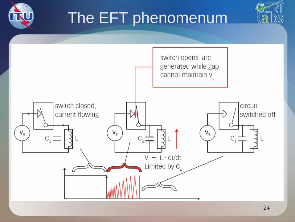
The EFT phenomenum
24
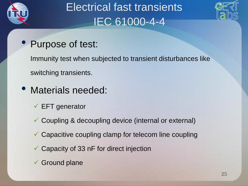
Electrical fast transients
IEC 61000-4-4
25
• Purpose of test:
Immunity test when subjected to transient disturbances like
switching transients.
• Materials needed:
EFT generator
Coupling & decoupling device (internal or external)
Capacitive coupling clamp for telecom line coupling
Capacity of 33 nF for direct injection
Ground plane

26
Electric Fast Transients
EFT – Burst – EN 61000-4-4
EUT
Burst generator
With integrated CDN
Wave form generator Coupling/decoupling
Network
Ground plane
0.1 m Dielectric material 0.1 m

27
Test levels

28
Performance Criteria
for Immunity Tests
Results of immunity tests are classified into four categories:
• Performance Criteria A – ‘Performance within specification limits’
• Performance Criteria B – ‘Temporary degradation which is self-
recoverable’
• Performance Criteria C – ‘Temporary degradation which requires
operator intervention’
•Performance Criteria D – ‘Loss of function which is not recoverable’
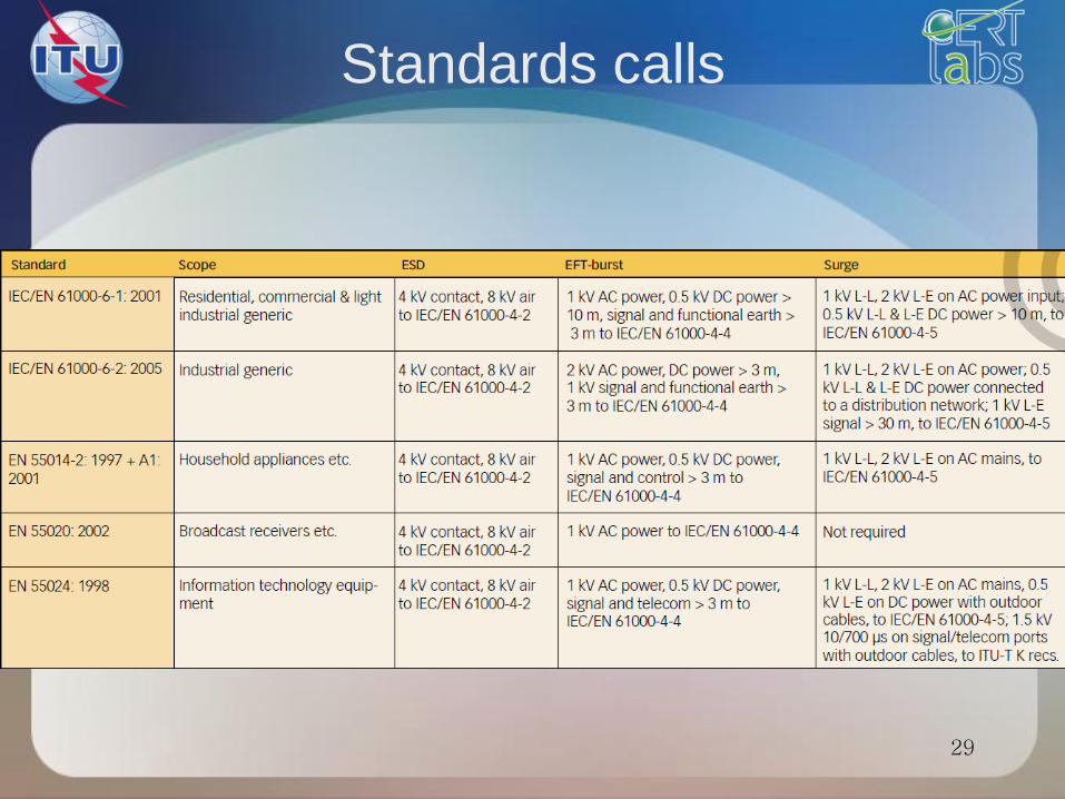
Standards calls
29
30
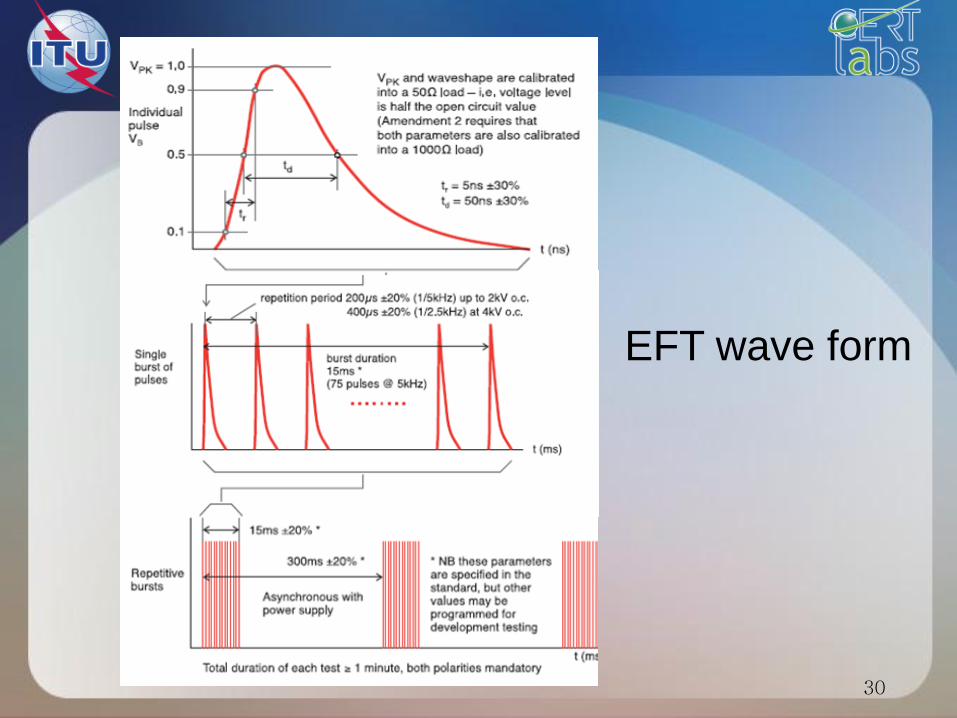
EFT wave form
31
• On each conductor
• For at least 1 min
• polarity + And –
• Test levels and intermediate levels
EFT Application
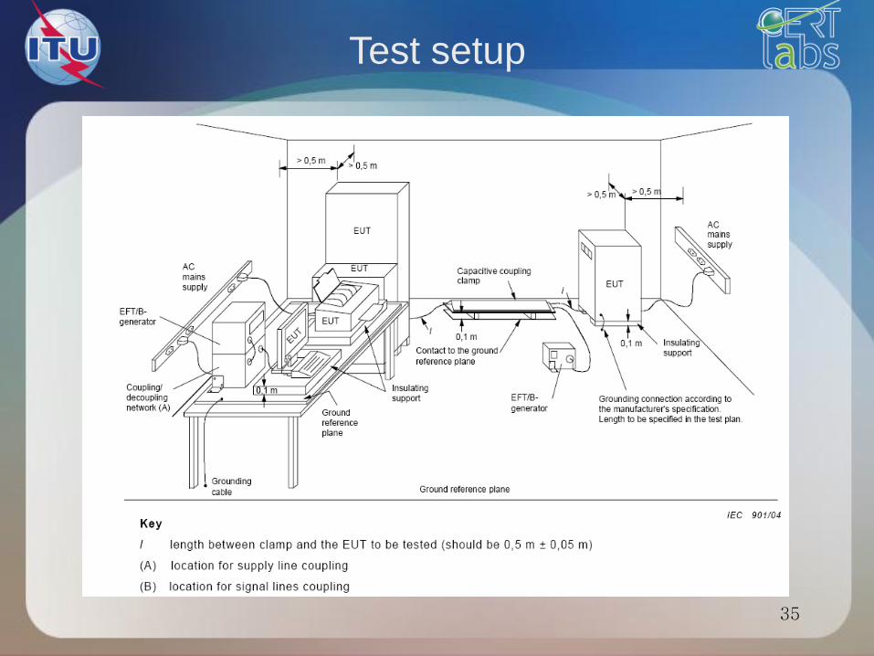
Test setup
32
• Table-top equipment : EUT located 0,1 m above
the ground plane.
• The test generator and CDN placed directly on,
and connected to, the ground plane.
• All cables connected to the EUT shall be placed
on the insulation support 0,1 m above the ground
reference plane.
33
Test setup
• Either a direct coupling network or a capacitive
clamp shall be used for the application of the test
voltages.
• Decoupling networks shall be used to protect
auxiliary equipment and public networks.

Test procedure
34
• The test procedure includes:
• the verification of the laboratory reference
conditions;
• the preliminary verification of the correct
operation of the equipment;
• the execution of the test;
• the evaluation of the test results.
35
Test setup
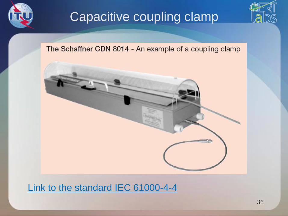
Capacitive coupling clamp
36
Link to the standard IEC 61000-4-4
Surge
IEC 61000-4-5
37

The surge phenomenum
38
Surge effects
• Surges impinging on electronic equipment may cause
hardware damage and complete failure, or in lesser cases
, operational upset.
• Below some level dependent on equipment design, no
effect is observed.
• Above this level, a surge may cause the operation of the
equipment to change state
39
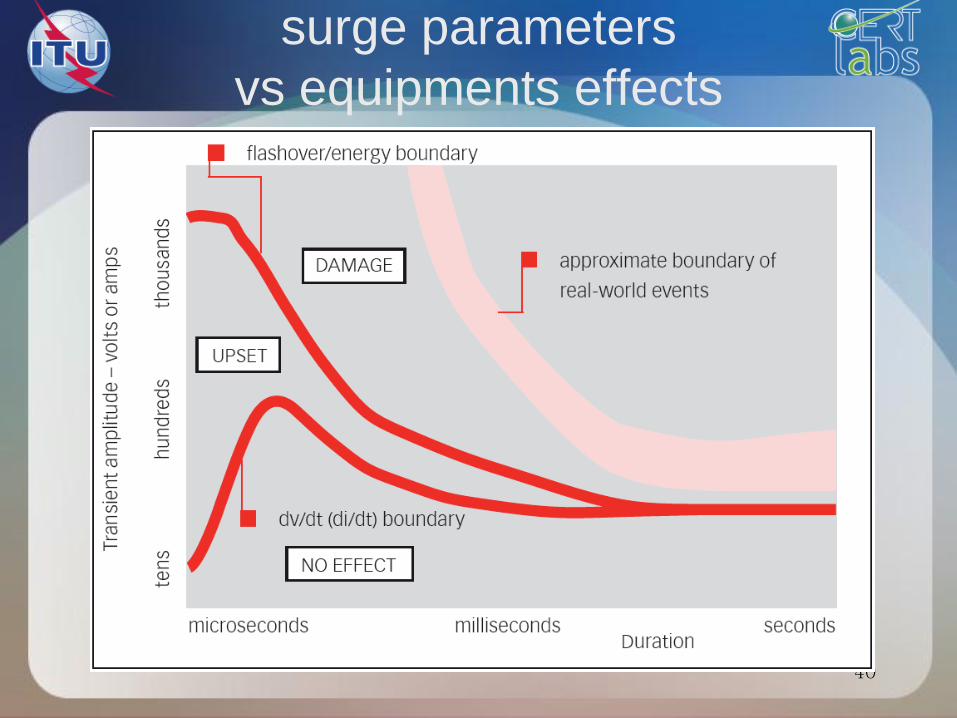
surge parameters
vs equipments effects
40
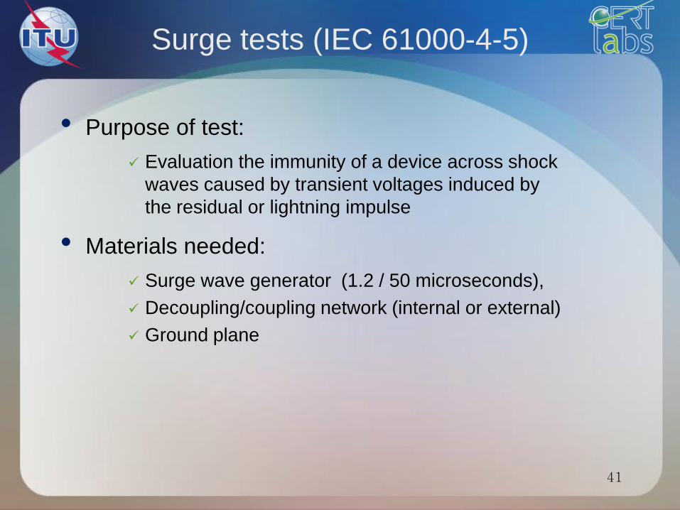
Surge tests (IEC 61000-4-5)
• Purpose of test:
Evaluation the immunity of a device across shock
waves caused by transient voltages induced by
the residual or lightning impulse
• Materials needed:
Surge wave generator (1.2 / 50 microseconds),
Decoupling/coupling network (internal or external)
Ground plane
41
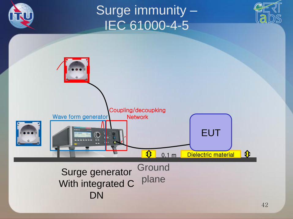
Surge immunity –
IEC 61000-4-5
42
Surge generator
With integrated C
DN
Wave form generator Coupling/decoupking
Network
Ground
plane
Dielectric material 0.1 m
EUT
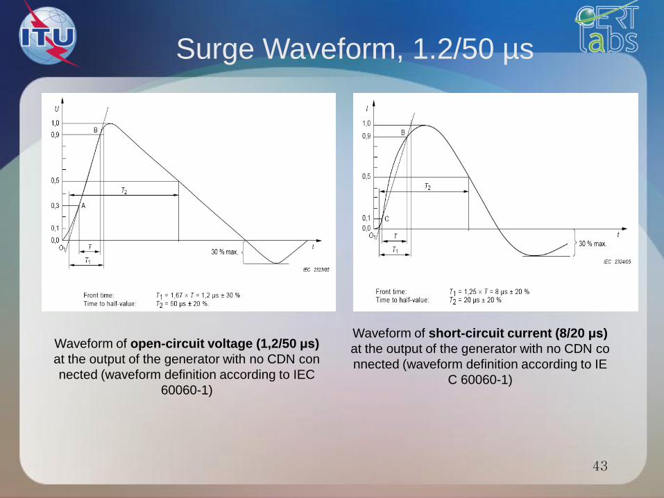
Surge Waveform, 1.2/50 µs
43
Waveform of open-circuit voltage (1,2/50 μs)
at the output of the generator with no CDN con
nected (waveform definition according to IEC
60060-1)
Waveform of short-circuit current (8/20 μs)
at the output of the generator with no CDN co
nnected (waveform definition according to IE
C 60060-1)
44
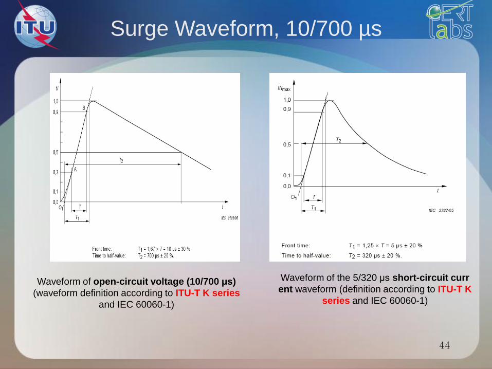
Surge Waveform, 10/700 µs
Waveform of open-circuit voltage (10/700 μs)
(waveform definition according to ITU-T K series
and IEC 60060-1)
Waveform of the 5/320 μs short-circuit curr
ent waveform (definition according to ITU-T K
series and IEC 60060-1)
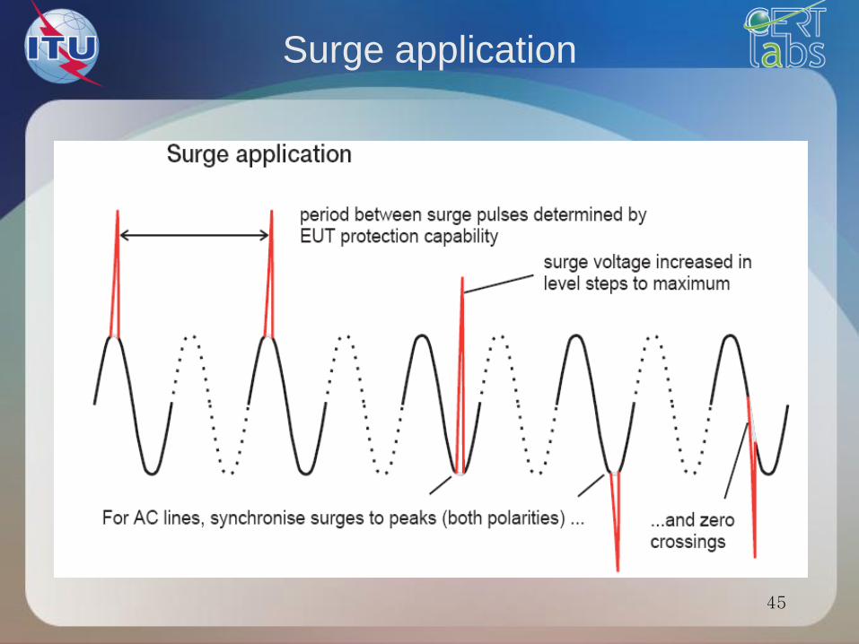
Surge application
45
46
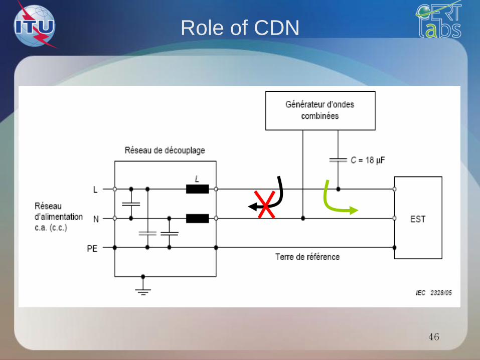
Role of CDN

47
Performance Criteria
for Immunity Tests
Results of immunity tests are classified into four categories:
• Performance Criteria A – ‘Performance within specification limits’
• Performance Criteria B – ‘Temporary degradation which is self-
recoverable’
• Performance Criteria C – ‘Temporary degradation which requires
operator intervention’
•Performance Criteria D – ‘Loss of function which is not recoverable’
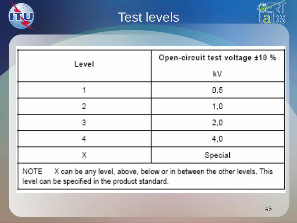
48
Test levels

Standards calls
49
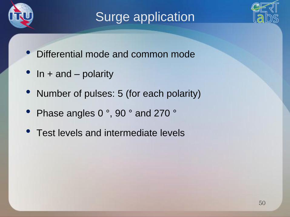
50
Surge application
• Differential mode and common mode
• In + and – polarity
• Number of pulses: 5 (for each polarity)
• Phase angles 0 °, 90 ° and 270 °
• Test levels and intermediate levels

Surge Procedure
• Apply at least five positive and five negative surges at
each coupling point
• Wait for at least a minute between applying each surge, to
allow time for any protection devices to recover
• For ac mains,
• Apply the surges line to line (three combinations for 3-phase
delta, six for 3-phase star, one for single phase) and line to
earth (two combinations for single phase, three for 3-phase
delta, four for 3-phase star)
• Synchronise the surges to the zero crossings and the
positive and negative peaks of the mains supply (four phase
values), and apply five pulses in each polarity at each phase
• Increase the test voltage in steps up to the specified maxi
mum level, so that all lower test levels are satisfied 51

52
Choice of coupling devices
Link to the standard
IEC EN 61000-4-5

Comparision between transient tests
53

54
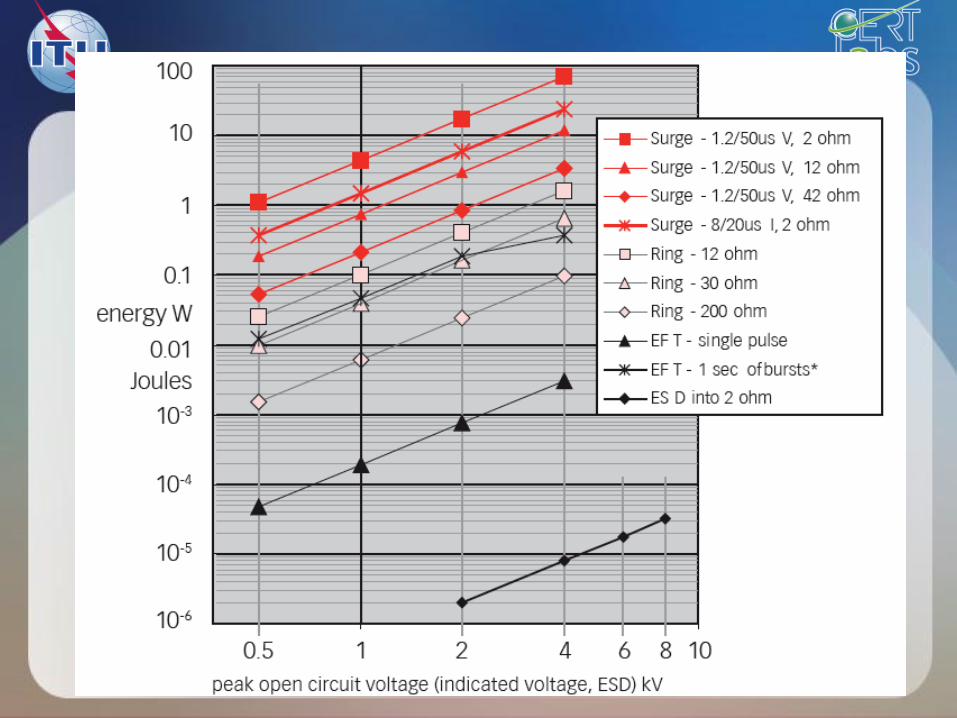
Comparision of transient standards
• The “energy measure” of a given waveform can be
described by
• ESD : waveform magnitude in ns
• EFT : waveform magnitude in ns
• Surge : waveform magnitude in µs
Surge test is more energetic than ESD and EFT
55
Immunity tests
2 – LF and RF phenomena
56

RF coupling phenomenum
57
RF emetters
Radiated immunity
IEC 61000-4-3
58

Radiated immunity
(IEC 61000-4-3)
59
• Test purpose
Evaluate the performance of a device submitted to
radiated RF field
• Needed instruments:
RF generator
Power amplifier
Directional coupler
Power meter
Antenna(s)
Field-meter

60
Antenna
Generator
Power amplifi
er
GPIB Field
meter
Optic fiber Field
uniformity
Radiated immunity – IEC 61000-4-3
Overview

61
Performance Criteria
for Immunity Tests
Results of immunity tests are classified into four categories:
• Performance Criteria A – ‘Performance within specification limits’
• Performance Criteria B – ‘Temporary degradation which is self-
recoverable’
• Performance Criteria C – ‘Temporary degradation which requires
operator intervention’
•Performance Criteria D – ‘Loss of function which is not recoverable’
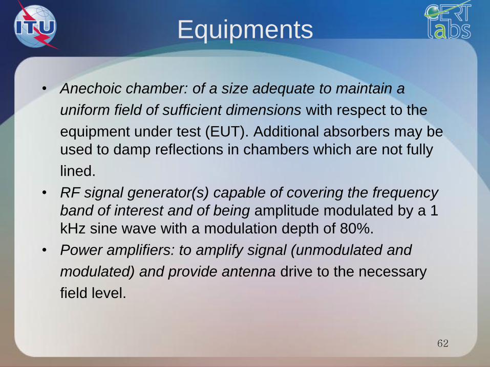
Equipments
• Anechoic chamber: of a size adequate to maintain a
uniform field of sufficient dimensions with respect to the
equipment under test (EUT). Additional absorbers may be
used to damp reflections in chambers which are not fully
lined.
• RF signal generator(s) capable of covering the frequency
band of interest and of being amplitude modulated by a 1
kHz sine wave with a modulation depth of 80%.
• Power amplifiers: to amplify signal (unmodulated and
modulated) and provide antenna drive to the necessary
field level.
62

Equipments
• Field generating antennas: biconical, log periodic, horn or
any other linearly polarized antenna system capable of
satisfying frequency requirements.
• An isotropic field sensor with adequate immunity of any
head amplifier and optoelectronics to the field strength to
be measured, and a fibre optic link to the indicator outside
the chamber.
• Associated equipment to record the power levels
necessary for the required field strength and to control the
generation of that level for testing.
63
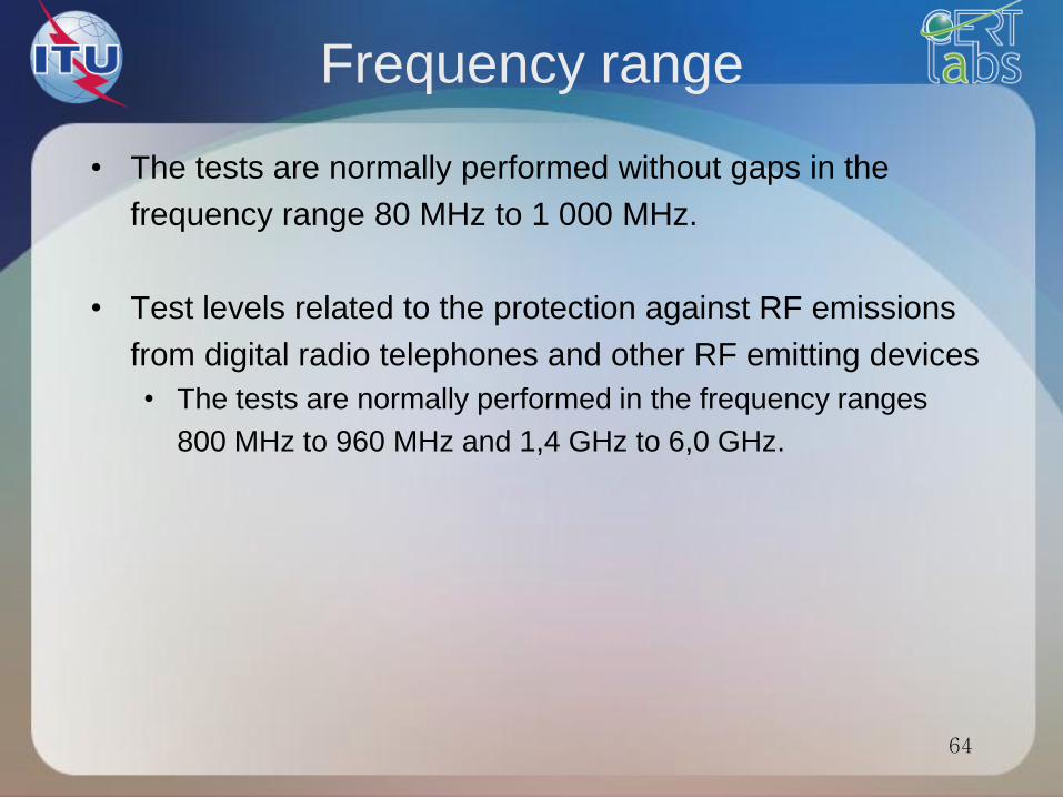
Frequency range
• The tests are normally performed without gaps in the
frequency range 80 MHz to 1 000 MHz.
• Test levels related to the protection against RF emissions
from digital radio telephones and other RF emitting devices
• The tests are normally performed in the frequency ranges
800 MHz to 960 MHz and 1,4 GHz to 6,0 GHz.
64
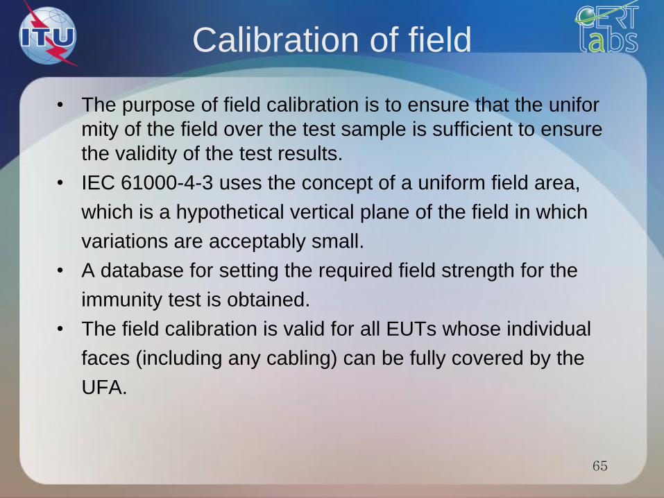
Calibration of field
• The purpose of field calibration is to ensure that the unifor
mity of the field over the test sample is sufficient to ensure
the validity of the test results.
• IEC 61000-4-3 uses the concept of a uniform field area,
which is a hypothetical vertical plane of the field in which
variations are acceptably small.
• A database for setting the required field strength for the
immunity test is obtained.
• The field calibration is valid for all EUTs whose individual
faces (including any cabling) can be fully covered by the
UFA.
65
Calibration of field
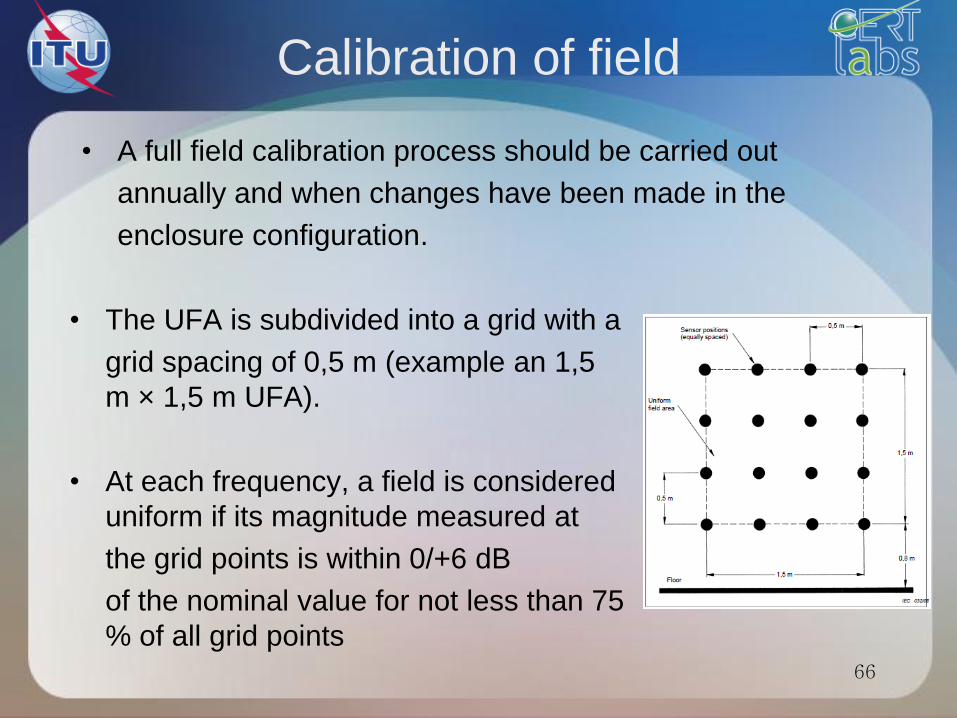
• A full field calibration process should be carried out
annually and when changes have been made in the
enclosure configuration.
66
• The UFA is subdivided into a grid with a
grid spacing of 0,5 m (example an 1,5
m × 1,5 m UFA).
• At each frequency, a field is considered
uniform if its magnitude measured at
the grid points is within 0/+6 dB
of the nominal value for not less than 75
% of all grid points
Calibration of field
• Calibration is performed at 1.8 times the desired field
strength.
• For testing at 10V/m the calibration is run at 18V/m
• The reason of running a test at 1.8x the level is to verify
the RF amplifier has the ability to reach the required field
when the 80% 1KHz Amplitude Modulation is applied.
• An EMC Lab performing testing at multiple levels 1V/m,
3V/m, 10V/m, 30V/m, and/or others, they need only to
perform the calibration at 1.8x the max level they will test
to and then they can scale the power down.
67

AM modulation
68

Considerations for
equipments choice • Select an antenna to use.
• Frequency range
• Power handling
• Beam width & gain
• Select the correct amplifier
• Use calculated power to select the correct amplifier
• Needs to be selected at the 1dB compression point
• Calculate power requirements
• Antenna data: based on measured data or gain
• Calculate out all loses between amplifier and antenna
• Cables, directional coupler and connectors
• Intended test distance (1 to 3 meters)
69

70
Performance Criteria
for Immunity Tests
Results of immunity tests are classified into four categories:
• Performance Criteria A – ‘Performance within specification limits’
• Performance Criteria B – ‘Temporary degradation which is self-
recoverable’
• Performance Criteria C – ‘Temporary degradation which requires
operator intervention’
•Performance Criteria D – ‘Loss of function which is not recoverable’
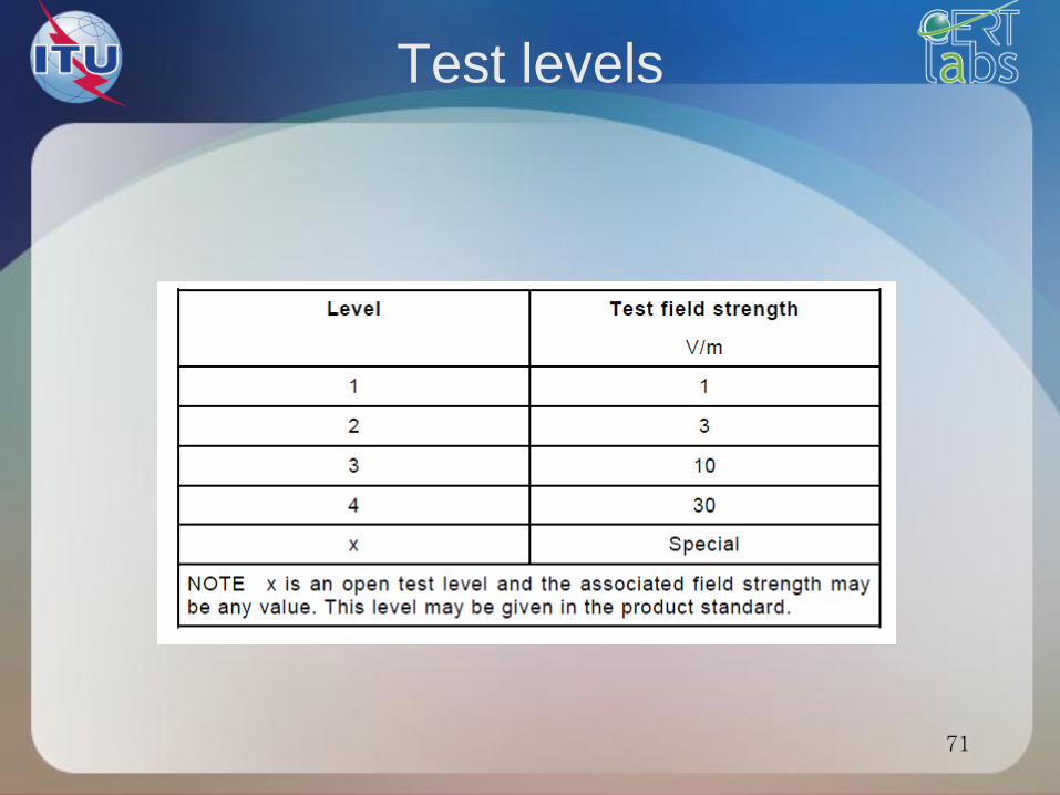
Test levels
71
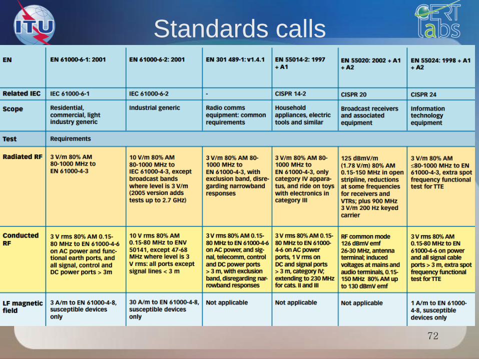
Standards calls
72

Field strength
• The resultant field is computed as folows:
• p is the radiated power
• d is the distance between the antenna and the field mesure
73
d
pe
30

Conducted immunity
IEC 61000-4-6
74

RF coupling phenomenum
75
RF emetters
Radiated immunity
(IEC 61000-4-3)
76
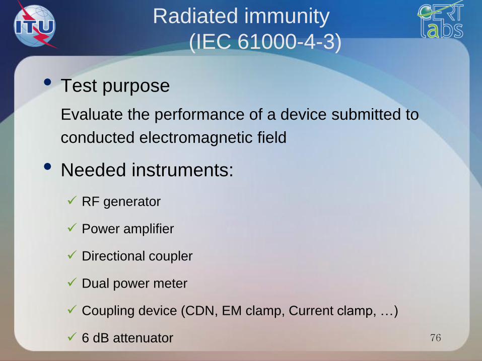
• Test purpose
Evaluate the performance of a device submitted to
conducted electromagnetic field
• Needed instruments:
RF generator
Power amplifier
Directional coupler
Dual power meter
Coupling device (CDN, EM clamp, Current clamp, …)
6 dB attenuator
CDN
77
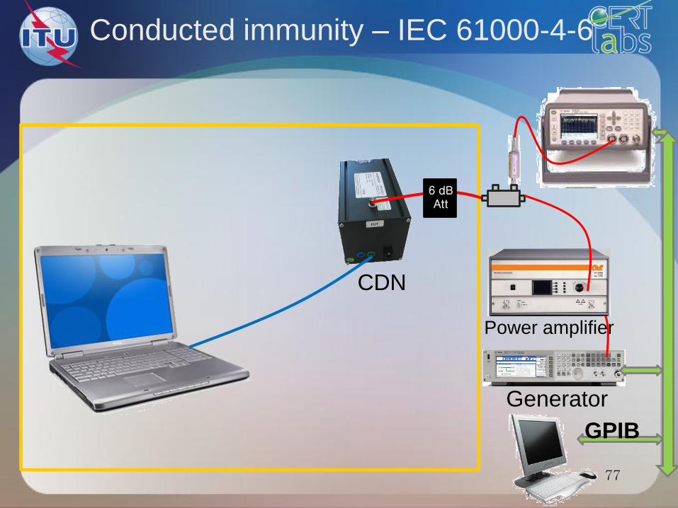
Conducted immunity – IEC 61000-4-6
Generator
Power amplifier
6 dB Att
GPIB
Coupling devices
• Coupling and decoupling devices shall be used for
appropriate coupling of the disturbing signal to the various
cables connected to the EUT and for preventing applied
test signals from affecting other devices, equipment and
systems that are not under test.
• The coupling and decoupling devices can be combined
into one box (a coupling/ decoupling network, CDN) or can
consist of several parts.
• The preferred coupling and decoupling devices are the C
DNs, for reasons of test reproducibility and protection of
the AE.
• However, if they are not suitable or available, other
injection methods can be used. 79
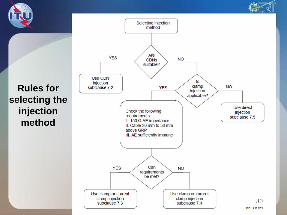
Rules for
selecting the
injection
method
80

Types of CDNs
81
82
Performance Criteria
for Immunity Tests
Results of immunity tests are classified into four categories:
• Performance Criteria A – ‘Performance within specification limits’
• Performance Criteria B – ‘Temporary degradation which is self-
recoverable’
• Performance Criteria C – ‘Temporary degradation which requires
operator intervention’
•Performance Criteria D – ‘Loss of function which is not recoverable’

Typical test levels
83

Standards calls
84
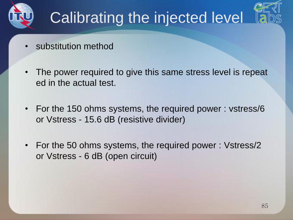
Calibrating the injected level
• substitution method
• The power required to give this same stress level is repeat
ed in the actual test.
• For the 150 ohms systems, the required power : vstress/6
or Vstress - 15.6 dB (resistive divider)
• For the 50 ohms systems, the required power : Vstress/2
or Vstress - 6 dB (open circuit)
85

Immunity to magnetic fields
IEC 61000-4-8
86
87
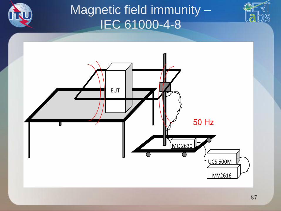
Magnetic field immunity –
IEC 61000-4-8
50 Hz

88
Performance Criteria
for Immunity Tests
Results of immunity tests are classified into four categories:
• Performance Criteria A – ‘Performance within specification limits’
• Performance Criteria B – ‘Temporary degradation which is self-
recoverable’
• Performance Criteria C – ‘Temporary degradation which requires
operator intervention’
•Performance Criteria D – ‘Loss of function which is not recoverable’

Standards calls
89

Immunity to voltage dips
and short interruptions
IEC 61000-4-11
90
91
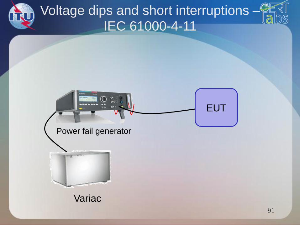
Voltage dips and short interruptions –
IEC 61000-4-11
EUT
Power fail generator
Variac

92
Performance Criteria
for Immunity Tests
Results of immunity tests are classified into four categories:
• Performance Criteria A – ‘Performance within specification limits’
• Performance Criteria B – ‘Temporary degradation which is self-
recoverable’
• Performance Criteria C – ‘Temporary degradation which requires
operator intervention’
•Performance Criteria D – ‘Loss of function which is not recoverable’

93
Voltage dips and short interruptions –
EN 61000-4-11 Overview
94
Emission tests
Emission
CISPR 22 / EN 55022
95
96
ITE functionnality
• An ITE is able to perform:
Receive data from an external source;
Perform treatments
Provide a result

97
Equipements Classes (1)
• The class B ITE is intended primarily for
use in a residential area and may include:
the devices having no fixed location of use, such as portable battery powered or batteries incorporated;
the telecommunication terminal equipment supplied by a telecommunications network;
personal computers and auxiliary devices connected to them.

98
Equipements Classes(2)
• Class A consists of all
other ATI complying with the limits of
disturbance of class A but not those of
class B.
• Can be used in commercial or
industrial environment.

Conducted emissions
CISPR22/EN 55022
99
Required equipments
• For power supply lines:
LISN (Lines Impedance Stabilisation Network)
• For data lines:
ISN (Impedance Stabilisation Network)
• Transient limiter
• EMI receiver or spectrum analyser
• EMI software

101
Conducted emission – CISPR22/
EN 55022
LISN
EMI receiver or
spectrum analyser Transient limiter
GPIB
Frequency (MHz)
dBµV
0.15 300.5 1 5 100
80
10
20
30
40
50
60
70
conduit 55011 CLASSE B Average
conduit 55011 CLASSE B QP

102
Conducted emission test setup
Conducted emissions
Measurement of conducted electromagnetic
disturbances must be made:
• by means of a measuring receiver
• with a peak detector
• in the frequency range 9 kHz to 30 MHz.
104
Conducted limits
• The EUT shall respect the limits of Tables 1 and
2 which include limits on the mean value and limits
on quasi-peak value
• A receiver is used to average value detection and
a quasi-peak detector
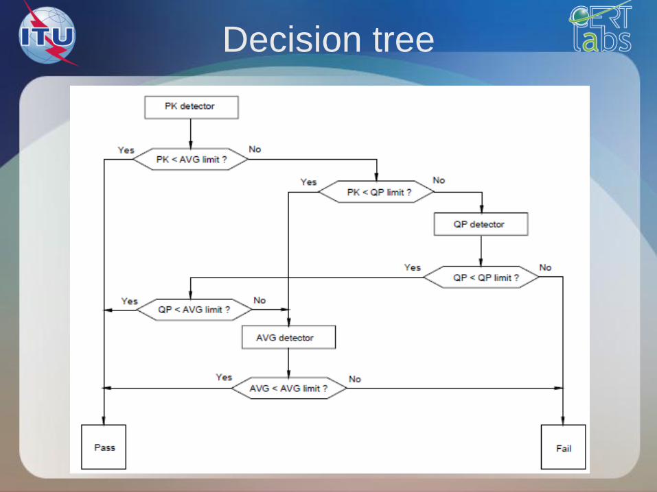
Decision tree
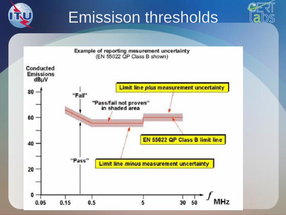
Emissison thresholds
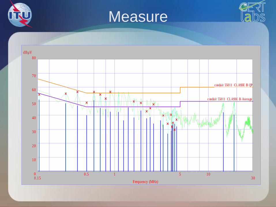
Measure
Frequency (MHz)
dBµV
0.15 300.5 1 5 100
80
10
20
30
40
50
60
70
conduit 55011 CLASSE B Average
conduit 55011 CLASSE B QP

Radiated emissions
CISPR22/EN 55022

Required equipments
• Receiving antennas
• EMI receiver or spectrum analyser
• EMI software
110
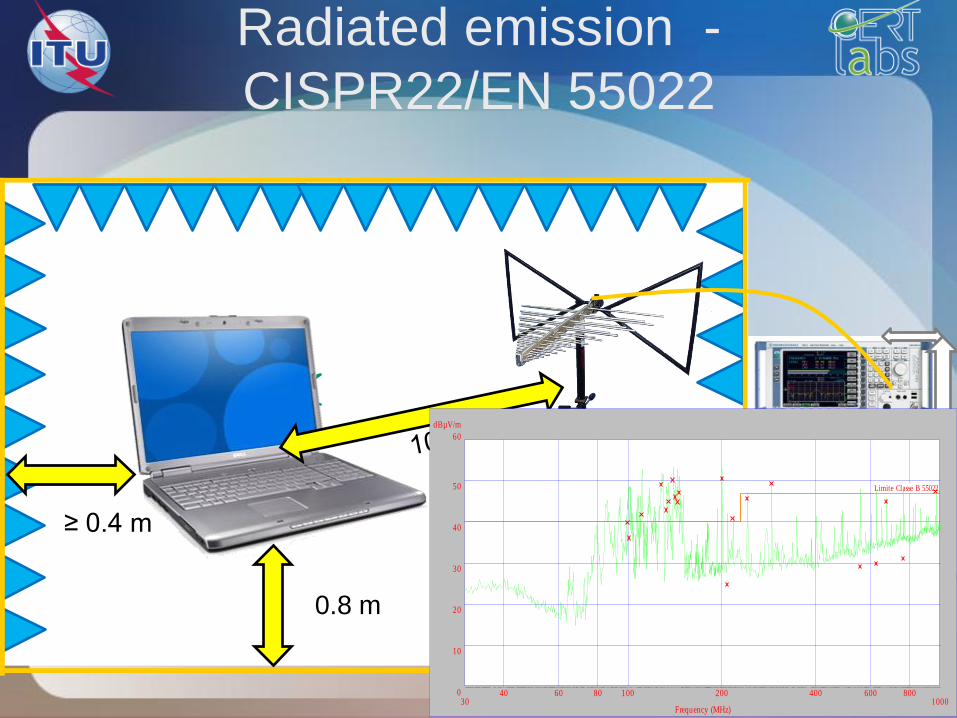
Radiated emission -
CISPR22/EN 55022
EMI receiver or
spectrum analy
ser
GPIB 0.8 m
≥ 0.4 m
Frequency (MHz)
dBµV/m
30 100040 60 80 100 200 400 600 8000
60
10
20
30
40
50 Limite Classe B 55022

Test setup for radiated emission

Radiated emission
• The measurement of radiated electromagnetic disturbance
s must be performed by means of a measuring receiver
equipped with a quasi-peak detector in the frequency
range 30 MHz to 1 GHz or 6 GHz.
• A receiving antenna, associated with a measuring receiver,
is placed at a specific distance from the EUT (test equipme
nt)
112

Radiated EM field measure
• Peak measure to determine the most perturbing condition
• Determining antenna polarisation that most generate
disturbances
• For every frequency :
Determine the antenna hight that captures the maximum
measured level
Determine the angle that generated the maximum of
disturbances
113
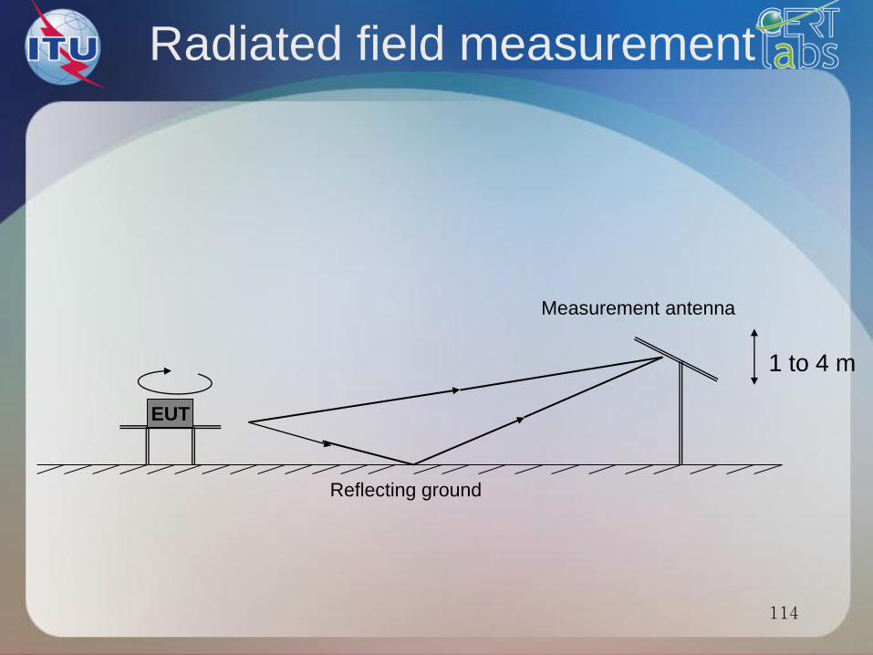
114
EUT
Measurement antenna
Reflecting ground
Radiated field measurement
1 to 4 m

Site de mesure en espace libre
Open area test site
115

Frequency (MHz)
dBµV/m
30 100040 60 80 100 200 400 600 8000
60
10
20
30
40
50 Limite Classe B 55022
Measure
Link to the standard EN 55022

Harmonics emission
IEC 61000-3-2
117
Harmonics emission
Causes
• They are generated by devices that consume non-
sinusoidal current, such as fluorescent lighting or power
supplies (equipment components nonlinear diodes,
thyristors ...)
Effects
• Heating cables (neutral wire three-phase)
• Premature aging of electronic components
118
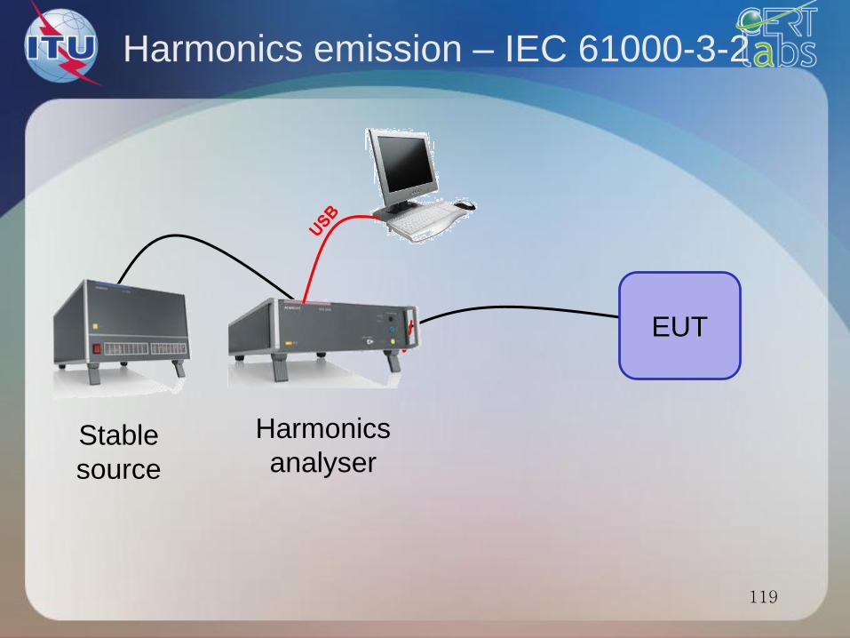
119
EUT
Harmonics emission – IEC 61000-3-2
Harmonics
analyser Stable
source
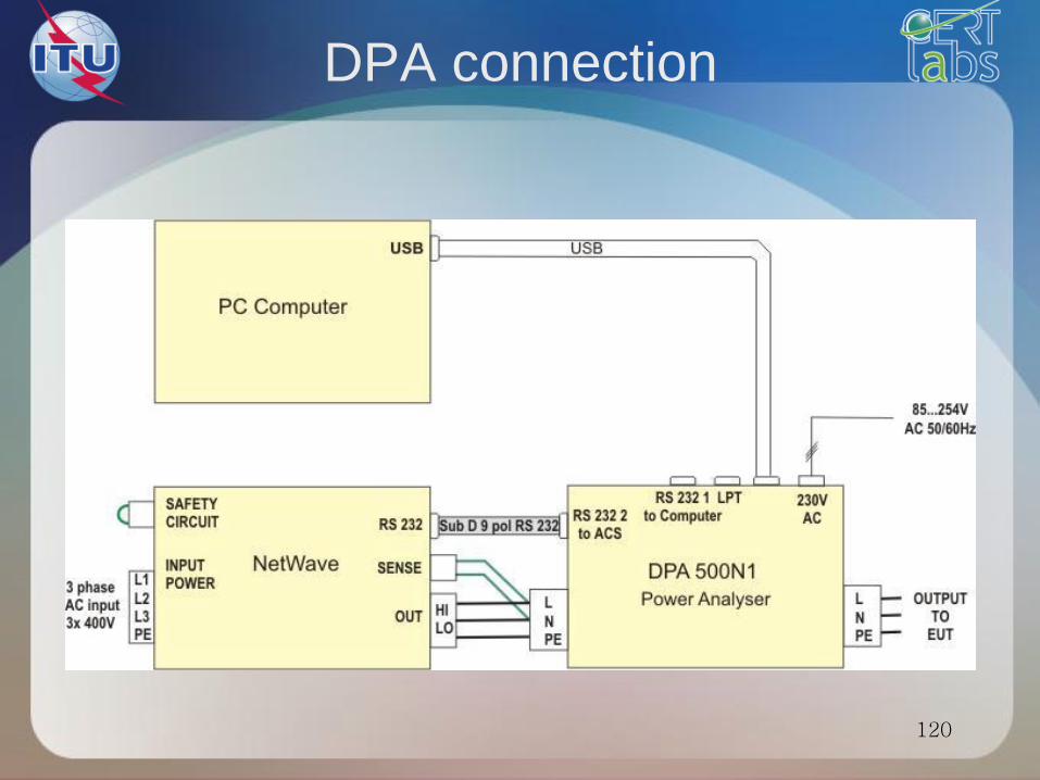
DPA connection
120
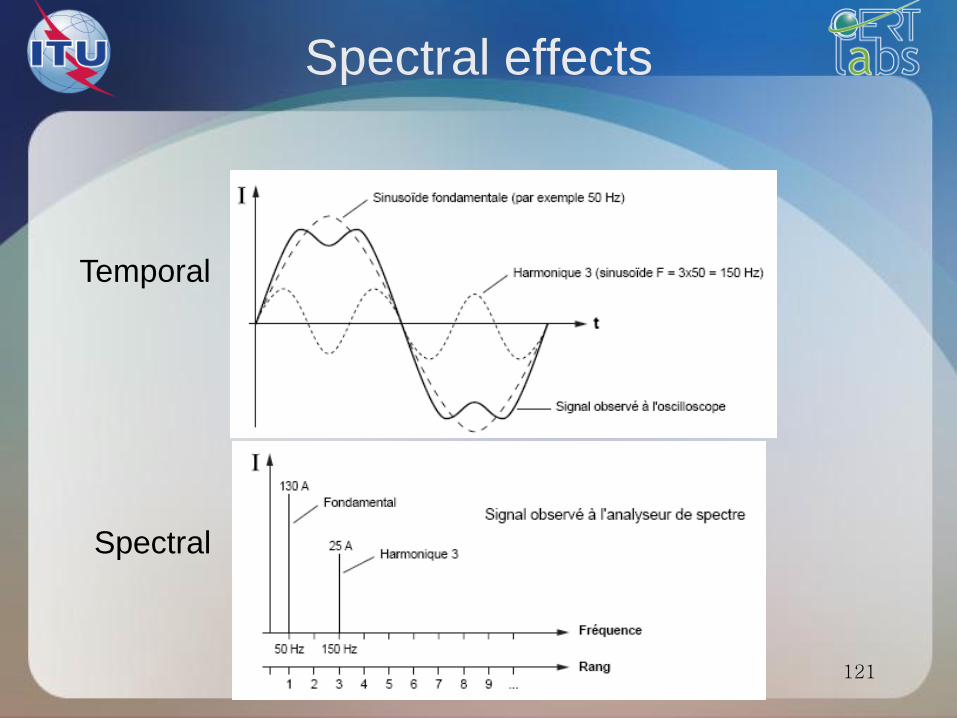
Spectral effects
121
Temporal
Spectral

Time vs frequency representation
122
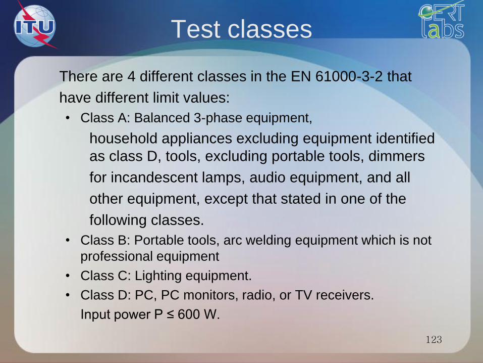
Test classes
There are 4 different classes in the EN 61000-3-2 that
have different limit values:
• Class A: Balanced 3-phase equipment,
household appliances excluding equipment identified
as class D, tools, excluding portable tools, dimmers
for incandescent lamps, audio equipment, and all
other equipment, except that stated in one of the
following classes.
• Class B: Portable tools, arc welding equipment which is not
professional equipment
• Class C: Lighting equipment.
• Class D: PC, PC monitors, radio, or TV receivers.
Input power P ≤ 600 W.
123

124
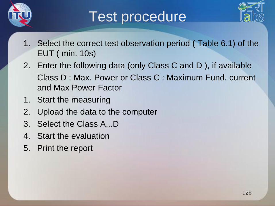
Test procedure
1. Select the correct test observation period ( Table 6.1) of the
EUT ( min. 10s)
2. Enter the following data (only Class C and D ), if available
Class D : Max. Power or Class C : Maximum Fund. current
and Max Power Factor
1. Start the measuring
2. Upload the data to the computer
3. Select the Class A...D
4. Start the evaluation
5. Print the report
125

Data flow
• The DPA measures simultaneeusly on all 2 or 6 input
channels, carries out the Fourier transformation in real
time
• stores all data on the internal hard disk.
• When measuring fluctuations the system generates approx
. 1 Mbyte data per minute on the hard disk. The upload of a
2.5 minute measurement needs less than 20 seconds. An
internal timer in the DPA stops automatically the
measurement.
• The data are ready for upload on the internal hard disk.
• The DPA will overwrite the measurement by starting the
next measurement.
126
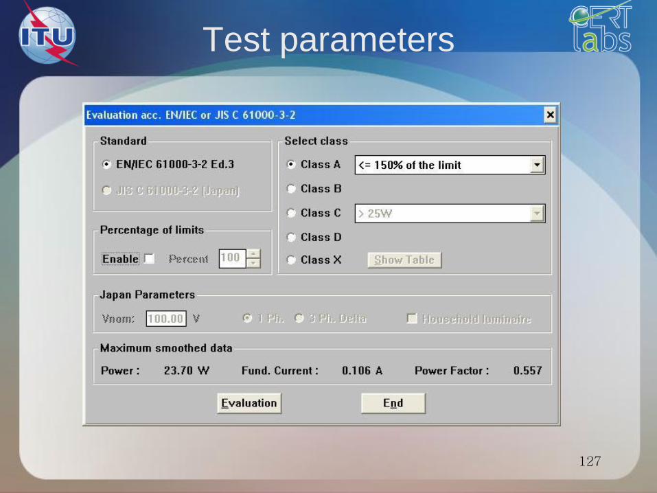
Test parameters
127

Test result
128
Limit values are indicated
and harmonics exceeding
the specified limit are
marked in red colour.

Flickers emission
IEC 61000-3-3
129
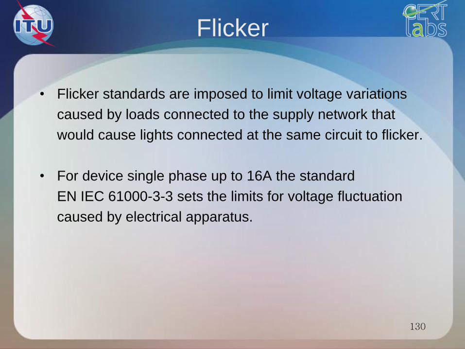
Flicker
• Flicker standards are imposed to limit voltage variations
caused by loads connected to the supply network that
would cause lights connected at the same circuit to flicker.
• For device single phase up to 16A the standard
EN IEC 61000-3-3 sets the limits for voltage fluctuation
caused by electrical apparatus.
130

131
Flickers emission – IEC 61000-3-3
EUT
Flickers analyser Stable
source

132
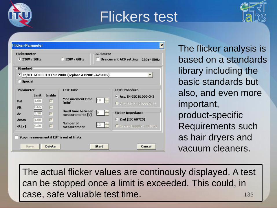
Flickers test
133
The flicker analysis is
based on a standards
library including the
basic standards but
also, and even more
important,
product-specific
Requirements such
as hair dryers and
vacuum cleaners.
The actual flicker values are continously displayed. A test
can be stopped once a limit is exceeded. This could, in
case, safe valuable test time.
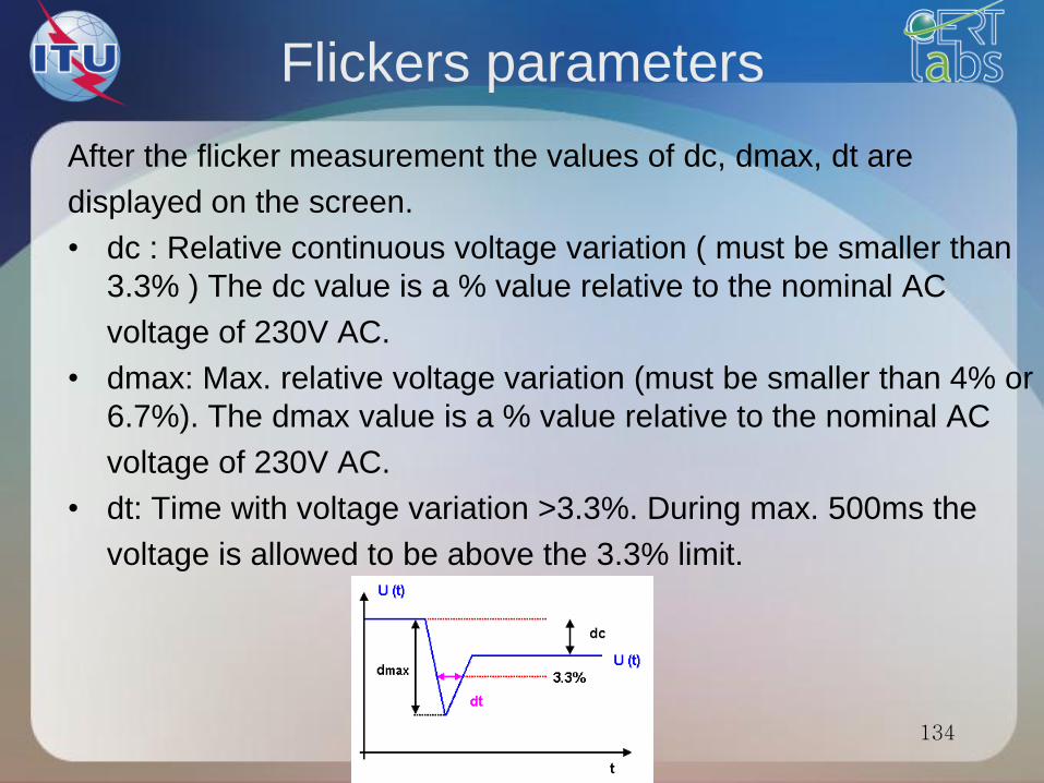
Flickers parameters
After the flicker measurement the values of dc, dmax, dt are
displayed on the screen.
• dc : Relative continuous voltage variation ( must be smaller than
3.3% ) The dc value is a % value relative to the nominal AC
voltage of 230V AC.
• dmax: Max. relative voltage variation (must be smaller than 4% or
6.7%). The dmax value is a % value relative to the nominal AC
voltage of 230V AC.
• dt: Time with voltage variation >3.3%. During max. 500ms the
voltage is allowed to be above the 3.3% limit.
134
Limits
• The limits shall be applicable to voltage fluctuations and
flicker at the supply terminals of the equipment under test:
• The following limits apply:
• the value of Pst shall not be greater than 1,0;
• the value of Plt shall not be greater than 0,65;
• the value of d(t) during a voltage change shall not exceed 3,
3 % for more than 500 ms;
• the relative steady-state voltage change, dc, shall not excee
d 3,3 %;
135
Limits
• the maximum relative voltage change dmax, shall not exceed
a) 4 % without additional conditions;
b) 6 % for equipment which is:
• switched manually, or
• switched automatically more frequently than twice
per day
c) 7 % for equipment which is
• attended whilst in use
• switched on automatically, or is intended to be
switched on manually, no more than twice per day
, and also has either a delayed restart
136
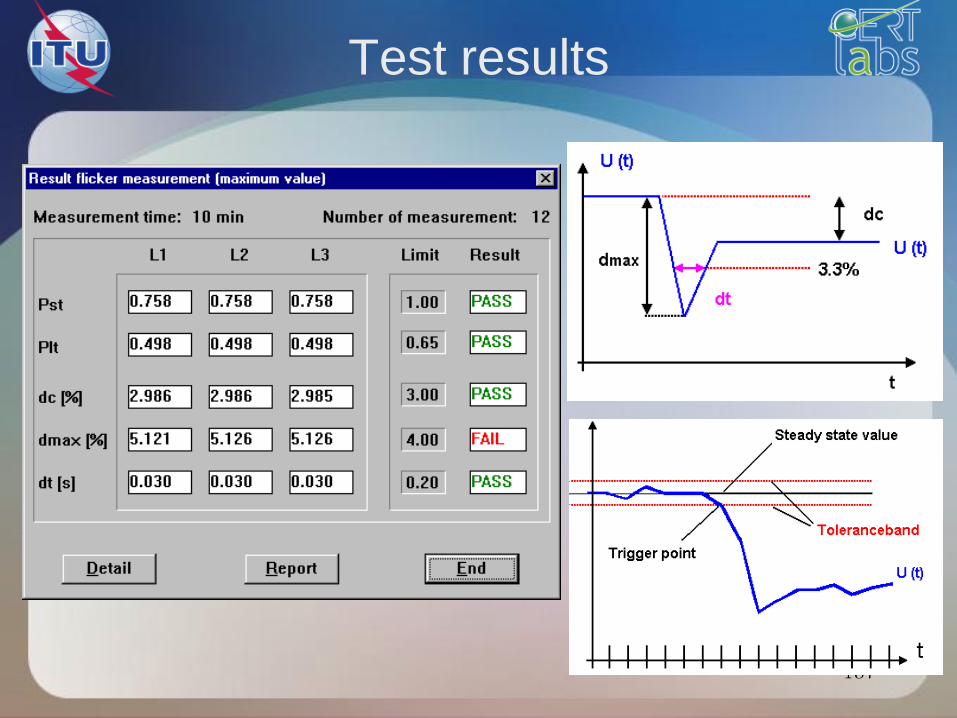
Test results
137

139
Example of a generic standard
EN 61000-6-1

EMC standards
ITU Training on Conformance and Interoperability
for Africain Region
141