EMC CLARiiON CX500/CX500i 2-Gigabit Disk Processor ...€¦ · This guide is part of the EMC®...
120
EMC Corporation Corporate Headquarters: Hopkinton, MA 01748-9103 1-508-435-1000 www.EMC.com EMC CLARiiON CX500/CX500i 2-Gigabit Disk Processor Enclosure (DPE2) HARDWARE REFERENCE P/N 300-001-074 REV A05
Transcript of EMC CLARiiON CX500/CX500i 2-Gigabit Disk Processor ...€¦ · This guide is part of the EMC®...

EMC CorporationCorporate Headquarters:
Hopkinton, MA 01748-9103
1-508-435-1000www.EMC.com
EMC CLARiiONCX500/CX500i
2-Gigabit Disk Processor Enclosure (DPE2)
HARDWARE REFERENCEP/N 300-001-074
REV A05

CX500/CX500i Hardware Referenceii
Copyright © 2004, 2005 EMC Corporation. All rights reserved.
Published August, 2005
EMC believes the information in this publication is accurate as of its publication date. However, the information is subject to change without notice.
THE INFORMATION IN THIS PUBLICATION IS PROVIDED “AS IS.” EMC CORPORATION MAKES NO REPRESENTATIONS OR WARRANTIES OF ANY KIND WITH RESPECT TO THE INFORMATION IN THIS PUBLICATION, AND SPECIFICALLY DISCLAIMS IMPLIED WARRANTIES OF MERCHANTABILITY OR FITNESS FOR A PARTICULAR PURPOSE.
Use, copying, and distribution of any EMC software described in this publication require an applicable software license.
Trademark InformationEMC2, EMC, CLARiiON, Navisphere, and PowerPath are registered trademarks and Access Logix, FLARE, MirrorView, Powerlink, SAN Copy, and SnapView are trademarks of EMC Corporation.
All other trademarks used herein are the property of their respective owners.

CX500/CX500i Hardware Reference iii
Regulatory Notices Product Type(s): X2E, X2E-IThis device complies with Part 15 of the FCC rules. Operation is subject to the following two conditions:
(1) this device may not cause harmful interference, and (2) this device must accept any interference received, including interference that may cause undesired operation.
Testing was done with shielded cables. Therefore, in order to comply with the FCC regulations, you must use shielded cables with your installation. Changes or modifications to this unit not expressly approved by the party responsible for compliance could void the user's authority to operate the equipment.
This equipment has been tested and found to comply with the limits for a Class A digital device, pursuant to Part 15 of the FCC Rules. These limits are designed to provide reasonable protection against harmful interference in a commercial environment. This equipment generates, uses, and can radiate radio frequency energy and, if not installed and used in accordance with the instruction manual, may cause harmful interference to radio communications. Operation of this equipment in a residential area is likely to cause harmful interference in which case the user will be required to correct the interference at his own expense.
This Class A digital apparatus complies with Canadian ICES-003
Cet appareil numérique de la classe A est conforme à la norme NMB-003 du Canada
Manufacturer’s Declaration of Conformity - CE mark
This equipment has been tested and found to comply with the requirements of European Community Council Directives 89/336/EEC, 73/23/EEC, and 98/68/EEC relating to electromagnetic compatibility and product safety respectively.
This product complies with EN55022, CISPR22 and AS/NZS CISPR22 Class A.
This is a Class A product. In a domestic environment this product may cause radio interference in which case the user may be required to take adequate measures.

CX500/CX500i Hardware Referenceiv

CX500/CX500i Hardware Reference v
Preface............................................................................................................................. xi
Warnings and Cautions ........................................................................................ xvii
Chapter 1 About the CX500 and CX500iOverview........................................................................................... 1-2CX500/CX500i Components ......................................................... 1-3
Midplane .................................................................................... 1-6Front Bezel ................................................................................. 1-6Storage Processors (SPs) .......................................................... 1-7Disk Modules ............................................................................ 1-8Power Supply/System Cooling Modules ............................. 1-9Standby Power Supply (SPS) ................................................ 1-10
Chapter 2 Installing a CX500/CX500iRequirements.................................................................................... 2-2
Site Requirements ..................................................................... 2-2Cabling Requirements.............................................................. 2-2Addressing Requirements ...................................................... 2-3Disk Requirements ................................................................... 2-4
Installing a DPE2 in a Cabinet ....................................................... 2-5Warnings and Recommendations .......................................... 2-5
Setting Up an Installed CX500/CX500i DPE2 ............................. 2-7Setting Enclosure Addresses ................................................... 2-7Making Power Connections - ac Power Source ................... 2-8Making Power Connections - dc Power Source ................. 2-11Making Back-End Connections ............................................ 2-13Connecting the CX500 to the External Environment......... 2-17
Contents

CX500/CX500i Hardware Referencevi
Contents
Connecting the CX500i to the External Environment ....... 2-19Make Management LAN Connections................................ 2-20
CX500/CX500i Powerup and Initialization............................... 2-21CX500/CX500i Powerdown......................................................... 2-23
Turning Off the Power - ac Systems..................................... 2-23Turning Off the Power - dc Systems.................................... 2-24
Chapter 3 Servicing and Upgrading a CX500 or CX500iMonitoring CX500/CX500i Status................................................. 3-2Handling FRUs ................................................................................ 3-5
Power Issues and FRUs ........................................................... 3-5Avoiding Electrostatic Discharge (ESD) Damage ................ 3-6Emergency Procedures (Without an ESD Kit)...................... 3-7Precautions When Removing, Installing, or Storing FRUs 3-8
Replacing or Adding a Disk Module ............................................ 3-9Unlocking and Removing the Front Bezel.......................... 3-10Removing a Disk Filler Module ........................................... 3-12Removing a Disk Module...................................................... 3-12Installing a Disk or Filler Module ........................................ 3-13Installing and Locking the Front Bezel................................ 3-15
Replacing a Storage Processor (SP) ............................................. 3-16Removing an SP...................................................................... 3-16Installing an SP ....................................................................... 3-17
Replacing a Power Supply/System Cooling Module .............. 3-18Removing a Power/Cooling Module.................................. 3-18Installing a Power/Cooling Module ................................... 3-20
Chapter 4 The Standby Power Supply (SPS)About the SPS................................................................................... 4-2
Appendix A Technical Specifications and Operating LimitsCX500/CX500i DPE2 Technical Specifications .......................... A-2
Power Requirements............................................................... A-2Size and Weight ....................................................................... A-4Drive Type ................................................................................ A-4DPE2 FC-AL Interface............................................................. A-4
Standards Certification and Compliance ................................... A-7CX500/CX500i - ac Power...................................................... A-7CX500 - dc Power .................................................................... A-8Other Standards (CX500 only)............................................... A-8Fibre Channel Related Standards.......................................... A-9

viiCX500/CX500i Hardware Reference
Contents
Operating Limits ........................................................................... A-9Environmental Recovery ..................................................... A-10Shipping and Storage Requirements.................................. A-10Operational Behavior of dc Power over Voltage Range . A-11
SPS Technical Specifications ...................................................... A-13SPS to SP Interface ................................................................ A-13Power Specifications ............................................................ A-13SPS Operating Limits ........................................................... A-14SPS Shipping and Storage Requirements .......................... A-14Dimensions and Battery Information................................. A-14SPS Standards Certification/Compliance ......................... A-16
Appendix B Customer SupportOverview of Detecting and Resolving Problems ....................... B-2Troubleshooting the Problem ....................................................... B-3Before Calling the Customer Support Center ............................ B-4Documenting the Problem ............................................................ B-5Reporting a New Problem ............................................................ B-6Sending Problem Documentation ................................................ B-7
Glossary........................................................................................................................ g-1
Index ............................................................................................................................... i-1

CX500/CX500i Hardware Referenceviii
Contents
CX500/CX500i Hardware Reference ix
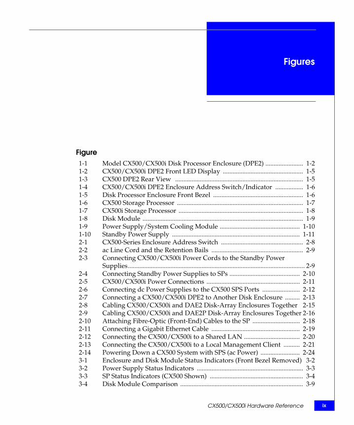
Figure1-1 Model CX500/CX500i Disk Processor Enclosure (DPE2) ....................... 1-21-2 CX500/CX500i DPE2 Front LED Display ................................................. 1-51-3 CX500 DPE2 Rear View .............................................................................. 1-51-4 CX500/CX500i DPE2 Enclosure Address Switch/Indicator ................. 1-61-5 Disk Processor Enclosure Front Bezel ....................................................... 1-61-6 CX500 Storage Processor ............................................................................. 1-71-7 CX500i Storage Processor ............................................................................ 1-81-8 Disk Module .................................................................................................. 1-91-9 Power Supply/System Cooling Module ................................................. 1-101-10 Standby Power Supply .............................................................................. 1-112-1 CX500-Series Enclosure Address Switch .................................................. 2-82-2 ac Line Cord and the Retention Bails ........................................................ 2-92-3 Connecting CX500/CX500i Power Cords to the Standby Power
Supplies............................................................................................................ 2-92-4 Connecting Standby Power Supplies to SPs ........................................... 2-102-5 CX500/CX500i Power Connections ......................................................... 2-112-6 Connecting dc Power Supplies to the CX500 SPS Ports ....................... 2-122-7 Connecting a CX500/CX500i DPE2 to Another Disk Enclosure ......... 2-132-8 Cabling CX500/CX500i and DAE2 Disk-Array Enclosures Together 2-152-9 Cabling CX500/CX500i and DAE2P Disk-Array Enclosures Together 2-162-10 Attaching Fibre-Optic (Front-End) Cables to the SP ............................. 2-182-11 Connecting a Gigabit Ethernet Cable ...................................................... 2-192-12 Connecting the CX500/CX500i to a Shared LAN .................................. 2-202-13 Connecting the CX500/CX500i to a Local Management Client .......... 2-212-14 Powering Down a CX500 System with SPS (ac Power) ........................ 2-243-1 Enclosure and Disk Module Status Indicators (Front Bezel Removed) 3-23-2 Power Supply Status Indicators ................................................................. 3-33-3 SP Status Indicators (CX500 Shown) ......................................................... 3-43-4 Disk Module Comparison ........................................................................... 3-9
Figures

x CX500/CX500i Hardware Reference
Figures
3-5 Unlocking and Removing the Front Bezel ............................................... 3-113-6 Removing a Disk Filler Module ................................................................ 3-123-7 Removing a Disk Module .......................................................................... 3-133-8 Installing a Disk or Filler Module ............................................................. 3-143-9 Installing and Locking the Front Bezel .................................................... 3-153-10 Removing an SP ........................................................................................... 3-163-11 Installing an SP ............................................................................................ 3-173-12 Unplugging the ac Power Cord ................................................................ 3-193-13 Unplugging the dc Power Cord ................................................................ 3-193-14 Removing a Power Supply/System Cooling Module ........................... 3-203-15 Installing a Power/Cooling Module ........................................................ 3-213-16 Plugging in the Power Cord ...................................................................... 3-224-1 CX500/CX500i SPS Rear Panel ................................................................... 4-24-2 SPS Installation, Front and Rear Views ...................................................... 4-4A-1 Typical SPS Self-Discharge Levels at Different Storage Temperatures A-15B-1 Problem Detection and Resolution Process .............................................. B-2

CX500/CX500i Hardware Reference xi
Preface
As part of an effort to improve and enhance the performance and capabilities of its product line, EMC from time to time releases revisions of its hardware and software. Therefore, some functions described in this guide may not be supported by all revisions of the software or hardware currently in use. For the most up-to-date information on product features, refer to your product release notes.
If a product does not function properly or does not function as described in this guide, please contact your EMC representative.
This guide is part of the EMC® CLARiiON® CX500-Series 2-gigabit disk processor enclosure (DPE2) documentation set, and is intended for use by system administrators and other qualified technical personnel during installation, setup, and maintenance of the storage system.
Readers of this guide are expected to be familiar with basic computer hardware installation and field-replaceable unit (FRU) installation.
How This Manual IsOrganized
Chapter 1 Introduces the CX500-Series DPE2 components.
Chapter 2 Explains requirements and describes how to cable the CX500/CX500i to a server and to other rackmounted disk enclosures.
Chapter 3 Describes how to replace FRUs such as disk modules, power supplies, and storage processors.
Chapter 4 Describes the standby power supply (SPS).

xii CX500/CX500i Hardware Reference
Preface
RelatedDocumentation
40U-C Cabinet Setup Guide (P/N 300-001-555)
Site Preparation and Unpacking Guide for the 40U-C Cabinet (P/N 300-001-556)
EMC Rails and Enclosures (CX-Series Storage Systems) Field Installation Guide (P/N 300-001-799)
CX500 2-Gigabit Fibre Channel Disk Processor Enclosure (DPE2) Setup Guide (P/N 300-001-275)
CX500i 2-Gigabit iSCSI Disk Processor Enclosure (DPE2) Setup Guide (P/N 300-001-924)
EMC 2-Gigabit Disk-Array Enclosure (DAE2) Setup Guide (P/N 014003104)
EMC 2-Gigabit Disk-Array Enclosure (DAE2) Hardware Reference (P/N 014003048)
EMC CLARiiON 2-Gigabit Point-to-Point Disk Enclosure (DAE2P) Setup Guide (P/N 300-002-408)
EMC CLARiiON 2-Gigabit Point-to-Point Disk Enclosure (DAE2P) Hardware Reference (P/N 300-002-407)
EMC Navisphere Manager Administrator’s Guide (P/N 069001125)
EMC CLARiiON CX300, CX300i, CX500, CX500i, and CX700 Storage Systems Configuration Planning Guide (P/N 300-001-273)
EMC Navisphere Security Administrator’s Guide (P/N 069001124)
EMC Installation Roadmap for CX-Series, AX-Series, and FC-Series Storage Systems (P/N 069001166)
Appendix A Lists the CX500-Series technical specifications.
Appendix B Reviews the EMC process for detecting and resolving software problems, and provides essential questions that you should answer before contacting the EMC Customer Support Center.
Glossary Defines terms used in the documentation.
CX500/CX500i Hardware Reference xiii
Preface
Conventions Used inThis Manual
EMC uses the following conventions for notes, cautions, warnings, and danger notices.
A note presents information that is important, but not hazard-related.
CAUTION!A caution contains information essential to avoid damage to the system or equipment. The caution may apply to hardware or software.
WARNING
A warning contains information essential to avoid a hazard that can cause severe personal injury, death, or substantial property damage if you ignore the warning.
DANGER
A danger notice contains information essential to avoid a hazard that will cause severe personal injury, death, or substantial property damage if you ignore the warning.
Typographical ConventionsThis manual uses the following format conventions:
This typeface
Indicates text (including punctuation) that you type verbatim, all commands, pathnames, filenames, and directory names. It indicates the name of a dialog box, field in a dialog box, menu, menu option, or button.
This typeface Represents variables for which you supply the values; for example, the name of a directory or file, your username or password, and explicit arguments to commands.
This typeface
Represents a system response (such as a message or prompt), a file or program listing.

xiv CX500/CX500i Hardware Reference
Preface
Finding CurrentInformation
The most up-to-date information about the CX500-Series is posted on the EMC Powerlink™ website. We recommend that you download the latest information before you install or service your DPE2. If you purchased this product from an EMC reseller and you cannot access Powerlink, the latest product information should be available from your reseller.
To access EMC Powerlink, use the following link:
http://powerlink.emc.com
After you log in, select Support > Document Library and find the following:
The FLARE™ release notes
The latest version of this reference.
EMC Installation Roadmap for CX-Series, AX-Series, and FC-Series Storage Systems, which provides a checklist of the tasks that you must complete to install your storage system in a storage area network (SAN) or direct attach configuration.
Where to Get Help For questions about technical support, call your local sales office or service provider.
If you have a valid EMC service contract, contact EMC Customer Service at:
Follow the voice menu prompts to open a service call and select the applicable product support.
x > y Represents a menu path. For example, Operations > Poll All Storage Systems tells you to select Poll All Storage Systems on the Operations menu.
[ ] Encloses optional entries.
| Separates alternative parameter values; for example:LUN-name | LUN-number means you can use either the LUN-name or the LUN-number.
United States: (800) 782-4362 (SVC-4EMC)Canada: (800) 543-4782 (543-4SVC)Worldwide: (508) 497-7901

CX500/CX500i Hardware Reference xv
Preface
Sales and CustomerService Contacts
For the list of EMC sales locations, please access the EMC home page at:
http://www.EMC.com/contact/
For additional information on the EMC products and services available to customers and partners, refer to the EMC Powerlink™ website at:
http://powerlink.EMC.com
Your Comments Your suggestions will help us continue to improve the accuracy, organization, and overall quality of the user publications. Please send a message to [email protected] with your opinions of this guide.

xvi CX500/CX500i Hardware Reference
Preface
CX500/CX500i Hardware Reference xvii
The following warnings and cautions pertain throughout this guide.
WARNING Trained service personnel only
Ground circuit continuity is vital for safe operation of the machine. Never operate the machine with grounding conductors disconnected. Remember to reconnect any grounding conductors removed for or during any installation procedure.
ATTENTION Resérvé au personnel autorisé.
Un circuit de terre continu est essentiel en vue du fonctionnement sécuritaire de l'apareil. Ne jamais mettre l'appareil en marche lorsque le conducteur de mise a la terre est débranché.
WARNUNG Nur für Fachpersonal.
STROMSTREUVERLUST: Gerät muss geerdet werden, bevor es am Stromnetz angeschlossen wird.
Warnings andCautions

xviii CX500/CX500i Hardware Reference
Warnings and Cautions
WARNING
Trained personnel are advised to exercise great care at all times when working on the unit. Remember to:
Remove rings, watches, or other jewelry and neckties before you begin any procedures.
Use caution near any moving part and any part that may start unexpectedly such as fans, motors, solenoids, and so on.
Always use the correct tools for the job.
Always use the correct replacement parts.
Keep all paperwork, including incident reports, up to date, complete, and accurate.
Static Precautions EMC incorporates state-of-the-art technology in its designs, including the use of LSI and VLSI components. These chips are very susceptible to damage caused by static discharge and need to be handled accordingly.
CAUTION!Before handling printed-circuit boards or other parts containing LSI and/or VLSI components, observe the following precautions:
Store all printed-circuit boards in antistatic bags. Use a ground strap whenever you handle a printed-circuit
board. Unless specifically designed for nondisruptive replacement,
never plug or unplug printed-circuit boards with the power on. Severe component damage may result.

CX500/CX500i Hardware Reference xix
Warnings and Cautions
Replacing the SP BatteryA lithium battery on the storage processor powers the real-time clock (RTC) for three to four years in the absence of power. Only trained personnel should change or replace this battery.
WARNING
Danger of explosion if battery is incorrectly replaced. Replace only with the same or equivalent type recommended by the equipment manufacturer. Discard used batteries according to manufacturer's instructions.

xx CX500/CX500i Hardware Reference
Warnings and Cautions

About the CX500 and CX500i 1-1
1
This chapter discusses the EMC® CLARiiON® CX500 and CX500i 2-gigabit disk processor enclosures (DPE2). Major topics include
Overview.............................................................................................1-2 CX500/CX500i Components ............................................................1-3
About the CX500 andCX500i

1-2 CX500/CX500i Hardware Reference
About the CX500 and CX500i
OverviewThe CX500 and CX500i 2-gigabit disk processor enclosures (DPE2), shown in Figure 1-1, are intelligent, highly available, high-performance, high-capacity disk-array storage systems. The CX500-Series enclosure is only 3U (5.25 inches) high, but can include 15 high-performance Fibre Channel hard disk drives. The system’s modular, scalable design provides additional disk storage as your needs increase. The examples and illustrations in this manual show the DPE2 rackmounted in a standard 40U EMC cabinet.
Figure 1-1 Model CX500/CX500i Disk Processor Enclosure (DPE2)
The CX500 uses a Fibre Channel arbitrated loop (FC-AL) or Fibre Channel switch (FC-SW) as its interconnect interface to arrayed disks and to servers that use the storage system. CX500i systems also use FC-AL within the storage system and attached optional disk array enclosures, but use the iSCSI (Internet Small Computer Systems Interface) protocol for server input/output.
EMC2164
DiskDrive(0 - 14)
FrontBezel
RackmountCabinet

CX500/CX500i Components 1-3
About the CX500 and CX500i
A CX500/CX500i can support as many as 7 additional disk-array enclosures (DAEs, also called array modules). A DAE is a basic enclosure without a storage processor (SP) that includes either high-performance Fibre Channel or economical ATA disks. The CX500/CX500i and a maximum of 7 additional DAEs support up to 120 disk modules in a single disk-array storage system. You can place the DAEs in the same cabinet as the CX500/CX500i, or in one or more separate cabinets.
CX-Series storage systems support both 2-gigabit disk-array enclosures (DAE2s) and 2-gigabit point-to-point disk-array enclosures (DAE2Ps).
The CX500 connects to the external Fibre Channel environment using small form factor (SFF) LC optical transceivers on the storage processor. The CX500i connects to a 1-gigabit Ethernet environment using standard RJ45 LAN connectors and Ethernet cables. High-availability features are standard on both models.
Storage group features in the EMC Access Logix™ software option allow you to connect the CX500/CX500i to multiple hosts that may be running different operating systems.
CX500/CX500i Components
Each CX500-Series storage system includes a DPE2 consisting of:
A sheet-metal enclosure with a midplane and front bezel
Two storage processors (SPs)
As many as 15 Fibre Channel disk modules
Two power supply/system cooling modules
Blowers integrated in the power/cooling modules cool the entire enclosure. The CX500/CX500i does not require discrete fan assemblies.
Storage systems using ac source power require two standby power supplies (SPSs).

1-4 CX500/CX500i Hardware Reference
About the CX500 and CX500i
Systems with dc power are intended for use in environments with redundant and highly available power sources (for example, "Central Office" grade power within the telecommunications industry), and dc power provided by the site must meet this requirement. The sudden loss of all incoming dc power to a storage system may cause unexpected abnormal behavior of the storage system and loss of write-cache data.
Any unoccupied disk module slot has a filler module to maintain air flow.
The storage processors, disk modules, power supplies, and filler modules are field-replaceable units (FRUs), which you can add or replace without tools while the storage system is powered up.
The disk modules are FC-AL compliant and support dual-port FC-AL interconnections through the two SPs and their cabling.
The system can continue running in a degraded mode with one operating power supply and a single functioning SP. You should replace a failed FRU as soon as possible.
Figures 1-2 through 1-4 show the enclosure components. Where the enclosure provides slots for two identical components, the components are called component-name A or component-name B, as shown in the illustrations.
For increased clarity, the following figures depict the DPE2 outside of the rack cabinet. Your CX500/CX500i may be installed in a rackmount cabinet as shown in Figure 1-1.
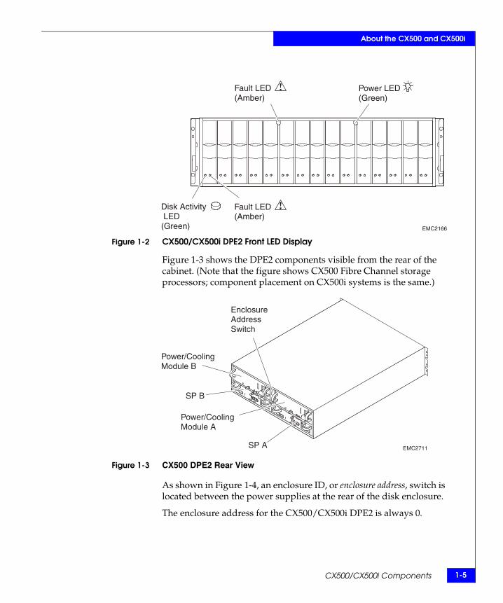
As shown in Figure 1-2, the front LED (light) display contains two status lights for each disk module, and two disk enclosure status lights. The status lights are visible with the front bezel installed.
CX500/CX500i Components 1-5
About the CX500 and CX500i
Figure 1-2 CX500/CX500i DPE2 Front LED Display
Figure 1-3 shows the DPE2 components visible from the rear of the cabinet. (Note that the figure shows CX500 Fibre Channel storage processors; component placement on CX500i systems is the same.)
Figure 1-3 CX500 DPE2 Rear View
As shown in Figure 1-4, an enclosure ID, or enclosure address, switch is located between the power supplies at the rear of the disk enclosure.
The enclosure address for the CX500/CX500i DPE2 is always 0.
EMC2166
Power LED(Green)
Fault LED(Amber)
Fault LED(Amber)
Disk Activity LED(Green)
EMC2711
EnclosureAddressSwitch
Power/CoolingModule A
Power/CoolingModule B
SP A
SP B

1-6 CX500/CX500i Hardware Reference
About the CX500 and CX500i
Figure 1-4 CX500/CX500i DPE2 Enclosure Address Switch/Indicator
The CX500/CX500i status lights are described in Monitoring CX500/CX500i Status on page 3-2.
Midplane The midplane distributes power and signals to all the enclosure components. All FRUs plug directly into midplane connectors.
Front Bezel The front bezel, shown in Figure 1-5, has a keylock, two latch release buttons, and an electromagnetic interference (EMI) shield. You can take off the bezel to remove and install drive modules, but EMI compliance requires a properly installed front bezel.
Figure 1-5 Disk Processor Enclosure Front Bezel
EMC2712
EnclosureAddressSwitch+
_
0
EMC2173
CX500/CX500i Components 1-7
About the CX500 and CX500i
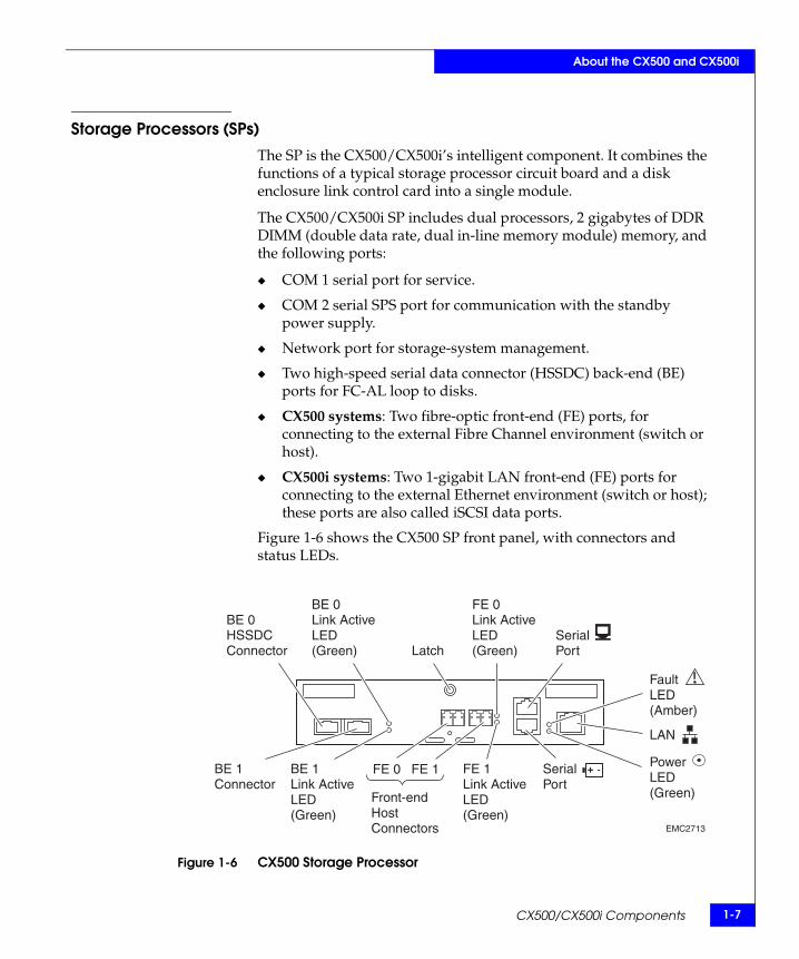
Storage Processors (SPs)The SP is the CX500/CX500i’s intelligent component. It combines the functions of a typical storage processor circuit board and a disk enclosure link control card into a single module.
The CX500/CX500i SP includes dual processors, 2 gigabytes of DDR DIMM (double data rate, dual in-line memory module) memory, and the following ports:
COM 1 serial port for service.
COM 2 serial SPS port for communication with the standby power supply.
Network port for storage-system management.
Two high-speed serial data connector (HSSDC) back-end (BE) ports for FC-AL loop to disks.
CX500 systems: Two fibre-optic front-end (FE) ports, for connecting to the external Fibre Channel environment (switch or host).
CX500i systems: Two 1-gigabit LAN front-end (FE) ports for connecting to the external Ethernet environment (switch or host); these ports are also called iSCSI data ports.
Figure 1-6 shows the CX500 SP front panel, with connectors and status LEDs.
Figure 1-6 CX500 Storage Processor
FE 0 FE 1
Front-endHostConnectors
PowerLED(Green)
BE 0Link ActiveLED(Green)
BE 1Link ActiveLED(Green)
FE 0Link ActiveLED(Green)
FE 1Link ActiveLED(Green)
BE 0HSSDCConnector
BE 1Connector
Latch
FaultLED(Amber)
LAN
+ -SerialPort
SerialPort
EMC2713
1-8 CX500/CX500i Hardware Reference
About the CX500 and CX500i
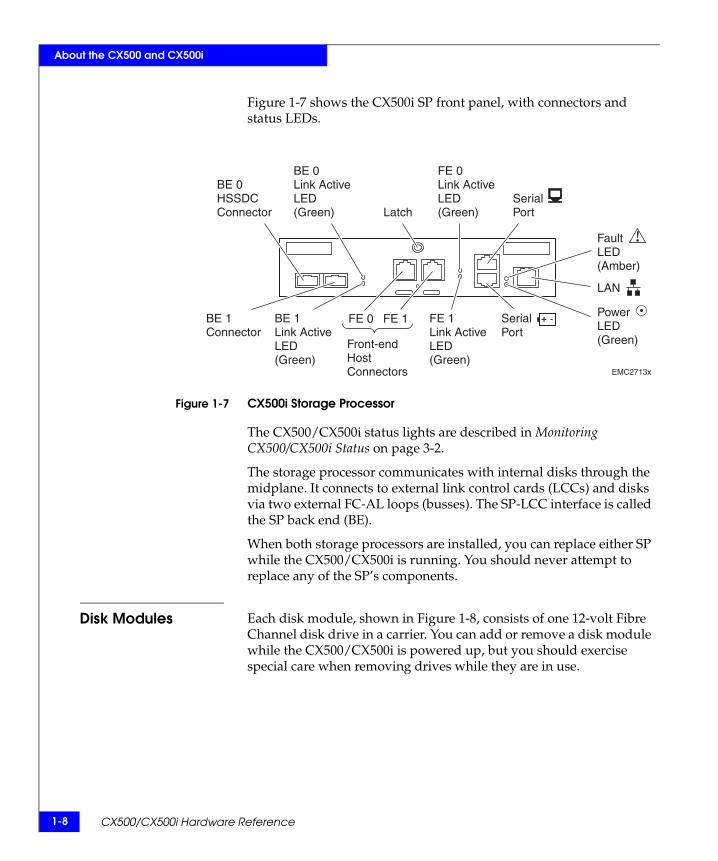
Figure 1-7 shows the CX500i SP front panel, with connectors and status LEDs.
Figure 1-7 CX500i Storage Processor
The CX500/CX500i status lights are described in Monitoring CX500/CX500i Status on page 3-2.
The storage processor communicates with internal disks through the midplane. It connects to external link control cards (LCCs) and disks via two external FC-AL loops (busses). The SP-LCC interface is called the SP back end (BE).
When both storage processors are installed, you can replace either SP while the CX500/CX500i is running. You should never attempt to replace any of the SP’s components.
Disk Modules Each disk module, shown in Figure 1-8, consists of one 12-volt Fibre Channel disk drive in a carrier. You can add or remove a disk module while the CX500/CX500i is powered up, but you should exercise special care when removing drives while they are in use.
FE 0 FE 1
Front-endHostConnectors
PowerLED(Green)
BE 0Link ActiveLED(Green)
BE 1Link ActiveLED(Green)
FE 0Link ActiveLED(Green)
FE 1Link ActiveLED(Green)
BE 0HSSDCConnector
BE 1Connector
Latch
FaultLED(Amber)
LAN
+ -SerialPort
SerialPort
EMC2713x

CX500/CX500i Components 1-9
About the CX500 and CX500i
Drive modules are extremely sensitive electronic components. Refer to the instructions on Handling FRUs and Replacing or Adding a Disk Module in Chapter 3 whenever you handle a disk module.
Figure 1-8 Disk Module
Disk Drives The disk drives are 3.5-inch (8.75 cm) by 1.0-inch (2.54 cm) Fibre Channel drives that conform to the following standards:
SFF-8045 SCSI Enclosure Services (SES) portion of the SCSI 3 Standard FC-AL FC-AL Private Loop Direct Attach (PLDA) Profile 2 Gbit Fibre Channel interface 12 volt only
Drive Carrier The disk drive carrier is a metal and plastic assembly that provides smooth, reliable contact with the enclosure slot guides and midplane connectors. It has a handle with a latch and spring clips. The latch holds the disk module in place to ensure proper connection with the midplane. Disk drive Activity/Fault LEDs are integrated into the carrier.
Power Supply/System Cooling ModulesThe power supply/system cooling (power/cooling) modules are located above the SPs. The units integrate independent power supply and dual-blower cooling assemblies into a single module.
The CX500 and CX500i use a unique power supply/system cooling module that is externally identical to other modules. Do not attempt to use a CX400 or DAE2 power/cooling module in a CX500 or CX500i enclosure.
EMC1758
Carrier
Latch
Handle
DiskDrive

1-10 CX500/CX500i Hardware Reference
About the CX500 and CX500i
Each power supply is an auto-ranging, power-factor-corrected, multi-output, off-line converter with its own line cord. Each supply supports a fully configured DPE2 and shares load currents with the other supply. The drives and SPs have individual soft-start switches that protect the disk drives and SPs if you install them while the disk enclosure is powered up. A FRU (disk, SP, or power/cooling module) with power-related faults will not adversely affect the operation of any other FRU.
The system cooling assembly includes two dual-blower modules. If one blower fails, the others will speed up to compensate. If two blowers in a system (both in one power/cooling module, or one in each module) fail, the CX500/CX500i will go off line within two minutes.
Each power/cooling module has visible status lights (LEDs), as shown inFigure 1-9. (Note that Figure 1-9 shows an ac power supply; LED placement on -48 V dc systems is the same.)The rightmost LED indicates power to the supply; the LED adjacent to it indicates a power supply fault. The leftmost LED indicates a failure in one of the integrated blowers within that module. The status lights are described in Monitoring CX500/CX500i Status on page 3-2.
Figure 1-9 Power Supply/System Cooling Module
Standby Power Supply (SPS)
Disk configurations that use ac source power require standby power supplies (SPS) to prevent data loss during a power failure. The standard CX-Series SPS supports a variety of processor and disk enclosures similar to the CX500/CX500i and DAEs. See Figure 1-10.
EMC2714
acConnector
Latch PowerLED(Green)
Power FaultLED (Amber)
Blower FaultLED(Amber)

CX500/CX500i Components 1-11
About the CX500 and CX500i
Figure 1-10 Standby Power Supply
See Chapter 4, The Standby Power Supply (SPS), for detailed information about SPSs.
Systems with dc power are intended for use in environments with redundant and highly available power sources (for example, "Central Office" grade power within the telecommunications industry), and dc power provided by the site must meet this requirement. The sudden loss of all incoming dc power to a storage system may cause unexpected abnormal behavior of the storage system and loss of write-cache data.
EMC2292
PowerSwitch
SPInterfaceSPE
ActiveLED(Green)
ReplaceBatteryLED(Amber)
On BatteryLED(Amber)
FaultLED(Amber)

1-12 CX500/CX500i Hardware Reference
About the CX500 and CX500i

Installing a CX500/CX500i 2-1
2
This chapter describes the Model CX500 and Model CX500i DPE2 installation requirements and procedures. Major topics include
Requirements......................................................................................2-2 Installing a DPE2 in a Cabinet..........................................................2-5 Setting Up an Installed CX500/CX500i DPE2 ...............................2-7 CX500/CX500i Powerup and Initialization .................................2-21 CX500/CX500i Powerdown ...........................................................2-23
Installing aCX500/CX500i

2-2 CX500/CX500i Hardware Reference
Installing a CX500/CX500i
RequirementsThis section explains site and cabling requirements.
Site Requirements For proper operation, the installation site must conform to certain environmental specifications. These are detailed below and in Appendix A.
Power To determine a CX500/CX500i’s power requirements, use the power rating on the enclosure label. This rating is the maximum power required for a fully loaded enclosure. The input current, power (VA), and dissipation per enclosure are based on the maximum capability of the power supplies and cooling system to provide internally regulated power. Typical values will be less than the maximum, depending on the number and manufacturer of disk drives. These values represent the sum of the values shared by the line cords of two power supplies in the same enclosure. Power cords and supplies share the power load evenly. If one of the two power supplies fails, the remaining supply and cord support the full load. You must use a rackmount cabinet or other mounting standard, with appropriate power distribution, and have main branch ac or dc distribution that can handle these values for the number of components that you will interconnect.
The standard 40U EMC cabinet includes two 240-volt ac power cables and independent power distribution units (PDUs). To support all of the CX500/CX500i system’s high-availability features, you must connect each power outlet to a different circuit.
Storage systems with -48 V dc power supplies also require separate circuits for each supply to maintain high availability.
Cooling The temperature at the front bezel inlet must meet the ambient temperature specification described in Appendix A. The site must have air conditioning that can maintain the specified ambient temperature range. The air conditioning must be able to support the BTU requirements of the CX500/CX500i DPE2 and any additional disk enclosures.
Cabling Requirements
CX500 and CX500i DPE2s support copper cable for back-end (BE) connections to disks they control (for example, DAE disk enclosures). The CX500 uses optical cables for front-end (FE) connections to the

Requirements 2-3
Installing a CX500/CX500i
external Fibre Channel environment; CX500i systems use standard category 5 or category 6 LAN cables for front-end connections to the external Ethernet environment.
Any copper back-end cables you use must meet the appropriate standards for 2-Gbit FC-AL. Such cables must be fully shielded, twin-axial, full-duplex cables with high speed serial data connector (HSSDC) connectors. Distances greater than 1 meter require equalized cables; unequalized 1-meter cables are adequate. The DPE2 does not support cables shorter than 1 meter or longer than 10 meters.
EMC supports and can provide 1-, 5-, and 10-meter cables. The 5- and 10-meter cables are equalized.
Interconnections between the CX500/CX500i and disk enclosures should maintain consistency with the link controller cards (LCCs) in the additional disk enclosures. For example, in a two-loop (two-bus) configuration, one pair of Fibre Channel (FC) loops should interconnect SP A to all the LCC As, and the other Fibre Channel pair of loops should interconnect SP B with all (and only) LCC Bs.
Do not leave an unused (that is dangling) cable connected to a host or enclosure port because it may cause excess noise on the loop.
Addressing Requirements
The CX500/CX500i SPs process front-end I/O from servers (hosts), and back-end communication between disks and the enclosures that contain them. Each host bus adapter, storage processor, and disk requires a unique identifier, or address.
Front-end (FE) addressing requirements vary depending on the environment.
• Fibre Channel fabric (sometimes called fibre port) configurations include a Fibre Channel switch between the storage system and host bus adapters on connected servers. Fibre loop (FC-AL) front ends connect directly to a server.
In a fabric environment, the switch assigns a unique fabric ID to each host bus adapter (HBA) and storage processor. In direct-attach configurations, the HBA and SP negotiate a default arbitrated loop physical address (ALPA).
• iSCSI front-end addresses are internet protocol (IP) addresses that you manually assign when you configure the iSCSI ports with the Navisphere Storage System Initialization Utility.

2-4 CX500/CX500i Hardware Reference
Installing a CX500/CX500i
The CX500 and CX500i back end (BE) addresses each DPE2 and DAE using the FC-AL address (loop) identification and the DAE enclosure address (EA). You determine both the loop ID (sometimes called a bus ID) and the enclosure address during the hardware setup. Loop IDs (0, 1) correspond to the BE port numbers on the CX500/CX500i SP.
Enclosure Address(EA)
Each CX500/CX500i DPE2 and DAE on a back-end loop needs a unique enclosure address (EA), 0-3, that identifies the enclosure and determines the disk ALPA addresses. Valid enclosure addresses for CX500-Series systems are 0, 1, 2, and 3.
The CX500/CX500i DPE2 has a fixed EA of 0, which you should not change. The CX500/CX500i supports two loops and a maximum of four disk enclosures per Fibre Channel loop. For ease of use, we recommend that you keep the EAs sequential and that the loops correspond to each other; a maximum configuration would therefore include an EA 0, EA 1, EA 2 and an EA 3 for each loop. You specify enclosure addresses with a switch on each DPE2 and DAE.
Disk Requirements CX500/CX500i storage systems require at least five disk modules installed in slots 0, 1, 2, 3 and 4 (the leftmost slots) of the enclosure. Disk module IDs are numbered left to right (facing the unit) and are contiguous throughout a storage system: enclosure 0 contains modules 0-14; enclosure 1 contains modules 15-29, and so on.
The disk modules in slots 0-4 provide recovery and mirrored boot capability and are preloaded according to their slot assignment before shipment. Do not move a preloaded module from its assigned slot to another slot. Remove it only to replace the disk.
For details on DAE disks and their configuration, refer to the Hardware Reference for your disk-array enclosure.

Installing a DPE2 in a Cabinet 2-5
Installing a CX500/CX500i
Installing a DPE2 in a CabinetThe CX500/CX500i mounts inside a cabinet or rack on two L-shaped mounting rails connected to the cabinet’s vertical channels.
How to install the cabinet or rack is explained in the cabinet installation manual that shipped with the unit.
How to install the universal mounting rails in the cabinet, and the 3U chassis on those rails, is explained in the EMC Rails and Enclosures (CX-Series Storage Systems) Field Installation Guide available on the EMC Powerlink website.
Warnings and Recommendations
The cabinet or rack in which you will install the CX500/CX500i must have a full earth ground to provide reliable grounding. Also, the cabinet/rack should have its own switchable power distribution. We suggest that you use a cabinet/rack that has dual power distribution units, one on each side.
WARNING
The enclosure is heavy and should be installed into a rack by two people. To avoid personal injury and/or damage to the equipment, do not attempt to lift and install the enclosure into a rack without a mechanical lift and/or help from another person.
L’armoire étant lourde, sa mise en place sur une rampe nécessite deux personnes. Afin de ne pas vous blesser et/ou endommager le matériel, n’essayez pas de soulever et d’installer l’armoire sur une rampe sans avoir recours à un relevage mécanique et/ou à l’aide d’une autre personne.
Das Gehäuse ist schwer und sollte nur von zwei Personen in einem Rack installiert werden. Zur Vermeidung von körperlichen Verletzungen und/oder der Beschädigung des Gerätes, bitte das Gehäuse nicht ohne die Hilfe einer zweiten Person anheben und einbauen.
Il contenitore è pesante e dev'essere installato nel rack da due persone. Per evitare danni personali e/o all’apparecchiatura, non tentare di sollevare ed installare in un rack il contenitore senza un sollevatore meccanico e/o l’aiuto di un’altra persona.
2-6 CX500/CX500i Hardware Reference
Installing a CX500/CX500i
Debido a su considerable peso, la instalación del compartimento en el bastidor deben realizarla siempre dos personas. Para evitar daños personales o en el equipo, el compartimento no debe levantarse ni instalarse en el bastidor sin la ayuda de un elevador mecánico o de otra persona.
We recommend that you use cabinet anti-tip devices, especially if you are installing or removing a CX500/CX500i or DAE in the upper half of the cabinet when the lower half is empty.

Setting Up an Installed CX500/CX500i DPE2 2-7
Installing a CX500/CX500i
Setting Up an Installed CX500/CX500i DPE2
CAUTION!Be sure the standby power supplies and circuit breakers in your cabinet are switched off before you begin setting up the CX500/CX500i.
Setting Enclosure Addresses
Each disk enclosure in your system must have a unique enclosure address (EA, sometimes called an enclosure ID) that together with the loop ID identifies the enclosure and determines disk module IDs. In most cases, the enclosure address has been set before shipment to coincide with the rest of the system; you need to reset the address if you installed the enclosure into your cabinet/rack independently. The EA can range from 0 through 3; we recommend that you number them consecutively from 0. The CX500/CX500i is always enclosure 0. Additional DAE disk enclosures are numbered 0, 1, 2 or 3, depending on their position on the Fibre Channel loop (bus) connecting the storage system. You set the EA with the enclosure address switch. DPE2 and DAE2 EA switches have one push button for incrementing the address and another for decrementing it; DAE2Ps have a single push button that increments in an address loop. Use a pen, paper clip, or small screwdriver to set the EA as follows:
CAUTION!DPE2 or DAE2 drives read their FC-AL physical address only at powerup or when the drive is reset. To avoid losing access to data, you must set the EA in those enclosures when power is off; you cannot change the EA while power is on.
Set and read the EA for DAE2P enclosures when power is on. Refer to your DAE2P setup guide or hardware reference for instructions on changing a DAE2P enclosure address.

2-8 CX500/CX500i Hardware Reference
Installing a CX500/CX500i
1. Make sure the enclosure address for the CX500/CX500i is set to 0. Refer to Figure 2-1.
2. Set the enclosure address for any additional disk enclosures.
• Set the first DAE on Loop 0 (BE 0) to EA 1.
• Set the first DAE on Loop 1 (BE 1)to EA 0, and the second to EA 1.
• Set the EA on subsequent DAEs sequentially depending on the loop to which they connect; EA 2 on loop 0, EA 2 on loop 1, and so on.
Set EAs for DAE2P disk enclosures after the system is powered on.
See Figure 2-1 and Figure 2-8 as necessary.
Figure 2-1 CX500-Series Enclosure Address Switch
Making Power Connections - ac Power Source
Follow these instructions to make power connections for CX500-Series systems with ac power supplies.
Note that the CX500/CX500i ac power supplies use retention bails to relieve strain on the power cords and to keep the cords seated in their connectors.
Refer to Figure 2-2 as you connect the ac line cord to the power supplies.
1. Plug an ac line cord into each power supply/cooling module.
EMC2712
EnclosureAddressSwitch+
_
0

Setting Up an Installed CX500/CX500i DPE2 2-9
Installing a CX500/CX500i
2. Release the retention bail from its slot on the power/cooling module, and push the loop of the bail over the power cord to hold the cord in position.
Figure 2-2 ac Line Cord and the Retention Bails
3. Plug the other end of the CX500/CX500i power cords into the standby power supply that corresponds to each power supply/cooling module (PS); for example, PS A to SPS A, PS B to SPS B. Refer to Figure 2-3.
Figure 2-3 Connecting CX500/CX500i Power Cords to the Standby Power Supplies
EMC2715
acConnector and Bail
acConnector and Bail
EMC2716
SPS A
PowerSupply A(PS A)
PowerSupply B(PS B)
SPS B
2-10 CX500/CX500i Hardware Reference
Installing a CX500/CX500i
Make certain you secure the power cords with the retention bails (strain reliefs) at each connector. The bails prevent the power cord from pulling out of the connections.
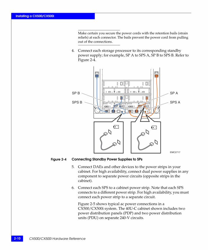
4. Connect each storage processor to its corresponding standby power supply; for example, SP A to SPS A, SP B to SPS B. Refer to Figure 2-4.
Figure 2-4 Connecting Standby Power Supplies to SPs
5. Connect DAEs and other devices to the power strips in your cabinet. For high availability, connect dual power supplies in any component to separate power circuits (opposite strips in the cabinet).
6. Connect each SPS to a cabinet power strip. Note that each SPS connects to a different power strip. For high availability, you must connect each power strip to a separate circuit.
Figure 2-5 shows typical ac power connections in a CX500/CX500i system. The 40U-C cabinet shown includes two power distribution panels (PDP) and two power distribution units (PDU) on separate 240-V circuits.
EMC2717
+ -+ -
SP ASP B
SPS ASPS B

Setting Up an Installed CX500/CX500i DPE2 2-11
Installing a CX500/CX500i
Figure 2-5 CX500/CX500i Power Connections
Making Power Connections - dc Power Source
Follow these instructions to make power connections for CX500 systems with dc power supplies.
1. Connect RJ45-RJ12 sense cables (sometimes called SPS emulator cables) between each power supply and the SPS serial connector on its corresponding storage processor, as shown in Figure 2-6 on page 2-12.
!!
!!
!
EXP PRI
EXP PRI
#
!
EXPPRI
EXPPRI
#A
B
!!
!!
!
EXP PRI
EXP PRI
#
!
EXPPRI
EXPPRI
#A
B
!!
!!
!
EXP PRI
EXP PRI
#
!
EXPPRI
EXPPRI
#A
B
SP B SP A
DAE
DAE
DAE
ONI
OFFO
ONI
OFFO
ONI
OFFO
ONI
OFFO
ONI
OFFO
ONI
OFFO
EMC3207
SPS B SPS A
240 V 240 V
Power/CoolingModule B
Power/CoolingModule A
MasterSwitch
PowerCord
SPS + -
2-12 CX500/CX500i Hardware Reference
Installing a CX500/CX500i
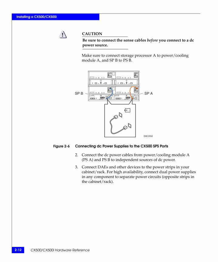
CAUTION!Be sure to connect the sense cables before you connect to a dc power source.
Make sure to connect storage processor A to power/cooling module A, and SP B to PS B.
Figure 2-6 Connecting dc Power Supplies to the CX500 SPS Ports
2. Connect the dc power cables from power/cooling module A (PS A) and PS B to independent sources of dc power.
3. Connect DAEs and other devices to the power strips in your cabinet/rack. For high availability, connect dual power supplies in any component to separate power circuits (opposite strips in the cabinet/rack).
+ -
EMC2959
SP ASP B

Setting Up an Installed CX500/CX500i DPE2 2-13
Installing a CX500/CX500i
Making Back-End Connections
CAUTION!Before making any new back-end connections to or between DAEs, verify your enclosure addresses as follows:
• Make sure the EA switch on each DAE2 indicates the correct enclosure address.
• Power up any DAE2Ps before cabling to the PRI or EXP connectors. If the enclosure address LEDs indicate an incorrect or invalid EA, reset the address to the correct value.
The CX500/CX500i supports two redundant Fibre Channel back-end loops on each SP for a total of four independent loops. Loop 0 from SP A and loop 0 from SP B are paired, and share access to the same dual-port disk drives. Loops starting at the BE 1 connectors are also paired and share disks in the same way. Together, loops A0/B0 and A1/B1 act as two redundant loops, also called buses.
Cable your back-end loops as follows:
1. Attach copper cables from the CX500/CX500i DPE2 to additional disk enclosures, as shown in Figure 2-7 and Figure 2-8.
Figure 2-7 Connecting a CX500/CX500i DPE2 to Another Disk Enclosure
EMC2719
To DAE
BE 0Connector

2-14 CX500/CX500i Hardware Reference
Installing a CX500/CX500i
2. Connect BE 0 on each CX500/CX500i SP to the corresponding Primary (PRI) connector in the first additional disk enclosure (EA 1) in Loop 0.
3. Connect BE 1 on each SP to the first corresponding PRI connectors in Loop 1 (EA 0).
4. Cable the remaining disk enclosures together as shown in Figure 2-8.
The example configurations that follow show a CX500 below seven DAE disk-array enclosures. The eight devices support two completely redundant (four total) loops. Note that the DPE2 connects to the Primary disk enclosure connectors, and subsequent enclosures connect in an Expansion-to-Primary chain.
You can mix DAE2 and DAE2P enclosures in a storage system and along a loop.

Setting Up an Installed CX500/CX500i DPE2 2-15
Installing a CX500/CX500i
Figure 2-8 Cabling CX500/CX500i and DAE2 Disk-Array Enclosures Together
EXP EXPPRI PRI
EA1/Loop 1
EA0/Loop 1
EA0/Loop 0
Loop 0 Loop 0
Loop 1
Loop 0
Loop 1
Loop 0
Loop 1
Loop 1
Loop 0
Loop 1
Loop 0
Loop 1
Loop 1 Loop 1
EA1/Loop 0
EA2/Loop 1
EA2/Loop 0
EA3/Loop 1
EA3/Loop 0
LCC B LCC A
BE 1 BE 1
BE 0BE 0
EMC2720

2-16 CX500/CX500i Hardware Reference
Installing a CX500/CX500i
Figure 2-9 Cabling CX500/CX500i and DAE2P Disk-Array Enclosures Together
!!
!!
!
EXP PRI
EXP PRI
#
!
EXPPRI
EXPPRI
#A
B
!!
!!
!
EXP PRI
EXP PRI
#!
EXPPRI
EXPPRI
#A
B
!!
!!
!
EXP PRI
EXP PRI
#
!
EXPPRI
EXPPRI
#A
B
!!
!!
!
EXP PRI
EXP PRI
#
!
EXPPRI
EXPPRI
#A
B
EA0/Loop 0
!!
!!
!
EXP PRI
EXP PRI
#
!
EXPPRI
EXPPRI
#A
B
EA1/Loop 0
!!
!!
!
EXP PRI
EXP PRI
#
!
EXPPRI
EXPPRI
#A
B
EA2/Loop 0
!!
!!
!
EXP PRI
EXP PRI
#
!
EXPPRI
EXPPRI
#A
B
EA3/Loop 0
BE 1BE 1
PRI
EA1/Loop 1
EA0/Loop 1
EXP
PRI EXP
EA2/Loop 1
EA3/Loop 1
BE 0BE 0
EMC3225
Loop 0 Loop 0
Loop 1
Loop 0
Loop 1
Loop 0
Loop 1
Loop 1
Loop 0
Loop 1
Loop 0
Loop 1
Loop 1 Loop 1

Setting Up an Installed CX500/CX500i DPE2 2-17
Installing a CX500/CX500i
Connecting the CX500 to the External EnvironmentThis section describes how to connect a Fibre Channel front end to its external environment (switches or direct attachment to a server). If you are installing a CX500i (iSCSI front end) system, skip this section and continue with Connecting the CX500i to the External Environment on page 2-19.
When working with optical cables, observe the following precautions:
Keep the covers on all optical cables and optical connectors until you are ready to insert the cables. The covers protect the cables and connectors, and prevent foreign particles, such as dust, from entering and affecting the connection.
Do not leave any unused (dangling) cables connected to an SP port.
Avoid tight bends. If you need to make a 90º bend, do it over 6 to 12 inches.
Do not use optical cables to support weight, including long cable runs without support.
Do not pull long runs of cable. It is best to lay the cable in place or pull only a few feet at a time.
Run the cables so that they are not stepped on or rolled over by anything.
Follow the steps below to cable the SPs and connect them to the external environment:
1. Remove the protective covers from each optical connector and each optical cable, as shown in Figure 2-10.
2. Plug the cable into a host port on the SP. See Figure 2-10.

2-18 CX500/CX500i Hardware Reference
Installing a CX500/CX500i
Figure 2-10 Attaching Fibre-Optic (Front-End) Cables to the SP
3. For each SP connection to the external environment, attach an optical cable from the front-end (FE) port to the external environment.
a. For the FE 0 host port, plug the other end of the fibre-optic cable into the Host Bus Adapter (HBA) or switch port.
b. For the FE 1 host port on a storage system without MirrorView™ software, plug the other end of the cable into the HBA or switch port.
For the FE 1 host port on a storage system with MirrorView, plug the other end of the cable into the corresponding storage processor (SP) host port on the remote storage system, or into the switch port zoned to the corresponding SP.
EMC2721

Setting Up an Installed CX500/CX500i DPE2 2-19
Installing a CX500/CX500i
Connecting the CX500i to the External EnvironmentThis section describes how to connect an iSCSI front end to its external environment (switches or direct attachment to a server). If you are installing a CX500 (Fibre Channel front end) system, go to on page 2-16.
All iSCSI data port (front end) connections must be 1-gigabit LAN, even if the server NIC connection is 10/100; the CX500i supports 10/100 LAN connection to the management port only.
Data and host ports that are not physically connected together (directly or through a switch) must be on separate subnetworks. In direct-connect configurations, every data port must be on a separate subnet, and another subnet is required for the management ports.
Connect the storage system iSCSI data ports to the gigabit Ethernet network as follows:
1. Plug Ethernet cables into the two front-end iSCSI ports on each SP (FE 0 and FE 1). See Figure 2-11.
Figure 2-11 Connecting a Gigabit Ethernet Cable
EMC recommends category six (CAT 6) cables for the 1-gigabit Ethernet connection; CAT 5E and CAT 5 cables are supported.
EMC3037
Ethernet Cable
2-20 CX500/CX500i Hardware Reference
Installing a CX500/CX500i
2. Connect the free end of the data port cables to gigabit Ethernet ports as follows:
• For a storage area network (SAN) configuration, connect the cables to gigabit Ethernet ports on network devices such as switches or routers.
• For a direct attach configuration, connect the cables to the iSCSI initiator ports (gigabit Ethernet NICs or iSCSI HBAs). If the NICs or HBAs are not yet installed in the initiators, install them as described in the device-specific documentation.
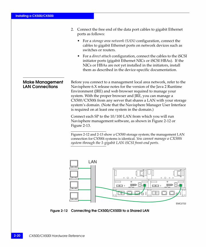
Make Management LAN Connections
Before you connect to a management local area network, refer to the Navisphere 6.X release notes for the version of the Java 2 Runtime Environment (JRE) and web browser required to manage your system. With the proper browser and JRE, you can manage a CX500/CX500i from any server that shares a LAN with your storage system’s domain. (Note that the Navisphere Manager User Interface is required on at least one system in the domain.)
Connect each SP to the 10/100 LAN from which you will run Navisphere management software, as shown in Figure 2-12 or Figure 2-13.
Figures 2-12 and 2-13 show a CX500 storage system; the management LAN connection for CX500i systems is identical. You cannot manage a CX500i system through the 1-gigabit LAN iSCSI front-end ports.
Figure 2-12 Connecting the CX500/CX500i to a Shared LAN
EMC2722
LAN

CX500/CX500i Powerup and Initialization 2-21
Installing a CX500/CX500i
Figure 2-13 Connecting the CX500/CX500i to a Local Management Client
CX500/CX500i Powerup and InitializationBefore applying power to a storage system, make sure all the disk module slots in each disk enclosure contain either disk or filler modules, for proper cooling and normal operation.
Do not power up a disk enclosure without at least one SP or LCC installed.
Power up the CX500/CX500i as follows:
1. Connect power to all DAEs connected to the CX500/CX500i. If any of the DAEs have power switches, turn them to the on position.
2. If present, turn the CX500/CX500i’s power/cooling module switches to the on (l) position.
3. If present, turn the SPS power switches to the on position.
4. In the cabinet/rack, set the master switches (main circuit breaker switches on some older cabinets) to the on position.
The CX500/CX500i and any DAEs in the cabinet/rack will power up.
EMC2723
Hub

2-22 CX500/CX500i Hardware Reference
Installing a CX500/CX500i
The only power switches on most ac CX500/CX500i and DAE disk enclosures are those on the standby power supply and the cabinet circuit breakers, which are normally on. (Power switches on those power/cooling modules that include them are usually in the on position as well.) As a result, the units are always active.
When you initially apply power to a disk enclosure, the disk drives power up according to their specifications, and spin up in a specified sequence dictated by enclosure and loop ID. The slot spin-up delays range from 0 to 84 seconds. The slots use the same delays when you insert a drive while the system is powered up.
The CX500/CX500i hardware monitor (FRU monitor) resets and begins its control loop. The port bypass circuits enter the states indicated by their associated drives. The monitor continues to run in this local mode until it receives commands that dictate otherwise. In local mode, the monitor maintains the port bypass circuits in the same states as the drive command signals. When a drive fault occurs, the corresponding drive fault light turns on. Firmware commands can take control of the port bypass circuits and the drive status lights.
CAUTION!DPE2 or DAE2 drives read their FC-AL physical address only at powerup or when the drive is reset. To avoid losing access to data, you must set the EA in those enclosures when power is off; you cannot change the EA while power is on.
Set and read the EA for DAE2P enclosures when power is on. Refer to your DAE2P setup guide or hardware reference for instructions on changing a DAE2P enclosure address.
For instructions on how to initialize your system after its first powerup, refer to the CX500 Setup Guide or the CX500i Setup Guide, and the EMC Installation Roadmap for CX-Series, AX-Series, and FC-Series Storage Systems.
CX500/CX500i Powerdown 2-23
Installing a CX500/CX500i
CX500/CX500i PowerdownCX500/CX500i storage systems with ac power require an SPS. If a properly configured ac system is powered down abnormally (for example, a brownout or ac/dc failure), cached data is saved to the storage-system vault disks. However, when the CX500/CX500i is powered back up, it may take longer to come on line.
Turning Off the Power - ac Systems
Follow these instructions to power down CX500-Series storage systems with ac power. For instructions on powering down dc-powered storage systems, go to Turning Off the Power - dc Systems on page 2-24.
1. Stop all I/O activity to the CX500/CX500i.
Stopping the I/O allows the SP to destage cache data, and may take some time. The length of time will be based on criteria such as the size of cache, the amount of data in the cache, the type of data in the cache, and the target location on the disks, but it is typically less than one minute.
2. If the server connected to the CX500/CX500i is running the UNIX® operating system, unmount file systems.
3. Use the power switch on each SPS to turn off power to the CX500/CX500i DPE2 and any other device connected to the SPS. See Figure 2-14.
You do not need to shut off or disconnect power from any of the connected DAEs.
CAUTION!Never disconnect the ac power supply/cooling modules to shut down a CX500/CX500i. Bypassing the SPS in that manner prevents the system from saving write cache data to the vault drives, and results in data loss. You will lose access to data, and the storage processor event log will display an error message similar to the following:Enclosure 0 Disk 5 0x90a (Can’t Assign - Cache Dirty) 0
0xafb40 0x14362c.
Contact your service provider if this situation occurs.

2-24 CX500/CX500i Hardware Reference
Installing a CX500/CX500i
Figure 2-14 Powering Down a CX500 System with SPS (ac Power)
Turning Off the Power - dc Systems
Follow these instructions to power down CX500 storage systems with dc power. For instructions on powering down ac-powered storage systems, go to Turning Off the Power - ac Systems on page 2-23.
1. Stop all I/O activity to the CX500/CX500i.
Stopping the I/O allows the SP to destage cache data, and may take some time. The length of time will be based on criteria such as the amount of cache, the amount of data in the cache, the type of data in the cache, and the target location on the disks, but it is typically less than one minute.
EMC2724
DAE2
DAE2
DAE2
SP B SP A
CircuitBreaker
CircuitBreaker
PowerSwitch/CordDAE2 Power
Switch/CordDAE2
Power/CoolingModule A
Power/CoolingModule B
Power SwitchSPS B
Power SwitchSPS A
CX500/CX500i Powerdown 2-25
Installing a CX500/CX500i
2. If the server connected to the CX500 is running the UNIX® operating system, unmount file systems.
3. On the DPE2, toggle each power supply’s on/off switch to the Off position.
Allow the power supply to complete its shutdown sequence before removing the power source. An orderly shutdown that flushes all cache can take up to several seconds before the host sends a “STOP” to the power supply.
4. Power off the power strips A and B.
If you need to retain power to other systems in a rack/cabinet, leave the power strips powered on. You can either toggle the DAE power switches (if present) to the off position, or remove the DAE power cords.

2-26 CX500/CX500i Hardware Reference
Installing a CX500/CX500i

Servicing and Upgrading a CX500 or CX500i 3-1
3
This chapter describes how to monitor CX500/CX500i status, handle field-replaceable units (FRUs), and replace or add a FRU. Topics are
Monitoring CX500/CX500i Status...................................................3-2 Handling FRUs...................................................................................3-5 Replacing or Adding a Disk Module ..............................................3-9 Replacing a Storage Processor (SP) ...............................................3-16 Replacing a Power Supply/System Cooling Module.................3-18
Servicing andUpgrading a CX500 or
CX500i
3-2 CX500/CX500i Hardware Reference
Servicing and Upgrading a CX500 or CX500i
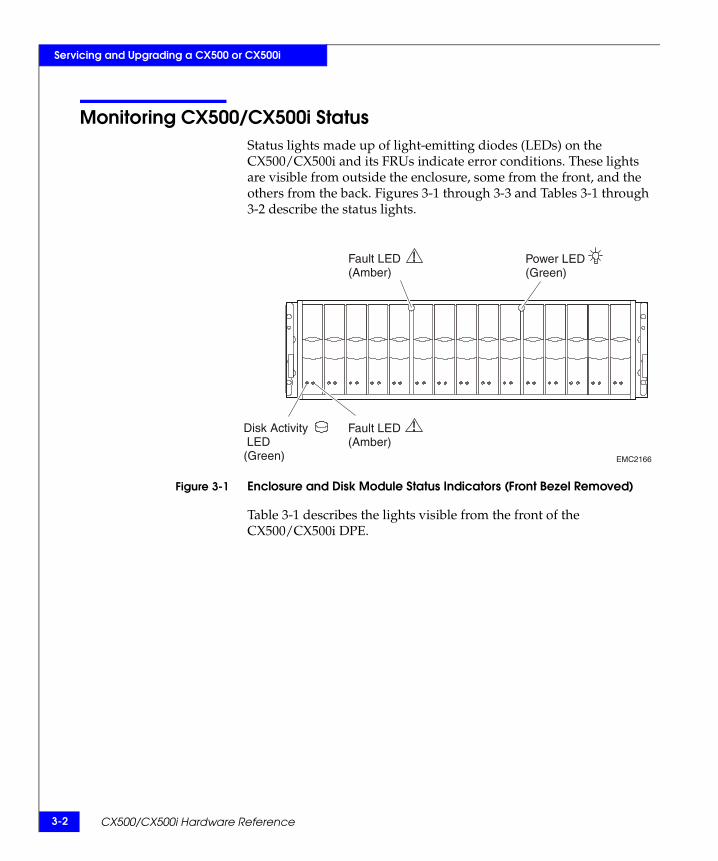
Monitoring CX500/CX500i StatusStatus lights made up of light-emitting diodes (LEDs) on the CX500/CX500i and its FRUs indicate error conditions. These lights are visible from outside the enclosure, some from the front, and the others from the back. Figures 3-1 through 3-3 and Tables 3-1 through 3-2 describe the status lights.
Figure 3-1 Enclosure and Disk Module Status Indicators (Front Bezel Removed)
Table 3-1 describes the lights visible from the front of the CX500/CX500i DPE.
EMC2166
Power LED(Green)
Fault LED(Amber)
Fault LED(Amber)
Disk Activity LED(Green)
Monitoring CX500/CX500i Status 3-3
Servicing and Upgrading a CX500 or CX500i
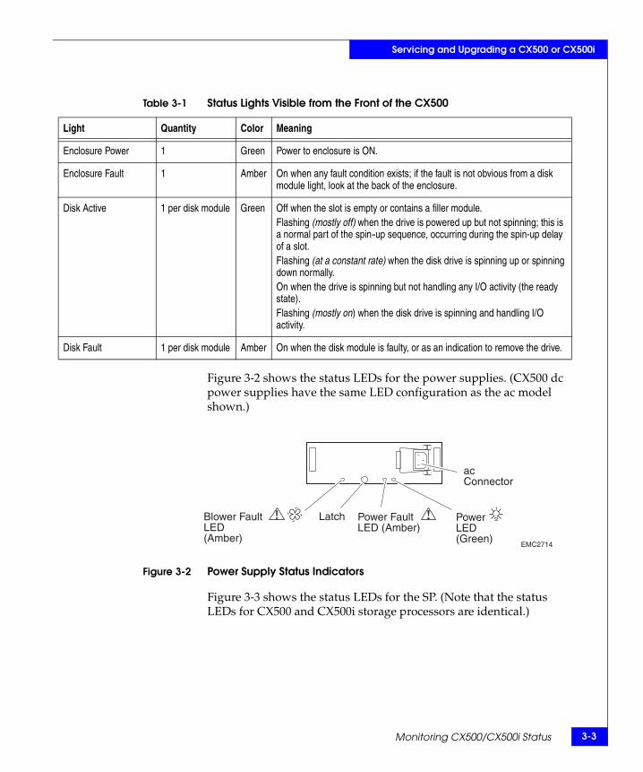
Figure 3-2 shows the status LEDs for the power supplies. (CX500 dc power supplies have the same LED configuration as the ac model shown.)
Figure 3-2 Power Supply Status Indicators
Figure 3-3 shows the status LEDs for the SP. (Note that the status LEDs for CX500 and CX500i storage processors are identical.)
Table 3-1 Status Lights Visible from the Front of the CX500
Light Quantity Color Meaning
Enclosure Power 1 Green Power to enclosure is ON.
Enclosure Fault 1 Amber On when any fault condition exists; if the fault is not obvious from a disk module light, look at the back of the enclosure.
Disk Active 1 per disk module Green Off when the slot is empty or contains a filler module.Flashing (mostly off) when the drive is powered up but not spinning; this is a normal part of the spin-up sequence, occurring during the spin-up delay of a slot.Flashing (at a constant rate) when the disk drive is spinning up or spinning down normally.On when the drive is spinning but not handling any I/O activity (the ready state).Flashing (mostly on) when the disk drive is spinning and handling I/O activity.
Disk Fault 1 per disk module Amber On when the disk module is faulty, or as an indication to remove the drive.
EMC2714
acConnector
Latch PowerLED(Green)
Power FaultLED (Amber)
Blower FaultLED(Amber)

3-4 CX500/CX500i Hardware Reference
Servicing and Upgrading a CX500 or CX500i
Figure 3-3 SP Status Indicators (CX500 Shown)
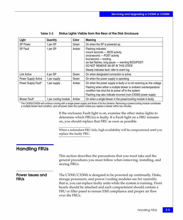
Table 3-2 describes the status LEDs visible from the rear of the disk enclosure.
PowerLED(Green)
BE 0Link ActiveLED(Green)
BE 1Link ActiveLED(Green)
FE 0Link ActiveLED(Green)
FE 1Link ActiveLED(Green)
FaultLED(Amber)
EMC2726
Handling FRUs 3-5
Servicing and Upgrading a CX500 or CX500i
If the enclosure Fault light is on, examine the other status lights to determine which FRU(s) is faulty. If a Fault light on a FRU remains on, you should replace that FRU as soon as possible.
When a redundant FRU fails, high availability will be compromised until you replace the faulty FRU.
Handling FRUsThis section describes the precautions that you must take and the general procedures you must follow when removing, installing, and storing FRUs.
Power Issues and FRUs
The CX500/CX500i is designed to be powered up continually. Disks, storage processors, and power/cooling modules are hot repairable; that is, you can replace faulty units while the system is running. Front bezels should be attached and each compartment should contain a FRU or filler panel to ensure EMI compliance and proper air flow over the FRUs.
Table 3-2 Status Lights Visible from the Rear of the Disk Enclosure
Light Quantity Color MeaningSP Power 1 per SP Green On when the SP is powered up.
SP Fault 1 per SP Amber Flashing indicates: once/4 seconds — BIOS activity.once/second — POST activity.four/second — booting.six fast flashes, long pause — rewriting BIOS/POST: DO NOT REMOVE AN SP IN THIS STATESteady indicates fault; refer to event log.
Link Active 4 per SP Green On when designated connection is active.Power Supply Active 1 per supply Green On when the power supply is operating.Power Supply Fault* 1 per supply Amber On when the power supply is faulty or is not receiving ac line voltage
Flashing when either a multiple blower or ambient overtemperature condition has shut the dc power off to the system. Flashing may also indicate incorrect (non-CX500) power supply
Blower Fault* 1 per cooling module Amber On when a single blower in the power/cooling module is faulty.* The CX500/CX500i will continue running with a single power supply and three of its four blowers. Removing a power/cooling module constitutes
a multiple blower fault condition, and will power down the system unless you replace a blower within two minutes.
3-6 CX500/CX500i Hardware Reference
Servicing and Upgrading a CX500 or CX500i
While the CX500/CX500i is powered up, you can service or replace any FRU, although removing an active SP will affect operating-system access to the disks it controls. You should not remove a faulty FRU until you have a replacement available.
Since you can replace or add any FRU without sliding the enclosure out of the cabinet, you do not have to use cabinet anti-tip devices when you upgrade or service a CX500.
If you need to power down a CX500, first stop I/O to the storage processors. For systems using ac power, shut off power to each SPS. To turn off storage systems with dc power, use the On/Off toggle switch on dc power/cooling modules. You do not need to shut down main power lines to the disk enclosure unless you need to power down all the cabinet/rack contents connected to that line. (Refer to CX500/CX500i Powerdown on page 2-23 for more detail.)
CAUTION!Never shut off or disconnect an SPS- connected power/cooling module to shut down a CX500/CX500i. Bypassing the SPS in that manner prevents the system from saving write cache data to the vault drives, and results in data loss. You lose access to data, and the storage processor event log displays an error message similar to the following:
Enclosure 0 Disk 5 0x90a (Can’t Assign - Cache Dirty) 0
0xafb40 0x14362c.
Contact your service provider if this situation occurs.
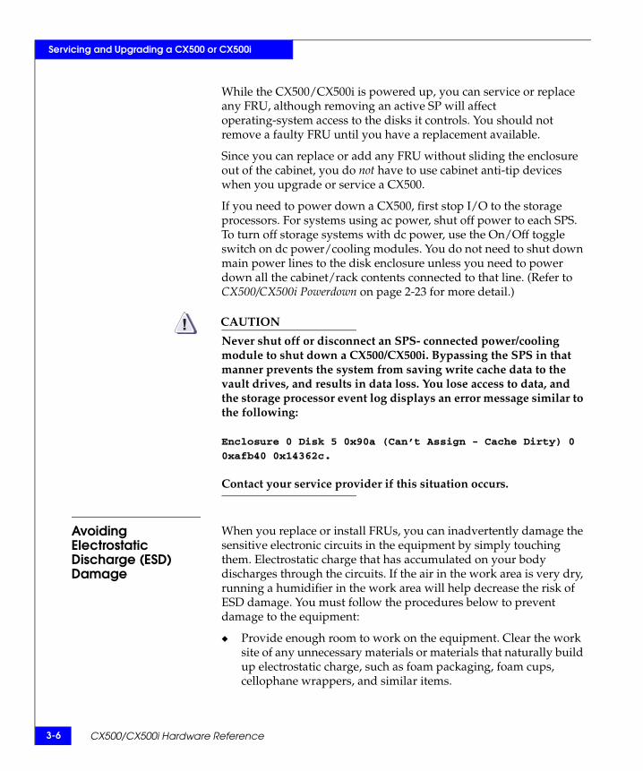
Avoiding Electrostatic Discharge (ESD) Damage
When you replace or install FRUs, you can inadvertently damage the sensitive electronic circuits in the equipment by simply touching them. Electrostatic charge that has accumulated on your body discharges through the circuits. If the air in the work area is very dry, running a humidifier in the work area will help decrease the risk of ESD damage. You must follow the procedures below to prevent damage to the equipment:
Provide enough room to work on the equipment. Clear the work site of any unnecessary materials or materials that naturally build up electrostatic charge, such as foam packaging, foam cups, cellophane wrappers, and similar items.

Handling FRUs 3-7
Servicing and Upgrading a CX500 or CX500i
Do not remove replacement or upgrade FRUs from their antistatic packaging until you are ready to install them.
Gather together the ESD kit and all other materials you will need before you service an enclosure. Once servicing begins, you should avoid moving away from the work site; otherwise, you may build up an electrostatic charge.
Use the ESD kit when handling any FRU. If an emergency arises and the ESD kit is not available, follow the procedures in the Emergency Procedures (Without an ESD Kit) section.
An ESD wristband is supplied with your storage system. To use it, attach the clip of the ESD wristband (strap) to any bare (unpainted) metal on the enclosure; then put the wristband around your wrist with the metal button against your skin.
Emergency Procedures (Without an ESD Kit)
In an emergency when an ESD kit is not available, use the following procedures to reduce the possibility of an electrostatic discharge by ensuring that your body and the subassembly are at the same electrostatic potential.
These procedures are not a substitute for the use of an ESD kit. Follow them only in the event of an emergency.
Before touching any FRU, touch a bare (unpainted) metal surface of the cabinet or enclosure.
Before removing any FRU from its antistatic bag, place one hand firmly on a bare metal surface of the enclosure, and at the same time, pick up the FRU while it is still sealed in the antistatic bag. Once you have done this, do not move around the room or contact other furnishings, personnel, or surfaces until you have installed the FRU.
When you remove a FRU from the antistatic bag, avoid touching any electronic components and circuits on it.
If you must move around the room or touch other surfaces before installing a FRU, first place the FRU back in the antistatic bag. When you are ready again to install the FRU, repeat these procedures.

3-8 CX500/CX500i Hardware Reference
Servicing and Upgrading a CX500 or CX500i
Precautions When Removing, Installing, or Storing FRUs
Use the precautions listed below when you remove, handle, or store FRUs.
Do not remove a faulty FRU until you have a replacement available.
Handle a FRU only when using an ESD wristband as follows:
1. attach the clip of the ESD wristband to the ESD bracket or bare metal on the enclosure
2. then put the wristband around your wrist with the metal button against your skin.
Handle FRUs gently. A sudden jar, drop, or vibration can permanently damage a FRU and may not be immediately evident. Never place a FRU on a hard surface such as an unpadded cart, floor, or desktop, or stacked on top of another FRU.
Never use excessive force to remove or install a FRU.
Store a FRU in the antistatic bag and specially designed shipping container in which you received it. Use that container if you need to return the FRU for repair.
Maintain the location where you store FRUs within the limits specified in Appendix A.
Place the cables where no one can step on them or roll equipment over them.

Replacing or Adding a Disk Module 3-9
Servicing and Upgrading a CX500 or CX500i
Replacing or Adding a Disk Module
CAUTION!Disk modules are extremely sensitive electronic components. Always handle a disk module gently, and observe the following guidelines:
Follow the instructions in the preceding section Avoiding Electrostatic Discharge (ESD) Damage on page 3-6.
Do not mix Fibre Channel and ATA components in the same enclosure. Refer to Figure 3-4 for a visual comparison of FC and ATA disk carriers.
Figure 3-4 Disk Module Comparison
Always wear a properly attached ESD wristband when removing or replacing a disk module.
Disk modules are sensitive to the extreme temperatures sometimes encountered during shipping. We recommend that you leave new disk modules in their shipping material and expose the package to ambient temperature for at least four hours before attempting to use the new modules in your system.
When removing a disk module, pull the module part way out of the slot, then wait 30 seconds for the drive to spin down before removing it.
When installing multiple disks in a powered up system, wait at least 6 seconds before sliding the next disk into position.
EMC3098
Fibre ChannelDisk Drive
ATA Drive Disk Filler

3-10 CX500/CX500i Hardware Reference
Servicing and Upgrading a CX500 or CX500i
Place modules on a soft, antistatic surface, such as an industry-standard antistatic foam pad or the container used to ship the module. Never place a disk module directly on a hard surface.
Never hit modules, stack modules, or allow them to tip over or fall.
Avoid touching any exposed electronic components and circuits on the disk module.
Before adding more disks to your DPE2, refer to the EMC CLARiiON® CX300, CX300i, CX500, CX500i, and CX700 Storage System Configuration Planning Guide, which contains guidelines for creating RAID groups with disks of varying sizes and speeds.
Do not remove a faulty disk module until you have a replacement module (with the same part number) or a filler module available. The part number (PN005xxxxxx) appears on the top or bottom of the module. A replacement disk module should have the same format (bytes per sector) and the same capacity (size and speed) as the module it is replacing.
Unlocking and Removing the Front Bezel You must remove the DPE2 front bezel to gain access to the disk modules. The bezel is required for EMI compliance when the enclosure is powered up. Remove it only to replace or add a disk module.
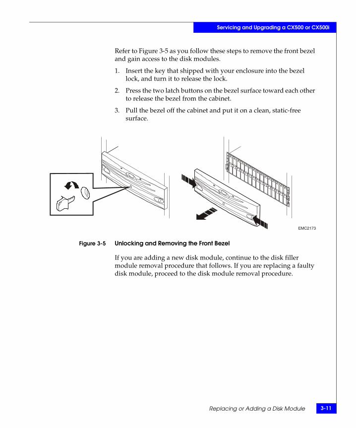
Replacing or Adding a Disk Module 3-11
Servicing and Upgrading a CX500 or CX500i
Refer to Figure 3-5 as you follow these steps to remove the front bezel and gain access to the disk modules.
1. Insert the key that shipped with your enclosure into the bezel lock, and turn it to release the lock.
2. Press the two latch buttons on the bezel surface toward each other to release the bezel from the cabinet.
3. Pull the bezel off the cabinet and put it on a clean, static-free surface.
Figure 3-5 Unlocking and Removing the Front Bezel
If you are adding a new disk module, continue to the disk filler module removal procedure that follows. If you are replacing a faulty disk module, proceed to the disk module removal procedure.
EMC2173

3-12 CX500/CX500i Hardware Reference
Servicing and Upgrading a CX500 or CX500i
Removing a Disk Filler ModuleLocate the slot where you want to install the disk module, and remove the filler module, as shown in Figure 3-6.
Figure 3-6 Removing a Disk Filler Module
Skip to the disk installation procedure (page 3-13) to install the add-on disk in the slot you just emptied.
Removing a Disk Module
CAUTION!If a disk module has been bound into a LUN, do not move it to another slot unless you do not care about the data on the LUN. Each module has LUN identifying information written when it is bound. Moving it to another slot can make information on the original LUN inaccessible.
The disk modules in slots 0-4 provide recovery and mirrored boot capability and are preloaded according to their slot assignment before shipment. Do not move a preloaded module from its assigned slot to another slot, and remove it only to replace the disk.
Generally, you should not remove a disk module unless its amber fault light is on. See Table 3-1.
EMC2210
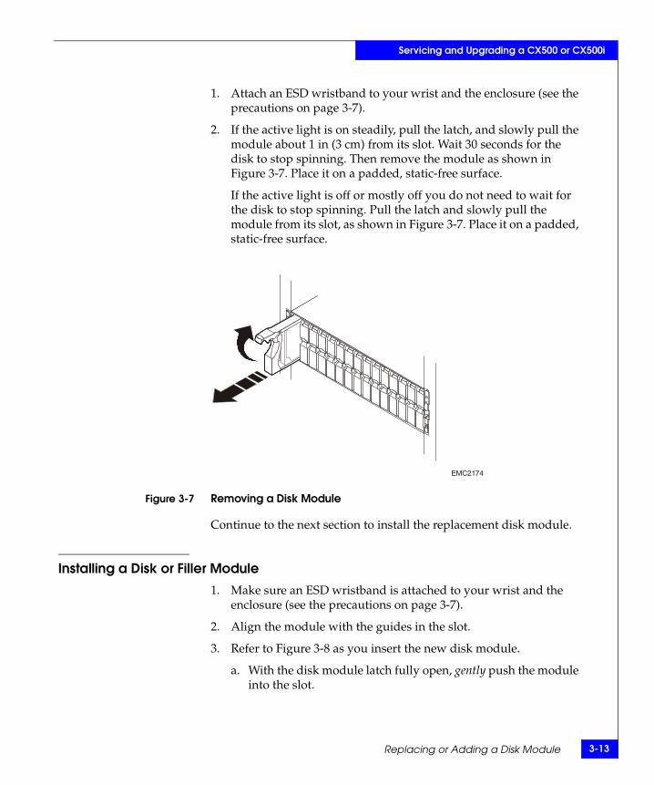
Replacing or Adding a Disk Module 3-13
Servicing and Upgrading a CX500 or CX500i
1. Attach an ESD wristband to your wrist and the enclosure (see the precautions on page 3-7).
2. If the active light is on steadily, pull the latch, and slowly pull the module about 1 in (3 cm) from its slot. Wait 30 seconds for the disk to stop spinning. Then remove the module as shown in Figure 3-7. Place it on a padded, static-free surface.
If the active light is off or mostly off you do not need to wait for the disk to stop spinning. Pull the latch and slowly pull the module from its slot, as shown in Figure 3-7. Place it on a padded, static-free surface.
Figure 3-7 Removing a Disk Module
Continue to the next section to install the replacement disk module.
Installing a Disk or Filler Module
1. Make sure an ESD wristband is attached to your wrist and the enclosure (see the precautions on page 3-7).
2. Align the module with the guides in the slot.
3. Refer to Figure 3-8 as you insert the new disk module.
a. With the disk module latch fully open, gently push the module into the slot.
EMC2174
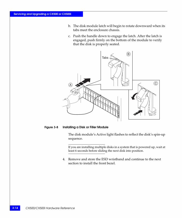
3-14 CX500/CX500i Hardware Reference
Servicing and Upgrading a CX500 or CX500i
b. The disk module latch will begin to rotate downward when its tabs meet the enclosure chassis.
c. Push the handle down to engage the latch. After the latch is engaged, push firmly on the bottom of the module to verify that the disk is properly seated.
Figure 3-8 Installing a Disk or Filler Module
The disk module’s Active light flashes to reflect the disk’s spin-up sequence.
If you are installing multiple disks in a system that is powered up, wait at least 6 seconds before sliding the next disk into position.
4. Remove and store the ESD wristband and continue to the next section to install the front bezel.
Tabs
A
B
C

Replacing or Adding a Disk Module 3-15
Servicing and Upgrading a CX500 or CX500i
Installing and Locking the Front BezelRefer to Figure 3-9 as you do the following:
1. Align the bezel with the disk enclosure.
2. Gently push the bezel into place on the cabinet until it latches.
3. Secure the bezel by turning the key in the lock.
Figure 3-9 Installing and Locking the Front Bezel
EMC2222

3-16 CX500/CX500i Hardware Reference
Servicing and Upgrading a CX500 or CX500i
Replacing a Storage Processor (SP)
CAUTION!Handle an SP gently and use an ESD wristband. Do not remove a faulty SP until you have a replacement module available.
A CX500/CX500i disk enclosure must have at least one SP installed while it is powered up. Do not remove both SPs while the disk enclosure is powered up.
Removing an SP1. Gently release the connectors as you remove the optical, copper,
LAN, and SPS cables connected to the SP.
Note where the cable(s) connect to the SP. You will need to reconnect them correctly to the replacement SP.
2. Turn the latch counterclockwise to release the module, and then remove the SP from its slot, as shown in Figure 3-10.
Figure 3-10 Removing an SP
EMC2727Latch
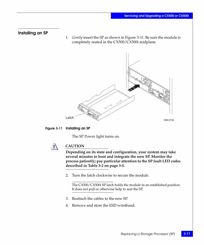
Replacing a Storage Processor (SP) 3-17
Servicing and Upgrading a CX500 or CX500i
Installing an SP1. Gently insert the SP as shown in Figure 3-11. Be sure the module is
completely seated in the CX500/CX500i midplane.
Figure 3-11 Installing an SP
The SP Power light turns on.
CAUTION!Depending on its state and configuration, your system may take several minutes to boot and integrate the new SP. Monitor the process patiently; pay particular attention to the SP fault LED codes described in Table 3-2 on page 3-5.
2. Turn the latch clockwise to secure the module.
The CX500/CX500i SP latch holds the module in an established position. It does not pull or otherwise help to seat the SP.
3. Reattach the cables to the new SP.
4. Remove and store the ESD wristband.
EMC2728Latch

3-18 CX500/CX500i Hardware Reference
Servicing and Upgrading a CX500 or CX500i
Replacing a Power Supply/System Cooling Module
CAUTION!Handle a power supply/system cooling (power/cooling) module gently and use an ESD wristband. Do not remove a power/cooling module until you have a replacement module available.
Access to the disks in your enclosure will time out and the disks will spin down two minutes after you remove a power/cooling module from the system. While the CX500/CX500i can continue operating on a single power supply, the loss of a module’s two blowers will cause a time-out unless you replace the module within two minutes.
Be sure the replacement power/cooling module has the same part number as the faulty CX500/CX500i module (as noted on the bar code label) or is an authorized substitution for the CX500/CX500i module.
If the power/cooling module includes a power switch, turn the switch to the off position before unplugging the power cord from the module or cabinet/rack power strip.
When replacing a power/cooling module, make certain the green LED on one module has been steadily on for at least 5 seconds before removing power from the second module.
Removing a Power/Cooling ModuleFollow these steps to replace a power/cooling module.
1. Turn any module power switch to off, then release any retention bail and unplug the ac/dc power cord. Figure 3-12 shows how to remove ac power cords; Figure 3-13 shows how to remove dc power cords.

Replacing a Power Supply/System Cooling Module 3-19
Servicing and Upgrading a CX500 or CX500i
Figure 3-12 Unplugging the ac Power Cord
To protect a running system from overheating, the enclosure will time out unless you replace the power/cooling module within two minutes.
Figure 3-13 Unplugging the dc Power Cord
EMC2729
acConnector
SpringRelease EMC3170

3-20 CX500/CX500i Hardware Reference
Servicing and Upgrading a CX500 or CX500i
2. Turn the latch counterclockwise to release the module, and then remove it as shown in Figure 3-14.
Figure 3-14 Removing a Power Supply/System Cooling Module
Continue to the next section to install the replacement module.
Installing a Power/Cooling Module1. Gently insert the new module into the enclosure, as shown in
Figure 3-15. Be sure the module is completely seated.
EMC2730
Latch

Replacing a Power Supply/System Cooling Module 3-21
Servicing and Upgrading a CX500 or CX500i
Figure 3-15 Installing a Power/Cooling Module
2. Turn the latch clockwise to secure the module.
The latch holds the power/cooling module in an established position. It does not pull or otherwise help to seat the module.
3. Make sure any power switch on the replacement module is off before you plug the ac/dc power cord into the new supply. On ac modules, attach the wire retention bail for strain relief (see Figure 3-16). Turn a power switch to the on position after you plug in the power cord.
EMC2731
Latch

3-22 CX500/CX500i Hardware Reference
Servicing and Upgrading a CX500 or CX500i
Figure 3-16 Plugging in the Power Cord
EMC2732
acConnector

The Standby Power Supply (SPS) 4-1
4
The standby power supply (SPS) provides ac backup power required to protect the integrity of the CX500 or CX500i’s storage processor write cache. This chapter describes the CX500/CX500i SPS and how to determine SPS status.
For instructions on installing or replacing an SPS, refer to the EMC Rails and Enclosures (CX-Series Storage Systems) Field Installation Guide.
IMPORTANT: The SPS is intended to provide ac backup power for DAE and CX-Series enclosures only.
Systems with dc power are intended for use in environments with redundant and highly available power sources (for example, "Central Office" grade power within the telecommunications industry), and dc power provided by the site must meet this requirement. The sudden loss of all incoming dc power to a storage system may cause unexpected abnormal behavior of the storage system and loss of write-cache data.
The Standby PowerSupply (SPS)

4-2 CX500/CX500i Hardware Reference
The Standby Power Supply (SPS)
About the SPSTwo 1000-watt dc SPSs provide backup power for one ac-powered CX500 or CX500i. The two SPSs provide higher availability and allow write caching — which prevents data loss during a power failure — to continue. A faulted or not fully charged SPS disables write caching.
Each SPS rear panel has one ac inlet power connector with power switch, an ac outlet for the DPE2, another ac outlet which you should not use in CX500/CX500i configurations, one data connector to the storage processor, and status lights (LEDs).
IMPORTANT: Improper storage and handling of an SPS will render the warranty null and void. Please see Appendix A for appropriate SPS storage requirements.
Figure 4-1 shows the SPS unit, removed from its cabinet mounting.
Figure 4-1 CX500/CX500i SPS Rear Panel
See Table 4-1 for the meanings of the SPS status LEDs.
EMC2725
acPowerConnector
PowerSwitch
SPInterface
To Power/CoolingModule
ActiveLED(Green)
ReplaceBatteryLED(Amber)
On BatteryLED(Amber)
FaultLED(Amber)
Do Not Use
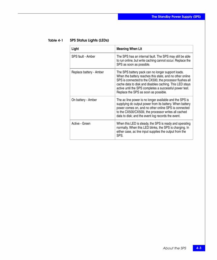
About the SPS 4-3
The Standby Power Supply (SPS)
Table 4-1 SPS Status Lights (LEDs)
Light Meaning When Lit
SPS fault - Amber The SPS has an internal fault. The SPS may still be able to run online, but write caching cannot occur. Replace the SPS as soon as possible.
Replace battery - Amber The SPS battery pack can no longer support loads. When the battery reaches this state, and no other online SPS is connected to the CX500, the processor flushes all cache data to disk and disables caching. This LED stays active until the SPS completes a successful power test. Replace the SPS as soon as possible.
On battery - Amber The ac line power is no longer available and the SPS is supplying dc output power from its battery. When battery power comes on, and no other online SPS is connected to the CX500/CX500i, the processor writes all cached data to disk; and the event log records the event.
Active - Green When this LED is steady, the SPS is ready and operating normally. When this LED blinks, the SPS is charging. In either case, ac line input supplies the output from the SPS.

4-4 CX500/CX500i Hardware Reference
The Standby Power Supply (SPS)
The two SPS units fit in a tray beneath the CX500/CX500i to which they connect. Figure 4-2 shows the SPS in a cabinet with a CX500.
Figure 4-2 SPS Installation, Front and Rear Views
In the event of a power failure, an SPS provides backup power until the storage processor has flushed its write cache data to the CX500/CX500i disks. The storage processor then shuts the SPS power off. If the cache flush has not completed within 90 seconds — more than enough time to flush a full cache — or if the storage processor has failed, then the SPS shuts itself down to prevent deep discharge. If there is no ac inlet power and the SPS is shut down, all status lights will be off.
When power returns, the SPS starts recharging. It may reach a state of full charge relatively quickly. If power remains off for a long period — days or weeks — the battery may require more time to charge fully. The storage processor will not use the write cache unless it detects at least one fully charged SPS.
Battery lifetime depends on the number of discharge cycles and depth of discharge. In a typical environment, a battery pack can last 3 to 5 years. Battery pack lifetime is shorter in locations that have frequent ac outages.
EMC2733
Standby PowerSupply B (SPS B)
Standby PowerSupply A (SPS A)
Rear
Front
Mounting Tray withStandby Power Supplies(Behind the Bezel)
Technical Specifications and Operating Limits A-1
AInvisible Body Tag
This appendix describes the disk processor enclosure technical specifications, operating limits, and shipping and storage requirements. Major topics are
CX500/CX500i DPE2 Technical Specifications .............................A-2 Standards Certification and Compliance.......................................A-7 Operating Limits ...............................................................................A-9 SPS Technical Specifications ..........................................................A-13
TechnicalSpecifications and
Operating Limits

A-2 CX500/CX500i Hardware Reference
Technical Specifications and Operating Limits
CX500/CX500i DPE2 Technical SpecificationsTechnical specifications include power requirements, size, drive, interface, and standards information.
Power Requirements
The input current, power (VA), and dissipation per CX500/CX500i DPE2 are based on the maximum capability of the power supplies and cooling system to provide internal regulated power. Typical values will be less, depending on the number and manufacturer of disk modules. These values represent either
the values for a single power supply line cord, or
the sum of the values shared by the line cords of two power supplies in the same enclosure, with the division between the line cords and supplies at the current sharing ratio (approximately 50% each).
A failure of one of the two power supplies in the DPE2 results in the remaining supply and cord supporting the full load. You must use a rackmount cabinet or rack with appropriate power distribution, and have main branch ac/dc distribution that can handle these values for each CX500/CX500i in the cabinet.
* A fully configured DPE2 includes 2 power supplies, 2 SPs, and 15 disk drives.
CX500/CX500i ac Ratings
Requirement Description
ac line voltage 100 to 240 V ac + 10%, single phase, 47 to 63 Hz
ac line current 5.9 A at 100 V ac, 2.9 A at 200 V ac
Power consumption 590 VA (578 W) max (fully configured)*
Power factor 0.98 min at full load, low voltage
Heat dissipation 2.08 106 J/hr (1,975 BTU/hr) max *
In-rush current 25 A max for 1/2 line cycle, per power supply at 240 V ac15 A max for 1/2 line cycle, per power supply at 120 V ac
Startup surge current 15 Apk (10.6 Arms) max for 100 ms, at any line voltage
ac protection 10 A fuse in each power supply, both phases
ac receptacle type IEC320-C14 appliance coupler, per power supply
Ride-through time 30 ms min
Current sharing 60% max, 40% min, between power supplies

CX500/CX500i DPE2 Technical Specifications A-3
Technical Specifications and Operating Limits
CX500 dc Ratings
Requirement Description
dc line voltage -36 V to -72 V dc (Nominal -48V or -60V power systems)
dc line current 16 A max at -36 V dc, 12 A typ at -48 V dc
Power consumption 580 W max
Heat dissipation 2.09 x 10⁶ J/hr, (1,980 BTU/hr) max
In-rush current 30 A peak, per requirements in EN300 132-2 Sect. 4.7 limit curve
dc protection 30 A fuse on each power supply, both phases
dc inlet type Positronic Industries PLB3W3M1000
Mating dc Connector Positronic Industries PLB3W3F7100A1
Ride-through time 5 ms min
Current sharing 60% max, 40% min between power supplies
Summary of CX500 dc Power Supply Characteristics
Overall Output Power 575W
Individual Output Ratings Min Current Max Current Regulation Ripple (p-p
12 V_1 1.5A 21A +/-3% 120mV
12 V_2 1.5 A 21A +/-3% 120mV
B_PWR_x_y (9V-13.2V out) .4A 5.4A +/-5% 120mV
+5V 0A 1.5A +/-4% 75mV
Note: Total of all outputs combined not to exceed 575W

A-4 CX500/CX500i Hardware Reference
Technical Specifications and Operating Limits
Size and Weight
Drive Type Fibre Channel interface disk drives used in CX500/CX500i enclosures are
8.75 cm (3.5 inches) tall
2.54 cm (1.0 inch) wide
12 volt only
Drive module power is 16 W maximum per drive slot.
DPE2 FC-AL InterfaceConnector - shielded HSSDC (High Speed Serial Data Connector).
Measurement CX500/CX500i DPE2 SPS
Height 133.35 mm (5.25 in) 3 NEMA units including mounting hardware
4.02 cm (1.58 in) 1 U, including mounting rails
Width 450 mm (17.72 in) 20.96 cm (8.25 in) each
Depth 603.25 mm (23.75 in) 60.33 cm (23.75 in)
Weight 44.5 kg (98.3 lbs) maximum configuration1.1 kg (2.4 lbs) per disk module1.7 kg (3.8 lbs) per storage processor4.1 kg (9 lbs) per power supply12.7 kg (28 lbs) chassis and midplane
10.7 kg (23.65 lbs) each4.5 kg (9.85 lbs) tray25.9 kg (57.15 lbs) max total (2 SPS)
Measurement DAE2 DAE2P
Height 133.35 mm (5.25 in) 3 NEMA units including mounting hardware
Width 450 mm (17.72 in)
Depth 603.25 mm (23.75 in) 355.6 mm (14 in)
Weight 43.2 kg (95.3 lbs) with rails (fully configured) 30.91 kg (68 lbs) maximum configuration;

CX500/CX500i DPE2 Technical Specifications A-5
Technical Specifications and Operating Limits
Copper Cabling The expansion port interface to the DPE2 is copper cable.
Storage Processor Optical Cabling (CX500)The CX500 uses optical cable from the SP’s SFF (Small Form Factor) LC transceivers to the external Fibre Channel environment.
The maximum length when using either the 62.5 µm or 50 µm cable (noted in the table above) includes two connections or splices between the source and destination. For a detailed overview of cable types, connections, and lengths, refer to the EMC CLARiiON CX300, CX300i, CX500, and CX700 Storage Systems Configuration Planning Guide.
CAUTION!EMC does not recommend mixing 62.5 µm and 50 µm optical cables in the same link. In certain situations you can add a 50 µm adapter cable to the end of an already installed 62.5 µm cable plant. Contact your EMC representative for details.
Storage Processor Ethernet Cabling (CX500i)The CX500i uses standard Ethernet LAN cables from the 1-gigabit LAN ports (RJ45 connectors) on each SP to the external network environment. For distances up to 100 meters, Category 5E cables are the commonly used gigabit Ethernet standard; the system also
Typea: Shielded, 150Ω differential, shield bonded to HSSDC plug connector shell (360°)FC-PI Standard, Revision 13 or higher
Length: 1 meter (3.3 feet) unequalized;5 meters (16.5 feet) and 10 meters (33 feet) equalized
a. Refer to your DAE Hardware Reference for detailed back-end cable types and lengths.
Type 50 µm or 62.5 µm, multi-mode, dual LC
Length 50 µm1.0625 Gbit 2 m (6.6 ft) minimum to 500 m (1,650 ft) maximum
2.125 Gbit 2 m (6.6 ft) min to 300 m (985 ft) maximum
Length 62.5 µm1.0625 Gbit 2 m (6.6 ft) min to 300 m (985 ft) maximum
2.125 Gbit 2 m (6.6 ft) min to 150 m (492 ft) maximum
Bend Radius 3 cm (1.2 in) min

A-6 CX500/CX500i Hardware Reference
Technical Specifications and Operating Limits
supports CAT 5 and CAT 6 cables. EMC recommends CAT 6 LAN cables whenever possible.
All iSCSI data port (front end) connections must be 1-gigabit LAN, even if the server NIC connection is 10/100; the CX500i supports 10/100 LAN connection to the management ports only.
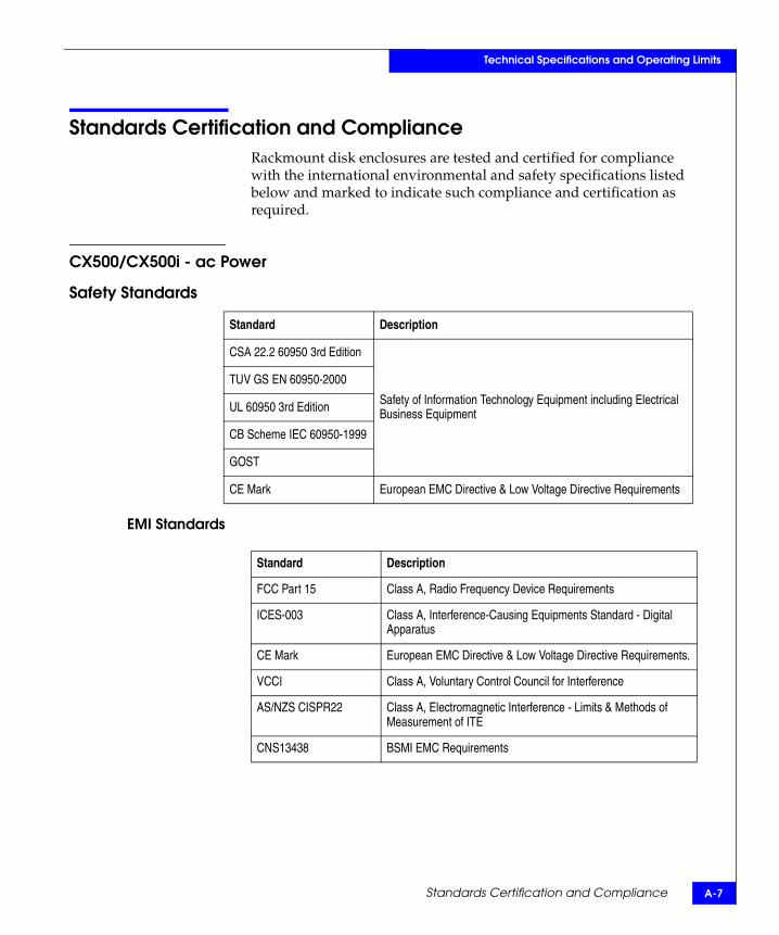
Standards Certification and Compliance A-7
Technical Specifications and Operating Limits
Standards Certification and ComplianceRackmount disk enclosures are tested and certified for compliance with the international environmental and safety specifications listed below and marked to indicate such compliance and certification as required.
CX500/CX500i - ac Power
Safety Standards
EMI Standards
Standard Description
CSA 22.2 60950 3rd Edition
Safety of Information Technology Equipment including Electrical Business Equipment
TUV GS EN 60950-2000
UL 60950 3rd Edition
CB Scheme IEC 60950-1999
GOST
CE Mark European EMC Directive & Low Voltage Directive Requirements
Standard Description
FCC Part 15 Class A, Radio Frequency Device Requirements
ICES-003 Class A, Interference-Causing Equipments Standard - Digital Apparatus
CE Mark European EMC Directive & Low Voltage Directive Requirements.
VCCI Class A, Voluntary Control Council for Interference
AS/NZS CISPR22 Class A, Electromagnetic Interference - Limits & Methods of Measurement of ITE
CNS13438 BSMI EMC Requirements
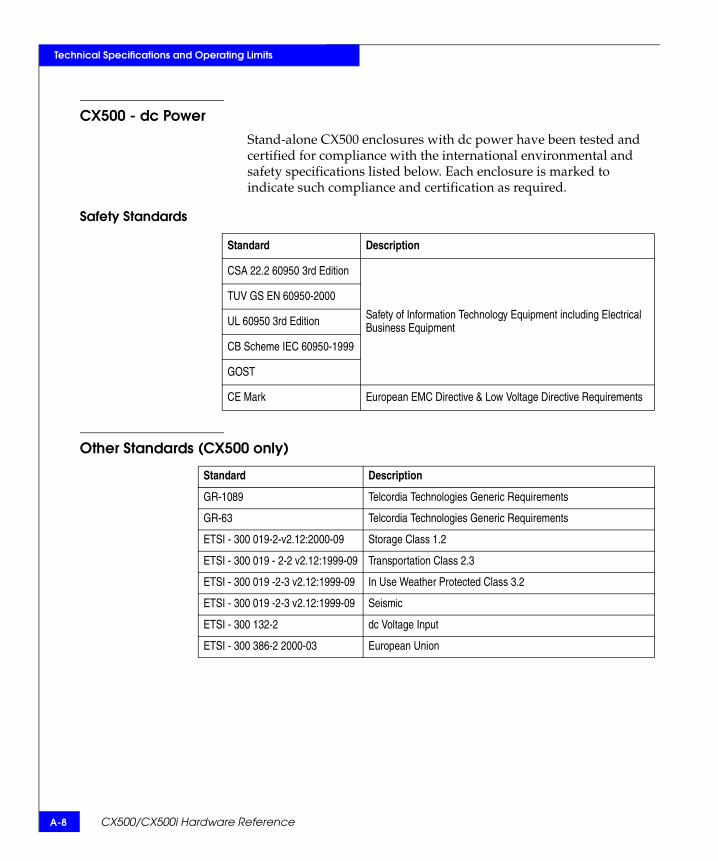
A-8 CX500/CX500i Hardware Reference
Technical Specifications and Operating Limits
CX500 - dc PowerStand-alone CX500 enclosures with dc power have been tested and certified for compliance with the international environmental and safety specifications listed below. Each enclosure is marked to indicate such compliance and certification as required.
Safety Standards
Other Standards (CX500 only)
Standard Description
CSA 22.2 60950 3rd Edition
Safety of Information Technology Equipment including Electrical Business Equipment
TUV GS EN 60950-2000
UL 60950 3rd Edition
CB Scheme IEC 60950-1999
GOST
CE Mark European EMC Directive & Low Voltage Directive Requirements
Standard Description
GR-1089 Telcordia Technologies Generic Requirements
GR-63 Telcordia Technologies Generic Requirements
ETSI - 300 019-2-v2.12:2000-09 Storage Class 1.2
ETSI - 300 019 - 2-2 v2.12:1999-09 Transportation Class 2.3
ETSI - 300 019 -2-3 v2.12:1999-09 In Use Weather Protected Class 3.2
ETSI - 300 019 -2-3 v2.12:1999-09 Seismic
ETSI - 300 132-2 dc Voltage Input
ETSI - 300 386-2 2000-03 European Union

Operating Limits A-9
Technical Specifications and Operating Limits
Fibre Channel Related Standards
Note: In some cases, the DPE2 uses functions from later revisions of specifications.
Operating LimitsThe ambient temperature specification is measured at the front panel inlet. The site must have air conditioning of the correct size and placement to maintain the specified ambient temperature range and offset the CX500/CX500i heat dissipation listed on page A-2.
The operating limits listed above for temperature and humidity must not be exceeded inside the closed cabinet in which the CX500/CX500i is mounted. Mounting equipment in a cabinet directly above or below a CX500/CX500i does not restrict air flow to the DPE2; air flows through the storage system from front to back at a rate of approximately 120 cubic feet per minute. Cabinet doors must not impede the front to back air flow. Exhaust temperatures will rise approximately 12° C (21.6° F) above intake temperatures.
Standard Description
Fibre Channel Physical and signaling interface, FC-PI, draft Rev. 13
Fibre Channel Arbitrated Loop (FC-AL), Revision 4.5
Fibre Channel Private Loop Direct Attach (PLDA), Revision 2.1
SCSI III SCSI Enclosure Services (SES), Revision 8a
Requirement Description
Ambient temperature 10°C to 40°C (50°F to 104°F)
Temperature gradient 10°C/hr (18°F/hr)
Relative humidity 20% to 80% noncondensing
Elevation 2438 m (8000 ft) at 40°C3077 m (10,000 ft) at 37°C

A-10 CX500/CX500i Hardware Reference
Technical Specifications and Operating Limits
Environmental RecoveryIf the system exceeds maximum ambient temperature by approximately 10°C/18°F, the storage processors will begin an orderly shutdown that saves cached data, shuts off the SPs, and — in a DPE2 enclosure — powers down the disks. LCCs in each DAE will power down their disks but remain powered on. If the system detects that the temperature has dropped to an acceptable level, it restores power to the storage processors (which power up any disks in their enclosure) and the LCCs restore power to their disk drives.
Shipping and Storage Requirements
Requirement Description
Ambient temperature -40oC to 65oC (-40oF to 149oF)
Temperature gradient 25oC/hr (45oF/hr)
Relative humidity 10% to 90% noncondensing
Elevation 7625 m (25,000 ft)
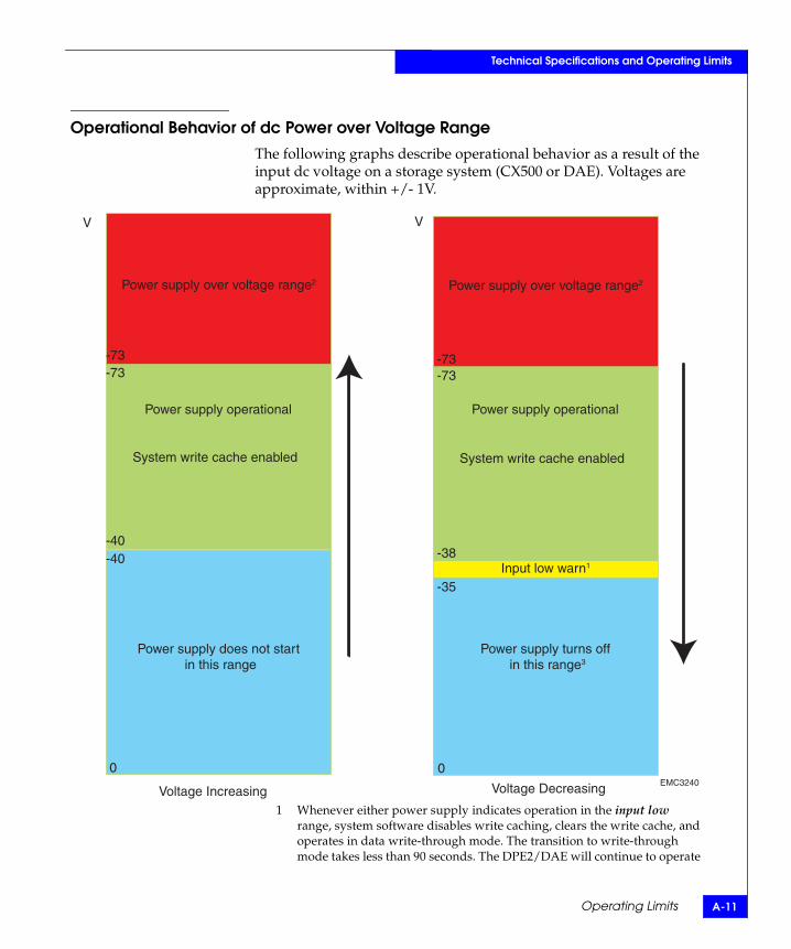
Operating Limits A-11
Technical Specifications and Operating Limits
Operational Behavior of dc Power over Voltage RangeThe following graphs describe operational behavior as a result of the input dc voltage on a storage system (CX500 or DAE). Voltages are approximate, within +/- 1V.
1 Whenever either power supply indicates operation in the input low range, system software disables write caching, clears the write cache, and operates in data write-through mode. The transition to write-through mode takes less than 90 seconds. The DPE2/DAE will continue to operate
Power supply over voltage range2Power supply over voltage range2
Power supply operational
System write cache enabled
Power supply does not start in this range
System write cache enabled
Power supply operational
Input low warn1
Power supply turns off in this range3
-35
-38
-73
-40
-73-73-73
-40
00
VV
Voltage Increasing Voltage Decreasing EMC3240
A-12 CX500/CX500i Hardware Reference
Technical Specifications and Operating Limits
in write-through mode while the power remains in input low range. This operating mode is intended to detect a slowly decaying battery bus and allows the enclosure to prepare for a possible shutdown, should input power be lost on both inputs. Write caching will automatically be re-enabled once both supplies return to the normal operational range.
2 Power supplies in the overvoltage range will continue to operate with no change in system behavior. Excessive overvoltage conditions may damage the unit and create a power supply fault for that supply. If the system recognizes a power supply fault condition, it disables write caching, clears the write cache, and operates in data write-through mode until the supply is replaced.
3 If both power supplies transition from the normal operational range to the off range in less than 90 seconds, write-cache memory may lose data and compromise the data in the storage system. Always disable write cache before removing power from both input busses.

SPS Technical Specifications A-13
Technical Specifications and Operating Limits
SPS Technical SpecificationsThis section lists the technical specifications and operating limits for the standby power supply (SPS).
SPS to SP Interface
Power Specifications
Type: Half-duplex RS-232
Baud rate: 9600, 8-bit
Parity: None
Requirement Description (All Ratings Assume a Fully Configured System)
ac line voltage 100 V ac to 240 V ac -10%/+10% single-phase, 47 Hz to 63 Hz; auto-ranging
ac line current,internal and pass-through
0.2 A max @ 100 V ac, internal current consumption (up to 10 A max at 100 V ac, pass-through to ac outlets)0.1 A max @ 200 V ac, internal current consumption(up to 5 A max @ 200 V ac, pass-through to ac outlets)
Internal power consumption 60 VA (40 W) peak in hi-charge mode10 VA (6 W) float charge mode
Power factor NA for pass-through load; .67 pf for internal 10 VA load
Heat dissipation 21.6 x 10³ J/hr, (21 BTU/hr) steady state
In-rush current 6 A max for 1/2 line cycle @ 240 V ac
ac protection 15 A fuse, both phases
Chassis power inlet IEC 320-C14 Appliance Connector (panel mount)
Chassis power outlet EC 320-C13 Appliance Connector (panel mount) (2)
Charge times After full power outage, 75 minutes maximum (45 minutes typically)After off-line storage, 2 hours approximately
ac failure detect time 12 ms max
Transfer time 28 ms maximum
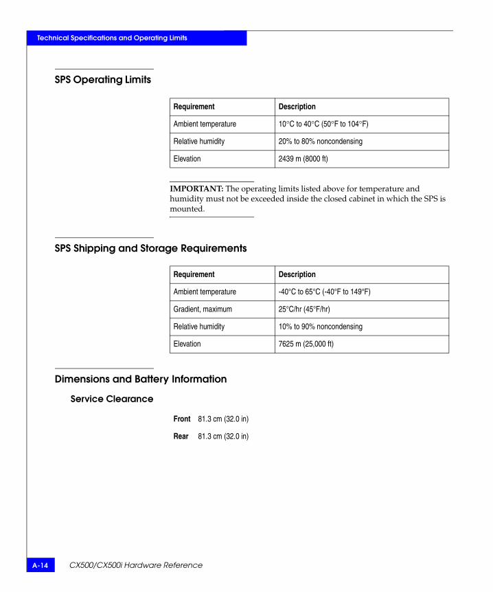
A-14 CX500/CX500i Hardware Reference
Technical Specifications and Operating Limits
SPS Operating Limits
IMPORTANT: The operating limits listed above for temperature and humidity must not be exceeded inside the closed cabinet in which the SPS is mounted.
SPS Shipping and Storage Requirements
Dimensions and Battery Information
Service Clearance
Requirement Description
Ambient temperature 10°C to 40°C (50°F to 104°F)
Relative humidity 20% to 80% noncondensing
Elevation 2439 m (8000 ft)
Requirement Description
Ambient temperature -40°C to 65°C (-40°F to 149°F)
Gradient, maximum 25°C/hr (45°F/hr)
Relative humidity 10% to 90% noncondensing
Elevation 7625 m (25,000 ft)
Front 81.3 cm (32.0 in)
Rear 81.3 cm (32.0 in)

SPS Technical Specifications A-15
Technical Specifications and Operating Limits
Battery Tests
Battery Self-Discharge TimesWhen you store an SPS, the battery charge level naturally decreases over time. This is characteristic of all rechargable batteries. The rate of self-discharge depends on temperature. Lower storage temperatures are desirable since the self-discharge rate is lower. The following graph shows how the remaining charge decreases over time at different temperatures.
Figure A-1 Typical SPS Self-Discharge Levels at Different Storage Temperatures
Internal Within 60 minutes after powerup and approximately every 2 weeks thereafter, the SPS performs a light test on the batteries. This test lasts less than one second. It does not verify battery capacity but does check connectivity and functionality. This test is transparent to other components in the storage system. If an actual power failure occurs during the test, the test is terminated and the unit goes into On-Battery mode.
Full At each storage-system startup, the system software initiates a full power test. During the test, the system disables write cache and allows the SPS to stay on for its entire 90-second period. The system initiates a full test when the SPS is online and fully charged. If the batteries are charging at test time, the system defers the test until the next programmed time.
Avoid allowing the batteryto discharge below thislevel to allow full rechargewithin the SPS time limit.
20 degrees C (68 F)30 degrees C (88 F)40 degrees C (104 F)
100
90
80
70
60
50
40
30
20
10
03 6 9 12 15 18
Rem
aini
ng C
apac
ity (
%)
Storage Time (Months) EMC2447

A-16 CX500/CX500i Hardware Reference
Technical Specifications and Operating Limits
IMPORTANT: If you are storing an SPS, do not store it longer than 6 months or at a temperature exceeding 30° C without recharging it. When you retrieve an SPS unit from storage, you should charge it by connecting it to ac power, with its power switch in the on position, for at least 12 hours before putting it into service or returning it to storage.
SPS Standards Certification/Compliance
A stand-alone SPS has been tested and certified for compliance with the international environmental and safety specifications listed below. The SPS is marked to indicate such compliance and certification as required.
Safety Standards
EMI Standards
Standard Description
EN 60950 Safety of Information Technology Equipment including Electrical Business Equipment.UL 1950
CSA 22.2 No. 950
Standard Description
FCC Part 15 Class B, Radio Frequency Device Requirements
ICES-003 Class B, Interference-Causing Equipments Standard - Digital Apparatus
CE Mark European EMC Directive & Low Voltage Directive Requirements.
VCCI Class B, Voluntary Control Council for Interference
AS/NZS CISPR22 Class B, Electromagnetic Interference - Limits & Methods of Measurement of ITE
CNS13438 BSMI EMC Requirements
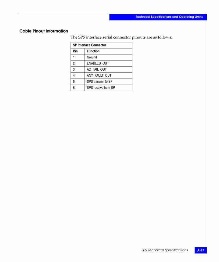
SPS Technical Specifications A-17
Technical Specifications and Operating Limits
Cable Pinout InformationThe SPS interface serial connector pinouts are as follows:
SP Interface Connector
Pin Function
1 Ground
2 ENABLED_OUT
3 AC_FAIL_OUT
4 ANY_FAULT_OUT
5 SPS transmit to SP
6 SPS receive from SP

A-18 CX500/CX500i Hardware Reference
Technical Specifications and Operating Limits
Customer Support B-1
Bnvisible Body Tag
This appendix reviews the EMC process for detecting and resolving software problems, and provides essential questions that you should answer before contacting the EMC Customer Support Center.
This appendix covers the following topics:
Overview of Detecting and Resolving Problems ......................... B-2 Troubleshooting the Problem .......................................................... B-3 Before Calling the Customer Support Center ............................... B-4 Documenting the Problem............................................................... B-5 Reporting a New Problem ............................................................... B-6 Sending Problem Documentation................................................... B-7
Customer Support

B-2 CX500/CX500i Hardware Reference
Customer Support
Overview of Detecting and Resolving ProblemsEMC software products are supported directly by the EMC Customer Support Center in the United States.
EMC uses the following process to resolve customer problems with its software products (Figure B-1).
Figure B-1 Problem Detection and Resolution Process
ProblemDetection
Refer to thisCustomer Support
Appendix for Instructions
Collect ProblemInformation as
Directed
Contact the EMC CustomerSupport Center:
U.S.:Canada:Worldwide:
(800) SVC-4EMC(800) 543-4SVC(508) 497-7901
Confirm that theProblem is Software
Related
Call will be Directedto an EMC SoftwareSupport Engineer
Problem isTracked andManaged toResolution

Troubleshooting the Problem B-3
Customer Support
Troubleshooting the ProblemPlease perform the relevant diagnostic steps before you contact the EMC Customer Support Center:
1. Read the documentation carefully.
2. Reconstruct the events leading up to the problem and describe them in writing.
3. Run some test cases to reproduce the problem.
If you encounter a problem that requires technical programming or analysis, call the nearest EMC office or contact the EMC Customer Support Center at one of the following numbers:
United States: (800) 782-4362 (SVC-4EMC)
Canada: (800) 543-4782 (543-4SVC)
Worldwide: (508) 497-7901
Please do not request a specific support representative unless one has already been assigned to your particular system problem.
For additional information on EMC products and services available to customers and partners, refer to the EMC Powerlink website at:
http://powerlink.EMC.com

B-4 CX500/CX500i Hardware Reference
Customer Support
Before Calling the Customer Support CenterHave the following information available before calling the Customer Support Center or your support representative (if one has been assigned to you):
Your company name
Your name
Your phone number
Your site ID, if known
For an existing problem, the problem tracking system ID, if one was previously assigned to the problem by a support representative
Documenting the Problem B-5
Customer Support
Documenting the ProblemIf the EMC Customer Support Center requests information regarding the problem, please document it completely, making sure to include the following information:
Your company name and address
Your name
Your telephone number
Your site ID
The importance of the problem, so that it can be assigned a priority level
To expedite the processing of your support request, you can photocopy this list and include it with the package.

B-6 CX500/CX500i Hardware Reference
Customer Support
Reporting a New ProblemFor a new problem, please provide the following information:
Release level of the software that you are running
Software installation parameters
Host type on which you are running
Operating system you are running and its release number
Functions of the software that you are running
Whether you can reproduce the problem
Previous occurrences of the problem
Whether the software has ever worked correctly
Time period that the software did work properly
Conditions under which the software worked properly
Changes to your system between the time the software worked properly and the problem began
Exact sequence of events that led to the system error
Message numbers and complete text of any messages that the system produced
Log file dated near the time the error occurred
Results from tests that you have run
Other related system output
Other information that may help solve the problem

Sending Problem Documentation B-7
Customer Support
Sending Problem DocumentationUse one of the following methods to send documentation of the problem to the EMC Customer Support Center:
FTP
U.S. mail to the following address:
EMC Customer Support Center171 South StreetHopkinton, MA 01748-9103
If the problem was assigned a number or a specific support representative, please include that information in the address as well.

B-8 CX500/CX500i Hardware Reference
Customer Support

CX500/CX500i Hardware Reference g-1
Glossary
The terms defined here are important to installing and maintaining a storage system.
AALPA (arbitrated loop
physical address)An 8-bit address that uniquely identifies an SP (or other device) on an FC-AL loop.
bind In the context of a disk-array storage system, the procedure by which you format one or more disk modules into one LUN (logical unit) — usually as one of several types of RAID group.
Ccache See storage-system caching.
CRU (customer-replaceable unit)
A hardware component, such as a disk module, that anyone can replace.
DDAE (disk-array
enclosure)A storage device that includes an enclosure, disk modules, LCCs, cooling modules, and power supplies. The 2-gigabit disk-array enclosures ((DAE2 and DAE2P) ) supported in CX500/CX500i systems can hold 0-15 disks.
DIMM (dual in-linememory module)
A type of memory module used in SP memory for caching or RAID 3.

g-2 CX500/CX500i Hardware Reference
Glossary
disk-drive module Another name for disk module.
disk module A self-contained disk drive that slides into one of the slots in the front of the enclosure. The carrier assembly holds the disk drive.
disk unit A short name for physical disk unit.
DPE (Disk ProcessorEnclosure)
A storage device that includes an enclosure, disk modules, storage processors, cooling modules, and power supplies.
EEA (enclosure
address)A number, selectable on a DPE2 or DAE rear panel — fixed at 0 on a CX500/CX500i — that helps establish a unique address for each disk module on an FC-AL loop. You must set the EA on each DAE. Since the CX500/CX500i EA is 0, you might set the first DAE EA on loop 0 to 1, and loop 1 EAs to 0 and 1.
EMI (electromagneticinterference)
Electronic radiation emitted by an electrical device. The levels of EMI are strictly controlled for data processing equipment. The EMI standards to which the CX500/CX500i complies are listed in Appendix A of this manual.
ESD (electrostaticdischarge)
The discharge of an accumulated electrical charge (static). This can severely damage delicate electronic circuits so you should take steps to prevent this, as explained in Chapter 3 of this manual.
Ffailover The transfer of one or more LUNs from one SP to another if a failure
occurs in the path of the original SP. Unassisted failover requires properly configured paths between a host and each SP, and failover/multipath software such as EMC PowerPath®.
FC-AL (Fibre Channelarbitrated loop)
An arrangement of Fibre Channel stations such that messages pass from one to the next in a ring.
Fibre Channel hostbus adapter (FC
adapter)
The name for the printed-circuit board within the computer chassis that allows the server to access the Fibre Channel loop and thus the SP(s). Also called a host bus adapter (HBA).
FC-SW (Fibre Channelswitch)
An arrangement of Fibre Channel stations into a fabric. Switch devices in the fabric redirect incoming data out other ports.
CX500/CX500i Hardware Reference g-3
Glossary
field-replaceableunit
See FRU (field-replaceable unit).
FRU(field-replaceable
unit)
A hardware assembly that can be replaced by trained personnel on site, instead of at the point of manufacture.
GGBIC Gigabit Interface Converter. A device for converting Fibre Channel
signals from electrical to optical, and vice versa.
HHBA (host bus
adapter)Another name for Fibre Channel host bus adapter.
host See server.
hot repair See replace under power.
hub An FC_AL switching device that allows multiple servers and targets such as storage systems to connect at a central point. A single hub configuration appears as a single loop.
LLCC (link control
card)A FRU in DAE enclosures, integrated into the SP module in a CX500. An LCC connects Fibre Channel signalling to the disk modules, and provides Fibre Channel connectivity between the SP, disks, and other enclosures. It also provides bypass capability for faulted or missing units, and monitors and controls enclosure elements.
LUN (logical unit) One or more disk modules (each having a head assembly and spindle) bound into a group — usually a RAID group. The operating system sees the LUN, which includes one or more disk modules, as one contiguous span of disk space.
Mmemory module See SP memory module.
g-4 CX500/CX500i Hardware Reference
Glossary
Nnode Any device with a Fibre Channel interface (such as an HBA in a
server or a storage system’s SP) that connects to a Fibre Channel loop.
PPDU (power
distribution unit)A device for the distribution of ac line power from one inlet to multiple outlets. Multiple PDUs in a rackmount cabinet provide higher availability since the power continues if one PDU (or its ac source, if the PDUs use separate ac sources) loses power.
power supply A device to connect ac main power to low voltage dc power for the system components. A storage system can have two power supplies, PS A and PS B. With two, it can survive failure of one supply. You can replace a power supply under power, without interrupting applications.
Rreplace under
powerThe capability that allows you to replace a FRU (for example, a disk module or a fan module) without powering down the storage system. Applications continue while you replace the failed module.
SSCSI (small computer
system interface)A well-known protocol and standard for connecting computers and peripheral devices. Some Fibre Channel SPs use a Fibre Channel FC-AL front end to the server and a SCSI back end to the disk modules. The SPs used in DPEs use the Fibre Channel protocol throughout. The array uses SCSI protocol over Fibre Channel.
server In the context of storage systems, a processor that runs an operating system and uses a disk-array storage system for data storage and retrieval.
SP (storageprocessor)
A printed-circuit board with processor memory modules and control logic that manages the storage-system I/O between the server FC adapter and the disk modules.
SP memorymodule
A memory module that provides the local storage for an SP.
CX500/CX500i Hardware Reference g-5
Glossary
SPS (standby powersupply)
A unit that provides temporary backup power in case of a power outage. An SPS is required for storage-system write caching. If power fails, the SPS allows the SP to write the data from its cache to disk. You can replace an SPS under power, without interrupting applications.
storage processor(SP)
See SP (storage processor).
storage-systemcaching
The procedure of temporarily storing disk-based data in SP memory to save time if the data is needed again soon.

g-6 CX500/CX500i Hardware Reference
Glossary

CX500/CX500i Hardware Reference i-1
Aac power cord
attaching to power supply 3-22removing from power supply 3-19
ac power, current draw A-2Active light
power supply 3-5SP 3-5
addressing requirements 2-3ALPA (Arbitrated Loop Physical Address)
defined g-1avoiding electrostatic discharge damage (ESD)
3-6
Bback end, defined 1-8battery 4-4binding disk modules g-1
Ccabinet, installing DPE2 in 2-5cable pinout information
SPS A-17cables
connecting 2-18copper
specifications A-5cabling
precautions 3-8requirements 2-2
certificationDPE2 A-7SPS A-16
chassis, see enclosure
Check lightpower supply 3-5SP 3-5
complianceDPE2 A-7SPS A-16
Cooling Check light 3-5copper cabling
specifications A-5CRU g-1current draw, DPE2 A-2Customer support B-3Customer Support Center B-7
DDAE (disk-array enclosure)
addressing requirements 2-7EA setting 2-8defined g-1
description 1-6discharge times, SPS A-15, A-17disk drive
description 1-9specifications A-4
disk filler modulesinstalling 3-13
disk moduleadding 3-9defined g-2disk drive 1-9drive carrier 1-9drive specifications A-4replacing 3-9status lights 1-4
DPE2 (2-gigabit disk processor enclosure)
Index

CX500/CX500i Hardware Referencei-2
Index
components 1-3enclosure
description 1-4front panel 1-5
front paneldescription 1-5
installing in cabinet 2-5monitoring status 3-2operating limits A-9power supply 1-9powering down 3-6powerup and initialization sequence 2-21requirements
cabling 2-2operating A-9
technical specifications A-2drive carrier description 1-9
EEA (enclosure address)
about 2-4defined g-2requirements 2-7setting 2-8
electromagnetic interference (EMI)shield 1-6standards certification/compliance A-7
electrostatic discharge (ESD)avoiding damage 3-6
EMI (electromagnetic interference)defined g-2
enclosuredescription 1-4front panel
description 1-4midplane description 1-6
ESD (electrostatic discharge)avoiding damage from 3-6defined g-2
Ffabric environment 2-3FC-AL (Fibre Channel Arbitrated Loop)
address ID, defined g-2back end (LCC) 1-8
cablingcopper A-5
requirements 2-2optical A-5
requirements 2-2connector A-4interface specifications A-4physical address 2-7powerup 2-23
Fibre Channeladapter (FC adapter) g-2related standards A-9
front bezel 1-6unlocking and opening 3-11
front paneldescription 1-5
FRUs (field-replaceable units) g-3defined 1-4disk module
adding 3-9defined g-2description 1-8removing 3-12replacing 3-9
handling 3-5power issues 3-5power supply
adding 3-18defined g-4description 1-9replacing 3-18
SPadding 3-16defined g-4description 1-7, 1-8replacing 3-16
storing 3-5technical specifications A-2
Ggrounding 1-xvii
HHBA (host bus adapter) g-3hub, defined g-3

i-3CX500/CX500i Hardware Reference
Index
Iinterface specifications
SPS A-13iSCSI
defined 1-2iSCSI data ports
defined 1-7
LLCC (link control card)
cablingrequirements 2-2
FC-AL connector A-4length restrictions
copper cabling A-5loose cable 2-17
Mmemory 1-7memory modules g-4midplane, description 1-6
Nnon-operating limits
DPE2 A-10SPS A-14
Ooperating limits
DPE2 A-9SPS A-14
optical cablestechnical specifications A-5
PPDU (power distribution unit) g-4physical disk units, defined g-3pinout information
SPS A-17power
issues and FRUs 3-5overview 2-2
power consumptionSPS A-13
power supplyadding 3-18attaching ac power cord 3-22defined g-4description 1-9plugging in 3-22removing
ac power cord 3-19replacing 3-18status lights
Active 3-5Check 3-5Cooling Check 3-5
unplugging 3-19power, current draw A-2powering down DPE2 3-6, 3-19powering up DPE2 3-22powerup and initialization sequence 2-21
Rreplace under power, defined g-4
SSCSI (small computer system interface), defined
g-4server g-4service clearance
SPS A-14shipping requirements A-10site requirements 2-2SP (storage processor)
adding 3-16back end, defined 1-8cabling
copper A-5optical A-5
defined g-4description 1-7memory modules g-4optical cabling, specs A-5replacing 3-16status light,
Active 3-5SPS (standby power supply)
back panel 4-2charge times A-13

CX500/CX500i Hardware Referencei-4
Index
defined g-5dimensions A-14EMI standards A-16fault LEDs 4-2self-discharge times A-15, A-17size A-14standards certification/compliance A-16technical specifications A-13tests A-15weight A-14
standardsDPE2 A-7SPS A-16
standards certification/complianceSPS A-16
status, monitoring DPE2 3-2storage system
caching, defined g-5SP, description 1-7technical specifications A-2
storage time, effect on SPS A-15
Ttechnical specifications
DPE2 A-2SPS A-13
Technical support B-3tests, SPS A-15transfer times A-13turning off power supply 3-6, 3-19turning on power supply 3-6, 3-22
Vvoltage, DPE2 requirements A-2