
SAN CLARIION. Clariion Agenda Introduction Hardware overview Software overview Clariion Management...
85
SAN CLARIION
-
Upload
micaela-cusson -
Category
Documents
-
view
231 -
download
7
Transcript of SAN CLARIION. Clariion Agenda Introduction Hardware overview Software overview Clariion Management...
SANCLARIION
Clariion
Agenda• Introduction Hardware overview Software overview• Clariion Management• Clariion Configuration• Clariion Objects• Clariion Applications
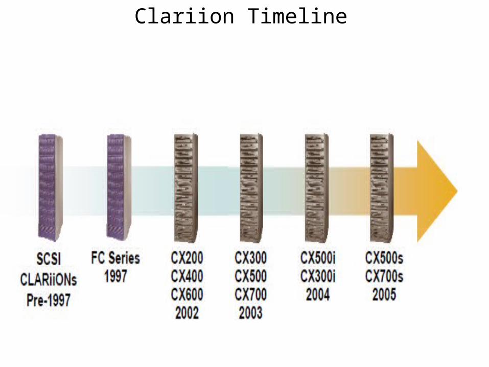
Clariion Timeline
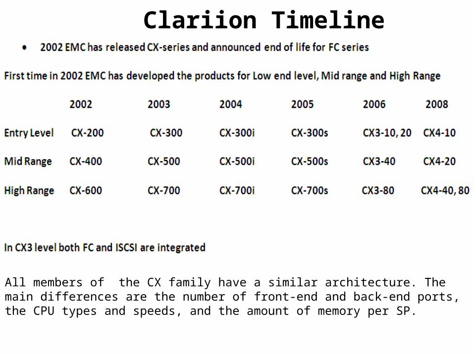
Clariion Timeline
All members of the CX family have a similar architecture. The main differences are the number of front-end and back-end ports, the CPU types and speeds, and the amount of memory per SP.
Clariion Hardware
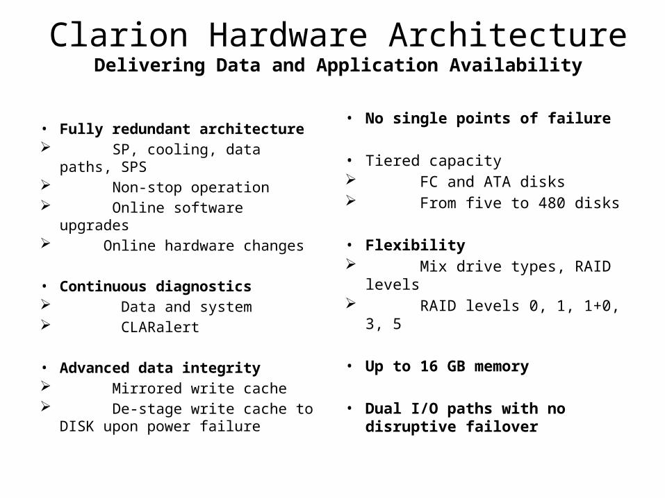
Clarion Hardware ArchitectureDelivering Data and Application Availability
• Fully redundant architecture SP, cooling, data paths, SPS Non-stop operation Online software upgrades Online hardware changes
• Continuous diagnostics Data and system CLARalert
• Advanced data integrity Mirrored write cache De-stage write cache to DISK
upon power failure
• No single points of failure
• Tiered capacity FC and ATA disks From five to 480 disks
• Flexibility Mix drive types, RAID levels RAID levels 0, 1, 1+0, 3, 5
• Up to 16 GB memory
• Dual I/O paths with no disruptive failover
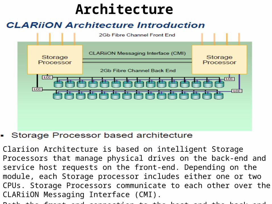
Clariion Architecture
Clariion Architecture is based on intelligent Storage Processors that manage physical drives on the back-end and service host requests on the front-end. Depending on the module, each Storage processor includes either one or two CPUs. Storage Processors communicate to each other over the CLARiiON Messaging Interface (CMI).Both the front-end connection to the host and the back-end connection to the physical storage are 2Gb/4GB Fibre channel
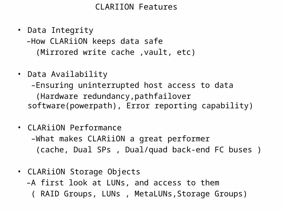
CLARIION Features
• Data Integrity –How CLARiiON keeps data safe (Mirrored write cache ,vault, etc)
• Data Availability –Ensuring uninterrupted host access to data (Hardware redundancy,pathfailover software(powerpath), Error reporting
capability)
• CLARiiON Performance –What makes CLARiiON a great performer (cache, Dual SPs , Dual/quad back-end FC buses )
• CLARiiON Storage Objects –A first look at LUNs, and access to them ( RAID Groups, LUNs , MetaLUNs,Storage Groups)
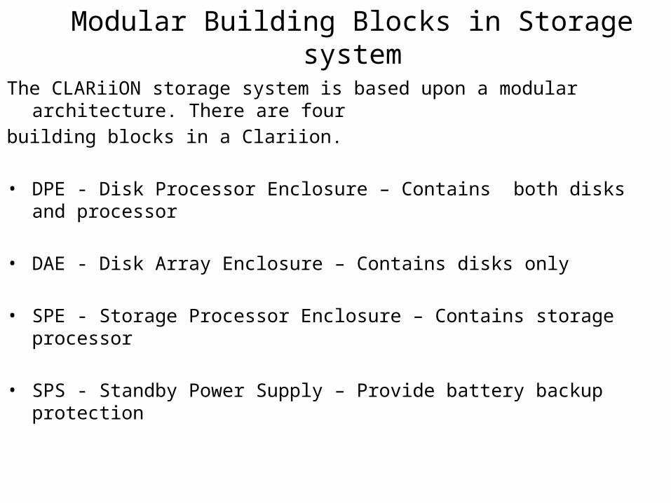
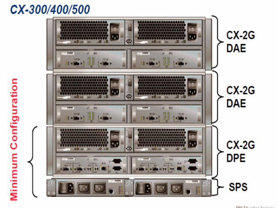
Modular Building Blocks in Storage systemThe CLARiiON storage system is based upon a modular architecture. There are fourbuilding blocks in a Clariion.
• DPE - Disk Processor Enclosure – Contains both disks and processor
• DAE - Disk Array Enclosure – Contains disks only
• SPE - Storage Processor Enclosure – Contains storage processor
• SPS - Standby Power Supply – Provide battery backup protection
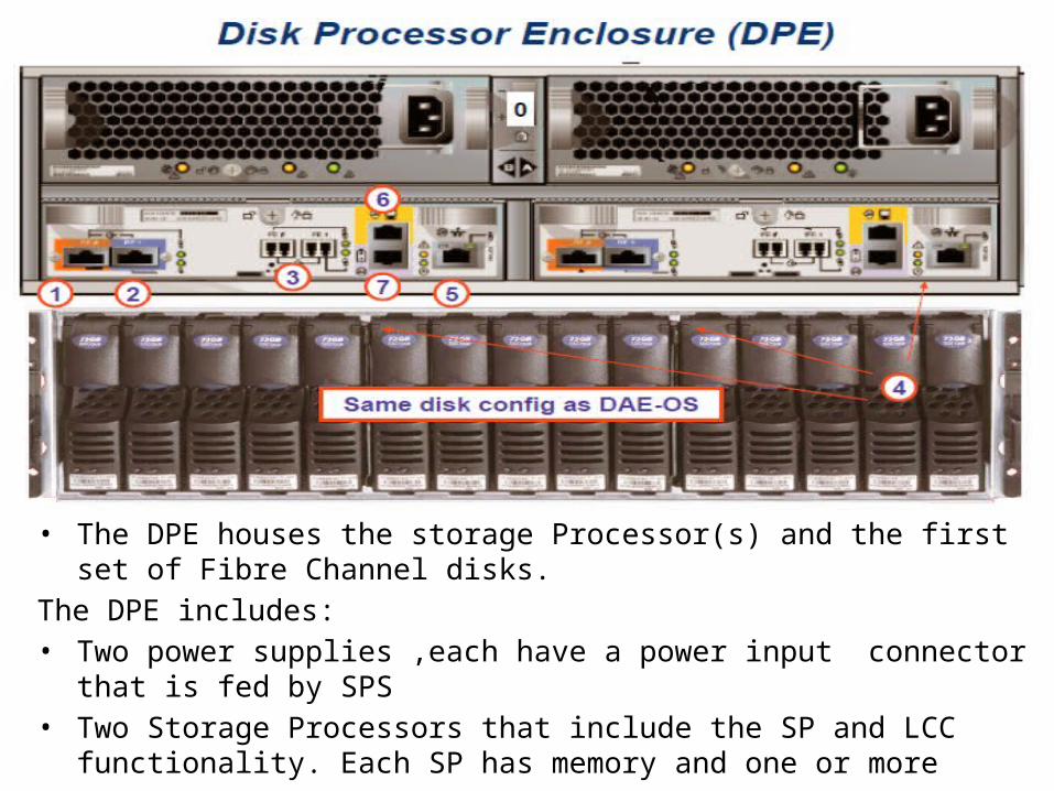
• The DPE houses the storage Processor(s) and the first set of Fibre Channel disks.The DPE includes:• Two power supplies ,each have a power input connector that is fed by SPS• Two Storage Processors that include the SP and LCC functionality. Each SP has
memory and one or more processors.• Backend ports , Frontend Ports ,Serial port and Ethernet Management port
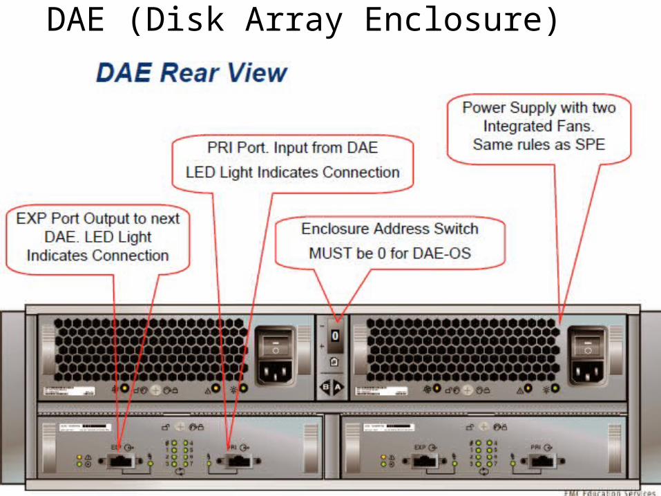
DAE (Disk Array Enclosure)
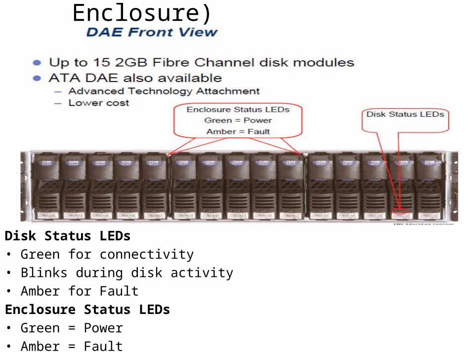
Disk Status LEDs• Green for connectivity• Blinks during disk activity• Amber for FaultEnclosure Status LEDs• Green = Power• Amber = Fault
DAE (Disk Array Enclosure)
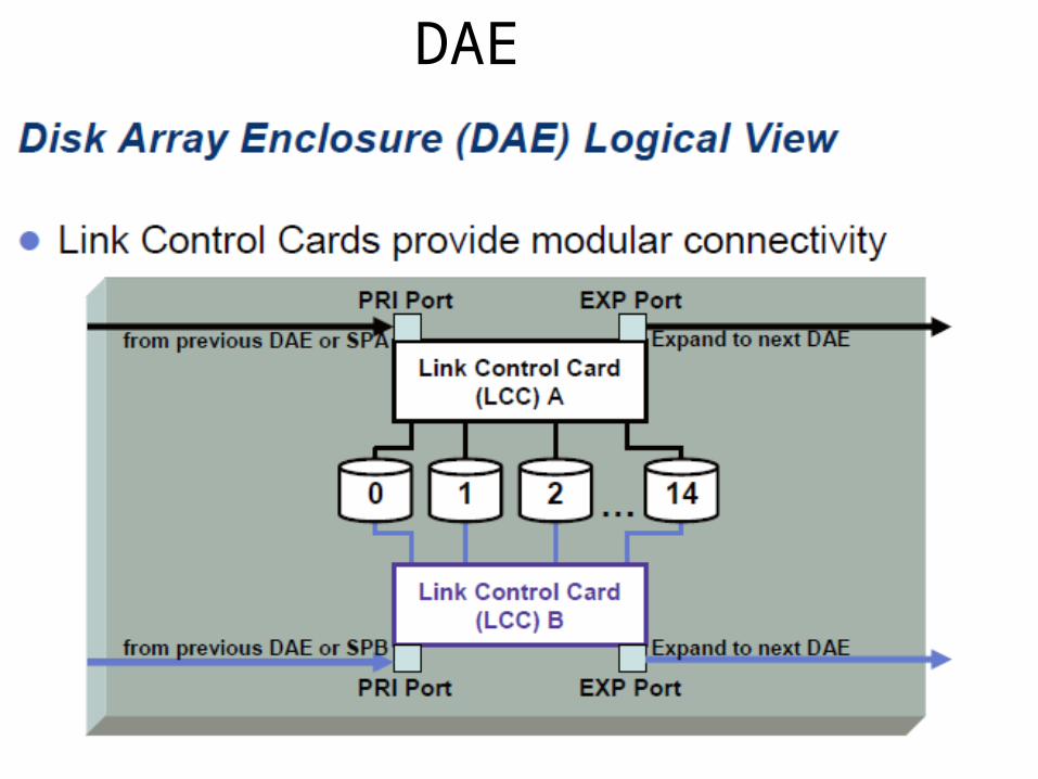
DAE
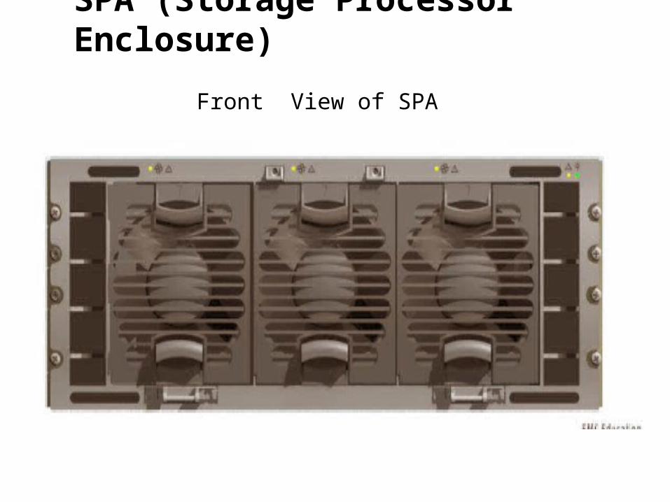
SPA (Storage Processor Enclosure)
Front View of SPA
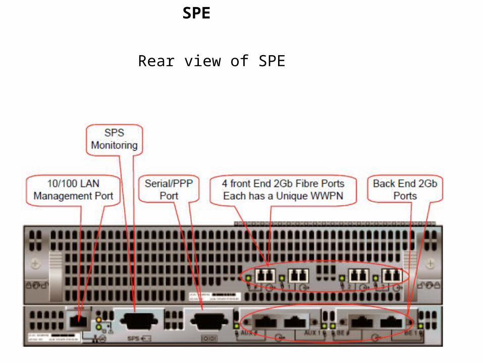
SPE
Rear view of SPE
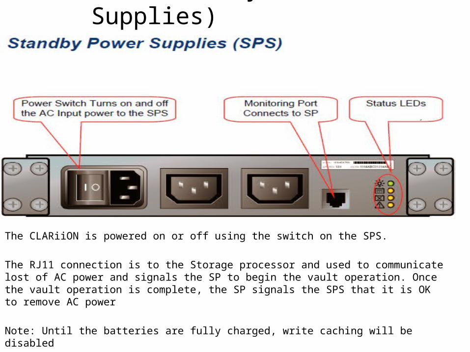
SPS (Standby Power Supplies)
The CLARiiON is powered on or off using the switch on the SPS.
The RJ11 connection is to the Storage processor and used to communicate lost of AC power and signals the SP to begin the vault operation. Once the vault operation is complete, the SP signals the SPS that it is OK to remove AC power
Note: Until the batteries are fully charged, write caching will be disabled
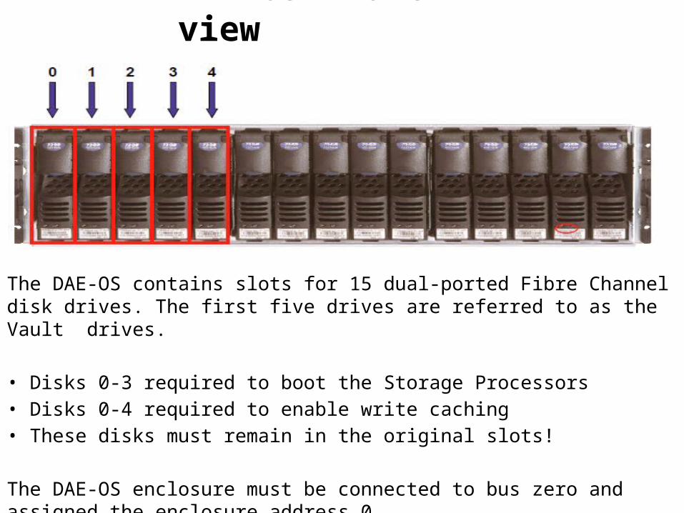
DAE-OS Front view
The DAE-OS contains slots for 15 dual-ported Fibre Channel disk drives. The first five drives are referred to as the Vault drives.
• Disks 0-3 required to boot the Storage Processors• Disks 0-4 required to enable write caching • These disks must remain in the original slots!
The DAE-OS enclosure must be connected to bus zero and assigned the enclosure address 0.
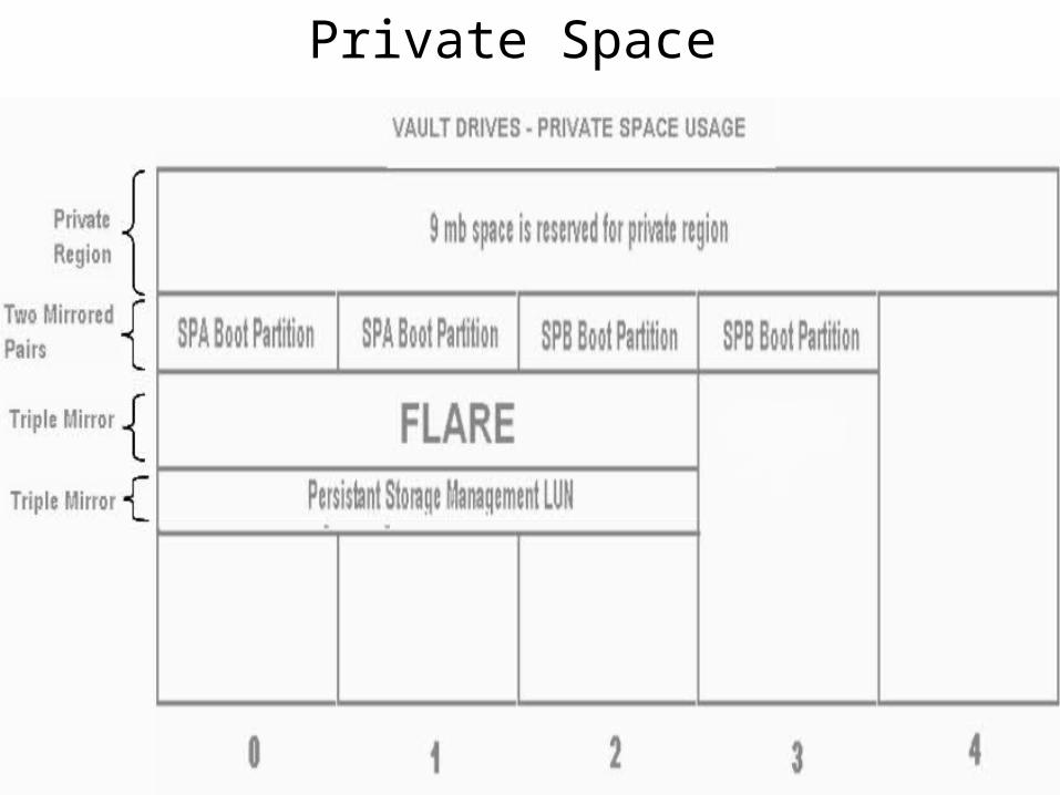
Private Space
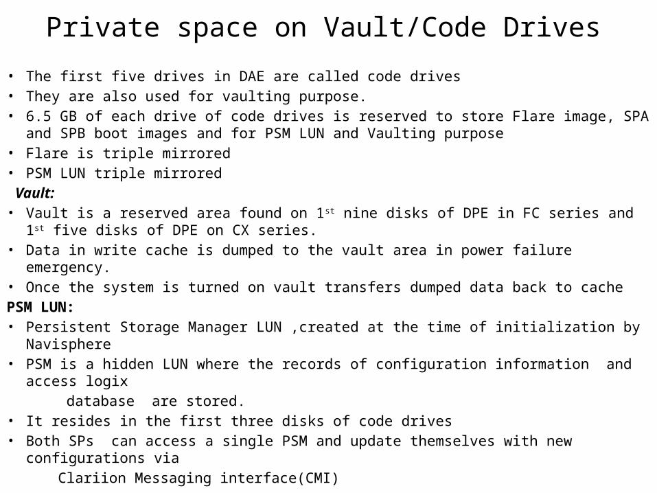
Private space on Vault/Code Drives• The first five drives in DAE are called code drives• They are also used for vaulting purpose.• 6.5 GB of each drive of code drives is reserved to store Flare image, SPA and SPB boot
images and for PSM LUN and Vaulting purpose• Flare is triple mirrored • PSM LUN triple mirrored Vault:• Vault is a reserved area found on 1st nine disks of DPE in FC series and 1st five disks of DPE
on CX series.• Data in write cache is dumped to the vault area in power failure emergency.• Once the system is turned on vault transfers dumped data back to cache PSM LUN:• Persistent Storage Manager LUN ,created at the time of initialization by Navisphere • PSM is a hidden LUN where the records of configuration information and access logix database are stored.• It resides in the first three disks of code drives • Both SPs can access a single PSM and update themselves with new configurations via Clariion Messaging interface(CMI)
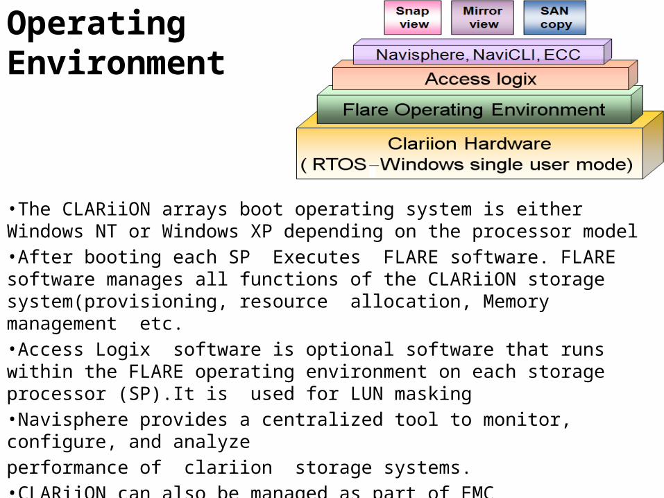
Clariion Operating Environment
•The CLARiiON arrays boot operating system is either Windows NT or Windows XP depending on the processor model•After booting each SP Executes FLARE software. FLARE software manages all functions of the CLARiiON storage system(provisioning, resource allocation, Memory management etc.•Access Logix software is optional software that runs within the FLARE operating environment on each storage processor (SP).It is used for LUN masking•Navisphere provides a centralized tool to monitor, configure, and analyze performance of clariion storage systems. •CLARiiON can also be managed as part of EMC ControlCenter, allowing full end-to-end management.•Other array software includes SnapView, MirrorView, and SANCopy.
Clariion Management
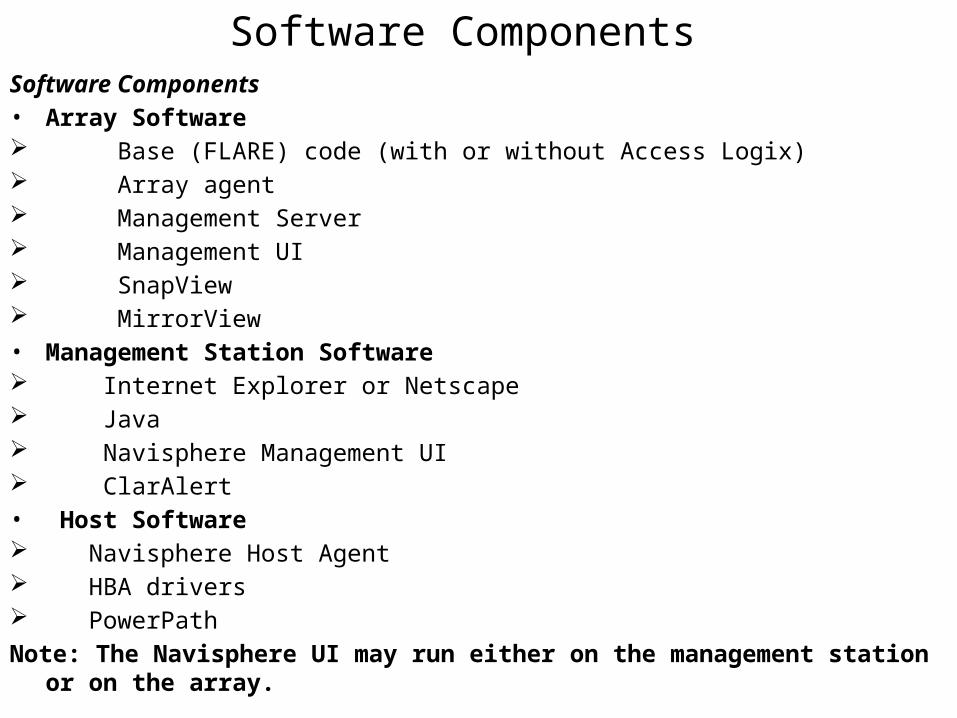
Software ComponentsSoftware Components• Array Software Base (FLARE) code (with or without Access Logix) Array agent Management Server Management UI SnapView MirrorView• Management Station Software Internet Explorer or Netscape Java Navisphere Management UI ClarAlert• Host Software Navisphere Host Agent HBA drivers PowerPathNote: The Navisphere UI may run either on the management station or on the array.
Navisphere Users
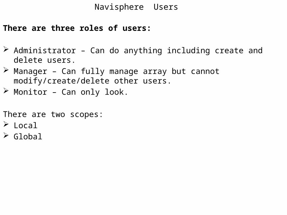
There are three roles of users:
Administrator – Can do anything including create and delete users. Manager – Can fully manage array but cannot modify/create/delete other users. Monitor – Can only look.
There are two scopes: Local Global
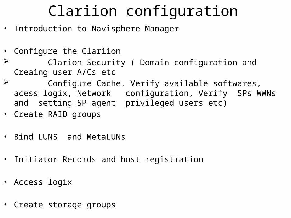
Clariion configuration• Introduction to Navisphere Manager
• Configure the Clariion Clarion Security ( Domain configuration and Creaing user A/Cs etc Configure Cache, Verify available softwares, acess logix, Network
configuration, Verify SPs WWNs and setting SP agent privileged users etc)• Create RAID groups
• Bind LUNS and MetaLUNs
• Initiator Records and host registration
• Access logix
• Create storage groups
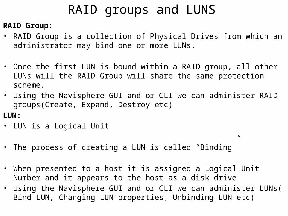
RAID groups and LUNSRAID Group:• RAID Group is a collection of Physical Drives from which an administrator may bind
one or more LUNs.
• Once the first LUN is bound within a RAID group, all other LUNs will the RAID Group will share the same protection scheme.
• Using the Navisphere GUI and or CLI we can administer RAID groups(Create, Expand, Destroy etc)
LUN:• LUN is a Logical Unit
• The process of creating a LUN is called “Binding”
• When presented to a host it is assigned a Logical Unit Number and it appears to the host as a disk drive
• Using the Navisphere GUI and or CLI we can administer LUNs( Bind LUN, Changing LUN properties, Unbinding LUN etc)
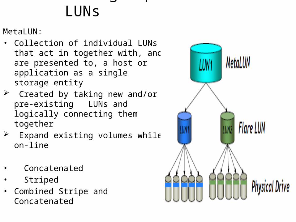
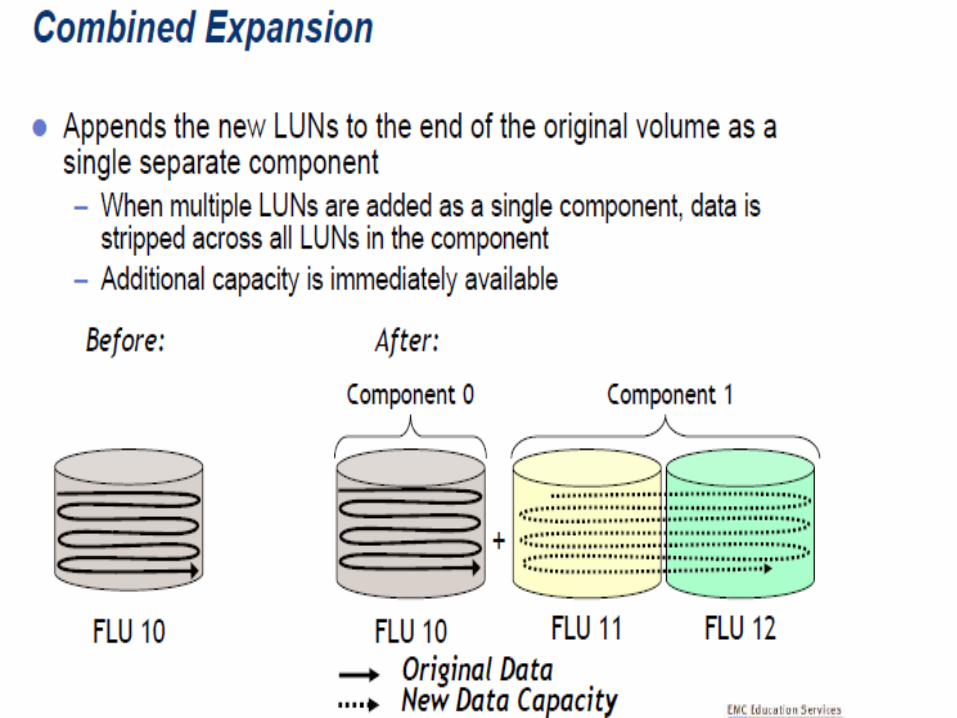
RAID groups and LUNsMetaLUN:• Collection of individual LUNs that act in
together with, and are presented to, a host or application as a single storage entity
Created by taking new and/or pre-existing LUNs and logically connecting them together
Expand existing volumes while on-line
• Concatenated• Striped• Combined Stripe and Concatenated
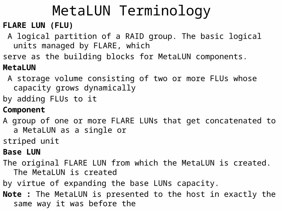
MetaLUN TerminologyFLARE LUN (FLU) A logical partition of a RAID group. The basic logical units managed by FLARE, whichserve as the building blocks for MetaLUN components.MetaLUN A storage volume consisting of two or more FLUs whose capacity grows dynamicallyby adding FLUs to itComponentA group of one or more FLARE LUNs that get concatenated to a MetaLUN as a single orstriped unitBase LUNThe original FLARE LUN from which the MetaLUN is created. The MetaLUN is createdby virtue of expanding the base LUNs capacity.Note : The MetaLUN is presented to the host in exactly the same way it was before theexpansion – i.e. the Name, LUN ID, SCIS ID, and WWN is the same. The only thing thatchanged is the capacity is increased.To Expand a LUN, right click on the LUN and select Expand… This invokes the StorageWizard
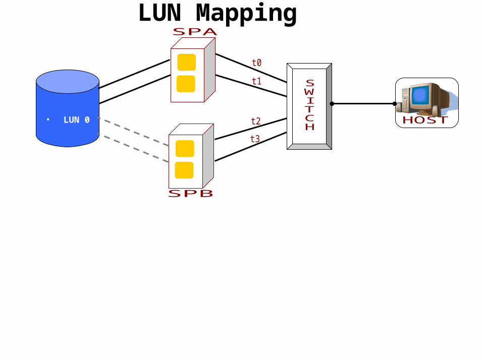
LUN Mapping
• LUN 0
Access Logix
Access Logix• What Access Logix is • Why Access Logix is needed • Configuring Access Logix • Storage Groups • Configuring Storage Groups
Access Logix
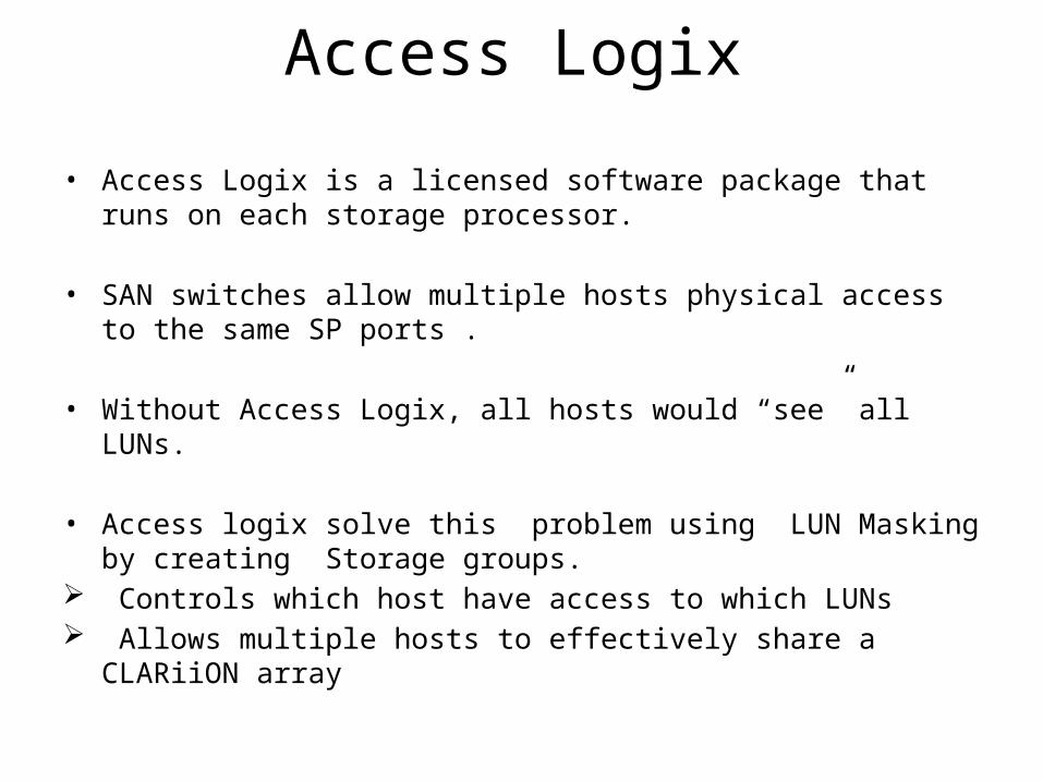
• Access Logix is a licensed software package that runs on each storage processor.
• SAN switches allow multiple hosts physical access to the same SP ports .
• Without Access Logix, all hosts would “see” all LUNs.
• Access logix solve this problem using LUN Masking by creating Storage groups.
Controls which host have access to which LUNs Allows multiple hosts to effectively share a CLARiiON array
Manual and Auto Registration
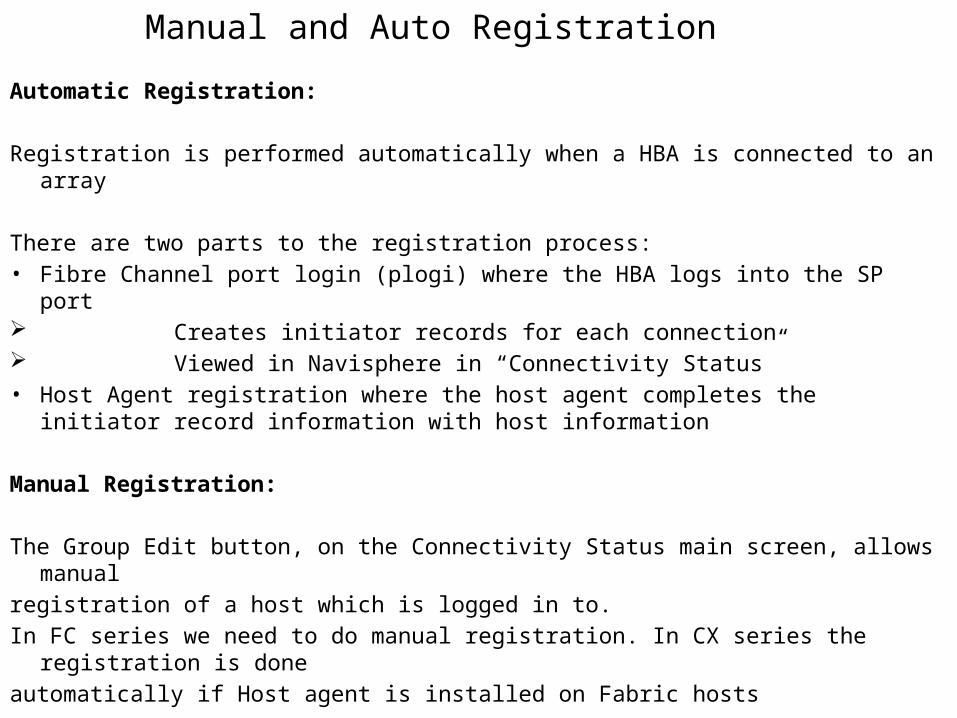
Automatic Registration:
Registration is performed automatically when a HBA is connected to an array
There are two parts to the registration process:• Fibre Channel port login (plogi) where the HBA logs into the SP port Creates initiator records for each connection Viewed in Navisphere in “Connectivity Status”• Host Agent registration where the host agent completes the initiator record
information with host information
Manual Registration:
The Group Edit button, on the Connectivity Status main screen, allows manualregistration of a host which is logged in to.In FC series we need to do manual registration. In CX series the registration is doneautomatically if Host agent is installed on Fabric hosts
Storage Groups• Managing Storage Groups• Creating Storage Groups • Viewing and changing Storage Group properties • Adding and removing LUNs • Connecting and disconnecting hosts • Destroying Storage Groups
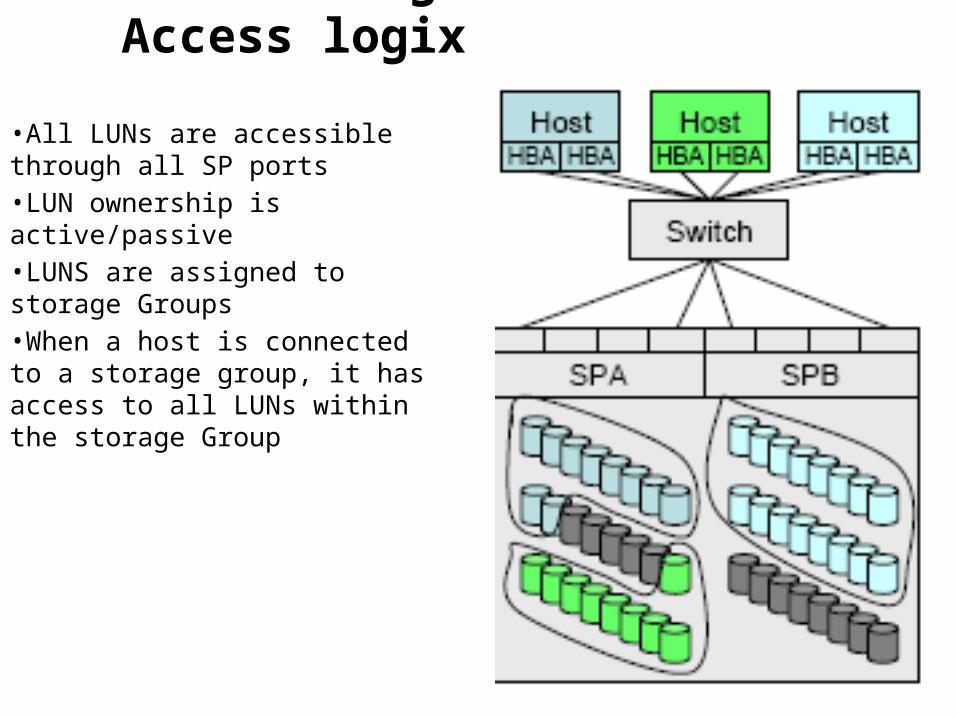
LUN Masking with Access logix
•All LUNs are accessible through all SP ports•LUN ownership is active/passive•LUNS are assigned to storage Groups•When a host is connected to a storage group, it has access to all LUNs within the storage Group
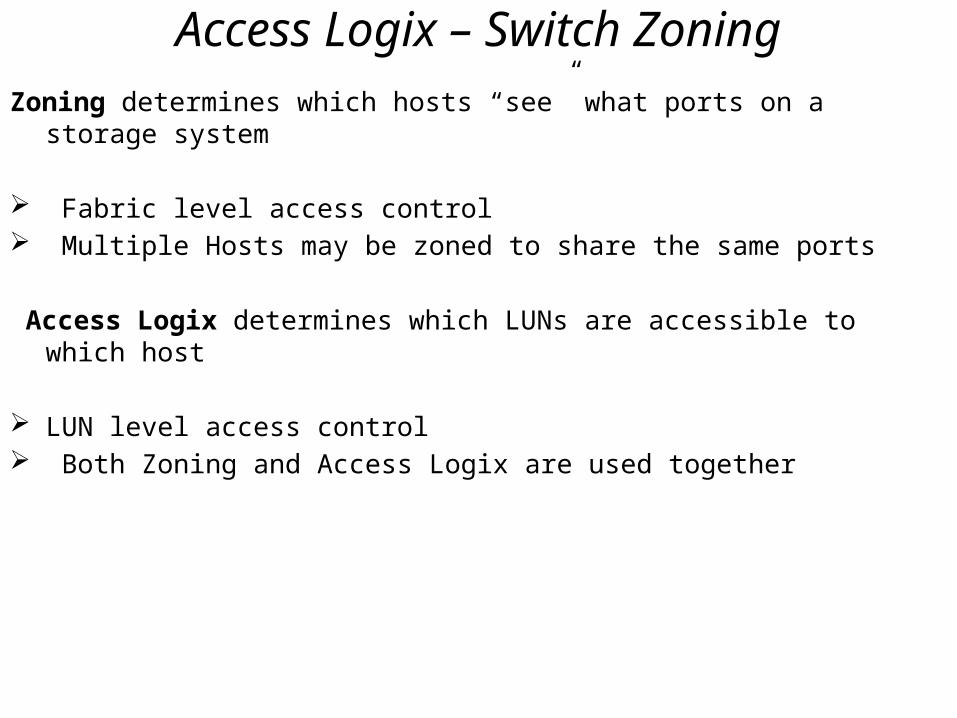
Access Logix – Switch ZoningZoning determines which hosts “see” what ports on a storage system
Fabric level access control Multiple Hosts may be zoned to share the same ports
Access Logix determines which LUNs are accessible to which host
LUN level access control Both Zoning and Access Logix are used together
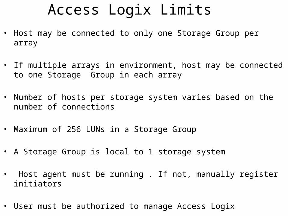
Access Logix Limits• Host may be connected to only one Storage Group per array
• If multiple arrays in environment, host may be connected to one Storage Group in each array
• Number of hosts per storage system varies based on the number of connections
• Maximum of 256 LUNs in a Storage Group
• A Storage Group is local to 1 storage system
• Host agent must be running . If not, manually register initiators
• User must be authorized to manage Access Logix
Power path
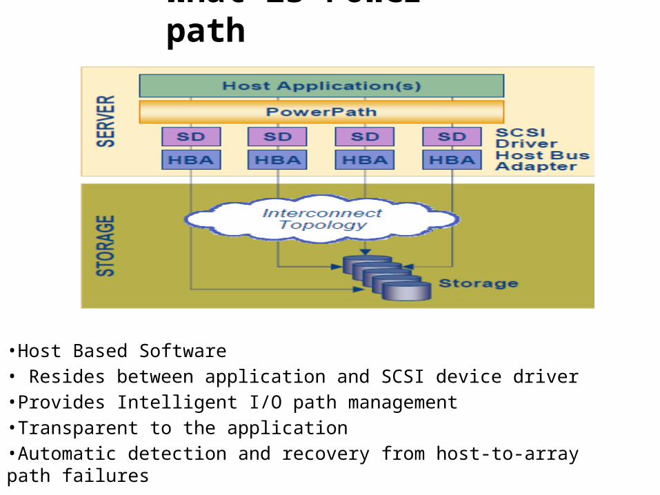
What is Power path
•Host Based Software• Resides between application and SCSI device driver•Provides Intelligent I/O path management•Transparent to the application•Automatic detection and recovery from host-to-array path failures
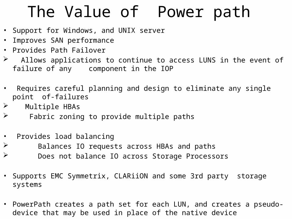
The Value of Power path• Support for Windows, and UNIX server• Improves SAN performance• Provides Path Failover Allows applications to continue to access LUNS in the event of failure of any
component in the IOP
• Requires careful planning and design to eliminate any single point of-failures Multiple HBAs Fabric zoning to provide multiple paths
• Provides load balancing Balances IO requests across HBAs and paths Does not balance IO across Storage Processors
• Supports EMC Symmetrix, CLARiiON and some 3rd party storage systems
• PowerPath creates a path set for each LUN, and creates a pseudo-device that may be used in place of the native device
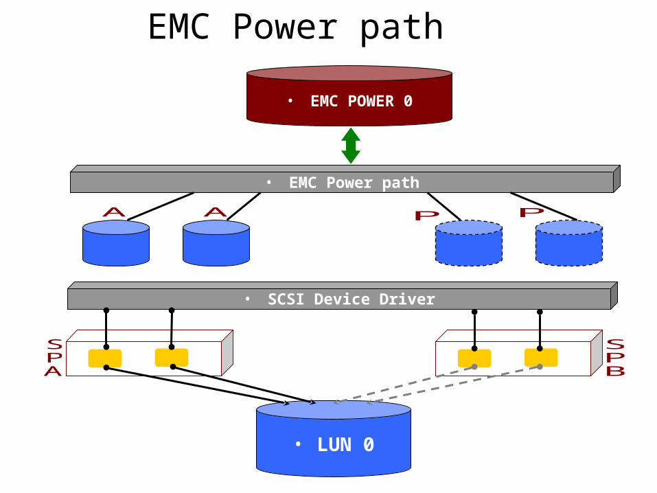
EMC Power path
• SCSI Device Driver
• LUN 0
• EMC Power path
• EMC POWER 0
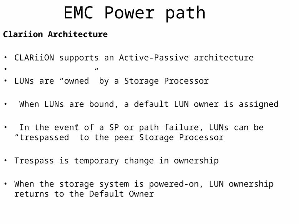
EMC Power pathClariion Architecture
• CLARiiON supports an Active-Passive architecture• • LUNs are “owned” by a Storage Processor
• When LUNs are bound, a default LUN owner is assigned
• In the event of a SP or path failure, LUNs can be “trespassed” to the peer Storage Processor
• Trespass is temporary change in ownership
• When the storage system is powered-on, LUN ownership returns to the Default Owner
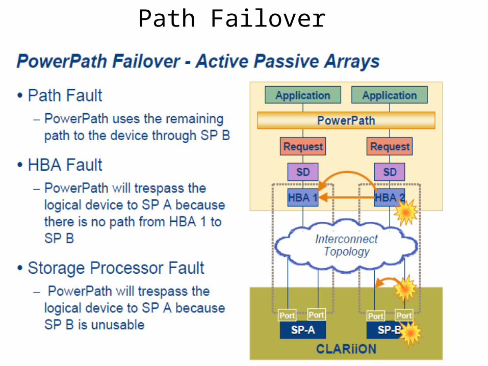
Path Failover
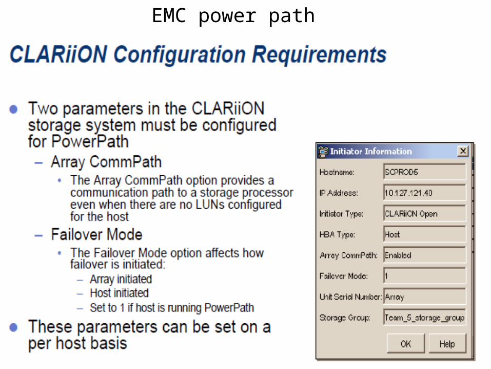
EMC power path

Power Path AdministrationPower path settings on Clariion for each host:Tools Failover setup wizard(Enable Array coman path and set Failover mode as 1 for power path.Power Path Administration provides both GUI(windows) and CLI (All platforms)CLI Administration:1.Install Power path pkg on Hosts2. Update PATH variable with /etc extension for all powerpath cmds to work3.Add power path License:# /etc/emcpreg -add “License Key”# /etc/emcpreg –list – to list the installed power path license details4. To verify that PowerPath devices are configured on the host:# powermt display dev=all5. To Configure any missing logical devices.#powermt config6. To remove dead paths#powermt check7. Powermt restore – To restore dead paths after have been repaired
Clariion Applications
Clariion Applications• Snapview Snapshots• Snapview Clones• Mirror Copy
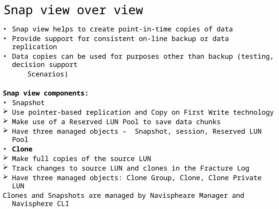
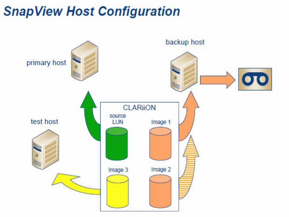
Snap view over view• Snap view helps to create point-in-time copies of data• Provide support for consistent on-line backup or data replication • Data copies can be used for purposes other than backup (testing, decision support Scenarios)
Snap view components:• Snapshot Use pointer-based replication and Copy on First Write technology Make use of a Reserved LUN Pool to save data chunks Have three managed objects – Snapshot, session, Reserved LUN Pool • Clone Make full copies of the source LUN Track changes to source LUN and clones in the Fracture Log Have three managed objects: Clone Group, Clone, Clone Private LUN Clones and Snapshots are managed by Navispheare Manager and Navisphere CLI
Snapview Snapshots
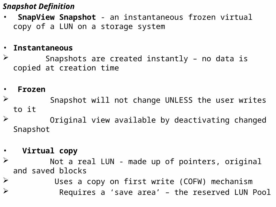
Snapshot Definition• SnapView Snapshot - an instantaneous frozen virtual copy of a LUN on a storage
system
• Instantaneous Snapshots are created instantly – no data is copied at creation time
• Frozen Snapshot will not change UNLESS the user writes to it Original view available by deactivating changed Snapshot
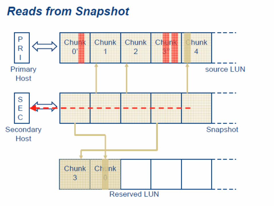
• Virtual copy Not a real LUN - made up of pointers, original and saved blocks Uses a copy on first write (COFW) mechanism Requires a ‘save area’ – the reserved LUN Pool
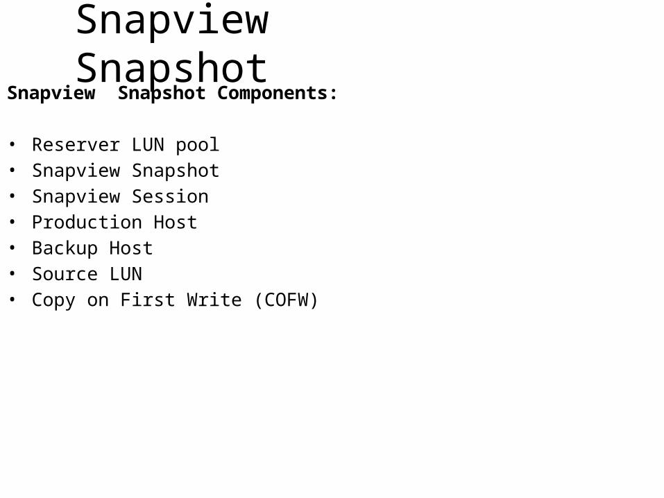
Snapview SnapshotSnapview Snapshot Components:
• Reserver LUN pool• Snapview Snapshot• Snapview Session• Production Host• Backup Host• Source LUN• Copy on First Write (COFW)
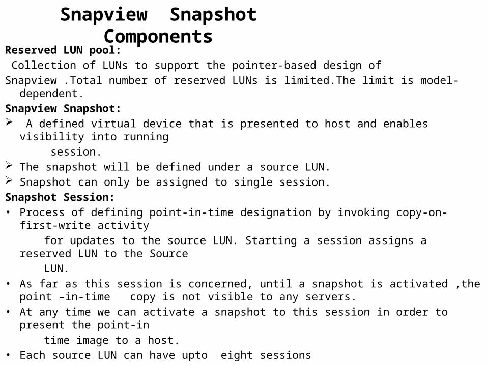
Snapview Snapshot ComponentsReserved LUN pool: Collection of LUNs to support the pointer-based design ofSnapview .Total number of reserved LUNs is limited.The limit is model-dependent.Snapview Snapshot: A defined virtual device that is presented to host and enables visibility into running session. The snapshot will be defined under a source LUN. Snapshot can only be assigned to single session.Snapshot Session:• Process of defining point-in-time designation by invoking copy-on-first-write activity for updates to the source LUN. Starting a session assigns a reserved LUN to the
Source LUN. • As far as this session is concerned, until a snapshot is activated ,the point –in-time
copy is not visible to any servers.• At any time we can activate a snapshot to this session in order to present the point-in time image to a host.• Each source LUN can have upto eight sessions
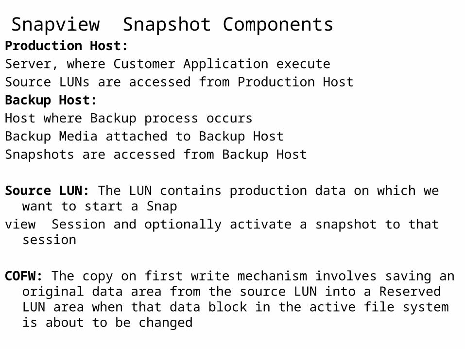
Snapview Snapshot ComponentsProduction Host: Server, where Customer Application executeSource LUNs are accessed from Production HostBackup Host: Host where Backup process occursBackup Media attached to Backup HostSnapshots are accessed from Backup Host
Source LUN: The LUN contains production data on which we want to start a Snapview Session and optionally activate a snapshot to that session
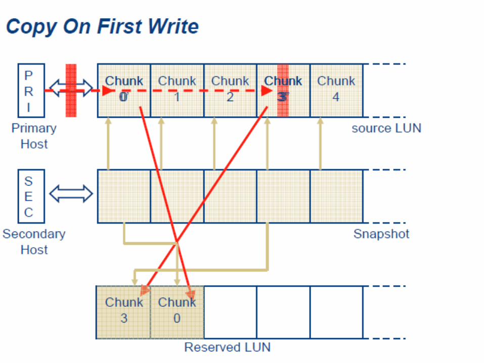
COFW: The copy on first write mechanism involves saving an original data area from the source LUN into a Reserved LUN area when that data block in the active file system is about to be changed
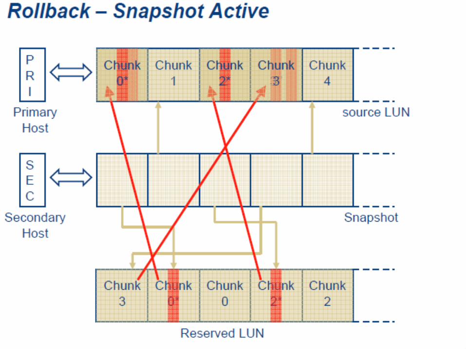
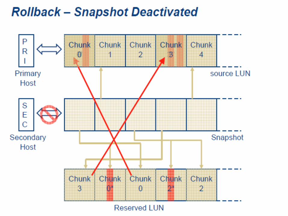
Rollback: Enables recovery of the source LUN by copying data in the reserved LUN back to the Source LUN
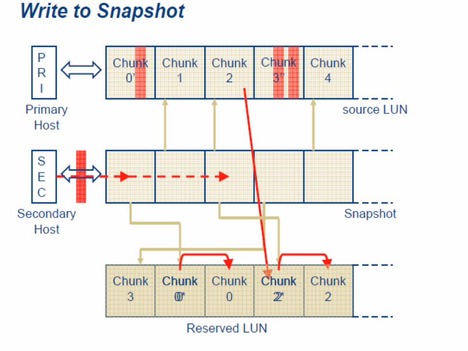
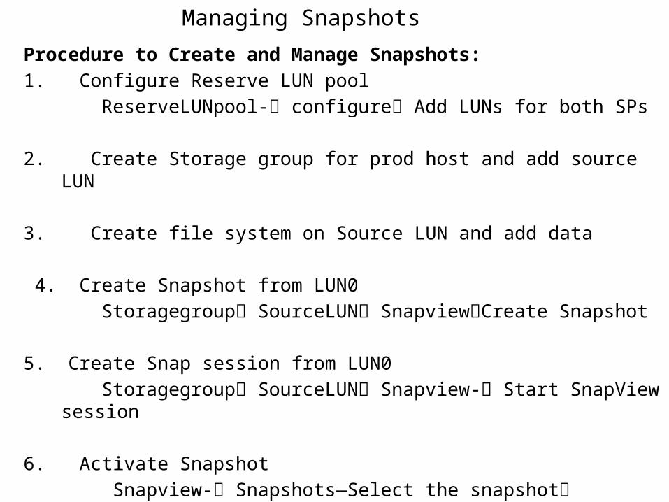
Managing SnapshotsProcedure to Create and Manage Snapshots:1. Configure Reserve LUN pool ReserveLUNpool- configure Add LUNs for both SPs
2. Create Storage group for prod host and add source LUN
3. Create file system on Source LUN and add data
4. Create Snapshot from LUN0 Storagegroup SourceLUN SnapviewCreate Snapshot 5. Create Snap session from LUN0 Storagegroup SourceLUN Snapview- Start SnapView session 6. Activate Snapshot Snapview- Snapshots—Select the snapshot Activate Snapshot (Select a session for that snapshot)
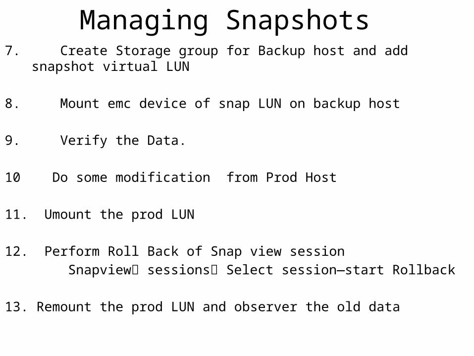
Managing Snapshots7. Create Storage group for Backup host and add snapshot virtual LUN
8. Mount emc device of snap LUN on backup host
9. Verify the Data.
10 Do some modification from Prod Host 11. Umount the prod LUN 12. Perform Roll Back of Snap view session Snapview sessions Select session—start Rollback 13. Remount the prod LUN and observer the old data
Snapview Clones
SNAP view Clone
SnapView Clones - Overview• SnapView Clone – a full copy of a LUN internal to a storage system.
• Clones take time to populate (synchronize)
• Clone is independent of the Source once synchronization is complete
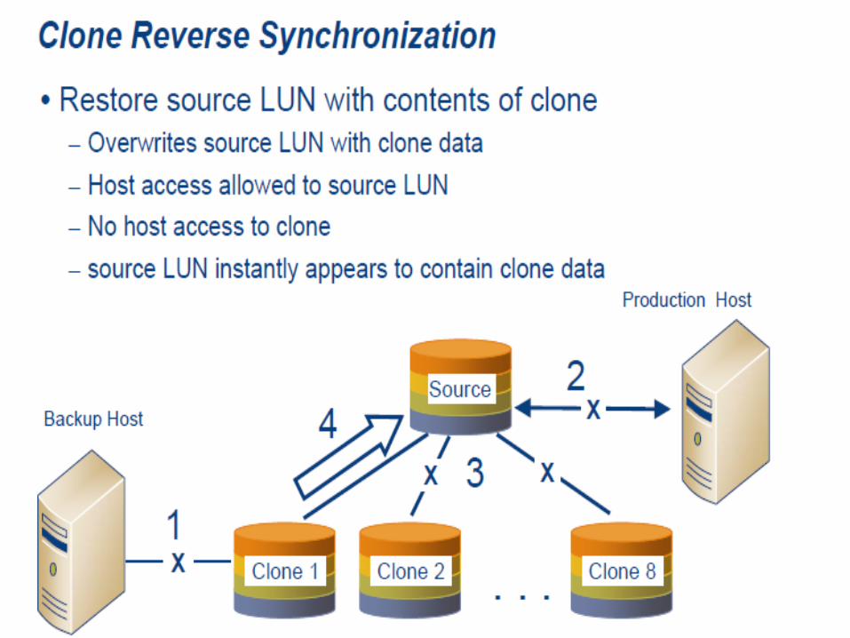
• 2-way synchronization – Clones may be incrementally updated from the source LUN – source LUNs may be incrementally updated from a clone
• Clone must be EXACTLY the same size as source LUN
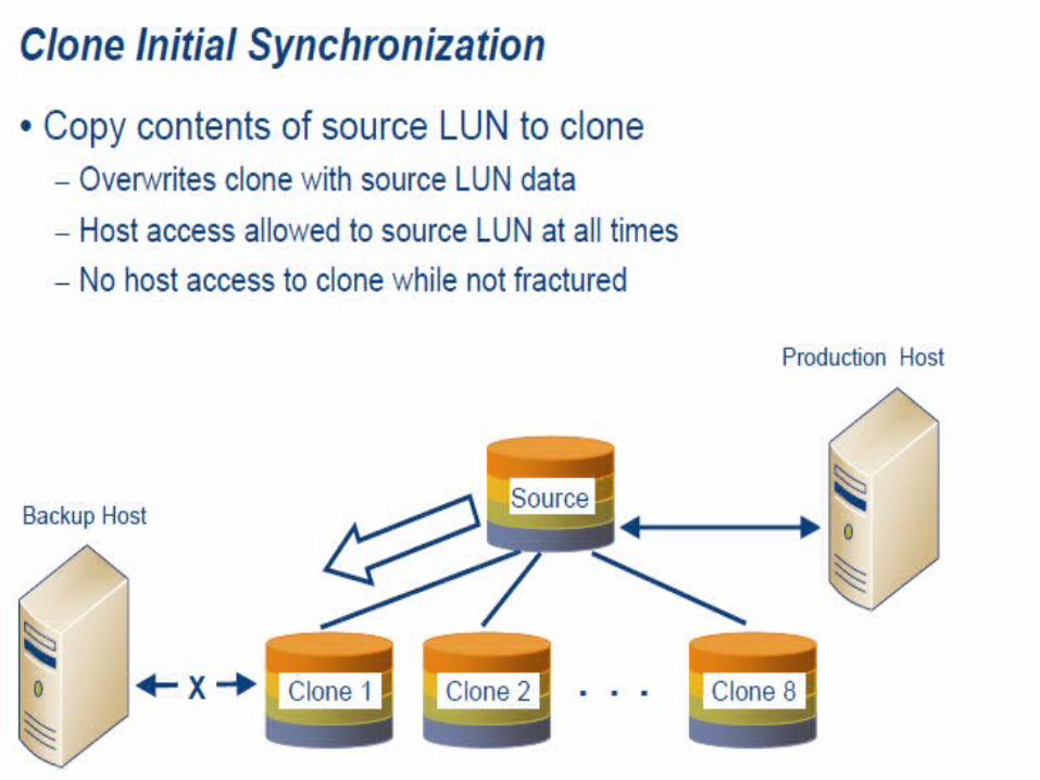
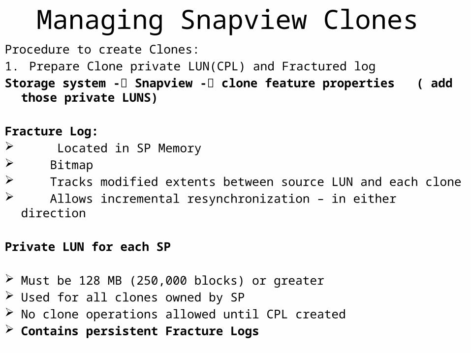
Managing Snapview ClonesProcedure to create Clones:1. Prepare Clone private LUN(CPL) and Fractured logStorage system - Snapview - clone feature properties ( add those private LUNS)
Fracture Log: Located in SP Memory Bitmap Tracks modified extents between source LUN and each clone Allows incremental resynchronization – in either direction
Private LUN for each SP
Must be 128 MB (250,000 blocks) or greater Used for all clones owned by SP No clone operations allowed until CPL created Contains persistent Fracture Logs
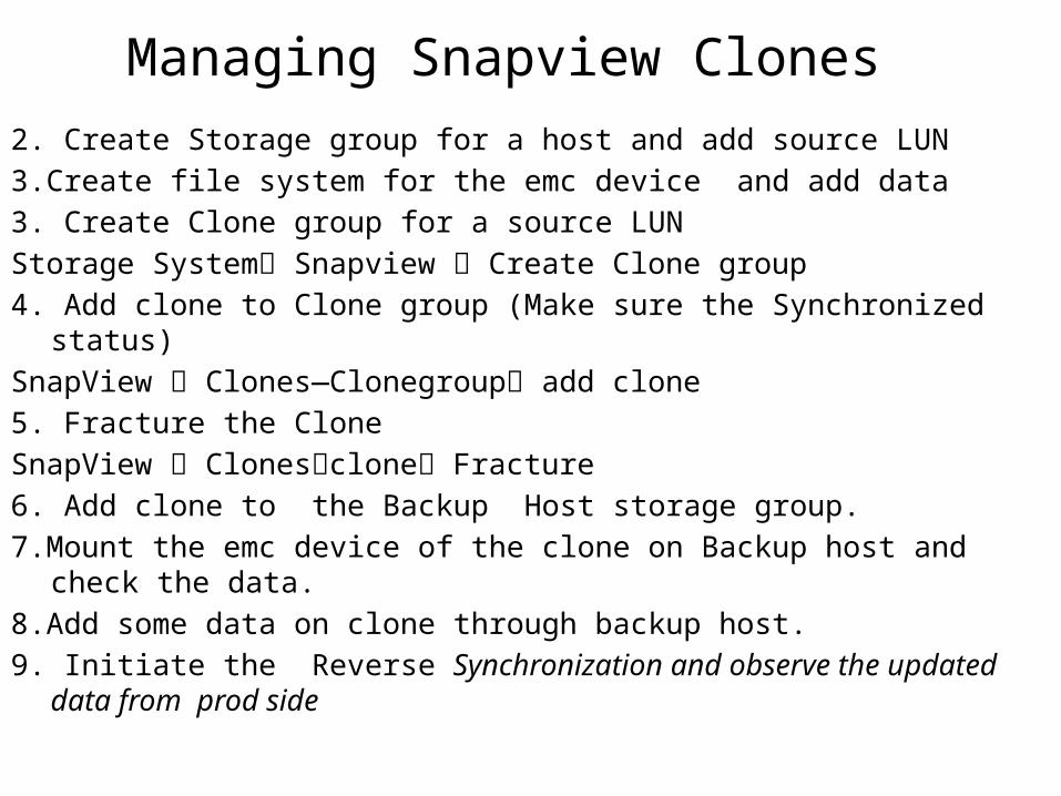
Managing Snapview Clones2. Create Storage group for a host and add source LUN3.Create file system for the emc device and add data 3. Create Clone group for a source LUNStorage System Snapview Create Clone group 4. Add clone to Clone group (Make sure the Synchronized status)SnapView Clones—Clonegroup add clone5. Fracture the CloneSnapView Clonesclone Fracture6. Add clone to the Backup Host storage group. 7.Mount the emc device of the clone on Backup host and check the data.8.Add some data on clone through backup host.9. Initiate the Reverse Synchronization and observe the updated data from prod side

Mirror Copy
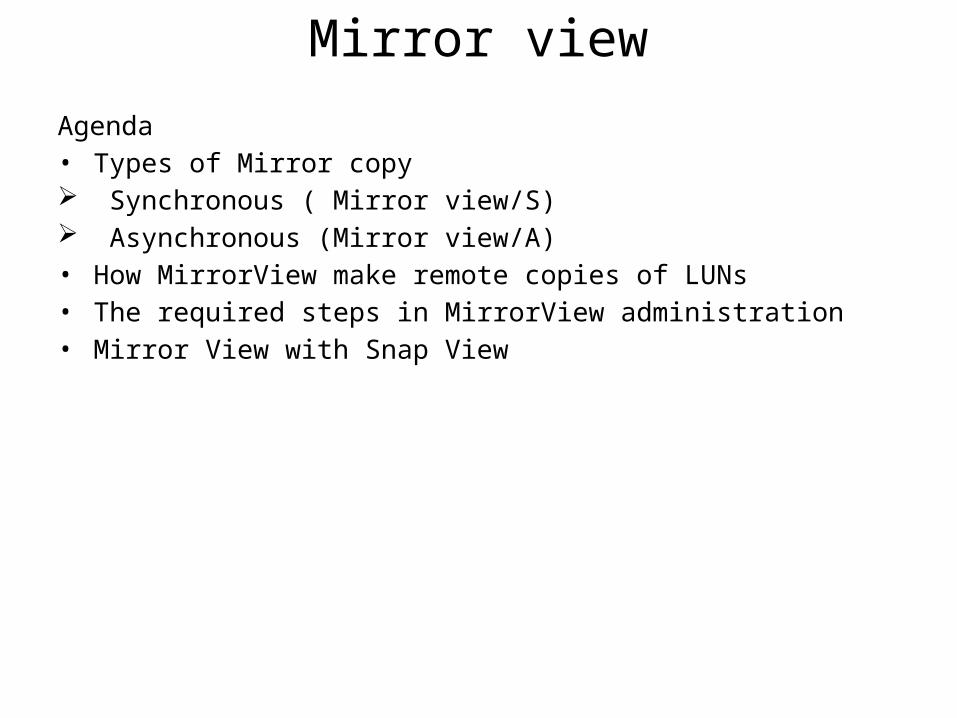
Mirror viewAgenda• Types of Mirror copy Synchronous ( Mirror view/S) Asynchronous (Mirror view/A)• How MirrorView make remote copies of LUNs• The required steps in MirrorView administration• Mirror View with Snap View
Mirror Copy overview• Optional storage system-based software
• This product is designed as storage system-based disaster-recovery(DR) solutions for mirroring local production data to a remote/disaster recovery site.
• Mirrorview/S is a sysnchronous product that mirrors data between local and remote storage systems
• Mirrorview/A is asynchronous product that offers extended-distance replication based on periodic incremental update model mirrors data
• Business requirements determine the structure of DR solution
• The buisiness will decide how much data loss is tolerable and how soon the data must be accessable again in the event of disaster.
Mirror copy overview It is a requirement that critical business information always be available. To protectthis information it is necessary for a DR plan to be in place to safe guard against anydisaster.
Recovery objects: Recovery objects are service levels that must be met to minimizethe loss of information and revenue in the event of disaster.The criticality of business application and information defines the recovery objectives.
The terms commonly used to define the recovery objectives are:
• Recovery point objective(RPO)• Recovery time objective(RTO)
Recovery point objective: • Recovery point objective defines the amount of acceptable data loss in the event of disaster. • RPO is typically expressed in duration of time.• Some applications may have zero tolerance for loss of data in the event of disaster. (Example: Financial Applications)
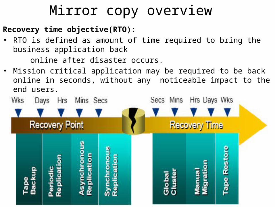
Mirror copy overviewRecovery time objective(RTO): • RTO is defined as amount of time required to bring the business application back online after disaster occurs. • Mission critical application may be required to be back online in seconds, without
any noticeable impact to the end users.
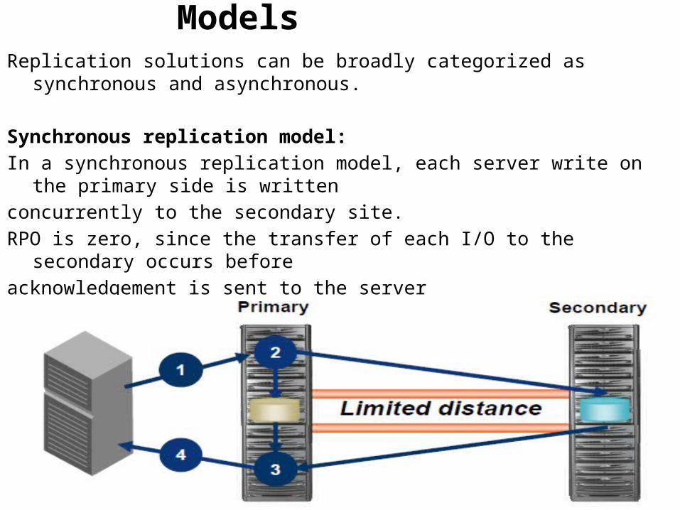
Replication ModelsReplication solutions can be broadly categorized as synchronous and asynchronous.
Synchronous replication model:In a synchronous replication model, each server write on the primary side is writtenconcurrently to the secondary site.RPO is zero, since the transfer of each I/O to the secondary occurs before acknowledgement is sent to the serverData at the secondary site is exactly the same as data at the primary site at the timeof disasterdisaster.
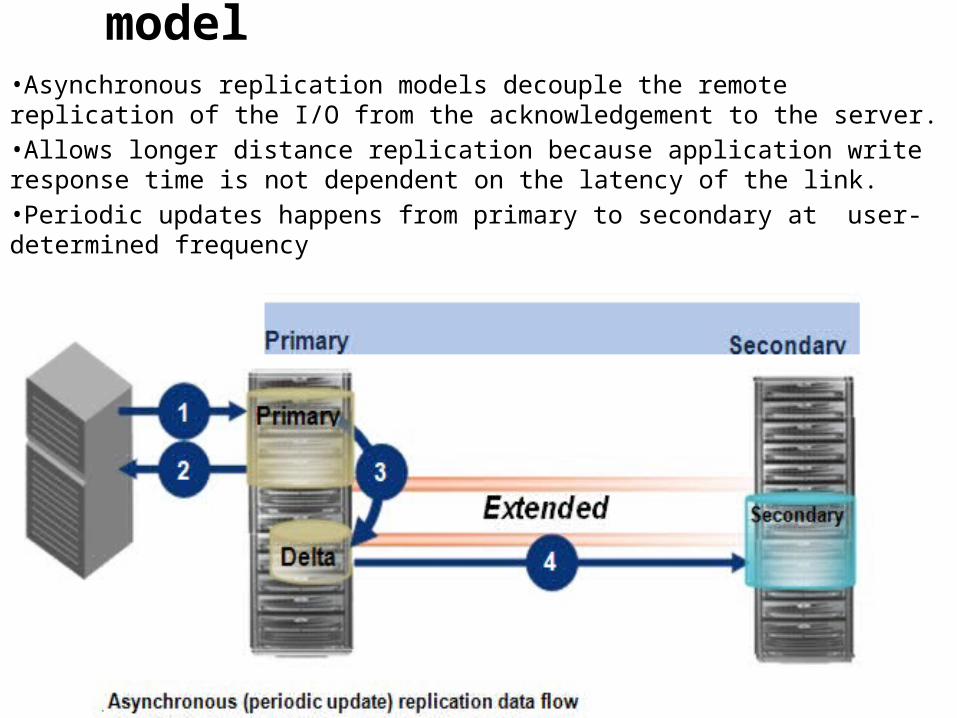
Asynchronous replication model •Asynchronous replication models decouple the remote replication of the I/O from the acknowledgement to the server. •Allows longer distance replication because application write response time is not dependent on the latency of the link.•Periodic updates happens from primary to secondary at user-determined frequency
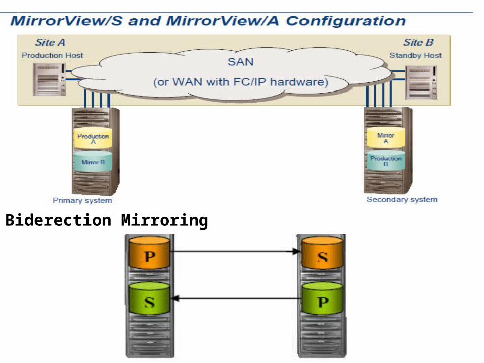
Biderection Mirroring
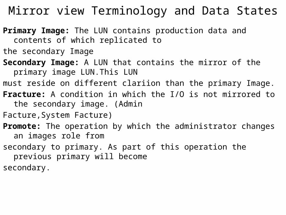
Mirror view Terminology and Data StatesPrimary Image: The LUN contains production data and contents of which replicated tothe secondary ImageSecondary Image: A LUN that contains the mirror of the primary image LUN.This LUNmust reside on different clariion than the primary Image.Fracture: A condition in which the I/O is not mirrored to the secondary image. (AdminFacture,System Facture)Promote: The operation by which the administrator changes an images role fromsecondary to primary. As part of this operation the previous primary will becomesecondary.
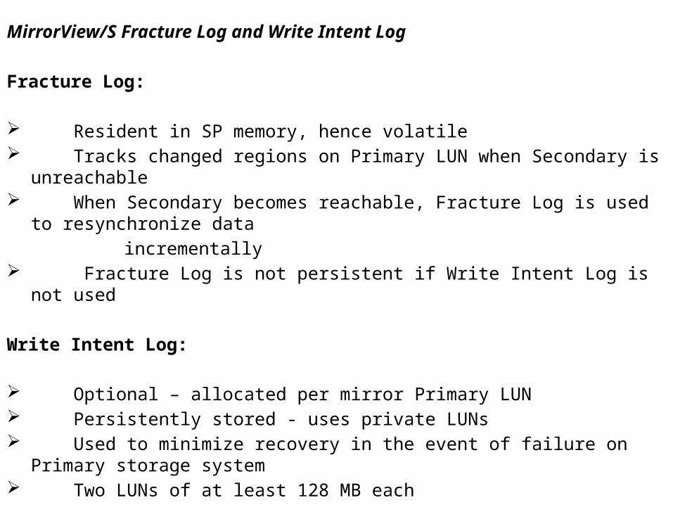
MirrorView/S Fracture Log and Write Intent Log
Fracture Log: Resident in SP memory, hence volatile Tracks changed regions on Primary LUN when Secondary is unreachable When Secondary becomes reachable, Fracture Log is used to resynchronize data incrementally Fracture Log is not persistent if Write Intent Log is not used
Write Intent Log: Optional – allocated per mirror Primary LUN Persistently stored - uses private LUNs Used to minimize recovery in the event of failure on Primary storage system Two LUNs of at least 128 MB each
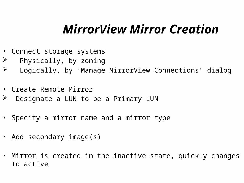
MirrorView Mirror Creation • Connect storage systems Physically, by zoning Logically, by ‘Manage MirrorView Connections’ dialog
• Create Remote Mirror Designate a LUN to be a Primary LUN
• Specify a mirror name and a mirror type
• Add secondary image(s)
• Mirror is created in the inactive state, quickly changes to active
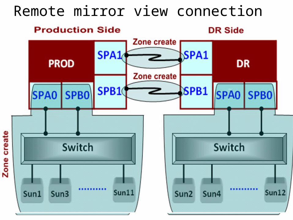
Remote mirror view connection
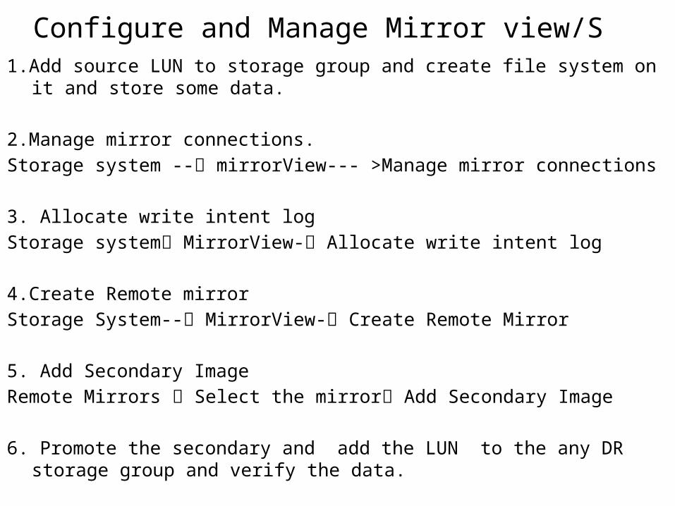
Configure and Manage Mirror view/S 1.Add source LUN to storage group and create file system on it and store some data.
2.Manage mirror connections.Storage system -- mirrorView--- >Manage mirror connections
3. Allocate write intent log Storage system MirrorView- Allocate write intent log
4.Create Remote mirrorStorage System-- MirrorView- Create Remote Mirror
5. Add Secondary ImageRemote Mirrors Select the mirror Add Secondary Image
6. Promote the secondary and add the LUN to the any DR storage group and verify the data.