Email Collector Quick Start Guide - juniper.net
69
Email Collector Quick Start Guide Published 2021-08-17
Transcript of Email Collector Quick Start Guide - juniper.net

Email Collector Quick Start Guide
Published
2021-08-17

Juniper Networks, Inc.1133 Innovation WaySunnyvale, California 94089USA408-745-2000www.juniper.net
Juniper Networks, the Juniper Networks logo, Juniper, and Junos are registered trademarks of Juniper Networks, Inc.in the United States and other countries. All other trademarks, service marks, registered marks, or registered servicemarks are the property of their respective owners.
Juniper Networks assumes no responsibility for any inaccuracies in this document. Juniper Networks reserves the rightto change, modify, transfer, or otherwise revise this publication without notice.
Email Collector Quick Start GuideCopyright © 2021 Juniper Networks, Inc. All rights reserved.
The information in this document is current as of the date on the title page.
YEAR 2000 NOTICE
Juniper Networks hardware and software products are Year 2000 compliant. Junos OS has no known time-relatedlimitations through the year 2038. However, the NTP application is known to have some difficulty in the year 2036.
END USER LICENSE AGREEMENT
The Juniper Networks product that is the subject of this technical documentation consists of (or is intended for usewith) Juniper Networks software. Use of such software is subject to the terms and conditions of the End User LicenseAgreement ("EULA") posted at https://support.juniper.net/support/eula/. By downloading, installing or using suchsoftware, you agree to the terms and conditions of that EULA.
ii

Table of Contents
About This Guide | v
1 Email Collector Quick Start Guide
Overview | 3
On-Premise Juniper ATP Appliance-MTA-Receiver Deployments | 4
Generalized Administrator Tasks for Juniper ATP Appliance On-Premise MTADeployments | 6
On-Premise BCC Email Collector Deployments | 6
Configuring Collector Email Journaling | 7
Email Journaling | 8
Create a Journaling Mailbox on the Exchange Server | 9
Configuring a Mailbox Database | 9
Configuring Microsoft Exchange Server 2013 Journaling | 10
Configuring Microsoft Exchange Server 2010 Journaling | 11
Create a journaling contact | 12
Create an SMTP send connector | 13
Activate journaling | 16
Implement journal rules (select users only) | 18
Configuring Exchange-Server Journal Polling from the Juniper ATP Appliance CM Web UI | 20
Configuring Office 365 Journaling | 21
Configuring Gmail Journaling | 23
Core/CM and All-in-One Email Collector Installation Options | 27
Installing the Juniper ATP Appliance Collector Open Virtual Appliance (OVA) | 29
OVA Deployment vSwitch Setup | 31
To install the JATP Appliance OVA to a VM | 31
Installing and Configuring the AWS vCore AMI | 33
iii

Part 1- Amazon AWS Management Console vCore AMI Configuration | 34
Part 2 - Running the Juniper ATP Appliance vCore AMI Instance | 39
Verifying AWS Configurations | 44
Configuring Juniper ATP Appliance Email Traffic Collection | 45
Setting the same Device Key Passphrase on all Juniper ATP Appliance Devices | 48
Verifying Configurations and Traffic from the CLI | 49
Accessing the Juniper ATP Appliance Central Manager Web UI | 50
To Log in to the Central Manager Web UI | 50
Changing the Appliance Type | 52
Appendix A: Deploy JATP Email Threat Mitigation for Office 365 (A Start to FinishExample) | 54
Overview | 55
Register a New Application in the Azure Portal | 56
Obtain the Application ID and Object ID | 56
Obtain the Directory ID | 57
Provide API Access Permissions | 57
Download the Manifest File | 58
Configure Email Mitigation Settings in JATP | 59
Upload the Manifest File | 60
Configure Office 365 Journaling for JATP Mitigation | 60
Configure the Email Collector on JATP | 62
Test the Configuration | 63
What to Do Next? | 63
iv

About This Guide
Use this guide to configure the JATP email collector to detect malicious URLs and attachments deliveredover email.
v

1CHAPTER
Email Collector Quick Start Guide
Overview | 3
On-Premise Juniper ATP Appliance-MTA-Receiver Deployments | 4
Generalized Administrator Tasks for Juniper ATP Appliance On-Premise MTADeployments | 6
On-Premise BCC Email Collector Deployments | 6
Configuring Collector Email Journaling | 7
Configuring Gmail Journaling | 23
Core/CM and All-in-One Email Collector Installation Options | 27
Installing the Juniper ATP Appliance Collector Open Virtual Appliance (OVA) | 29
Installing and Configuring the AWS vCore AMI | 33
Verifying AWS Configurations | 44
Configuring Juniper ATP Appliance Email Traffic Collection | 45
Setting the same Device Key Passphrase on all Juniper ATP Appliance Devices | 48
Verifying Configurations and Traffic from the CLI | 49
Accessing the Juniper ATP Appliance Central Manager Web UI | 50
Changing the Appliance Type | 52
Appendix A: Deploy JATP Email Threat Mitigation for Office 365 (A Start to FinishExample) | 54
What to Do Next? | 63


Overview
Welcome to the Juniper ATP Appliance Email Collector Quick Start Guide.
Juniper ATP Appliance’s Email Collector detects malicious URLs and attachments delivered via email andcorrelates these detections with web downloads and lateral spread events. There are three Juniper ATPAppliance email options:
• An On-Premise Email MTA-Receiver
• A BCC or Journal Email Server Account
Figure 1: Juniper ATP Appliance Email Collection and Detection Options
NOTE: A Juniper ATP Appliance Advanced license is required for advanced Email Detectionconfigurations.
RELATED DOCUMENTATION
On-Premise Juniper ATP Appliance-MTA-Receiver Deployments | 4
On-Premise BCC Email Collector Deployments | 6
Core/CM and All-in-One Email Collector Installation Options | 27
3
On-Premise Juniper ATP Appliance-MTA-ReceiverDeployments
Juniper ATP Appliance MTA Receiver deployments collect emails from different servers including Office365, Gmail and MS Exchange. It also supports any other email servers/anti-spam gateway that supportsadditional SMTP receivers for sending emails to the Juniper ATP
Appliance MTA Receiver (without adding any SMTP envelop headers to make the original email anattachment). The Juniper ATP Appliance admin must configure the supported servers (to direct the emailstream to the Juniper ATP Appliance MTA Receiver) using the email address setup on the MTA Receiver(for example: CustomerX@MTA-IP or CustomerX@DomainName.
Juniper ATP Appliance’s On-Premise MTA Receiver extracts objects/URL links and submits them to theJuniper ATP Appliance Core for analysis. With multi-vector threat detection, if existing securityinfrastructure fails to detect a phishing link, Juniper ATP Appliance monitors the download from thatlink, detects the CnC callbacks caused by the download, correlates any lateral spread that the downloadcan trigger, and blocks the threat with mitigation. Benefits include:
• Visibility into email borne threats at high scale (2.4 Million emails/day)
• Detection of Malicious Email Attachments and URL Links
4

• Ability to quarantine malicious emails
Figure 2: Juniper ATP Appliance Email MTA-Receiver Deployment Options: (a) for Office 365 andGmail Analysis
Figure 3: Juniper ATP Appliance Email MTA-Receiver Deployment Options:(b)
RELATED DOCUMENTATION
Generalized Administrator Tasks for Juniper ATP Appliance On-Premise MTA Deployments | 6
On-Premise BCC Email Collector Deployments | 6
5

Generalized Administrator Tasks for Juniper ATPAppliance On-Premise MTA Deployments
After installing a Juniper ATP Appliance Core or All-in-One system, both of which contain an EmailTraffic Collector in the Core component, an admin will need to perform the following tasks:
• open a firewall rule to allow emails from office 365/gmail to the mta (from *.protection.outlook.comto JunipeATPmta_external_ip:25)
• use the external ip address or fqdn of the mta to create a journal rule in office 365 ([email protected] [email protected])
• configure mailbox name and mta ip from the Juniper ATP Appliance web interface in:
• System Profiles > Email Collector > Add New Email Collector > Juniper ATP Appliance MTAReceiver
• Configure Mitigation information To Auto-Mitigate: Environmental Settings > Email MitigationSettings
• ports used:
• (Collection) Office 365 / Gmail / Exchange Connects To MTA using TCP:25 (Inbound) (TLS Can BeEnabled)
• (Submission) MTA Connects To Core/CM Using TCP:443
• (Mitigation) Core/cm Connects To Office 365/ Gmail Using TCP:443 (Outbound)
RELATED DOCUMENTATION
On-Premise BCC Email Collector Deployments | 6
On-Premise BCC Email Collector Deployments
This method of email collection relies on a BCC or Journal mailbox which receives copies of emails to beinspected. The Juniper ATP Appliance BCC email collector periodically pulls these emails to examinethem for threats.
6

Microsoft Exchange Server journaling can be configured to record a copy (a journal) of enterprise emailmessages, and then periodically send them to a journal mailbox on the Exchange Server.
NOTE: No email or email data is stored on the Traffic Collector. On the Juniper ATP ApplianceCore, extracted objects and some meta data (such as source and destination email addresses,timestamp data, etc., are stored and Juniper ATP Appliance logs email header info in the log file.No text from the email is retained (except for the attachment(s) for malware detonation andanalysis)
Exchange Server 2010 can be configured to support envelope journaling only. This means that a copy ismade of each email message body and its transport information. The transport information is essentiallyan envelope that includes the email sender and all recipients. The Juniper ATP Appliance Email Collectorpolls the Exchange Server for journal entries and as scheduled, pulls all the emails in the journal accountfrom the exchange server to the Collector. The Email Collector uses journaling for initial traffic analysisand email attachment monitoring/ inspection.
All urls and email attachments are sent from the Email Collector to the Juniper ATP Appliance Core fordetonation in the Juniper ATP Appliance SmartCore. When email-based malware or malicious emailattachments are detected, the journal entry is incorporated into the analysis results by the Juniper ATPAppliance Central Manager and sent out as a notification to the Juniper ATP Appliance administrator,with corresponding mitigation and/or infection verification actions detailed in the Central Manager WebUI.
NOTE: Juniper ATP Appliance supports journaling for Exchange 2010 and later.
To setup Email Collector Journaling, refer to the next section.
Configuring Collector Email Journaling
IN THIS SECTION
Email Journaling | 8
Create a Journaling Mailbox on the Exchange Server | 9
Configuring a Mailbox Database | 9
7
Configuring Microsoft Exchange Server 2013 Journaling | 10
Configuring Microsoft Exchange Server 2010 Journaling | 11
Configuring Exchange-Server Journal Polling from the Juniper ATP Appliance CM Web UI | 20
Configuring Office 365 Journaling | 21
After installing a Juniper ATP Appliance Core or All-in-One system, both of which contain an EmailTraffic Collector in the Core component, you will need to configure an exchange server journal accountfor the Collector to poll, and set Postfix to forward Gmail Bcc (blind carbon copies) of all mail traffic tothe Collector as a default forwarding mechanism.
Email Journaling
Juniper ATP Appliance Traffic Collectors continuously monitor and inspect all network traffic formalware objects; extracting and sending objects to the Core for distribution to the Windows or MacDetection Engines.
For Windows traffic, Microsoft Exchange Server journaling can be configured to record a copy (a journal)of enterprise email messages, and then periodically send them to a journal mailbox on the ExchangeServer.
NOTE: No email or email data is stored on the Traffic Collector. On the Juniper ATP ApplianceCore, extracted objects and some meta data (such as source and destination email addresses,timestamp data, etc., are stored and Juniper ATP Appliance logs email header info in the log file.No text from the email is retained (except for the attachment(s) for malware detonation andanalysis)
Exchange Server 2010 can be configured to support envelope journaling only. This means that a copy ismade of each email message body and its transport information. The transport information is essentiallyan envelope that includes the email sender and all recipients.
The Juniper ATP Appliance Email Collector polls the Exchange Server for journal entries and as-scheduled, pulls all the emails in the journal account from the exchange server to the Collector. TheEmail Collector uses journaling for initial traffic analysis and email attachment monitoring/inspection. Allemail traffic (and email attachments) are sent from the Email Collector to the Juniper ATP ApplianceCore for detonation in the Windows or Mac OS X detection engines.
8
When email-based malware or malicious email attachments are detected, the journal entry isincorporated into the analysis results by the Juniper ATP Appliance Central Manager and sent out as anotification to the Juniper ATP Appliance administrator, with corresponding mitigation and/or infectionverification actions detailed in the Central Manager Web UI.
NOTE: Juniper ATP Appliance supports journaling for Exchange 2010 and later.
To setup Email Collector Journaling, use the following procedures:
Create a Journaling Mailbox on the Exchange Server
NOTE: See also “Configuring Microsoft Exchange Server 2013 Journaling.”
1. Launch Microsoft Exchange Management Console.
2. Expand Recipient Configuration node and click on Mailbox node.
3. Select New Mailbox… from the Actions pane.
4. Select User Mailbox option and click Next.
5. Select New user option and click Next.
6. Enter New user mailbox details
7. Enter the ‘User information’ details for the Collector to which the new journaling mailbox will beassigned and click Next.
8. Enter an ‘Alias’ for the journaling mailbox and click Next.
9. Click Next again and review the new mailbox summary for the new mailbox to create, then clickNew.
10. Now that the journaling mailbox is created, configure standard journaling by configuring a MailboxDatabase.
Configuring a Mailbox Database
• In the Microsoft Exchange Management Console>Server Configuration, click on Mailbox database.
• In the Toolbox Actions of Selected Mailbox Database, click on Properties.
9

• In the Mailbox Database Properties page, go to the General tab and select the Journal Recipientcheckbox, BUT, before selecting the checkbox, first click on Browse and choose which mailbox willget all messages from the mailbox database. After checking Journal Recipient, click OK to finish.
Configuring Microsoft Exchange Server 2013 Journaling
[See also Configuring Microsoft Exchange Server 2010 Journaling in the next section.]
1. Login to the MS Exchange Server Admin Center at: https://exchnageserverip/ecp/
2. Select the Send Connectors tab.
3. Navigate to mail flow>>send connectors and enter Send Connector settings:
Figure 4: Send Connector Settings
4. Save the connector settings.
5. Navigate to Compliance Management>>Journal Rules to configure Journal rules.
6. Provide the mailboxname and ip address in the “Send Journal Reports To” field .
10

NOTE: This should match the mailbox name configured at the Juniper ATP Appliance EmailCollector Config>System Profiles>Email Collector Web UI page.
Figure 5: Setting Journal Rules
Configuring Microsoft Exchange Server 2010 Journaling
IN THIS SECTION
Create a journaling contact | 12
Create an SMTP send connector | 13
Activate journaling | 16
Implement journal rules (select users only) | 18
To configure Journaling on your Exchange 2010 server, follow these steps:
• Set up a journaling contact
• Configure an SMTP send connector
• Activate journaling
11

• Implement journal rules (select users only)
[See also Configuring Microsoft Exchange Server 2013 Journaling in the previous section.]
Create a journaling contact
1. Select Start > All Programs > Microsoft Exchange Server 2010 > Exchange Management Console.
2. Click the + sign to the left of your Exchange server.
3. Click the + sign to the left of Recipient Configuration.
4. Click Mail Contact under Recipient Configuration.
5. In the Mail Contact page (a), click New Mail Contact in the Actions pane (b).
6. Select the New Contact option (a) and then click Next (b).
7. In the New Mail Contact window, type Journaling in the First Name field, Contact in the Last Namefield and Journaling Contact in the Alias field (a). Click Edit (b).
8. Type the journaling address (a) and click OK (b).
12

NOTE: The journaling address is unique to your organization. If you were provided with thisaddress, please contact customer support.
9. Click Next.
10. Click New.
11. Click Finish.
Create an SMTP send connector
1. Select Start > All Programs > Microsoft Exchange Server 2010 > Exchange Management Console.
2. Click the + sign to the left of your Exchange server.
3. Click the + sign to the left of Organization Configuration.
4. Click Hub Transport.
5. Click the Send Connectors tab.
6. In the Actions pane, click New Send Connector.
7. Type Journaling Connector for the Name field, for the Select the intended use for this Sendconnector dropdown list, select Custom (a). Click Next (b).
13

8. Click Add. The SMTP Address Space window opens.
9. In the Address field, type the Address Space (a). Leave the cost at 1 and then click OK (b).
10. Click Next.
11. Select the Route mail through the following smart hosts option and then click Add.
12. Select the Fully qualified domain name (FQDN) option, type the smart host provided to you andthen click OK.
14

13. Click Next.
14. Select None for the Configure smart host authentication settings and then click Next.
NOTE: Exchange 2010 servers automatically send all outbound email via TLS encryption: nooutbound security configuration is required by the Administrator.
15. Click Next.
16. Click New.
17. Click Finish. The configured send connector is shown below.
15

Activate journaling
1. Select Start > All Programs > Microsoft Exchange Server 2010 > Exchange Management Console.
2. Click the + sign to the left of your Exchange server.
3. Click the + sign to the left of Organization Configuration.
4. Click Mailbox.
5. In the Database Management tab, right click your mailbox database and select Properties.
16

6. Click the Maintenance tab.
7. Select the Journal Recipient check box (a), and then click Browse (b).
17

8. Select Journaling Contact (a) and then click OK (b).
9. Click OK. Message journaling is now activated.
Implement journal rules (select users only)
1. Select Start > All Programs > Microsoft Exchange Server 2010 > Exchange Management Console.
2. Click the + sign to the left of your Exchange server.
3. Click the + sign to the left of Organization Configuration.
4. Click Hub Transport.
5. Click the Journal Rules tab.
6. In the Actions pane, click New Journal Rule. The New Journal Rule window appears.
7. In the Rule Name field, type Journaling Rule (a) and then click Browse (b).
18

8. Select Journaling Contact from the list and then click OK.
9. Select the Journal messages for recipient check box and then click Browse.
10. Select Journaling Distro from the list (a) and click OK (b).
19

• Click OK to complete configuration of journal rules for select users in your organization.
Configuring Exchange-Server Journal Polling from the Juniper ATPAppliance CM Web UI
1. From the Juniper ATP Appliance Central Manager Config> System Profiles> Email Collector, click theAdd New Email Collector button, or click Edit for an existing Collector listed in the Current EmailCollectors table.
2. Enter and select the email journaling settings in the displayed configuration fields: Email Server [IP],Protocol, SSL, Mailbox Name, Password, Poll Interval (in minutes), Keep Mail on Server, and Enabled.
20
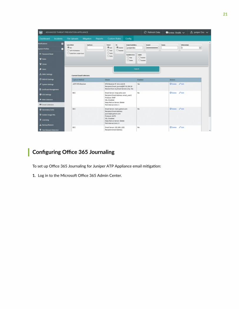
Configuring Office 365 Journaling
To set up Office 365 Journaling for Juniper ATP Appliance email mitigation:
1. Log in to the Microsoft Office 365 Admin Center.
21

2. From the Office 365 Admin Center, select Admin Centers > Exchange.
Figure 6: Microsoft Office 365 Admin Center
3. Select Compliance Management > Journal Rules.
4. Click on the + sign to add a new Journal Rule.
22

5. Complete the new journal rule form fields.
Figure 7: Setting a New Journal Rule
RELATED DOCUMENTATION
Configuring Gmail Journaling | 23
Configuring Gmail Journaling
Use the following procedure to configure email journaling for Gmail:
1. Navigate to the Google Admin Home site at https://admin.google.com/AdminHome.
2. From the Google Admin Console Dashboard, navigate to Apps->G Suite->Gmail->Advanced Settings.
23

NOTE: To view Advanced Settings, scroll to the bottom of the Gmail page.
3. Navigate to the Compliance Section and click Add Another Compliance Rule to setup deliver to theJuniper ATP Appliance MTA.
Figure 8: Google Gmail Admin Home Journaling Settings
24
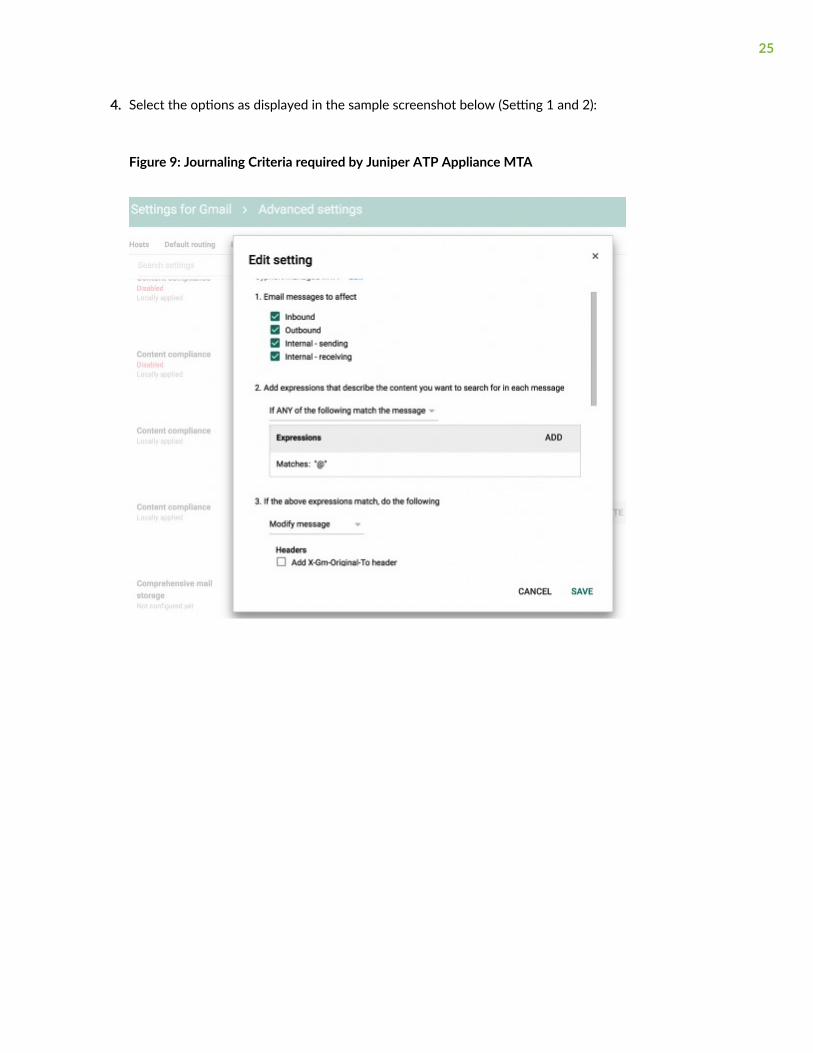
4. Select the options as displayed in the sample screenshot below (Setting 1 and 2):
Figure 9: Journaling Criteria required by Juniper ATP Appliance MTA
25

5. Be sure to add the Recipient information (this is the Juniper ATP Appliance MT); for example:JATP_mta@FQDN or JATP_mta@ip.
Figure 10: Setting the Juniper ATP Appliance MTA as the Gmail Recipient: JATP_mta@FQDN
• Refer to the Juniper ATP Appliance Operator’s Guide for information about configuring emaildetection mitigations.
RELATED DOCUMENTATION
Configuring Collector Email Journaling | 7
26
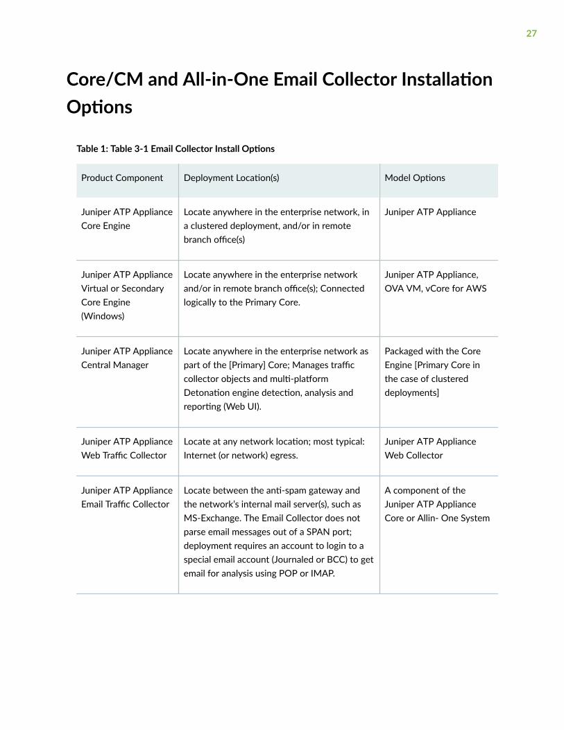
Core/CM and All-in-One Email Collector InstallationOptions
Table 1: Table 3-1 Email Collector Install Options
Product Component Deployment Location(s) Model Options
Juniper ATP ApplianceCore Engine
Locate anywhere in the enterprise network, ina clustered deployment, and/or in remotebranch office(s)
Juniper ATP Appliance
Juniper ATP ApplianceVirtual or SecondaryCore Engine(Windows)
Locate anywhere in the enterprise networkand/or in remote branch office(s); Connectedlogically to the Primary Core.
Juniper ATP Appliance,OVA VM, vCore for AWS
Juniper ATP ApplianceCentral Manager
Locate anywhere in the enterprise network aspart of the [Primary] Core; Manages trafficcollector objects and multi-platformDetonation engine detection, analysis andreporting (Web UI).
Packaged with the CoreEngine [Primary Core inthe case of clustereddeployments]
Juniper ATP ApplianceWeb Traffic Collector
Locate at any network location; most typical:Internet (or network) egress.
Juniper ATP ApplianceWeb Collector
Juniper ATP ApplianceEmail Traffic Collector
Locate between the anti-spam gateway andthe network’s internal mail server(s), such asMS-Exchange. The Email Collector does notparse email messages out of a SPAN port;deployment requires an account to login to aspecial email account (Journaled or BCC) to getemail for analysis using POP or IMAP.
A component of theJuniper ATP ApplianceCore or Allin- One System
27

Table 1: Table 3-1 Email Collector Install Options (Continued)
Product Component Deployment Location(s) Model Options
Juniper ATP ApplianceMac OS X
Locate anywhere in the enterprise networkand/or in remote branch office(s); Connectedlogically to the Primary Core.
Juniper ATP Appliance onMac Mini Device
Juniper ATP ApplianceAll-In- One
Locate anywhere in the enterprise network. Juniper ATP Appliance
Global SecurityServices (GSS)
Configured for any of the Juniper ATPAppliance CM/ Core appliances or All-in-Oneappliances.
Service
clustered or virtual Software and Cloud-based deployment: VirtualCollector, Virtual Core for AWS, and vCore(OVA)
Many options; refer torespective Juniper ATPAppliance Quick StartGuide
NOTE: For hardware installation instructions, refer to the Juniper Networks Advanced ThreatPrevention Appliance Hardware Guide.
RELATED DOCUMENTATION
Installing the Juniper ATP Appliance Collector Open Virtual Appliance (OVA) | 29
Installing and Configuring the AWS vCore AMI | 33
Changing the Appliance Type | 52
28
Installing the Juniper ATP Appliance Collector OpenVirtual Appliance (OVA)
IN THIS SECTION
OVA Deployment vSwitch Setup | 31
To install the JATP Appliance OVA to a VM | 31
Juniper ATP Appliance’s extensible deployment options include a Virtual Collector (vCollector) product,as an Open Virtual Appliance, or OVA, that runs in virtual machines. Specifically, a Juniper ATPAppliance OVA-packaged image is available for VMware Hypervisor for vSphere 6.5, 6.0, 5.5 and 5.0.Virtual Collector models supporting 25 Mbps, 100 Mbps, 500 Mbps and a 1.0 Gbps are available.
An OVF package consists of several files contained in a single directory with an OVF descriptor file thatdescribes the Juniper ATP Appliance virtual machine template and package: metadata for the OVFpackage, and a Juniper ATP Appliance software image. The directory is distributed as an OVA package (atar archive file with the OVF directory inside).
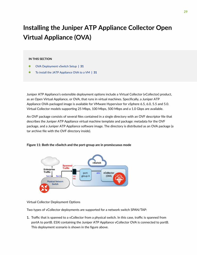
Figure 11: Both the vSwitch and the port-group are in promiscuous mode
Virtual Collector Deployment Options
Two types of vCollector deployments are supported for a network switch SPAN/TAP:
1. Traffic that is spanned to a vCollector from a physical switch. In this case, traffic is spanned fromportA to portB. ESXi containing the Juniper ATP Appliance vCollector OVA is connected to portB.This deployment scenario is shown in the figure above.
29

2. Traffic from a virtual machine that is on the same vSwitch as the vCollector. In this deploymentscenario, because the vSwitch containing the vCollector is in promiscuous mode, by default all port-groups created will also be in promiscuous mode. Therefore, 2 port groups are recommendedwherein port-groupA (vCollector) in promiscuous mode is associated with the vCollector, and port-groupB (vTraffic) represents traffic that is not in promiscuous mode.
NOTE: Traffic from a virtual machine that is not on the same vSwitch as the vCollector is notsupported. Also, a dedicated NIC adapter is required for the vCollector deployment; attachthe NIC to a virtual switch in promiscuous mode (to collect all traffic). If a vSwitch is inpromiscuous mode, by default all port-groups are put in promiscuous mode and that meansother regular VMs are also receiving unnecessary traffic. A workaround for that is to create adifferent port-group for the other VMs and configure without promiscuous mode.
Table 2: Provisioning Requirements
VM vCenter VersionSupport
Recommended vCollectorESXi Hardware
vCollector CPUs vCollectorMemory
VM vCenter ServerVersion: 6.5, 6.0, 5.5and 5.0
vSphere ClientVersion: 6.5, 6.0, 5.5and 5.0
ESXi version: 5.5.0and 5.5.1
Processor speed 2.3-3.3GHz
As many physical CORES asvirtual CPUs
Hyperthreading: eitherenable or disable
Reservation: Default
CPU Limit: Unlimited
Hyperthreaded CoreSharing Mode: None (ifHyperthreading is enabledon the ESXi)
MemoryReservation:Default
Memory Limit:Unlimited
Table 3: Sizing Options
Model Performance Number of vCPUs Memory Disk Storage Emails/Day
vC--v500M 500 Mbps 8 16 GB 512 GB 720 thousand
vC--v1G 1 Gbps 16 16 GB 512 GB 1.4 million
vC-v2.5G 2.5 Gbps 24 32 GB 512 GB 2.4 million
30

NOTE: VDS and DVS are not supported in this release.
OVA Deployment vSwitch Setup
1. Identify the physical network adapter from which the spanned traffic is received, then create a newVMware Virtual Switch and associate it with the physical network adapter.
2. Click on Virtual Switch Properties. On the Ports tab, select vSwitch and click on the Edit button.
3. Select the Security tab and change Promiscuous Mode to accept, then click OK. Click OK again toexit.
4. Create a new port-group “vtraffic” in the Virtual Switch. This new port-group will be assigned to yourvCollector later. See vSwitch Tip below for information about troubleshooting this setup.
To install the JATP Appliance OVA to a VM
1. Download the JATP OVA file to a desktop system that can access VMware vCenter.
2. Connect to vCenter and click on File>Deploy OVF Template.
3. Browse the Downloads directory and select the OVA file, then click Next to view the OVF TemplateDetails page.
4. Click Next to display and review the End User License Agreement page
5. Accept the EULA and click Next to view the Name and Location page
6. a default name is created for the Virtual Email Collector. If desired, enter a new name.
7. Choose the Data Center on which the vCollector will be deployed, then click Next to view theHost/Cluster page.
8. Choose the host/cluster on which the vCollector will reside, then click Next to view the Storagepage.
9. Choose the destination file storage for the vCollector virtual machine files, then click Next to viewthe Disk Format page. The default is THIN PROVISION LAZY ZEROED which requires 512GB offree space on the storage device. Using Thin disk provisioning to initially save on disk space is alsosupported.
Click Next to view the Network Mapping page.
10. Set up the Virtual Email Collector management interface: This interface is used to communicatewith the JATP Central Manager (CM). Assign the destination network to the port-group that hasconnectivity to the CM Management Network IP Address.
31

11. IP Allocation Policy can be configured for DHCP or Static addressing-- Juniper recommends usingSTATIC addressing. For DHCP instructions, skip to Step 12. For IP Allocation Policy as Static,perform the following assignments:
• IP Address: Assign the Management Network IP Address for the Virtual Collector; it should be inthe same subnet as the management IP address for the JATP Central Manager.
• Netmask: Assign the netmask for the Virtual Collector.
• Gateway: Assign the gateway for the Virtual Collector.
• DNS Address 1: Assign the primary DNS address for the Virtual Collector.
• DNS Address 2: Assign the secondary DNS address for the Virtual Collector.
12. Enter the Search Domain and Hostname for the Virtual Collector.
13. Complete the JATP vCollector Settings:
• New JATP CLI Admin Password: this is the password for accessing the Virtual Collector from theCLI.
• JATP Central Manager IP Address: Enter the management network IP Address configured forthe Central Manager. This IP Address should be reachable by the Virtual Collector ManagementIP Address.
• JATP Device Name: Enter a unique device name for the Virtual Collector.
• JATP Device Description: Enter a description for the Virtual Collector.
• JATP Device Key Passphrase: Enter the passphrase for the Virtual Collector; it should beidentical to the passphrase configured in the Central Manager for the Core/CM. Click Next toview the Ready to Complete page.
14. Do not check the Power-On After Deployment option because you must first (next) modify theCPU and Memory requirements (depending on the sizing options available). It is important toreserve CPU and memory for any virtual deployment.
15. To configure CPU and memory reservation:
• For CPU reservation: Right click on vCollector-> Edit settings:
• Select Resources tab, then select CPU.
• Under Reservation, specify the guaranteed CPU allocation for the VM. It can be calculatedbased on Number of vCPUs processor speed.
• For Memory Reservation: Right click on vCollector -> Edit settings.
• In the Resources tab, select Memory.
32

• Under Reservation, specify the amount of Memory to reserve for the VM. It should be the sameas the memory specified by the Sizing guide.
16. If Hyperthreading is enabled, perform the followings elections:
• Right click on the virtual collector -> Edit settings.
• In the Resources tab, select HT Sharing: None for Advanced CPU.
17. Power on the Virtual Email Collector.
RELATED DOCUMENTATION
Installing and Configuring the AWS vCore AMI | 33
Installing and Configuring the AWS vCore AMI
IN THIS SECTION
Part 1- Amazon AWS Management Console vCore AMI Configuration | 34
Part 2 - Running the Juniper ATP Appliance vCore AMI Instance | 39
Juniper ATP Appliance vCore for AWS requires both Juniper ATP Appliance and AWS licensed accounts.The installations and configuration process uses both the Amazon AWS Management Console (Part 1) aswell as the Juniper ATP Appliance vCore Central Manager Web UI and CLI (Part 2).
NOTE: After purchasing the vCore AMI license, share the vCore AMI with your AWS customeraccount by using the AWS Management Console to configure and launch the vCore AMI. Referto the Juniper ATP Appliance vCore for AWS Quick Start Guide for more information.
A general AWS AMI configuration workflow is provided below; be sure to refer to the AWSManagement Console operations guide for more detailed console usage information.
33

Part 1- Amazon AWS Management Console vCore AMI Configuration
1. Log into your AWS database account at the Amazon AWS Management Console.
console.aws.amazon.com
2. From the AWS Management Console Dashboard, select EC2 services.
3. In EC2 Services, click the IMAGES>AMIs option from the left menu of the AWS Console. Also clickon the drop-down menu to change the image ownership type from "Owned by Me" to "PrivateImages".:
34

4. Select the Juniper ATP Appliance AMI image to be installed by clicking its radio button in the table.
5. From the Zone DropDown menu, select the Zone for which the AMI is to be configured. In ourexample, the Juniper ATP Appliance “rsa-demo-cm” AMI is selected. (The Juniper ATP ApplianceAMI will have been shared with you before you launch the AWS Core.)
6. Click Launch to begin configuration of this Juniper ATP Appliance vCore AMI instance, in EC2, foryour enterprise.
7. From the “Choose an Instance Type” page, select an instance type for the AMI. In our example, weselected “c4 large”. Click Next: Configure Instance.
8. From the “Configure Instance Details” page, select an existing customer-defined Virtual PrivateCloud (VPC) from the Network dropdown menu; in our example, we’ve selected rsa-demo-1.
To create a new VPC, click the Create New VPC link and follow the stepped procedure.
9. Define the VPC subnet in the Subnet field; in our example, we used AWS 10.2.0.0/16.
35

To create a new subnet, click the Create New Subnet link and follow the stepped procedure.
10. Confirm that the subnet us using an Auto-Assigned Public IP, as in the example shown above. Thisallows the Juniper ATP Appliance vCore to be accessed from the Internet.
11. Click to Enable termination protection to protect against accidental termination.
NOTE: Each AMI instance uses a private IP and a public IP. If you are planning on installingone vCore + Central Manager with several Secondary Core, you must have a public IPaddress assignment. Note that the Secondary Core does not need a public IP because itdoers not contain a Web UI.
ALSO: Some enterprises connect their AWS VPC to a private network using VPN. In thiscase, there is no need to assign a public IP to the subnet because internet access can beconfigured via the VPN.
12. Click Next: Add Storage.
NOTE: Click "Encrypted" to encrypt the data volume.
13. Juniper ATP Appliance already provides 1 TeraByte of storage in the Core. Due to the limitations ofthe AWS storage volume max size, there is no need for further configuration on this page; do notadd extra storage to the vCore. Click Next.
36

14. From the “Tag Instance” page, click Create Tag and enter a tag name and description. Click Next:Configure Security to proceed.
15. A security group is essentially a firewall in AWS. Most customers already have a preexisting firewall,so choose Select an existing security group, or Create a new security group. Do ensure there arerules in the Security Group that allow communication between AWS Core and AWS SecondaryCores.
16. If creating a new security group, enter a name and description in the Security Group Name field andthe Description field, respectively.
17. Enter port designation; Juniper ATP Appliance vCore only allows for port 22, 80 and 443. ClickNext.
37

NOTE: You can configure an SSH key although the Juniper ATP Appliance vCore alreadyincludes password protection. To add extra protection, add a key pair first, then use JuniperATP Appliance password for CLI-only login. AWS requires you to set a key pair. You will notbe able to use a pem-only login.
18. To configure an SSH Key, select an existing key pair or create a new key pair:
19. If selecting an existing security group, select then choose from the list and click Next.
The “Review Instance Launch” page displays:
38

20. From the “Review Instance Launch” page, review the Instance Launch details, then either click EditInstance to make changes, or click Launch to instantiate.
The Launch Status window displays;
Part 2 - Running the Juniper ATP Appliance vCore AMI Instance
Next, you will initialize the Juniper ATP Appliance vCore AMI Instance from the AWS ManagementConsole, then verify the AMI at the Juniper ATP Appliance Central Manager CLI using the show ipcommand.
39
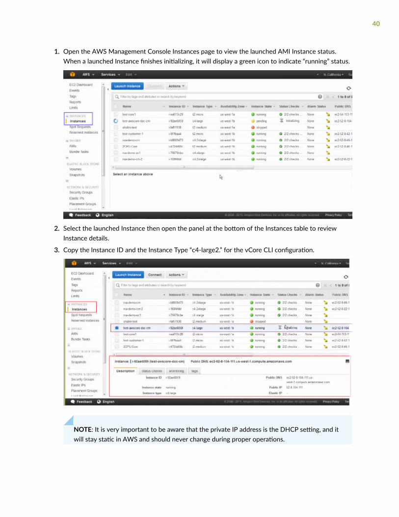
1. Open the AWS Management Console Instances page to view the launched AMI Instance status.When a launched Instance finishes initializing, it will display a green icon to indicate “running” status.
2. Select the launched Instance then open the panel at the bottom of the Instances table to reviewInstance details.
3. Copy the Instance ID and the Instance Type “c4-large2.” for the vCore CLI configuration.
NOTE: It is very important to be aware that the private IP address is the DHCP setting, and itwill stay static in AWS and should never change during proper operations.
40

Note also that you cannot change the AMI hostname, although you can change the DNS ifnecessary.
About DNS: Because the AWS vCore is not located in the enterprise, the reverse DNS onthreat targets do not resolve to the expected target hostname. This is rarely confusing whenconnected via VPN from the corporate network to the VPC. Generally, internal DNS serversare not exposed outside the enterprise, so Juniper ATP Appliance cannot configure the AWSvCore to reach an internal DNS server. If the internal DNS server uses an outward facing IPaddress and you, as admin, are willing to allow connections to it, this is a reasonable solution.Note that the DNS server that the vCore uses will not have the DNS information of thenetworks where the Juniper ATP Appliance Traffic Collector is located. This is typical ofdistributed deployments where the Traffic Collector and the Core/CM are not located in thesame enterprise networks.
4. Copy the Public IP address to access the vCore AWS Instance CLI via SSH/Putty:
5. At the Juniper ATP Appliance CLI prompt, type server to enter CLI Server mode, then from Servermode, run the CLI command show ip to display private and public IPs, as shown below. These shouldmatch the AWS configuration.
NOTE: For more information about AWS-specific CLI commands, and usage of CLI modes andcommands, refer to the Juniper ATP Appliance CLI Command Reference.
41

NOTE: Hybrid Cloud/Private Network deployments are not yet supported. All Juniper ATPAppliance Core components must be co-located on the AWS at this time. This means youcannot install the vCore on AWS and a Secondary Core on a private enterprise network(unless the private enterprise network is connected the to VPC where the AWS Core islocated using VPN).
6. After launching the AWS Core, the AMI vCore instance will boot up just like a regular appliance, andafter the vCore comes up, the next step is to run CLI setup wizard at the vCore CLI just like a regularvirtual Core. Refer to the Juniper ATP Appliance Core/Central Manager Quick Start Guide forinstructions on running the wizard to configure a Virtual Core. Also in the Quick Start Guide isinformation about installing additional Cores, Clustered Cores, Secondary Cores or OVA Cores.
NOTE: On the first boot of a virtual core (either AMI or OVA) with two disks configured, theappliance takes time to set up the second disk to be used. During this process, the system isnot ready for use; the full process may take up to 10 minutes. Wait 10 minutes after first bootbefore logging into the system to begin configuring it.
7. To create Secondary Cores for this AWS vCore, return to the AWS Management Console and launcha few more AMI Instances, then login to their CLIs via SSH and point those vCore Central Manager IPAddresses to the primary vCore CM. This process is described in the Juniper ATP Appliance Core/Central Manager Quick Start Guide in the section on Clustered Deployments.
42

8. For information about installing and configuring Juniper ATP Appliance Traffic Collectors for AWSvCore deployments, refer to Juniper ATP Appliance Traffic Collectors Quick Start Guide.
NOTE: Verify that there are no firewall rules blocking the outbound connections to the AWSCore. Be aware, however, that Outbound CnC detection traffic is blocked from leaving theAWS detection VMs.
9. View the AWS configuration from the Juniper ATP Appliance Central Manager Web UI; refer to thesection in this guide"Accessing the Juniper ATP Appliance Central Manager Web UI" on page 50 forinformation about accessing and navigating the CM Web UI.
On the Central Manager Config>Golden Image VMs page, note that 32-bit images are available forAWS; see figure below for reference.
RELATED DOCUMENTATION
Verifying AWS Configurations | 44
Accessing the Juniper ATP Appliance Central Manager Web UI | 50
43

Verifying AWS Configurations
To verify interface configurations, use the following CLI commands (refer to the Juniper ATP ApplianceCLI Command Reference for more information):
Table 4: CLI Commands
vCore CLI (Mode) & Command Purpose
JATP (diagnosis)# setupcheck allRun a check of all system components
JATP (server)# show interfaceVerify interface connectivity and status
JATP (server)# show ip <interface>Verify traffic [example: show ip eth1]
JATP (server)# ping x.x.x.xPing connected devices.
JATP (server)# show ipDisplay AWS public and private IP addresses.
JATP (server)# shutdownShutdown before moving a devices to a different location, or toperform server room maintenance etc
NOTE: Be sure to refer to the Juniper ATP Appliance CLI Command Reference for more information.
44

Configuring Juniper ATP Appliance Email TrafficCollection
When powered up, the Juniper ATP Appliance Collector performs its boot process and then displays aCLI login prompt. Use the following procedure to configure the Juniper ATP Appliance Server using theCLI command line and Configuration Wizard.
NOTE: FOR OVA DEPLOYMENTS: this configuration process is optional and can be skippedbecause these settings are addressed during OVA deployment to the VM vSwitch.
TIP: Integration requirements for the Email Collector: Microsoft Exchange 2010+
To Configure the Collector Configuration Wizard
1. At the login prompt, enter the default username admin and the password 1JATP234. Review thedisplayed EULA and press q to continue.
2. When prompted to accept the Juniper ATP Appliance End User License Agreement (EULA), enteryes. Configuration cannot continue until the EULA is accepted.
3. At the prompt, enter a new CLI administrator password. Weak passwords are not accepted. Note thatthe CLI admin password is maintained separately from the Juniper ATP Appliance Central ManagerWeb UI interface.
4. When prompted with the query “Do you want to configure the system using the ConfigurationWizard (Yes/ No)?”, enter yes.
5. Next, respond to the Configuration Wizard questions as follows in the Configuration Wizard sectionbelow.
Configuration Wizard Prompts Customer Responses/Actions
Use DHCP to obtain the IP address and DNSserver address for the management interface(Yes/No)?
We strongly discourage the use of DHCPaddressing because it changes dynamically. Astatic IP address is preferred.
Recommended: Respond with no:
45

NOTE: Note: Only if your DHCP response isno,enter the following information whenprompted:
• IP address
• Netmask
• Enter a gateway IP address for thismanagement (administrative) interface:
• Enter primary DNS server IP address.
• Do you have a secondary DNS Server (Yes/No).
• Do you want to enter the search domains?
• Enter the search domain (separate multiplesearch domains by space):
Enter a gateway IP X.X.X.X and quad-tuplenetmask using the form 255.255.255.0 (no CIDRformat).
• Enter an IP address
• Enter a netmask
• Enter a gateway IP address.
• Enter the DNS Server IP address
• If yes, enter the IP address of the secondaryDNS server.
• Enter yes if you want DNS lookups to use aspecific domain.
• Enter search domain(s) separated by spaces;for example: example.com lan.com dom2.com
Restart the eth0 interface (Yes/No)? Enter yes to restart with the new configurationsettings applied.
Enter a valid hostname. Type a unique hostname when prompted; do notinclude the domain; for example: JuniperATP1
46

[OPTIONAL]
If the system detects a Secondary Core with aneth2 port, then the alternate CnC exhaustoption is displayed:
Use alternate-exhaust for the analysis engineexhaust traffic (Yes/No)?
Enter IP address for the alternate-exhaust(eth2) interface:
Enter netmask for the alternate-exhaust (eth2)interface: (example: 255.255.0.0)
Enter gateway IP Address for the alternate-exhaust (eth2) interface: (example:10.6.0.1)
Enter primary DNS server IP Address for thealternateexhaust (eth2) interface: (example:8.8.8.8)
Do you have a secondary DNS server for thealternateexhaust (eth2) interface?
Do you want to enter the search domains forthe alternate-exhaust (eth2) interface?
NOTE: A complete network interface restartcan take more than 60 seconds
Enter yes to configure an alternate eth2interface.
Enter the IP address for the eth2 interface.
Enter the eth2 netmask.
Enter the gateway IP address.
Enter the primary DNS server IP Address for thealternate-exhaust (eth2) interface.
Enter yes or no to confirm or deny an eth2secondary DNS server.
Enter yes or no to indicate whether you want toenter search domain.
Enter the following server attributes:
Central Manager (CM) IP Address:
Device Name: (must be unique)
Device Description
Device Key PassPhrase
NOTE: Remember this passphrase and use forall distributed devices!
Enter the CM external IP address, not theloopback. in order to register with and view theCollector in the CM Web UI.
Enter the JuniperATP Collector device name;this identifies the Collector in the Web UI.
Enter a device Description
Enter the same PassPhrase used to authenticatethe Core to the Central Manager.
47

NOTE: Enter CTRL-C to exit the Configuration Wizard at any time. If you exit withoutcompleting the configuration, you will be prompted again whether to run the Wizard. Youmay also rerun the Wizard at any time with the CLI command wizard. Please refer to the CLIGuide for more information.
The Traffic Collector will now automatically “call home” to the Central Manager to announce it is onlineand active. Wait ~5 minutes and confirm Collector connectivity from the JuniperATP Web UI, asdescribed further below.
When the Configuration Wizard exits to display the CLI, you may use the commands listed in "VerifyingConfigurations and Traffic from the CLI" on page 49 to view interface configurations and to allowlist anEmail Collector (in distributed systems) if one is already installed and configured. Special characters usedin CLI parameters must be enclosed in double quotation marks.
To exit the CLI, type exit. Be sure to confirm Collector activity from the JuniperATP Central ManagerWeb UI (below).
JATP (collector)# exit
RELATED DOCUMENTATION
Verifying Configurations and Traffic from the CLI | 49
Setting the same Device Key Passphrase on allJuniper ATP Appliance Devices
The same device key must be set on all Juniper ATP Appliance devices in your network, no matter howremote the distributed devices may be. To set a device key passphrase, SSH into the device, login, anduse the following CLI commands:
JATP (server)# set passphrase <strongPassphraseHash>JATP (server)# show device key
48
NOTE: Always use the latest version of Putty for SSH operations, if using Putty as an SSH client.
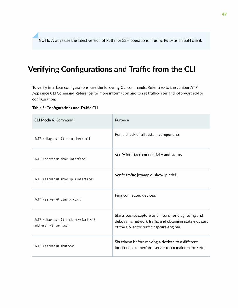
Verifying Configurations and Traffic from the CLI
To verify interface configurations, use the following CLI commands. Refer also to the Juniper ATPAppliance CLI Command Reference for more information and to set traffic-filter and x-forwarded-forconfigurations:
Table 5: Configurations and Traffic CLI
CLI Mode & Command Purpose
JATP (diagnosis)# setupcheck allRun a check of all system components
JATP (server)# show interfaceVerify interface connectivity and status
JATP (server)# show ip <interface>Verify traffic [example: show ip eth1]
JATP (server)# ping x.x.x.xPing connected devices.
JATP (diagnosis)# capture-start <IP address> <interface>
Starts packet capture as a means for diagnosing anddebugging network traffic and obtaining stats (not partof the Collector traffic capture engine).
JATP (server)# shutdownShutdown before moving a devices to a differentlocation, or to perform server room maintenance etc
49
Table 5: Configurations and Traffic CLI (Continued)
CLI Mode & Command Purpose
NOTE: Be sure to refer to the Juniper ATP Appliance CLI Command Reference for more information.Special characters used in CLI parameters must be enclosed in double quotation marks.
Accessing the Juniper ATP Appliance CentralManager Web UI
IN THIS SECTION
To Log in to the Central Manager Web UI | 50
To access the Juniper ATP Appliance Central Manager (CM) Web UI, use HTTP/HTTPS and enter theconfigured Juniper ATP Appliance CM IP address or hostname in a web browser address field, thenaccept the SSL certificate when prompted. Login is required
To Log in to the Central Manager Web UI
1. In the Juniper ATP Appliance Login window, enter the default username admin and the passwordjuniper.
NOTE: The Juniper ATP Appliance Web UI login username and password are separate fromthe CLI admin username and password.
2. When prompted to reset the password, re-enter the password juniper
as the “old” password, and enter a new password (twice).
50

3. At login, the Juniper ATP Appliance Central Manager Dashboard is displayed, as shown below. TheDashboard tab includes aggregated malware detection information and provides system status andhealth information
4. Configuration informations for Email Collectors and MTAs are made from the Configuration tab.Refer to the Juniper ATP Appliance Operator’s Guide for more information.
Web UI Navigation Tabs
• Dashboards: Review malware summaries, lateral progressions and trends
• Incidents: View detected incidents and their behaviors
• File Uploads: Submit files for malware analysis
• Mitigation: Perform immediate threat verification & mitigation actions
• Reports: Configure & view malware activity and audits
• Custom Rules: Create and Manage custom security rules
• Configuration: Config and modify Juniper ATP Appliance Settings
Figure 12: Central Manager Dashboards
• The Juniper ATP Appliance CM Dashboard views (Operations | Research | System | Collectors [Web |Email]) provide in-context and aggregated malware detection information as well as system statusand health statistics.
51

The Juniper ATP Appliance CM Dashboard provides in-context and aggregated malware detectioninformation for web and email traffic as well as system status and health information. Additionalconfigurations are made from the Configuration tab. Refer to the Juniper ATP Appliance Operator’sGuide or online help for more information. Use the Config tab to verify that the new Collector is callingthe Central Manager (CM) Web UI, and is online and actively inspecting and collecting traffic.
Changing the Appliance Type
In release version 5.0.4, a single ISO is provided for all appliance types (All-In-One, Email Collector,Traffic Collector, Core/Central Manager). If you don’t change the form factor during the installation, allappliances initially boot-up as an All-In-One appliance. You can keep this type or change the type byselecting a different type in the wizard screen that appears following the EULA, after boot-up. See thehardware installation guide for details.
In addition to changing the appliance type after the initial installation, you can change the appliance typeat any time using a new CLI command introduced in version 5.0.4 for both JATP700 and JATP400.
WARNING: If you change the appliance type after the initial installation, all data filesrelated to the current type are lost.
NOTE: After you change the appliance type, you must configure the device for the new type asyou would any new installation. Follow the installation procedure in the documentation thatcorresponds to the new appliance type, including setting the passphrase and following theconfiguration wizard prompts. There is no limit to how many times you can change the appliancetype.
To change the appliance type using the CLI, enter the following command while in server mode. (Notethat the current appliance type is displayed at the prompt. In this case, the type is “AIO,” which is All-In-One.):
jatp:AIO#(server)# set appliance-type core-cm This will result in the deletion of all data and configurations not relevant to the new form factor.Proceed? (Yes/No)? Yes
The appliance types available from the set appliance-type command are listed below and displayed inthe following CLI screen:
52

• all-in-one
• core-cm
• email-collector
• traffic-collector
NOTE: When an Email Collector or Traffic Collector is converted to an All In One or Core/CM,you must obtain and apply a new license created for that device identified by its UUID. This isbecause, after the conversion, the device still uses the existing license, which it obtained andvalidated from the Core it was connected to previously. Refer to Setting the Juniper ATPAppliance License Key in the Operator’s Guide for instructions on applying a new license.
Figure 13: Available Appliance Types, CLI appliance-type Command
As mentioned previously, if you change the appliance type after the initial installation, all data filesrelated to the current type are lost. Here are examples of the information that is lost when the appliancetype is changed.
• Core/CM—If Core/CM is removed from the current appliance type, that will result in the deletion ofthe following data: all user configurations such as notifications (alert and SIEM settings), systemprofiles (roles, zones, users, SAML, systems, GSS, collectors and other settings), environmental
53
settings (email and firewall mitigation settings, asset value, identity, splunk configuration and otherenvironmental settings), all file samples, analysis results, events and incidents.
• Traffic Collector—If Traffic Collector is removed from the current appliance type, that will result in thedeletion of the following data: the data path proxy, traffic rules and all other items configuredthrough the collector CLI.
• Email Collector—If Email Collector is removed from the current appliance type, that will result in thedeletion of collector related information. Also note that the Email Collector will stop receiving emails.
• All-In-One—If All-In-One is removed from the current appliance type, that will result in the following:
• If you convert from All-In-One to Traffic Collector, then all items mentioned in the Core/CMsection above will be removed.
• If you convert from All-In-One to Core/CM, then all settings mentioned in the Traffic Collectorsection above will be removed.
• If you convert from All-In-One to Email Collector, then all settings mentioned in both theCore/CM and Traffic Collector sections above will be removed.
NOTE: If you are using MCM or Secondary Core and want to change the appliance type to oneof the choices available from the “set appliance-type” CLI command, you must first do thefollowing:
• Convert the MCM system back to a Core/CM system by running the set mcm remove commandfrom the cm menu.
• Convert from a Secondary Core system to a Core system by resetting the CM IP address to127.0.0.1 and running the set cm 127.0.0.1 command from the server menu.
Appendix A: Deploy JATP Email Threat Mitigationfor Office 365 (A Start to Finish Example)
IN THIS SECTION
Overview | 55
54

Register a New Application in the Azure Portal | 56
Obtain the Application ID and Object ID | 56
Obtain the Directory ID | 57
Provide API Access Permissions | 57
Download the Manifest File | 58
Configure Email Mitigation Settings in JATP | 59
Upload the Manifest File | 60
Configure Office 365 Journaling for JATP Mitigation | 60
Configure the Email Collector on JATP | 62
Test the Configuration | 63
This section provides a start to finish configuration of JATP email threat mitigation for Microsoft Office365 using Azure.
Overview
The administrator must configure supported servers to direct the email stream to the JATP MTAReceiver using the email address setup on the MTA Receiver (for example: CustomerX@MTA-IP orCustomerX@DomainName. When using a domain name, the MX records should be resolvable by theservers). The JATP Appliance’s On-Premise MTA Receiver extracts objects/URL links and submits themto the JATP Appliance Core for analysis.
Prerequisites:
• JATP SmartCore running CyOS version 5.0.4.27
• JATP SmartCore licensed for Enterprise Feature Set
• JATP SmartCore administrator account privileges
SEE ALSO
JATP Core/Central Manager Quick Start Guide
Understanding Office 365 Identity and Azure Active Directory
Add users in Office 365
55

Register a New Application in the Azure Portal
1. Sign in to the Azure portal.
2. Choose your Azure AD tenant by selecting your account in the top right corner of the page.
3. In the left-hand navigation pane, choose Azure Active Directory and click New applicationregistration.
4. A Create template opens. In that template, you will enter the name of the new application and selectthe Application type and Sign-on URL fields.
5. Enter a Name (such as JATP Email Mitigation). Select Web App/ API for Application Type and enter aSign-On URL in the format http://localhost:<portnumber>.
Enter any port number, preferably in the range 20000 – 60000. For example https://x.x.x.x:56565.
Obtain the Application ID and Object ID
Once you've completed the registration process, Azure AD assigns your application a unique clientidentifier—the Application ID. Go to the App registrations page, select the application you just created,and save the Application ID and Object ID as shown below.
Figure 14: Application ID and Object ID
56

Obtain the Directory ID
In Azure, navigate to DashboardActive Directory>Properties. Copy the Directory ID and save it for lateruse.
Figure 15: Directory ID
Provide API Access Permissions
1. Navigate to the API Access Permissions page by going to App Registrations>(App you justcreated)>Settings>Required Permissions (Located in the API Access section).
2. Click the Add button at the top of the page and then click Select an API.
57

Next, select Office 365 Exchange Online.
3. Provide the following permissions:
• "APPLICATION PERMISSIONS"
• Read and write mail in all mailboxes
4. Click the Grant Permissions button located under the Required Permissions section.
Figure 16: Grant Permissions
Download the Manifest File
1. Go to your App registrations in the Azure Portal
58

2. From your new app registration, click the Manifest button located in between the “Settings” and“Delete” buttons.
3. Click Download to download the manifest json file.
Figure 17: Download Manifest File
Configure Email Mitigation Settings in JATP
1. Login to the JATP Web UI.
2. Navigate to Config>Environmental Settings>Email Mitigation Settings.
3. Select Add New Mitigation.
4. For email type, select Exchange Online.
5. In the Tenant field, enter the Directory ID you obtained in the previous section entitled “Obtain theDirectory ID.”
6. In the Client ID field, enter the Application ID you obtained in the previous section entitled “Obtainthe Application ID and Object ID.”
7. Quarantined emails are moved to the “QuarantinedByJATP” folder under Quarantine. If you want tomove emails to a different folder, enter the folder name under Quarantine Folder.
8. Select the Generate New Azure Key Credentials check box and then click the Add button.
9. View the configuration by clicking Edit. You should see the ‘Azure Manifest Key Credentials’populated.
59

10. Copy the entire contents of the Azure Manifest Key Credentials and paste it under the‘keyCredentials’ section of the manifest file you downloaded previously from Azure -Appregistrations.
Figure 18: JATP Email Mitigation Settings
Upload the Manifest File
1. Go to your App registrations in the Azure Portal.
2. From your app, click the Manifest button located between the “Settings” and “Delete” buttons.
3. Upload the manifest json file you updated with ‘keyCredentials’ from the JATP section.
Configure Office 365 Journaling for JATP Mitigation
Create an administrator user in Office 365 who is configured as the journal email sender:
1. In the Admin center, go to the Active users page or select Users>Active Users.
2. Choose Add a user.
3. Fill in the information for the user and select Add when you are done. This account name will be usedin the JATP email collector configuration.
4. After you create the journal email sender, navigate to Admin centers>Exchange.
60

61
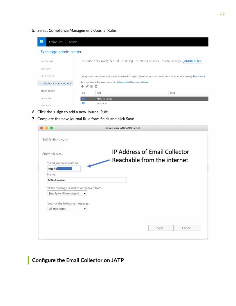
5. Select Compliance Management>Journal Rules.
6. Click the + sign to add a new Journal Rule.
7. Complete the new Journal Rule form fields and click Save.
Configure the Email Collector on JATP
62

1. Login to the JATP Web UI.
2. Navigate to Config>System Profiles> Email Collectors.
3. Under Capture Method, select JATP MTA Receiver.
4. Under MTA Receiver IP, enter the publicly accessible IP address for the JATP MTA appliance.
This is the same address entered at the “Registered app>Home page” step. Note that this deploymentuses DMZ Mode to expose JATP MTA to the service provider allocated public IP address. Portforwarding would be another option.
5. Domains should be left blank.
6. Receive from my email server should be set to No.
7. The Enabled option should be selected.
8. Click Save.
Test the Configuration
1. Login to the JATP Web UI.
2. Navigate to Config>Environmental Settings>Email Mitigation Settings.
3. Click the Test link.
4. Verify that the test is successful.
5. If you see Unable to obtain access token, the manifest file’s key credentials are not correct. This maybe caused by a lack of API access permissions, an incorrect Client ID, or an incorrect Tenant Id. Pleaserefer to the above sections again to verify that all configurations are correct and that they match onboth Azure and JATP.
What to Do Next?
• Navigate to the Configuration tab and select System Settings> Licensing from the left panel; uploadyour license key (obtained from your sales representative).
• Use the Central Manager (CM) Web UI Dashboard and Config pages to confirm traffic monitoring anddetection activity. The CM updates security intelligence every 5 minutes, so you may need to wait 5minutes to see activity at the Web UI.
• Review the Juniper ATP Appliance Product Release Notes for current release information.
• Review the Juniper ATP Appliance Core/Central Manager Quick Start Guide if planning to installadditional Cores, Clustered Cores, Secondary Cores or OVA Cores.
63

• Review the Juniper ATP Appliance vCore for AWS Quick Start Guide if planning to install additionalCores, Clustered Cores, Secondary Cores or OVA Cores.
• Review the Juniper ATP Appliance All-in-One Quick Start Guide for information about All-in-Oneplatform installation and configuration.
• For Email Traffic Collector deployments, refer to the Juniper ATP Appliance Field Guide forinformation about Email Journaling and Gmail BCC configuration.
• Review the Juniper ATP Appliance Web Traffic Collector Quick Start Guide if planning to installadditional or remote Web or Email Traffic Collectors.
• Refer to the Juniper ATP Appliance Mac Mini OS X Engine Quick Start Guide for information aboutinstalling a Mac Mini Detection Engine.
• Refer to the Juniper ATP Appliance CLI Command Reference for information about Collector CLIcommands.
• Refer to the Juniper ATP Appliance Operator’s Guide for information about all products and usage.
• Refer to the Juniper ATP Appliance HTTP API Guide for information about accessing and managingJuniper ATP Appliance advanced threat detection using APIs, including processing data, device andsoftware configuration.
• Refer to the Juniper ATP Appliance CEF Logging Support for SIEM Integration Guide for informationabout CEF logging.
64