MX150 Universal Routing Platform Hardware Guide - juniper.net
130
MX150 Universal Roung Plaorm Hardware Guide Published 2022-01-17
Transcript of MX150 Universal Routing Platform Hardware Guide - juniper.net

MX150 Universal Routing PlatformHardware Guide
Published
2022-01-17

Juniper Networks, Inc.1133 Innovation WaySunnyvale, California 94089USA408-745-2000www.juniper.net
Juniper Networks, the Juniper Networks logo, Juniper, and Junos are registered trademarks of Juniper Networks, Inc.in the United States and other countries. All other trademarks, service marks, registered marks, or registered servicemarks are the property of their respective owners.
Juniper Networks assumes no responsibility for any inaccuracies in this document. Juniper Networks reserves the rightto change, modify, transfer, or otherwise revise this publication without notice.
MX150 Universal Routing Platform Hardware GuideCopyright © 2022 Juniper Networks, Inc. All rights reserved.
The information in this document is current as of the date on the title page.
YEAR 2000 NOTICE
Juniper Networks hardware and software products are Year 2000 compliant. Junos OS has no known time-relatedlimitations through the year 2038. However, the NTP application is known to have some difficulty in the year 2036.
END USER LICENSE AGREEMENT
The Juniper Networks product that is the subject of this technical documentation consists of (or is intended for usewith) Juniper Networks software. Use of such software is subject to the terms and conditions of the End User LicenseAgreement ("EULA") posted at https://support.juniper.net/support/eula/. By downloading, installing or using suchsoftware, you agree to the terms and conditions of that EULA.
ii
Table of Contents
About This Guide | vii
1 Overview
MX150 Router Overview | 2
MX150 Chassis | 4
Chassis Physical Specifications for an MX150 | 4
Front Panel of an MX150 | 5
Rear Panel of an MX150 | 6
Chassis Status LEDs on MX150 | 7
Network Port and Uplink Port LEDs on MX150 | 8
Management Port LEDs on MX150 | 11
MX150 Cooling System | 12
MX150 Power System | 13
Power Supply in MX150 | 13
AC Power Supply Specifications for an MX150 | 13
AC Power Cord Specifications for an MX150 | 14
2 Site Planning, Preparation, and Specifications
Site Preparation Checklist for MX150 | 18
MX150 Site Guidelines and Requirements | 20
General Site Guidelines | 21
Site Electrical Wiring Guidelines | 21
Environmental Requirements and Specifications for an MX150 | 22
Clearance Requirements for Airflow and Hardware Maintenance for an MX150 | 24
Requirements for Mounting an MX150 on a Desktop or Other Level Surface | 25
Cabinet Requirements for an MX150 | 25
iii

Rack Requirements for an MX150 | 26
MX150 Management and Console Port Specifications and Pinouts | 28
Mini-USB Type-B Console Port Specifications for an MX150 | 28
Console Port Connector Pinouts for MX150 | 29
USB Port Specifications for an MX150 | 30
Network Port Connector Pinout Information for an MX150 | 31
RJ-45 to DB-9 Serial Port Adapter Pinout Information for an MX150 | 32
MX150 Network Cable and Transceiver Planning | 33
Pluggable Transceivers Supported on MX150 | 34
SFP+ Direct Attach Copper Cables for MX150 | 35
Cable Specifications for Console and Management Connections for the MX150 | 36
Understanding MX150 Fiber-Optic Cable Signal Loss, Attenuation, and Dispersion | 37
Calculating the Fiber-Optic Cable Power Budget for an MX150 | 39
Calculating the Fiber-Optic Cable Power Margin for an MX150 | 39
3 Initial Installation and Configuration
MX150 Installation Overview | 43
Unpacking and Mounting the MX150 | 43
Unpacking an MX150 | 44
Parts Inventory (Packing List) for an MX150 | 44
Register Products—Mandatory to Validate SLAs | 45
Mounting an MX150 | 46
Mounting an MX150 on a Desk or Other Level Surface | 47
Mounting an MX150 on Two Posts in a Rack | 48
Mounting an MX150 on Four Posts in a Rack or Cabinet | 50
Connecting the MX150 to Power | 53
Connecting Earth Ground to an MX150 | 53
iv

Connecting AC Power to an MX150 | 55
Connecting the MX150 to the Network | 56
Connecting an MX150 to a Management Console | 57
Connecting an MX150 to a Management Console Using Mini-USB Type-B Console Port | 58
Performing the Initial Software Configuration for the MX150 | 60
4 Maintaining Components
Maintaining MX150 Transceivers and Fiber-Optic Cables | 64
Removing a Transceiver from an MX150 | 64
Installing a Transceiver in an MX150 | 66
Maintaining Fiber-Optic Cables in an MX150 | 68
Connecting a Fiber-Optic Cable to an MX150 | 68
Disconnecting a Fiber-Optic Cable from an MX150 | 70
Removing the MX150 | 71
Powering Off an MX150 | 71
Removing an MX150 from a Rack or Cabinet | 73
5 Troubleshooting Hardware
Understanding Alarm Types and Severity Levels on MX150 | 76
6 Contacting Customer Support and Returning the Chassis or Components
Contacting Customer Support and Returning the Chassis or Components | 79
Contacting Customer Support to Obtain a Return Materials Authorization for an MX150 | 79
Locating the Serial Number on an MX150 | 80
Listing the Device and Components Details with the CLI | 80
Locating the Chassis Serial Number ID Label on an MX150 | 81
Packing a MX150 Router or Component for Shipping | 82
Packing an MX150 for Shipping | 82
Packing MX150 Components for Shipping | 83
Returning a MX150 Router or Component for Repair or Replacement | 83
v

7 Safety and Compliance Information
General Safety Guidelines and Warnings | 87
Definitions of Safety Warning Levels | 88
Qualified Personnel Warning | 90
Warning Statement for Norway and Sweden | 90
Fire Safety Requirements | 91
Installation Instructions Warning | 92
Chassis Lifting Guidelines for MX150 | 93
Restricted Access Warning | 93
Ramp Warning | 94
Rack-Mounting and Cabinet-Mounting Warnings | 95
Laser and LED Safety Guidelines and Warnings for the MX150 | 99
Radiation from Open Port Apertures Warning | 104
Maintenance and Operational Safety Guidelines and Warnings | 105
General Electrical Safety Guidelines and Warnings | 111
Action to Take After an Electrical Accident | 113
Prevention of Electrostatic Discharge Damage | 113
AC Power Electrical Safety Guidelines | 115
AC Power Disconnection Warning | 116
TN Power Warning | 117
Agency Approvals for MX150 | 118
Compliance Statements for EMC Requirements for MX150 | 119
vi
About This Guide
Use this guide to install hardware and perform initial software configuration, routine maintenance, andtroubleshooting for the MX150 Universal Routing Platform.
RELATED DOCUMENTATION
MX150 Quick Start
vii
1CHAPTER
Overview
MX150 Router Overview | 2
MX150 Chassis | 4
MX150 Cooling System | 12
MX150 Power System | 13

MX150 Router Overview
IN THIS SECTION
Benefits of MX150 Router | 2
MX150 Hardware | 3
System Software | 4
The MX150 Universal Routing Platform is a compact, high-performance edge router that is ideally suitedfor lower bandwidth service provider applications and distributed service architectures, and forenterprise WAN use-cases. The MX150 supports advanced technologies like telemetry that simplifyyour operations environment, and maximize network uptime.
The MX150 is 1 rack unit (U) tall. The MX150 can be mounted on a desk or any other level surface, ontwo posts in a Rack, and on four pots in a rack or Cabinet. The MX150 conserves space and containscosts associated with power and cooling.
Benefits of MX150 Router
• System Capacity—MX150 provides 20 Gbps of throughput and supports 1-Gigabit Ethernet and 10-Gigabit Ethernet interfaces.
• The Programmable Chipset—The chipset implemented in the MX Series routers has a programmableforwarding data structure that allows fast microcode changes in the hardware itself, and aprogrammable lookup engine that allows inline service processing. the chip’s programmable QoSengine supports coarse and fine-grained queuing to address the requirements of core, edge, andaggregation use cases.
• Always-on infrastructure base—MX Series routers ensure network and service availability with abroad set of multilayered physical, logical, and protocol-level resiliency aspects. Junos OS VirtualChassis technology on MX Series routers supports chassis-level redundancy and enables you tomanage two routers as a single element. Multichassis link aggregation group (MC-LAG)implementation supports stateful chassis, card, and port redundancy.
2
• Application-Aware Networking—On MX Series routers you can use deep packet inspection to detectapplications, and by using the user-defined policies, you can determine traffic treatment for eachapplication. This feature enables highly customized and differentiated services at scale.
• Junos Continuity and Unified In-Service Software Upgrade (Unified ISSU)—With the Junoscontinuity plug-in package, you can perform a smooth upgrade when new hardware is installed inyour MX Series router.
Unified in-service software upgrade (unified ISSU) enables software upgrades and changes withoutdisrupting network traffic.
• Junos Telemetry Interface—Using the Junos telemetry interface data, you can stream component-level data to monitor, analyze, and enhance the performance of the network. Analytics derived fromthis streaming telemetry can identify current and trending congestion, resource utilization, trafficvolume, and buffer occupancy.
• Integrated Hardware-Based Timing— You do not need to use external clocks because MX Seriesrouters support highly scalable and reliable hardware-based timing, including Synchronous Ethernetfor frequency, and the Precision Time Protocol (PTP) for frequency and phase synchronization.Synchronous Ethernet and PTP can be combined in a hybrid mode to achieve a high level offrequency (10 ppb) and phase (<1.5 uS) accuracy.
MX150 Hardware
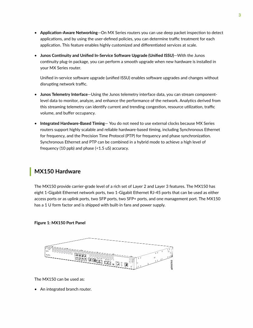
The MX150 provide carrier-grade level of a rich set of Layer 2 and Layer 3 features. The MX150 haseight 1-Gigabit Ethernet network ports, two 1-Gigabit Ethernet RJ-45 ports that can be used as eitheraccess ports or as uplink ports, two SFP ports, two SFP+ ports, and one management port. The MX150has a 1 U form factor and is shipped with built-in fans and power supply.
Figure 1: MX150 Port Panel
The MX150 can be used as:
• An integrated branch router.
3
• A secure router for distributed enterprises.
System Software
The MX150 use the Junos OS CLI. You can manage the device by using the Junos CLI, accessiblethrough the console on the device.
MX150 Chassis
IN THIS SECTION
Chassis Physical Specifications for an MX150 | 4
Front Panel of an MX150 | 5
Rear Panel of an MX150 | 6
Chassis Status LEDs on MX150 | 7
Network Port and Uplink Port LEDs on MX150 | 8
Management Port LEDs on MX150 | 11
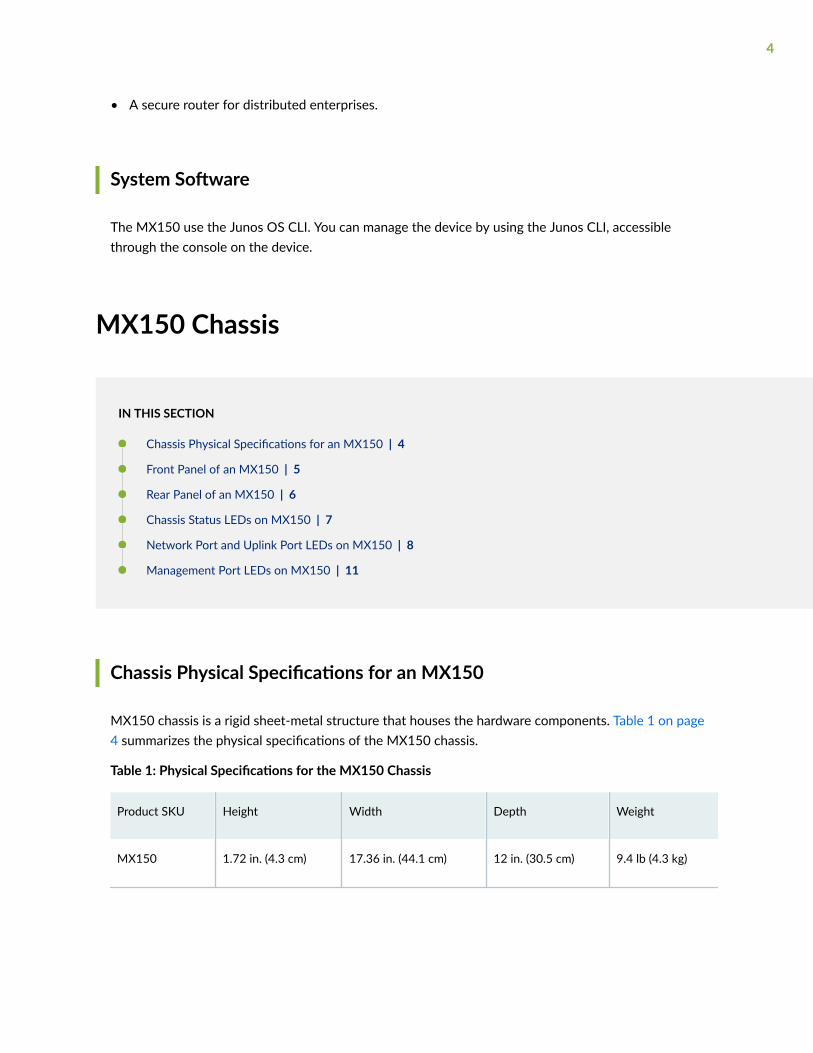
Chassis Physical Specifications for an MX150
MX150 chassis is a rigid sheet-metal structure that houses the hardware components. Table 1 on page4 summarizes the physical specifications of the MX150 chassis.
Table 1: Physical Specifications for the MX150 Chassis
Product SKU Height Width Depth Weight
MX150 1.72 in. (4.3 cm) 17.36 in. (44.1 cm) 12 in. (30.5 cm) 9.4 lb (4.3 kg)
4
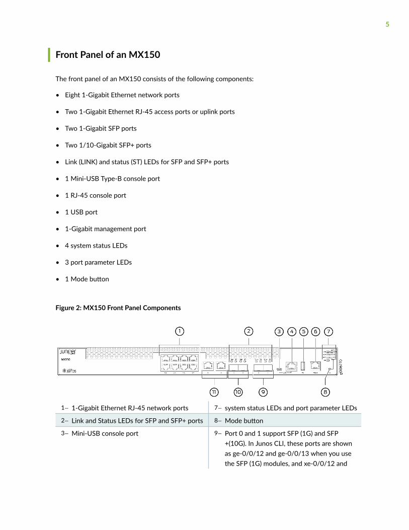
Front Panel of an MX150
The front panel of an MX150 consists of the following components:
• Eight 1-Gigabit Ethernet network ports
• Two 1-Gigabit Ethernet RJ-45 access ports or uplink ports
• Two 1-Gigabit SFP ports
• Two 1/10-Gigabit SFP+ ports
• Link (LINK) and status (ST) LEDs for SFP and SFP+ ports
• 1 Mini-USB Type-B console port
• 1 RJ-45 console port
• 1 USB port
• 1-Gigabit management port
• 4 system status LEDs
• 3 port parameter LEDs
• 1 Mode button
Figure 2: MX150 Front Panel Components
1— 1-Gigabit Ethernet RJ-45 network ports 7— system status LEDs and port parameter LEDs
2— Link and Status LEDs for SFP and SFP+ ports 8— Mode button
3— Mini-USB console port 9— Port 0 and 1 support SFP (1G) and SFP+(10G). In Junos CLI, these ports are shownas ge-0/0/12 and ge-0/0/13 when you usethe SFP (1G) modules, and xe-0/0/12 and
5

xe-0/0/13 when you use the SFP+ (10G)modules.
4— Console (CON) port 10— Port: 10 and 11 support SFP only;
5— USB port 11— 1-Gigabit Ethernet RJ-45 network or uplinkports
6— 1-Gigabit management (mgmt) port
CAUTION: Do not use the Reset button to restart the power sequence unless under thedirection of Juniper Networks Technical Assistance Center (JTAC).
SEE ALSO
Prevention of Electrostatic Discharge Damage
Rear Panel of an MX150
The rear panel of the MX150 consists of the following components (see Figure 3 on page 6):
• Ground area
• Electrostatic discharge (ESD) point
• Exhaust vents
• Power switch
• AC power cord inlet
Figure 3: MX150 Rear Panel
1— Ground area 4— Power switch
2— Electrostatic discharge (ESD) point 5— AC power cord inlet
6
3— Exhaust vents
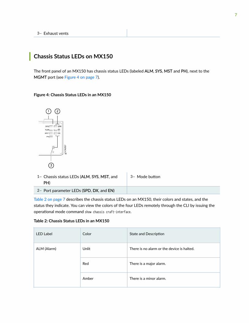
Chassis Status LEDs on MX150
The front panel of an MX150 has chassis status LEDs (labeled ALM, SYS, MST and PH), next to theMGMT port (see Figure 4 on page 7).
Figure 4: Chassis Status LEDs in an MX150
1— Chassis status LEDs (ALM, SYS, MST, andPH)
3— Mode button
2— Port parameter LEDs (SPD, DX, and EN)
Table 2 on page 7 describes the chassis status LEDs on an MX150, their colors and states, and thestatus they indicate. You can view the colors of the four LEDs remotely through the CLI by issuing theoperational mode command show chassis craft-interface.
Table 2: Chassis Status LEDs in an MX150
LED Label Color State and Description
ALM (Alarm) Unlit There is no alarm or the device is halted.
Red There is a major alarm.
Amber There is a minor alarm.
7

Table 2: Chassis Status LEDs in an MX150 (Continued)
LED Label Color State and Description
SYS (System) Green • On steadily—Junos OS has been loaded on thedevice.
• Blinking—The device is booting.
• Off—The device is powered off or is halted.
MST (Primary) Green • On steadily—The device is functioning normally.
• Off—The device is powered off or is halted.
PH Unlit This LED is not used. So, the status of this LED is off.
A major alarm (red) indicates a critical error condition that requires immediate action.
A minor alarm (amber) indicates a noncritical condition that requires monitoring or maintenance. Aminor alarm left unchecked might cause interruption in service or performance degradation.
All three LEDs can be lit simultaneously.
Network Port and Uplink Port LEDs on MX150
Each network port and uplink port on the front panel of an MX150 has two LEDs that indicate linkactivity and port status (see Figure 5 on page 8).
Figure 5: LEDs on the Network Port
8
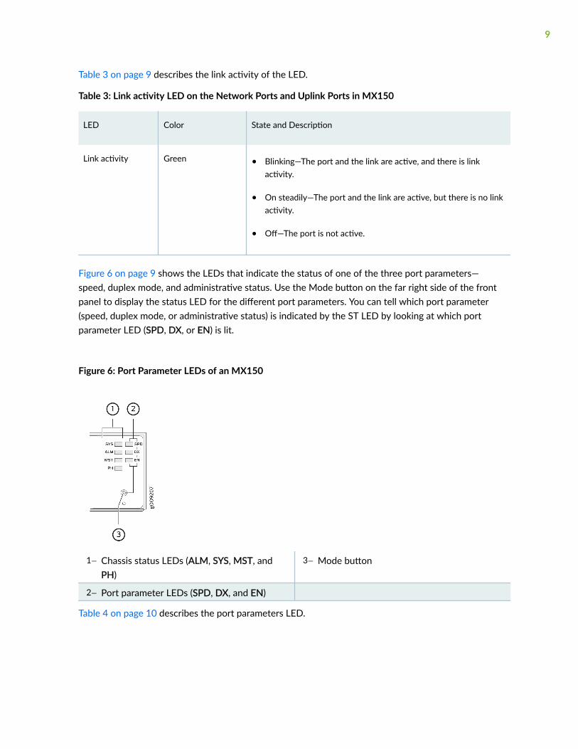
Table 3 on page 9 describes the link activity of the LED.
Table 3: Link activity LED on the Network Ports and Uplink Ports in MX150
LED Color State and Description
Link activity Green • Blinking—The port and the link are active, and there is linkactivity.
• On steadily—The port and the link are active, but there is no linkactivity.
• Off—The port is not active.
Figure 6 on page 9 shows the LEDs that indicate the status of one of the three port parameters—speed, duplex mode, and administrative status. Use the Mode button on the far right side of the frontpanel to display the status LED for the different port parameters. You can tell which port parameter(speed, duplex mode, or administrative status) is indicated by the ST LED by looking at which portparameter LED (SPD, DX, or EN) is lit.
Figure 6: Port Parameter LEDs of an MX150
1— Chassis status LEDs (ALM, SYS, MST, andPH)
3— Mode button
2— Port parameter LEDs (SPD, DX, and EN)
Table 4 on page 10 describes the port parameters LED.
9
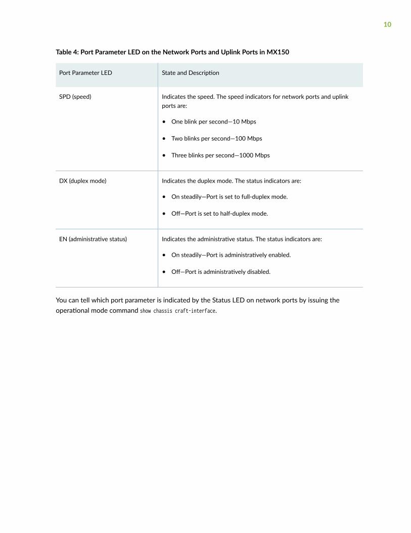
Table 4: Port Parameter LED on the Network Ports and Uplink Ports in MX150
Port Parameter LED State and Description
SPD (speed) Indicates the speed. The speed indicators for network ports and uplinkports are:
• One blink per second—10 Mbps
• Two blinks per second—100 Mbps
• Three blinks per second—1000 Mbps
DX (duplex mode) Indicates the duplex mode. The status indicators are:
• On steadily—Port is set to full-duplex mode.
• Off—Port is set to half-duplex mode.
EN (administrative status) Indicates the administrative status. The status indicators are:
• On steadily—Port is administratively enabled.
• Off—Port is administratively disabled.
You can tell which port parameter is indicated by the Status LED on network ports by issuing theoperational mode command show chassis craft-interface.
10
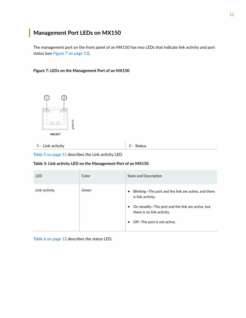
Management Port LEDs on MX150
The management port on the front panel of an MX150 has two LEDs that indicate link activity and portstatus (see Figure 7 on page 11).
Figure 7: LEDs on the Management Port of an MX150
1— Link activity 2— Status
Table 5 on page 11 describes the Link activity LED.
Table 5: Link activity LED on the Management Port of an MX150
LED Color State and Description
Link activity Green • Blinking—The port and the link are active, and thereis link activity.
• On steadily—The port and the link are active, butthere is no link activity.
• Off—The port is not active.
Table 6 on page 12 describes the status LED.
11

Table 6: Status LED on the Management Port of an MX150
LED Color State and Description
Status Green Indicates the speed. The speed indicators are:
• One blink per second—10 Mbps
• Two blinks per second—100 Mbps
• Three blinks per second—1000 Mbps
MX150 Cooling System
The MX150 has front-to-back airflow. The air intake to cool the chassis is located at the front of thechassis. Air is pulled into the chassis and pushed toward the fans, which are built-in. Hot air exhaustsfrom the rear of the chassis. See Figure 8 on page 12.
Figure 8: Front-to-Back Airflow Through the MX150 Chassis
12

RELATED DOCUMENTATION
Prevention of Electrostatic Discharge Damage
MX150 Power System
IN THIS SECTION
Power Supply in MX150 | 13
AC Power Supply Specifications for an MX150 | 13
AC Power Cord Specifications for an MX150 | 14
Power Supply in MX150
The MX150 routers use a fixed, internal AC power supply. The power supply distributes different outputvoltages to the device components according to their voltage requirements. The power supply is fixed inthe chassis and is not field-replaceable.
The power supply has a single AC appliance inlet that requires a dedicated AC power feed. The ACpower cord inlet is on the rear panel of the device.
SEE ALSO
Connecting AC Power to an MX150 | 55
AC Power Supply Specifications for an MX150
Table 7 on page 14 describes the AC power specifications for an MX150.
13

Table 7: AC Power Specifications for an MX150
Item Specification
AC input voltage Operating range:
• 100 through 240 VAC
AC input line frequency 50–60 Hz nominal
AC input current rating 3 A at 240 VAC
Maximum power consumption 140 W
SEE ALSO
General Safety Guidelines and Warnings
General Electrical Safety Guidelines and Warnings
AC Power Cord Specifications for an MX150
A detachable AC power cord is supplied with the AC power supplies. The coupler is type C13 asdescribed by International Electrotechnical Commission (IEC) standard 60320. The plug at the male endof the power cord fits into the power source outlet that is standard for your geographical location.
CAUTION: The AC power cord provided with each power supply is intended for usewith that power supply only and not for any other use.
NOTE: In North America, AC power cords must not exceed 4.5 meters in length, to comply withNational Electrical Code (NEC) Sections 400-8 (NFPA 75, 5-2.2) and 210-52 and CanadianElectrical Code (CEC) Section 4-010(3). The cords supplied with the switch are in compliance.
Table 8 on page 15 gives the AC power cord specifications for the countries and regions listed in thetable.
14
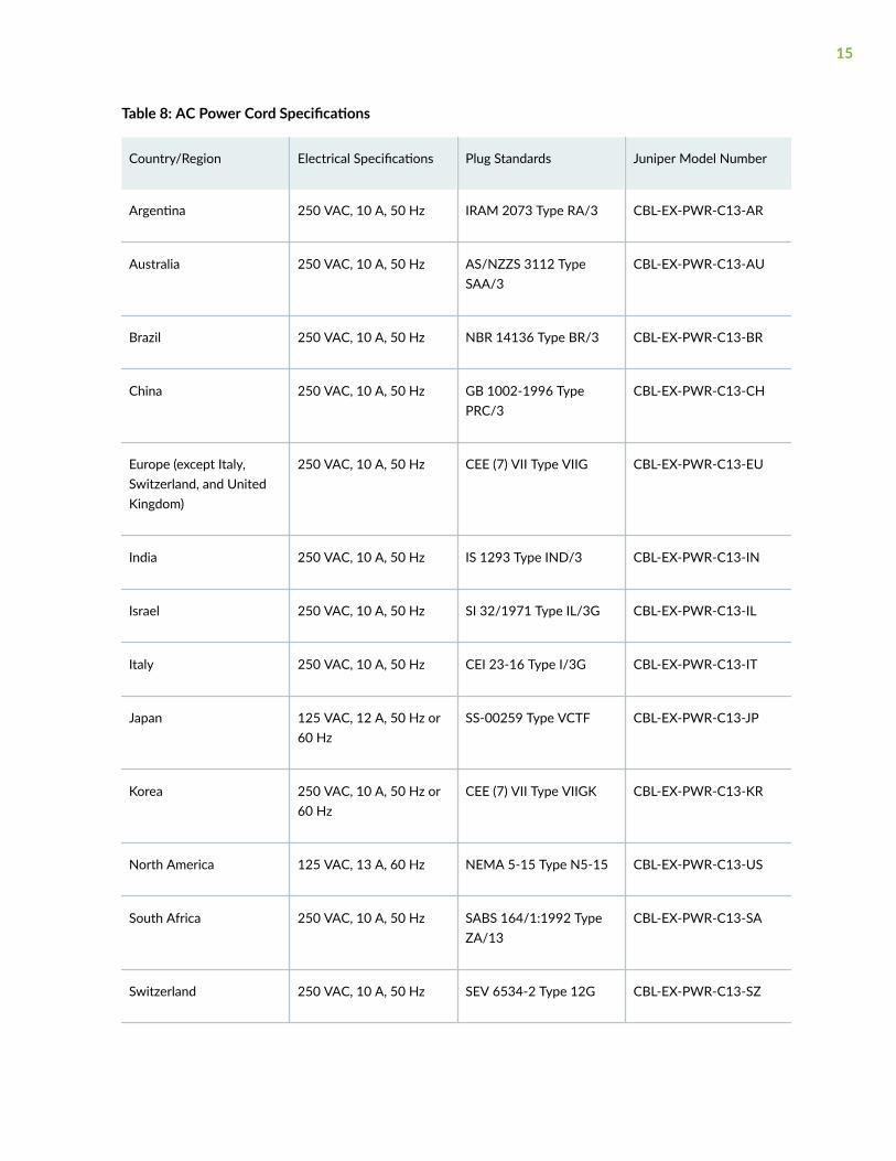
Table 8: AC Power Cord Specifications
Country/Region Electrical Specifications Plug Standards Juniper Model Number
Argentina 250 VAC, 10 A, 50 Hz IRAM 2073 Type RA/3 CBL-EX-PWR-C13-AR
Australia 250 VAC, 10 A, 50 Hz AS/NZZS 3112 TypeSAA/3
CBL-EX-PWR-C13-AU
Brazil 250 VAC, 10 A, 50 Hz NBR 14136 Type BR/3 CBL-EX-PWR-C13-BR
China 250 VAC, 10 A, 50 Hz GB 1002-1996 TypePRC/3
CBL-EX-PWR-C13-CH
Europe (except Italy,Switzerland, and UnitedKingdom)
250 VAC, 10 A, 50 Hz CEE (7) VII Type VIIG CBL-EX-PWR-C13-EU
India 250 VAC, 10 A, 50 Hz IS 1293 Type IND/3 CBL-EX-PWR-C13-IN
Israel 250 VAC, 10 A, 50 Hz SI 32/1971 Type IL/3G CBL-EX-PWR-C13-IL
Italy 250 VAC, 10 A, 50 Hz CEI 23-16 Type I/3G CBL-EX-PWR-C13-IT
Japan 125 VAC, 12 A, 50 Hz or60 Hz
SS-00259 Type VCTF CBL-EX-PWR-C13-JP
Korea 250 VAC, 10 A, 50 Hz or60 Hz
CEE (7) VII Type VIIGK CBL-EX-PWR-C13-KR
North America 125 VAC, 13 A, 60 Hz NEMA 5-15 Type N5-15 CBL-EX-PWR-C13-US
South Africa 250 VAC, 10 A, 50 Hz SABS 164/1:1992 TypeZA/13
CBL-EX-PWR-C13-SA
Switzerland 250 VAC, 10 A, 50 Hz SEV 6534-2 Type 12G CBL-EX-PWR-C13-SZ
15
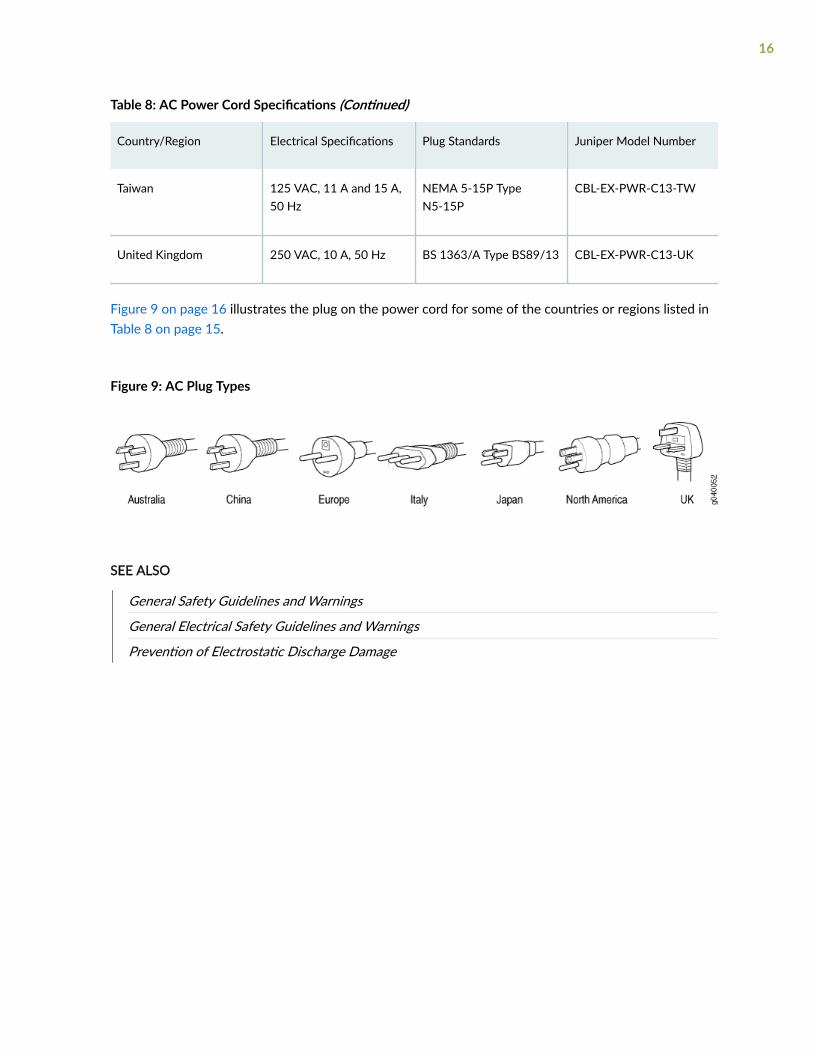
Table 8: AC Power Cord Specifications (Continued)
Country/Region Electrical Specifications Plug Standards Juniper Model Number
Taiwan 125 VAC, 11 A and 15 A,50 Hz
NEMA 5-15P TypeN5-15P
CBL-EX-PWR-C13-TW
United Kingdom 250 VAC, 10 A, 50 Hz BS 1363/A Type BS89/13 CBL-EX-PWR-C13-UK
Figure 9 on page 16 illustrates the plug on the power cord for some of the countries or regions listed inTable 8 on page 15.
Figure 9: AC Plug Types
SEE ALSO
General Safety Guidelines and Warnings
General Electrical Safety Guidelines and Warnings
Prevention of Electrostatic Discharge Damage
16

2CHAPTER
Site Planning, Preparation, andSpecifications
Site Preparation Checklist for MX150 | 18
MX150 Site Guidelines and Requirements | 20
MX150 Management and Console Port Specifications and Pinouts | 28
MX150 Network Cable and Transceiver Planning | 33

Site Preparation Checklist for MX150
The checklist in Table 9 on page 18 summarizes the tasks you need to perform when preparing a sitefor MX150 router installation.
Table 9: Site Preparation Checklist
Item or Task For More Information Performed by Date
Environment
Verify that environmental factors such astemperature and humidity do not exceeddevice tolerances.
"Environmental Requirementsand Specifications for an MX150"on page 22
Power
Measure distance between external powersources and device installation site.
Locate sites for connection of systemgrounding.
Calculate the power consumption andrequirements.
"AC Power Supply Specificationsfor an MX150" on page 13
Hardware Configuration
Choose the number of devices you wantto install.
"MX150 Router Overview" onpage 2
Rack or Cabinet
Verify that your rack or cabinet meets theminimum requirements for the installationof the device.
"Rack Requirements for anMX150" on page 26
"Cabinet Requirements for anMX150" on page 25
18
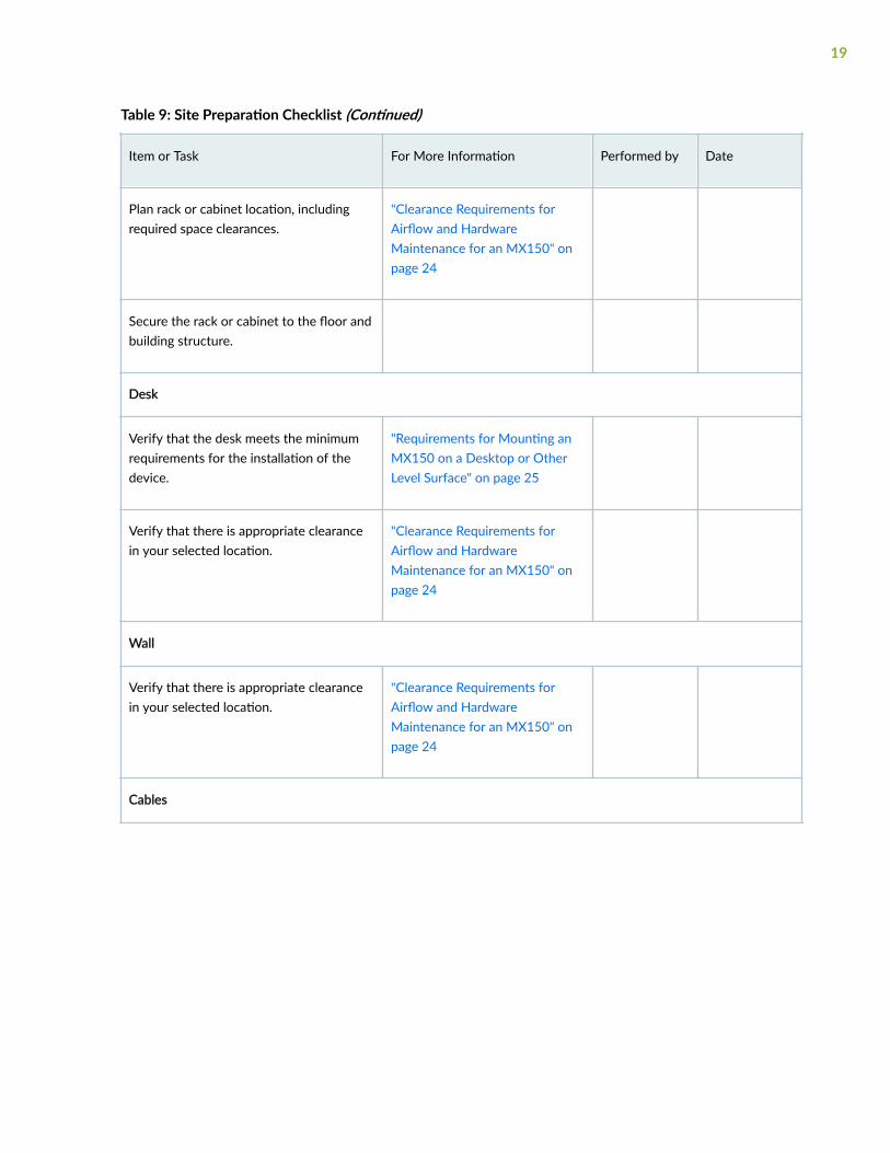
Table 9: Site Preparation Checklist (Continued)
Item or Task For More Information Performed by Date
Plan rack or cabinet location, includingrequired space clearances.
"Clearance Requirements forAirflow and HardwareMaintenance for an MX150" onpage 24
Secure the rack or cabinet to the floor andbuilding structure.
Desk
Verify that the desk meets the minimumrequirements for the installation of thedevice.
"Requirements for Mounting anMX150 on a Desktop or OtherLevel Surface" on page 25
Verify that there is appropriate clearancein your selected location.
"Clearance Requirements forAirflow and HardwareMaintenance for an MX150" onpage 24
Wall
Verify that there is appropriate clearancein your selected location.
"Clearance Requirements forAirflow and HardwareMaintenance for an MX150" onpage 24
Cables
19
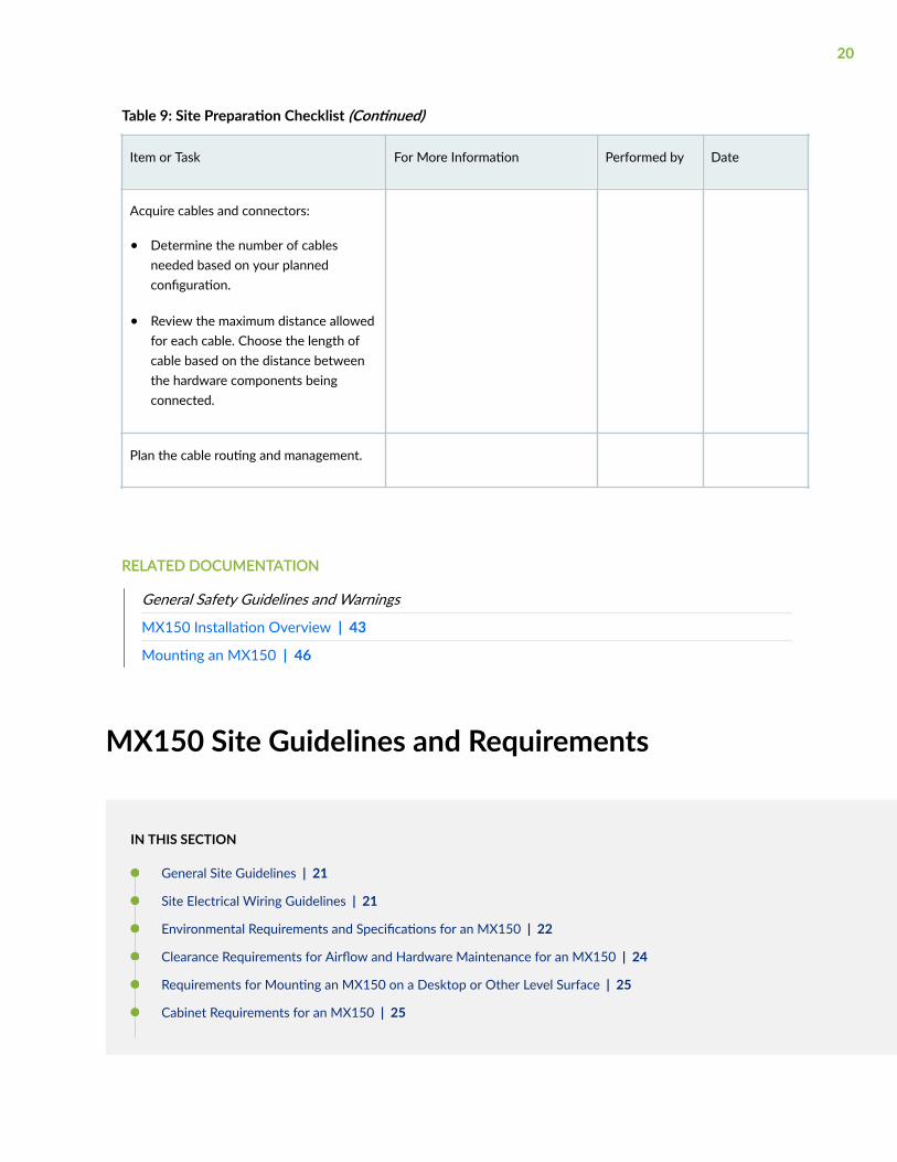
Table 9: Site Preparation Checklist (Continued)
Item or Task For More Information Performed by Date
Acquire cables and connectors:
• Determine the number of cablesneeded based on your plannedconfiguration.
• Review the maximum distance allowedfor each cable. Choose the length ofcable based on the distance betweenthe hardware components beingconnected.
Plan the cable routing and management.
RELATED DOCUMENTATION
General Safety Guidelines and Warnings
MX150 Installation Overview | 43
Mounting an MX150 | 46
MX150 Site Guidelines and Requirements
IN THIS SECTION
General Site Guidelines | 21
Site Electrical Wiring Guidelines | 21
Environmental Requirements and Specifications for an MX150 | 22
Clearance Requirements for Airflow and Hardware Maintenance for an MX150 | 24
Requirements for Mounting an MX150 on a Desktop or Other Level Surface | 25
Cabinet Requirements for an MX150 | 25
20
Rack Requirements for an MX150 | 26
General Site Guidelines
Efficient device operation requires proper site planning and maintenance and proper layout of theequipment, rack or cabinet, and wiring closet.
To plan and create an acceptable operating environment for your device and prevent environmentallycaused equipment failures:
• Keep the area around the chassis free from dust and conductive material, such as metal flakes.
• Follow prescribed airflow guidelines to ensure that the cooling system functions properly and thatexhaust from other equipment does not blow into the intake vents of the device.
• Follow the prescribed electrostatic discharge (ESD) prevention procedures to prevent damaging theequipment. Static discharge can cause components to fail completely or intermittently over time.
• Install the device in a secure area, so that only authorized personnel can access the device.
Site Electrical Wiring Guidelines
Table 10 on page 22 describes the factors you must consider while planning the electrical wiring atyour site.
WARNING: You must provide a properly grounded and shielded environment and useelectrical surge-suppression devices.
Avertissement Vous devez établir un environnement protégé et convenablement mis àla terre et utiliser des dispositifs de parasurtension.
21

Table 10: Site Electrical Wiring Guidelines
Site WiringFactor
Guidelines
Signalinglimitations
If your site experiences any of the following problems, consult experts in electrical surgesuppression and shielding:
• Improperly installed wires cause radio frequency interference (RFI).
• Damage from lightning strikes occurs when wires exceed recommended distances or passbetween buildings.
• Electromagnetic pulses (EMPs) caused by lightning damage unshielded conductors andelectronic devices.
Radiofrequencyinterference
To reduce or eliminate RFI from your site wiring, do the following:
• Use a twisted-pair cable with a good distribution of grounding conductors.
• If you must exceed the recommended distances, use a high-quality twisted-pair cable withone ground conductor for each data signal, when applicable.
Electromagneticcompatibility
If your site is susceptible to problems with electromagnetic compatibility (EMC), particularlyfrom lightning or radio transmitters, seek expert advice.
Some of the problems caused by strong sources of electromagnetic interference (EMI) are:
• Destruction of the signal drivers and receivers in the device
• Electrical hazards as a result of power surges conducted over the lines into the equipment
Environmental Requirements and Specifications for an MX150
The MX150 must be installed in a rack or cabinet. It must be housed in a dry, clean, well-ventilated, andtemperature-controlled environment.
Follow these environmental guidelines:
• The site must be as dust-free as possible, because dust can clog air intake vents and filters, reducingthe efficiency of the device cooling system.
22
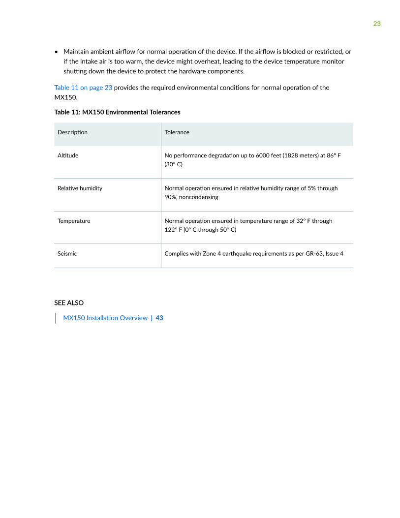
• Maintain ambient airflow for normal operation of the device. If the airflow is blocked or restricted, orif the intake air is too warm, the device might overheat, leading to the device temperature monitorshutting down the device to protect the hardware components.
Table 11 on page 23 provides the required environmental conditions for normal operation of theMX150.
Table 11: MX150 Environmental Tolerances
Description Tolerance
Altitude No performance degradation up to 6000 feet (1828 meters) at 86° F(30° C)
Relative humidity Normal operation ensured in relative humidity range of 5% through90%, noncondensing
Temperature Normal operation ensured in temperature range of 32° F through122° F (0° C through 50° C)
Seismic Complies with Zone 4 earthquake requirements as per GR-63, Issue 4
SEE ALSO
MX150 Installation Overview | 43
23

Clearance Requirements for Airflow and Hardware Maintenance for anMX150
When planning the site for installing an MX150, you must allow sufficient clearance around the installedchassis (see Figure 10 on page 24).
Figure 10: Clearance Requirements for Airflow and Hardware Maintenance for an MX150
• For the cooling system to function properly, the airflow around the chassis must be unrestricted. See"MX150 Cooling System" on page 12 for more information about the airflow through the chassis.
• If you are mounting an MX150 in a rack or cabinet with other equipment, ensure that the exhaustfrom other equipment does not blow into the intake vents of the chassis.
• Leave at least 24 in. (61 cm) both in front of and behind the MX150. For service personnel to removeand install hardware components, you must leave adequate space at the front and back of theMX150. NEBS GR-63 recommends that you allow at least 30 in. (76.2 cm) in front of the rack orcabinet and 24 in. (61 cm) behind the rack or cabinet.
24

SEE ALSO
Rack-Mounting and Cabinet-Mounting Warnings
Requirements for Mounting an MX150 on a Desktop or Other LevelSurface
You can install the MX150 on a desktop or other such level surface, by attaching the four rubber feet(provided) to the bottom of the chassis.
When choosing a location, allow at least 6 in. (15.2 cm) of clearance between the front and back of thechassis and adjacent equipment or walls.
Ensure that the desktop or other level surface on which the device is installed is stable and securelysupported.
Cabinet Requirements for an MX150
You can mount the MX150 in an enclosure or cabinet that contains a four-post 19-in. open rack asdefined in Cabinets, Racks, Panels, and Associated Equipment (document number EIA-310-D) publishedby the Electronics Industry Association.
Cabinet requirements consist of:
• Cabinet size and clearance
• Cabinet airflow requirements
Table 12 on page 25 provides the cabinet requirements and specifications for the MX150.
Table 12: Cabinet Requirements for the MX150
Cabinet Requirement Guidelines
Cabinet size and clearance The minimum cabinet size for accommodating an MX150 is 36 in.(91.4 cm) deep. Large cabinets improve airflow and reduce the chance ofoverheating.
25

Table 12: Cabinet Requirements for the MX150 (Continued)
Cabinet Requirement Guidelines
Cabinet airflow requirements When you mount the switch in a cabinet, ensure that ventilation throughthe cabinet is sufficient to prevent overheating.
• Ensure that the cool air supply you provide through the cabinetadequately dissipates the thermal output of the switch (or switches).
• Ensure that the cabinet allows the chassis hot exhaust air to exit thecabinet without recirculating into the switch. An open cabinet(without a top or doors) that employs hot air exhaust extraction fromthe top allows the best airflow through the chassis. If the cabinetcontains a top or doors, perforations in these elements assist withremoving the hot air exhaust.
• Install the switch in the cabinet in a way that maximizes the openspace on the side of the chassis that has the hot air exhaust.
• Route and dress all cables to minimize the blockage of airflow to andfrom the chassis.
• Ensure that the spacing of rails and adjacent cabinets allows for theproper clearance around the switch and cabinet.
• A cabinet larger than the minimum required provides better airflowand reduces the chance of overheating.
Rack Requirements for an MX150
You can mount the MX150 on two-post racks or four-post racks.
Rack requirements consist of:
• Rack type
• Mounting bracket hole spacing
• Rack size and strength
• Rack connection to the building structure
Table 13 on page 27 provides the rack requirements and specifications for the MX150.
26

Table 13: Rack Requirements and Specifications for the MX150
Rack Requirement Guidelines
Rack type Use a two-post rack or a four-post rack. You can mount the device on any two-post or four-post rack that provides bracket holes or hole patterns spaced at 1 U (1.75 in. or 4.45 cm)increments and that meets the size and strength requirements to support the weight.
A U is the standard rack unit defined in Cabinets, Racks, Panels, and Associated Equipment(document number EIA-310–D) published by the Electronics Industry Association (http://www.ecianow.org/standards-practices/standards/).
The rack must meet the strength requirements to support the weight of the chassis.
Mounting brackethole spacing
The holes in the mounting brackets are spaced at 1 U (1.75 in. or 4.45 cm), so that thedevice can be mounted in any rack that provides holes spaced at that distance.
Rack size andstrength
• Ensure that the rack complies with the standard defined for 19-in. rack as defined inCabinets, Racks, Panels, and Associated Equipment (document number EIA-310–D)published by the Electronics Industry Association (http://www.ecianow.org/standards-practices/standards/).
• Ensure that the rack rails are spaced widely enough to accommodate the device chassis'external dimensions of 1.72 in. (4.3 cm) height, 17.36 in. (44.1 cm) width, and 12 in.(30.5 cm) depth. The 19-in. rack brackets dimensions are 0.82 in. (2.1 cm) wide, 1.72 in.(4.3 cm) height, and 2.1 in. (5.4 cm) depth. The 23-in. rack brackets dimensions are 3.3 in.(8.4 cm) wide, 1.72 in. (4.3 cm) height, and 8.5 in. (21.6 cm) depth.
• The rack must be strong enough to support the weight of the device.
• Ensure that the spacing of rails and adjacent racks allows for the proper clearancearound the device and rack.
Rack connectionto buildingstructure
• Secure the rack to the building structure.
• If earthquakes are a possibility in your geographical area, secure the rack to the floor.
• Secure the rack to the ceiling brackets as well as wall or floor brackets for maximumstability.
One pair of mounting brackets for mounting the device on two posts of a rack is supplied with eachdevice. For mounting the device on four posts of a rack or cabinet, you can order a four-post rack-mountkit separately.
27

SEE ALSO
Rack-Mounting and Cabinet-Mounting Warnings
Mounting an MX150 on Two Posts in a Rack | 48
Mounting an MX150 on Four Posts in a Rack or Cabinet | 50
MX150 Management and Console PortSpecifications and Pinouts
IN THIS SECTION
Mini-USB Type-B Console Port Specifications for an MX150 | 28
Console Port Connector Pinouts for MX150 | 29
USB Port Specifications for an MX150 | 30
Network Port Connector Pinout Information for an MX150 | 31
RJ-45 to DB-9 Serial Port Adapter Pinout Information for an MX150 | 32
Mini-USB Type-B Console Port Specifications for an MX150
The MX150 has two console ports: an RJ-45 port, and a Mini-USB port.
By default, the RJ-45 port is set as the active console port. It can display all the early boot and low-levelmessage output and you can access the device through this port in the debugger prompt.
The Mini-USB port is the passive console port. You can change the status of the port to active or passiveusing the port-type configuration statement. See Configuring the Console Port Type (CLI Procedure).
The Mini-USB console port uses a Mini-B plug (5-pin) connector to connect to a console managementdevice. The default baud rate for the console port is 9600 baud.
Table 14 on page 29 provides the pinout information of the Mini-USB Type-B console port.
28

Table 14: Mini-USB Type-B Console Port Pinout Information for MX150
Pin Signal Description
1 VCC +5 VDC
2 D- Data -
3 D+ Data +
X N/C N/C, GND, or used as an attached device presence indicator
4 GND Ground
SEE ALSO
MX150 Router Overview | 2
Configuring the Console Port Type (CLI Procedure)
Console Port Connector Pinouts for MX150
The console port (labeled CON) is an RS-232 serial interface that uses an RJ-45 connector to connect toa console management device. The default baud rate for the console port is 9600 baud.
Table 15 on page 30 provides the pinout information for the RJ-45 console connector. An RJ-45 cableand RJ-45 to DB-9 adapter are supplied with the MX150 device.
NOTE: If your laptop or PC does not have a DB-9 plug connector pin and you want to connectyour laptop or PC directly to an MX150 device, use a combination of the RJ-45 cable and RJ-45to DB-9 adapter supplied with the device and a USB to DB-9 plug adapter. You must provide theUSB to DB-9 plug adapter.
29

Table 15: Console Port Connector Pinouts for the MX150
Pin Signal Description
1 RTS Output Request to send
2 DTR Output Data terminal ready
3 TxD Output Transmit data
4 Signal Ground Signal ground
5 Signal Ground Signal ground
6 RxD Input Receive data
7 DCD Input Data carrier detect
8 CTS Input Clear to send
SEE ALSO
Connecting an MX150 to a Management Console | 57
USB Port Specifications for an MX150
The following Juniper Networks USB flash drives have been tested and are officially supported for theUSB port in the MX150:
• RE-USB-1G-S—1-gigabyte (GB) USB flash drive
• RE-USB-2G-S—2-GB USB flash drive
• RE-USB-4G-S—4-GB USB flash drive
30
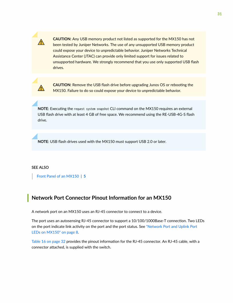
CAUTION: Any USB memory product not listed as supported for the MX150 has notbeen tested by Juniper Networks. The use of any unsupported USB memory productcould expose your device to unpredictable behavior. Juniper Networks TechnicalAssistance Center (JTAC) can provide only limited support for issues related tounsupported hardware. We strongly recommend that you use only supported USB flashdrives.
CAUTION: Remove the USB flash drive before upgrading Junos OS or rebooting theMX150. Failure to do so could expose your device to unpredictable behavior.
NOTE: Executing the request system snapshot CLI command on the MX150 requires an externalUSB flash drive with at least 4 GB of free space. We recommend using the RE-USB-4G-S flashdrive.
NOTE: USB flash drives used with the MX150 must support USB 2.0 or later.
SEE ALSO
Front Panel of an MX150 | 5
Network Port Connector Pinout Information for an MX150
A network port on an MX150 uses an RJ-45 connector to connect to a device.
The port uses an autosensing RJ-45 connector to support a 10/100/1000Base-T connection. Two LEDson the port indicate link activity on the port and the port status. See "Network Port and Uplink PortLEDs on MX150" on page 8.
Table 16 on page 32 provides the pinout information for the RJ-45 connector. An RJ-45 cable, with aconnector attached, is supplied with the switch.
31
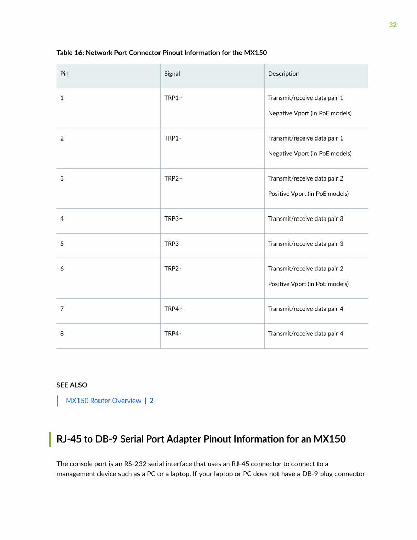
Table 16: Network Port Connector Pinout Information for the MX150
Pin Signal Description
1 TRP1+ Transmit/receive data pair 1
Negative Vport (in PoE models)
2 TRP1- Transmit/receive data pair 1
Negative Vport (in PoE models)
3 TRP2+ Transmit/receive data pair 2
Positive Vport (in PoE models)
4 TRP3+ Transmit/receive data pair 3
5 TRP3- Transmit/receive data pair 3
6 TRP2- Transmit/receive data pair 2
Positive Vport (in PoE models)
7 TRP4+ Transmit/receive data pair 4
8 TRP4- Transmit/receive data pair 4
SEE ALSO
MX150 Router Overview | 2
RJ-45 to DB-9 Serial Port Adapter Pinout Information for an MX150
The console port is an RS-232 serial interface that uses an RJ-45 connector to connect to amanagement device such as a PC or a laptop. If your laptop or PC does not have a DB-9 plug connector
32

pin and you want to connect your laptop or PC to an MX150, use a combination of the RJ-45 to DB-9socket adapter supplied with the switch along with a USB to DB-9 plug adapter.
Table 17 on page 33 provides the pinout information for the RJ-45 to DB-9 serial port adapter.
Table 17: RJ-45 to DB-9 Serial Port Adapter Pinout Information
RJ-45 Pin Signal DB-9 Pin Signal
1 RTS 8 CTS
2 DTR 6 DSR
3 TXD 2 RXD
4 GND 5 GND
6 RXD 3 TXD
7 DSR 4 DTR
8 CTS 7 RTS
SEE ALSO
Connecting an MX150 to a Management Console | 57
MX150 Network Cable and Transceiver Planning
IN THIS SECTION
Pluggable Transceivers Supported on MX150 | 34
33

SFP+ Direct Attach Copper Cables for MX150 | 35
Cable Specifications for Console and Management Connections for the MX150 | 36
Understanding MX150 Fiber-Optic Cable Signal Loss, Attenuation, and Dispersion | 37
Calculating the Fiber-Optic Cable Power Budget for an MX150 | 39
Calculating the Fiber-Optic Cable Power Margin for an MX150 | 39
Pluggable Transceivers Supported on MX150
Uplink ports on MX150 support SFP and SFP+ transceivers. This topic describes the optical interfacessupported for those transceivers. It also lists the copper interface supported for the SFP transceivers.
NOTE: We recommend that you use only optical transceivers and optical connectors purchasedfrom Juniper Networks with your Juniper Networks device.
CAUTION: If you face a problem running a Juniper Networks device that uses a third-party optic or cable, the Juniper Networks Technical Assistance Center (JTAC) can helpyou diagnose the source of the problem. Your JTAC engineer might recommend thatyou check the third-party optic or cable and potentially replace it with an equivalentJuniper Networks optic or cable that is qualified for the device.
NOTE: You can use the Hardware Compatibility Tool to find information about the pluggabletransceivers supported on your Juniper Networks device.
The list of supported transceivers for the MX Series is located at https://pathfinder.juniper.net/hct/category/#catKey=100001&modelType;=All&pf;=MX+Series.
SEE ALSO
Front Panel of an MX150 | 5
Installing a Transceiver in an MX150 | 66
Removing a Transceiver from an MX150 | 64
34

SFP+ Direct Attach Copper Cables for MX150
IN THIS SECTION
Cable Specifications | 35
Standards Supported by These Cables | 36
Small form-factor pluggable plus transceiver (SFP+) direct attach copper (DAC) cables, also known asTwinax cables, are suitable for in-rack connections between servers and switches. They are suitable forshort distances of up to 23 ft, making them ideal for highly cost-effective networking connectivitywithin a rack and between adjacent racks.
This topic describes:
Cable Specifications
MX150 routers support SFP+ passive DAC cables. The passive Twinax cable is a straight cable with noactive electronic components. MX150 routers support 1 m, 3 m, and 5 m long SFP+ passive DAC cables.
NOTE: We recommend that you use only SFP+ DAC cables purchased from Juniper Networkswith your Juniper Networks device.
CAUTION: If you face a problem running a Juniper Networks device that uses a third-party optic or cable, the Juniper Networks Technical Assistance Center (JTAC) can helpyou diagnose the source of the problem. Your JTAC engineer might recommend thatyou check the third-party optic or cable and potentially replace it with an equivalentJuniper Networks optic or cable that is qualified for the device.
The cables are hot-removable and hot-insertable: You can remove and replace them without poweringoff the switch or disrupting switch functions. A cable comprises a low-voltage cable assembly thatconnects directly into two SFP+ ports, one at each end of the cable. The cables use high-performanceintegrated duplex serial data links for bidirectional communication and are designed for data rates of upto 10 Gbps.
35

NOTE: You can use the Hardware Compatibility Tool to find information about the cablessupported on your Juniper Networks device.
The list of supported transceivers for the MX Series is located at https://pathfinder.juniper.net/hct/category/#catKey=100001&modelType;=All&pf;=MX+Series.
Standards Supported by These Cables
The cables comply with the following standards:
• SFP mechanical standard SFF-843—see ftp://ftp.seagate.com/sff/SFF-8431.PDF .
• Electrical interface standard SFF-8432—see ftp://ftp.seagate.com/sff/SFF-8432.PDF .
• SFP+ Multi-Source Alliance (MSA) standards
SEE ALSO
Installing a Transceiver in an MX150 | 66
Removing a Transceiver from an MX150 | 64
Cable Specifications for Console and Management Connections for theMX150
Table 18 on page 36 lists the specifications for the cables that connect the MX150 to a managementdevice.
Table 18: Cable Specifications for Console and Management Connections for the MX150
Port on MX150Device
Cable Specification Cable Supplied MaximumLength
DeviceReceptacle
Console port RS-232 (EIA-232) serialcable
One 2.13-meter-longRJ-45 patch cable andRJ-45 to DB-9 adapter
2.13 meters RJ-45
36

Table 18: Cable Specifications for Console and Management Connections for the MX150 (Continued)
Port on MX150Device
Cable Specification Cable Supplied MaximumLength
DeviceReceptacle
Management port Category 5 cable orequivalent suitable for1000BASE-T operation
One 2.13-meter-longRJ-45 patch cable
2.13 meters RJ-45
SEE ALSO
Connecting an MX150 to a Management Console | 57
Understanding MX150 Fiber-Optic Cable Signal Loss, Attenuation, andDispersion
IN THIS SECTION
Signal Loss in Multimode and Single-Mode Fiber-Optic Cables | 37
Attenuation and Dispersion in Fiber-Optic Cable | 38
To determine the power budget and power margin needed for fiber-optic connections, you need tounderstand how signal loss, attenuation, and dispersion affect transmission. The MX150 uses varioustypes of network cable, including multimode and single-mode fiber-optic cables.
Signal Loss in Multimode and Single-Mode Fiber-Optic Cables
Multimode fiber is large enough in diameter to allow rays of light to reflect internally (bounce off thewalls of the fiber). Interfaces with multimode optics typically use LEDs as light sources. However, LEDsare not coherent light sources. They spray varying wavelengths of light into the multimode fiber, whichreflects the light at different angles. Light rays travel in jagged lines through a multimode fiber, causingsignal dispersion. When light traveling in the fiber core radiates into the fiber cladding (layers of lowerrefractive index material in close contact with a core material of higher refractive index), higher-order
37
mode loss occurs. Together, these factors reduce the transmission distance of multimode fiber comparedto that of single-mode fiber.
Single-mode fiber is so small in diameter that rays of light reflect internally through one layer only.Interfaces with single-mode optics use lasers as light sources. Lasers generate a single wavelength oflight, which travels in a straight line through the single-mode fiber. Compared to multimode fiber, single-mode fiber has a higher bandwidth and can carry signals for longer distances. It is consequently moreexpensive.
For information about the maximum transmission distance and supported wavelength range for thetypes of single-mode and multimode fiber-optic cables that are connected to the MX150, see "PluggableTransceivers Supported on MX150" on page 34. Exceeding the maximum transmission distances canresult in significant signal loss, which causes unreliable transmission.
Attenuation and Dispersion in Fiber-Optic Cable
An optical data link functions correctly provided that modulated light reaching the receiver has enoughpower to be demodulated correctly. Attenuation is the reduction in strength of the light signal duringtransmission. Passive media components such as cables, cable splices, and connectors causeattenuation. Although attenuation is significantly lower for optical fiber than for other media, it stilloccurs in both multimode and single-mode transmission. An efficient optical data link must transmitenough light to overcome attenuation.
Dispersion is the spreading of the signal over time. The following two types of dispersion can affectsignal transmission through an optical data link:
• Chromatic dispersion, which is the spreading of the signal over time caused by the different speedsof light rays.
• Modal dispersion, which is the spreading of the signal over time caused by the different propagationmodes in the fiber.
For multimode transmission, modal dispersion, rather than chromatic dispersion or attenuation, usuallylimits the maximum bit rate and link length. For single-mode transmission, modal dispersion is not afactor. However, at higher bit rates and over longer distances, chromatic dispersion limits the maximumlink length.
An efficient optical data link must have enough light to exceed the minimum power that the receiverrequires to operate within its specifications. In addition, the total dispersion must be within the limitsspecified for the type of link in Telcordia Technologies document GR-253-CORE (Section 4.3) andInternational Telecommunications Union (ITU) document G.957.
When chromatic dispersion is at the maximum allowed, its effect can be considered as a power penaltyin the power budget. The optical power budget must allow for the sum of component attenuation,power penalties (including those from dispersion), and a safety margin for unexpected losses.
38

Calculating the Fiber-Optic Cable Power Budget for an MX150
Calculate the link's power budget when planning fiber-optic cable layout and distances to ensure thatfiber-optic connections have sufficient power for correct operation. The power budget is the maximumamount of power the link can transmit. When you calculate the power budget, you use a worst-caseanalysis to provide a margin of error, even though all the parts of an actual system do not operate at theworst-case levels.
To calculate the worst-case estimate for fiber-optic cable power budget (PB) for the link:
1. Determine values for the link's minimum transmitter power (PT) and minimum receiver sensitivity(PR). For example, here, (PT) and (PR) are measured in decibels, and decibels are referenced to 1milliwatt (dBm).
PT = –15 dBm
PR = –28 dBm
NOTE: See the specifications for your transmitter and receiver to find the minimumtransmitter power and minimum receiver sensitivity.
2. Calculate the power budget (PB) by subtracting (PR) from (PT):
–15 dBm – (–28 dBm) = 13 dBm
Calculating the Fiber-Optic Cable Power Margin for an MX150
Before you begin to calculate the power margin:
• Calculate the power budget. See "Calculating the Fiber-Optic Cable Power Budget for an MX150" onpage 39.
Calculate the link's power margin when planning fiber-optic cable layout and distances to ensure thatfiber-optic connections have sufficient signal power to overcome system losses and still satisfy theminimum input requirements of the receiver for the required performance level. The power margin (PM )is the amount of power available after attenuation or link loss (LL) has been subtracted from the powerbudget (PB).
When you calculate the power margin, you use a worst-case analysis to provide a margin of error, eventhough all the parts of an actual system do not operate at worst-case levels. A power margin (PM )greater than zero indicates that the power budget is sufficient to operate the receiver and that it doesnot exceed the maximum receiver input power. This means the link will work. A (PM) that is zero or
39
negative indicates insufficient power to operate the receiver. See the specification for your receiver tofind the maximum receiver input power.
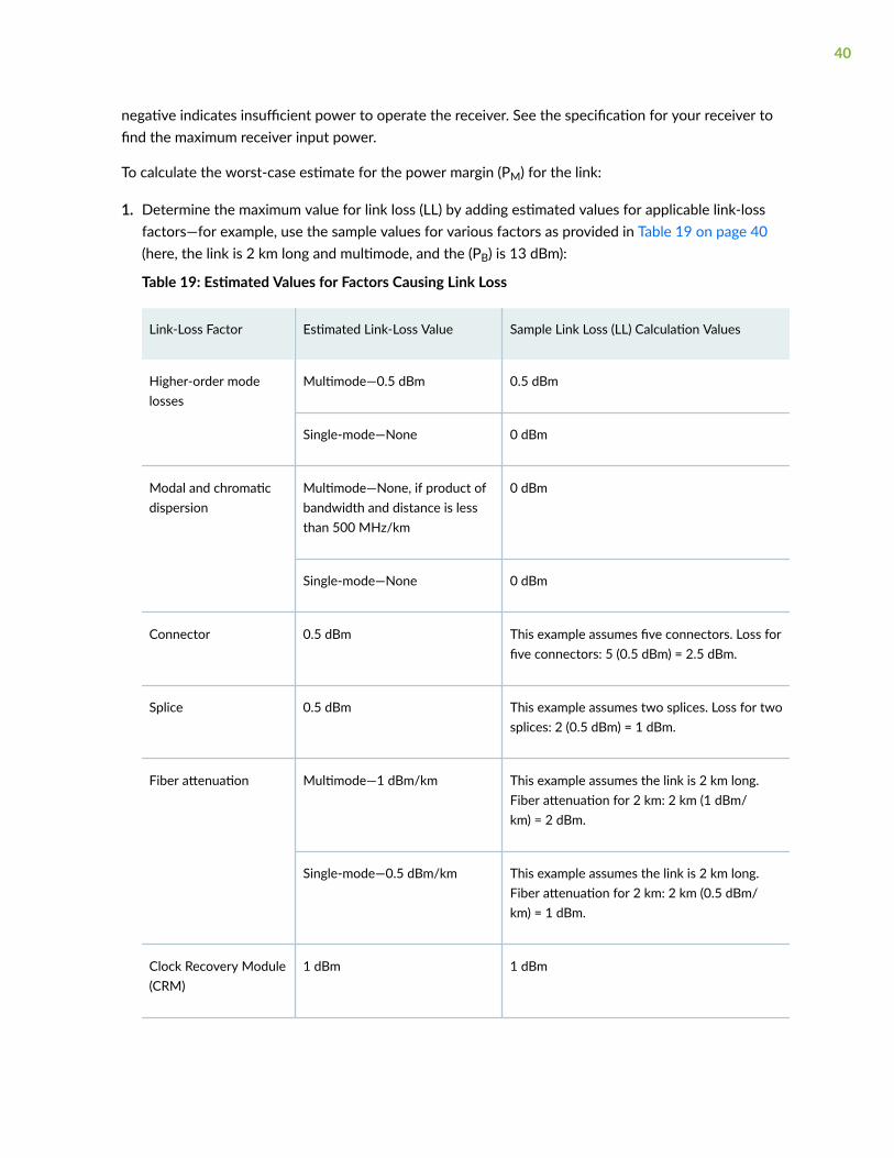
To calculate the worst-case estimate for the power margin (PM) for the link:
1. Determine the maximum value for link loss (LL) by adding estimated values for applicable link-lossfactors—for example, use the sample values for various factors as provided in Table 19 on page 40(here, the link is 2 km long and multimode, and the (PB) is 13 dBm):
Table 19: Estimated Values for Factors Causing Link Loss
Link-Loss Factor Estimated Link-Loss Value Sample Link Loss (LL) Calculation Values
Higher-order modelosses
Multimode—0.5 dBm 0.5 dBm
Single-mode—None 0 dBm
Modal and chromaticdispersion
Multimode—None, if product ofbandwidth and distance is lessthan 500 MHz/km
0 dBm
Single-mode—None 0 dBm
Connector 0.5 dBm This example assumes five connectors. Loss forfive connectors: 5 (0.5 dBm) = 2.5 dBm.
Splice 0.5 dBm This example assumes two splices. Loss for twosplices: 2 (0.5 dBm) = 1 dBm.
Fiber attenuation Multimode—1 dBm/km This example assumes the link is 2 km long.Fiber attenuation for 2 km: 2 km (1 dBm/km) = 2 dBm.
Single-mode—0.5 dBm/km This example assumes the link is 2 km long.Fiber attenuation for 2 km: 2 km (0.5 dBm/km) = 1 dBm.
Clock Recovery Module(CRM)
1 dBm 1 dBm
40

NOTE: For information about the actual amount of signal loss caused by equipment and otherfactors, see your vendor documentation for that equipment.
2. Calculate the (PM) by subtracting (LL) from (PB):
PB– LL = PM
13 dBm – 0.5 dBm [HOL] – 5 (0.5 dBm) – 2 (0.5 dBm) – 2 km (1.0 dBm/km) – 1 dB [CRM] = PM
13 dBm – 0.5 dBm – 2.5 dBm – 1 dBm – 2 dBm – 1 dBm = PM
PM = 6 dBm
The calculated power margin is greater than zero, indicating that the link has sufficient power fortransmission. Also, the power margin value does not exceed the maximum receiver input power.Refer to the specifications for your receiver to find the maximum receiver input power.
41

3CHAPTER
Initial Installation and Configuration
MX150 Installation Overview | 43
Unpacking and Mounting the MX150 | 43
Connecting the MX150 to Power | 53
Connecting the MX150 to the Network | 56
Performing the Initial Software Configuration for the MX150 | 60

MX150 Installation Overview
To install and connect an MX150:
1. Follow instructions in "Unpacking an MX150" on page 44.
2. Mount the MX150 by following instructions appropriate for your site:
• "Mounting an MX150 on a Desk or Other Level Surface" on page 47 (using the rubber feetprovided)
• "Mounting an MX150 on Two Posts in a Rack" on page 48 (using the mounting bracketsprovided)
• "Mounting an MX150 on Four Posts in a Rack or Cabinet" on page 50 (using the separatelyorderable four-post rack-mount kit)
3. Follow instructions in "Connecting Earth Ground to an MX150" on page 53.
4. Follow instructions in "Connecting AC Power to an MX150" on page 55.
5. Perform initial configuration of the device by following instructions in "Performing the InitialSoftware Configuration for the MX150" on page 60.
6. Set the device’s management options by following the appropriate instructions:
• "Connecting an MX150 to a Management Console" on page 57
Unpacking and Mounting the MX150
IN THIS SECTION
Unpacking an MX150 | 44
Parts Inventory (Packing List) for an MX150 | 44
Register Products—Mandatory to Validate SLAs | 45
Mounting an MX150 | 46
Mounting an MX150 on a Desk or Other Level Surface | 47
Mounting an MX150 on Two Posts in a Rack | 48
Mounting an MX150 on Four Posts in a Rack or Cabinet | 50
43

Unpacking an MX150
The MX150 is shipped in a cardboard carton, secured with foam packing material. The carton has anaccessory compartment and contains the quick start instructions.
CAUTION: The MX150 is maximally protected inside the shipping carton. Do notunpack the devices until you are ready to begin installation.
To unpack the device:
1. Open the carton.
2. Pull out the packing material holding the device in place.
3. Verify the parts received against the inventory on the label attached to the carton. See "PartsInventory (Packing List) for an MX150" on page 44.
4. Save the shipping carton and packing materials in case you need to move or ship the switch later.
Parts Inventory (Packing List) for an MX150
The MX150 is shipped in a cardboard carton, secured with foam packing material. The carton containsan accessory box.
The device shipment includes a packing list. Check the parts you receive in the device shipping cartonagainst the items on the packing list. The parts shipped depend on the configuration you order.
If any part on the packing list is missing, contact your customer service representative or contact Junipercustomer care from within the U.S. or Canada by telephone at 1-888-314-5822. For international-dial ordirect-dial options in countries without toll-free numbers, see https://www.juniper.net/support/requesting-support.html.
Table 20 on page 44 lists the parts and their quantities in the packing list.
Table 20: Packing List for an MX150
Component Quantity
Device 1
AC power cord appropriate for your geographical location 1
44
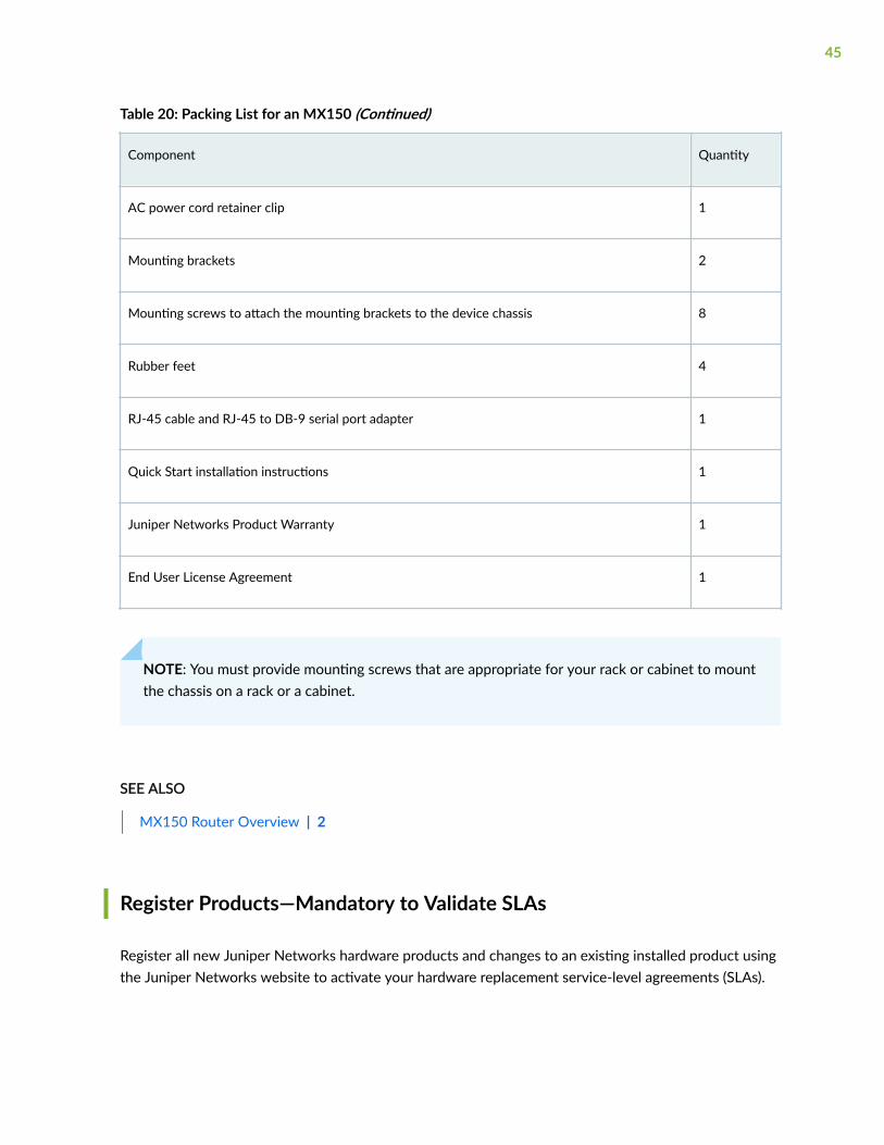
Table 20: Packing List for an MX150 (Continued)
Component Quantity
AC power cord retainer clip 1
Mounting brackets 2
Mounting screws to attach the mounting brackets to the device chassis 8
Rubber feet 4
RJ-45 cable and RJ-45 to DB-9 serial port adapter 1
Quick Start installation instructions 1
Juniper Networks Product Warranty 1
End User License Agreement 1
NOTE: You must provide mounting screws that are appropriate for your rack or cabinet to mountthe chassis on a rack or a cabinet.
SEE ALSO
MX150 Router Overview | 2
Register Products—Mandatory to Validate SLAs
Register all new Juniper Networks hardware products and changes to an existing installed product usingthe Juniper Networks website to activate your hardware replacement service-level agreements (SLAs).
45
CAUTION: Register product serial numbers on the Juniper Networks website andupdate the installation base data if there is any addition or change to the installationbase or if the installation base is moved. Juniper Networks will not be held accountablefor not meeting the hardware replacement service-level agreement for products that donot have registered serial numbers or accurate installation base data.
Register your product(s) at https://tools.juniper.net/svcreg/SRegSerialNum.jsp.Update your installation base at https://www.juniper.net/customers/csc/management/updateinstallbase.jsp.
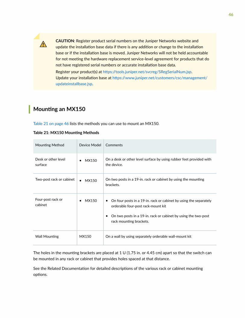
Mounting an MX150
Table 21 on page 46 lists the methods you can use to mount an MX150.
Table 21: MX150 Mounting Methods
Mounting Method Device Model Comments
Desk or other levelsurface
• MX150 On a desk or other level surface by using rubber feet provided withthe device.
Two-post rack or cabinet • MX150 On two posts in a 19-in. rack or cabinet by using the mountingbrackets.
Four-post rack orcabinet
• MX150 • On four posts in a 19-in. rack or cabinet by using the separatelyorderable four-post rack-mount kit
• On two posts in a 19-in. rack or cabinet by using the two-postrack mounting brackets.
Wall Mounting MX150 On a wall by using separately orderable wall-mount kit
The holes in the mounting brackets are placed at 1 U (1.75 in. or 4.45 cm) apart so that the switch canbe mounted in any rack or cabinet that provides holes spaced at that distance.
See the Related Documentation for detailed descriptions of the various rack or cabinet mountingoptions.
46

Mounting an MX150 on a Desk or Other Level Surface
Before mounting the MX150 on a desk or other level surface:
• Verify that the site meets the requirements described in "Site Preparation Checklist for MX150" onpage 18.
• Place the desk in its permanent location, allowing adequate clearance for airflow and maintenance,and secure it to the building structure.
• Read General Safety Guidelines and Warnings, with particular attention to "Chassis Lifting Guidelinesfor MX150" on page 93.
• Ensure that you have the four rubber feet to stabilize the chassis on the a desk or other level surface(provided in the accessory box in the router carton)
You can mount an MX150 on a desk or other level surface by using the four rubber feet that are shippedwith the router. The rubber feet stabilize the chassis.
To mount an MX150 on a desk or other level surface:
1. Remove the device from the shipping carton (see "Unpacking an MX150" on page 44).
2. Turn the chassis upside down on the desk or the level surface where you intend to mount the device.
3. Attach the rubber feet to the bottom of the chassis as shown in Figure 11 on page 47
4. Turn the chassis right side up on the desk or the level surface.
Figure 11: Attaching Rubber Feet to the MX150
SEE ALSO
Clearance Requirements for Airflow and Hardware Maintenance for an MX150 | 24
47
Mounting an MX150 on Two Posts in a Rack
Before mounting an MX150 on two posts in a rack:
• Place the rack in its permanent location, allowing adequate clearance for airflow and maintenance,and secure it to the building structure.
• Read General Safety Guidelines and Warnings.
• Remove the router from the shipping carton.
Ensure that you have the following parts and tools available:
• Phillips (+) screwdriver, number 2
• Two mounting brackets and eight mounting screws (provided in the accessory box shipped with therouter)
• Screws to secure the chassis to the rack (not provided)
You can mount an MX150 on two posts of a 19-in. rack (either a two-post or a four-post rack).
NOTE: If you need to mount the MX150 in a recessed position on either a two-post rack or afour-post rack, you can use the 2-in.-recess front brackets provided in the separately orderablefour-post rack-mount kit.
NOTE: One person must be available to lift the device while another secures the device to therack.
CAUTION: If you are mounting multiple devices on a rack, mount a device in thebottom of the rack first and proceed to mount the rest of the devices from bottom totop.
To mount the MX150 on two posts in a rack:
1. Place the MX150 on a flat, stable surface.
48
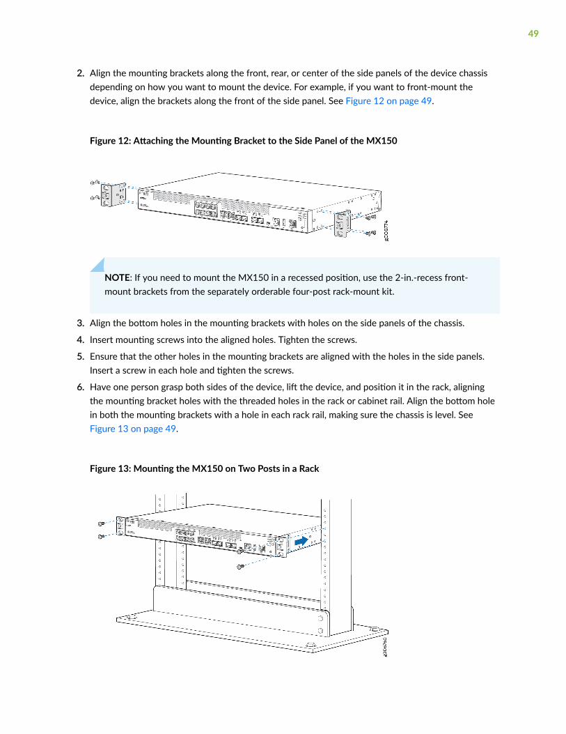
2. Align the mounting brackets along the front, rear, or center of the side panels of the device chassisdepending on how you want to mount the device. For example, if you want to front-mount thedevice, align the brackets along the front of the side panel. See Figure 12 on page 49.
Figure 12: Attaching the Mounting Bracket to the Side Panel of the MX150
NOTE: If you need to mount the MX150 in a recessed position, use the 2-in.-recess front-mount brackets from the separately orderable four-post rack-mount kit.
3. Align the bottom holes in the mounting brackets with holes on the side panels of the chassis.
4. Insert mounting screws into the aligned holes. Tighten the screws.
5. Ensure that the other holes in the mounting brackets are aligned with the holes in the side panels.Insert a screw in each hole and tighten the screws.
6. Have one person grasp both sides of the device, lift the device, and position it in the rack, aligningthe mounting bracket holes with the threaded holes in the rack or cabinet rail. Align the bottom holein both the mounting brackets with a hole in each rack rail, making sure the chassis is level. SeeFigure 13 on page 49.
Figure 13: Mounting the MX150 on Two Posts in a Rack
49

7. Have a second person secure the device to the rack by using the appropriate screws. Tighten thescrews.
8. Ensure that the device chassis is level by verifying that all screws on one side of the rack are alignedwith the screws on the other side.
SEE ALSO
Rack-Mounting and Cabinet-Mounting Warnings
Mounting an MX150 on Four Posts in a Rack or Cabinet
Before mounting the MX150 on four posts in a rack:
• Place the rack in its permanent location, allowing adequate clearance for airflow and maintenance,and secure it to the building structure.
• Read General Safety Guidelines and Warnings, with particular attention to "Chassis Lifting Guidelinesfor MX150" on page 93.
• Remove the MX150 from the shipping carton (see "Unpacking an MX150" on page 44).
• Have two persons available to mount the router. One person supports the device in a level position,and the second person secures the router to the rack.
Ensure that you have the following parts and tools available:
• Phillips (+) screwdriver, number 2
• 12 flat-head M4x6-mm Phillips mounting screws (provided with the four-post rack-mount kit)
• One pair of front-mounting brackets
• One pair of rear mounting blades
• Screws to secure the front-mounting brackets and the rear mounting blades to the rack (notprovided)
You can mount an MX150 on four posts of a 19-in. rack or cabinet by using the separately orderablefour-post rack-mount kit. (The remainder of this topic uses rack to mean rack or cabinet.).
You can mount the MX150 on two posts in either a two-post rack or a four-post rack by using themounting brackets provided with the router. See "Mounting an MX150 on Two Posts in a Rack" on page48.
50

NOTE: If you are mounting the MX150 on four posts, ensure that the rack is 21.5 in. (54.61 cms)through 31.5 in. (80.01 cms) deep if you will mount the device flush with the rack front and thatthe rack is 23.5 in. (59.69 cms) through 32.5 in. (82.55 cms) deep if you will mount the device2 in. recessed from the rack front, thus ensuring that the protective earthing terminal isaccessible through the opening in the rear mounting-blade.
CAUTION: If you are mounting multiple units on a rack, mount the heaviest unit at thebottom of the rack and mount the other units from the bottom of the rack to the top indecreasing order of the weight of the units.
To mount the MX150 on four posts in a rack:
1. Place the router on a flat, stable surface.
2. Align a front-mounting bracket (either flush with the front of the chassis or 2-in.-recessed from thefront of the chassis) along the side panel of the device chassis. Align the two holes in the front ofthe brackets with the two holes on the front of the side panel.
NOTE: Each side of the chassis has twelve holes for attaching the front-mounting bracketsto the device.
Six holes on the chassis side align with six holes in the front bracket when the front bracketis mounted flush with the chassis front or recessed 2 in. from the front of the chassis.
3. Insert M4x6-mm Phillips flat-head mounting screws into the two aligned holes and tighten thescrews. Ensure that the remaining two holes in the front bracket are aligned with the two holes inthe side panel. See Figure 14 on page 51.
Figure 14: Attaching the Front-Mounting Bracket to the Chassis
4. Insert M4x6-mm Phillips flat-head mounting screws into the remaining two holes in the frontbracket and tighten the screws.
51

5. Repeat Step 2 through Step 4 for attaching the front-mounting bracket to the other side of thechassis.
6. Have one person grasp both sides of the device, lift the device, and position it in the rack, aligningthe front bracket holes with the threaded holes in the front post of the rack. Align the bottom holein both the front-mounting brackets with a hole in each rack rail, making sure the chassis is level.See Figure 15 on page 52.
Figure 15: Mounting the MX150 on the Front Posts in a Rack
7. Have a second person secure the front of the device to the rack by using the appropriate screws foryour rack.
8. Slide the rear mounting blades into the front-mounting brackets.
9. Attach the rear mounting blades to the rear post by using the appropriate screws for your rack.Tighten the screws.
10. Ensure that the chassis is level by verifying that all the screws on the front of the rack are alignedwith the screws at the back of the rack.
SEE ALSO
Rack-Mounting and Cabinet-Mounting Warnings
52

Connecting the MX150 to Power
IN THIS SECTION
Connecting Earth Ground to an MX150 | 53
Connecting AC Power to an MX150 | 55
Connecting Earth Ground to an MX150
IN THIS SECTION
Parts and Tools Required for Connecting an MX150 to Earth Ground | 53
Connecting Earth Ground to an MX150 | 54
. Electromagnetic compatibility (EMC) and electrostatic discharge (ESD) requirements are met by thechassis. The AC power cord provides surge protection.
You must install the MX150 in a restricted-access location and ensure that the chassis is always properlygrounded. The MX150 has a two-hole protective grounding terminal provided on the chassis. See Figure16 on page 54. We recommend that you use this protective grounding terminal as the preferredmethod for grounding the chassis regardless of the power supply configuration. However, if additionalgrounding methods are available, you can also use those methods. For example, you can use thegrounding wire in the AC power cord or use the grounding terminal or lug on a DC power supply. Thistested system meets or exceeds all applicable EMC regulatory requirements with the two-holeprotective grounding terminal.
This topic describes:
Parts and Tools Required for Connecting an MX150 to Earth Ground
Table 22 on page 54 lists the earthing terminal location, grounding cable requirements, grounding lugspecifications, screws and washers required, and the screwdriver needed for connecting a device to
53

earth ground. Before you begin connecting a switch to earth ground, ensure you have the parts andtools required for your device.
Table 22: Parts and Tools Required for Connecting an MX150 to Earth Ground
Device EarthingTerminalLocation
Grounding CableRequirements
Grounding LugSpecifications
Screws andWashers
Screwdriver
AdditionalInformation
MX150
Rearpanel ofchassis
14 AWG (2 mm²),minimum 90°Cwire, or aspermitted by thelocal code
PanduitLCC10-14BWLor equivalent—not provided
• Two 10-32x .25 in.screws with#10 split-lock washer—not provided
• Two #10 flatwashers—not provided
Phillips (+) number 2
Connecting Earth Ground to an MX150
To connect earth ground to the MX150:
1. Connect one end of the grounding cable to a proper earth ground, such as the rack in which therouter is mounted.
2. Place the grounding lug attached to the grounding cable over the protective earthing terminal. SeeFigure 16 on page 54.
Figure 16: Connecting a Grounding Cable to an MX150
54
3. Secure the grounding lug to the protective earthing terminal with the washers and screws.
4. Dress the grounding cable and ensure that it does not touch or block access to other devicecomponents.
WARNING: Ensure that the cable does not drape where people could trip over it.
Connecting AC Power to an MX150
Ensure that you have the following parts and tools available:
• A power cord appropriate for your geographical location
• A power cord retainer clip
CAUTION: An MX150 gets additional grounding when you plug the power supply inthe device into a grounded AC power outlet by using the AC power cord appropriate foryour geographical location (see "AC Power Cord Specifications for an MX150" on page14).
The power supply in an MX150 is located on the rear panel.
To connect AC power to the device:
1. Squeeze the two sides of the power cord retainer clip and insert the L-shaped ends of the wire clipinto the holes in the bracket on each side of the AC power cord inlet on the rear panel.
The power cord retainer clip extends out of the chassis by 3 in. (7.62 cms).
2. Locate the power cord or cords shipped with the device; the cords have plugs appropriate for yourgeographical location. See "AC Power Cord Specifications for an MX150" on page 14.
WARNING: Ensure that the power cord does not drape where people can trip on it orblock access to switch components.
3. Insert the coupler end of the power cord into the AC power cord inlet on the rear panel.
4. Push the power cord into the slot in the adjustment nut of the power cord retainer clip. Turn the nutuntil it is tight against the base of the coupler and the slot in the nut is turned 90° from the top of thedevice.
5. If the AC power source outlet has a power switch, set it to the off (0) position.
55
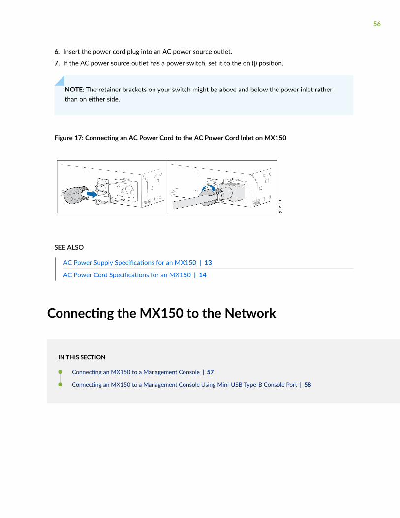
6. Insert the power cord plug into an AC power source outlet.
7. If the AC power source outlet has a power switch, set it to the on (|) position.
NOTE: The retainer brackets on your switch might be above and below the power inlet ratherthan on either side.
Figure 17: Connecting an AC Power Cord to the AC Power Cord Inlet on MX150
SEE ALSO
AC Power Supply Specifications for an MX150 | 13
AC Power Cord Specifications for an MX150 | 14
Connecting the MX150 to the Network
IN THIS SECTION
Connecting an MX150 to a Management Console | 57
Connecting an MX150 to a Management Console Using Mini-USB Type-B Console Port | 58
56

Connecting an MX150 to a Management Console
Ensure that you have an RJ-45 to DB-9 rollover cable available. An RJ-45 cable with an RJ-45 to DB-9adapter is provided with the device.
NOTE: If your laptop or PC does not have a DB-9 plug connector pin and you want to connectyour laptop or PC directly to the MX150, use a combination of the RJ-45 cable and RJ-45 toDB-9 adapter supplied with the device and a USB to DB-9 plug adapter. You must provide theUSB to DB-9 plug adapter.
MX150 has a console port with an RJ-45 connector. Use the console port to connect the device to amanagement console or to a console server.
To connect the MX150 to a management console (see Figure 18 on page 58 and Figure 19 on page58):
1. Connect one end of the Ethernet cable to the console port (labeled CON).
57

2. Connect the other end of the Ethernet cable into the console server (see Figure 18 on page 58) ormanagement console (see Figure 19 on page 58).
Figure 18: Connecting the MX150 to a Management Console Through a Console Server
Figure 19: Connecting the MX150 Directly to a Management Console
SEE ALSO
Console Port Connector Pinouts for MX150 | 29
Connecting an MX150 to a Management Console Using Mini-USB Type-BConsole Port
Before you begin connecting an MX150 by using the Mini-USB Type-B console port:
• Ensure that the USB to Serial driver is installed on the host machine. You can download the driverfrom https://webdownload.juniper.net/swdl/dl/secure/site/1/record/5029.html
• Ensure that the hyper terminal properties of the console server or laptop are set as follows:
58

• Baud rate—9600
• Flow control—None
• Data—8
• Parity—None
• Stop bits—1
• DCD state—Disregard
Ensure that you have the following parts and tools available:
• 1 mini-USB cable with Standard-A and Mini-USB Type- B (5-pin) connectors (not provided).
You can configure and manage the MX150 by using the RJ-45 console port or the Mini-USB Type-Bconsole port. However, the console input will be active only on one port at a time—only one port will beset active at a time.
By default, the RJ-45 port is set as an active console port and the Mini-USB Type-B port is the passiveconsole port. For information about configuring the console port type, see Configuring the Console PortType (CLI Procedure).
If your laptop or PC does not have a DB-9 plug connector pin or RJ-45 connector pin, you can connectyour laptop or PC directly to an MX150 device by using a mini-USB cable that has a Standard-A USBconnector on one end and a Mini-USB Type-B (5 pin) connector on the other end.
This section describes the process of connecting an MX150 to the management console by using theMini-USB Type-B console port.
For information about configuring and managing an MX150 by using the RJ-45 console port, see"Connecting an MX150 to a Management Console" on page 57.
To connect the MX150 to the console by using Mini-USB Type-B console port:
1. Connect the Standard-A connector of the mini-USB cable to the host machine (PC or Laptop).
2. Connect the Mini-USB Type-B (5-pin) connector of the mini-USB cable to the Mini-USB Type-Bconsole port (labeled CON) on the MX150.
3. Set the Mini-USB Type-B console port as the active console port by using the command port-type. Forinformation about configuring the console port type, see Configuring the Console Port Type (CLIProcedure).
4. Reboot the MX150.
After the connection is established, the Mini-USB Type-B becomes the active console port. The hostmachine connected to the Mini-USB Type-B console port displays log messages and lets you controlMX150 functionality through it.
59

SEE ALSO
Console Port Connector Pinouts for MX150 | 29
Performing the Initial Software Configuration for theMX150
Before you begin connecting and configuring an MX150, set the following parameter values on theconsole server or PC:
• Baud Rate—9600
• Flow Control—None
• Data—8
• Parity—None
• Stop Bits—1
• DCD State—Disregard
You must perform the initial configuration of the MX150 through the console port using the command-line interface (CLI).
To connect and configure the device from the console:
1. Connect the console port to a laptop or PC by using the supplied RJ-45 cable and RJ-45 to DB-9adapter. The console (CON) port is located on the management panel of the device.
2. Start the CLI.
root@host% cli
3. Enter configuration mode.
root@host> configure
4. Add a password to the root administration user account.
[edit]root@host# set system root-authentication plain-text-password
60
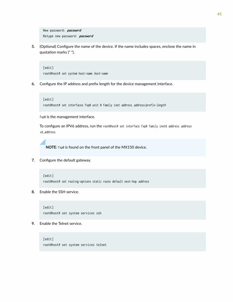
New password: passwordRetype new password: password
5. (Optional) Configure the name of the device. If the name includes spaces, enclose the name inquotation marks (“ ”).
[edit]root@host# set system host-name host-name
6. Configure the IP address and prefix length for the device management interface.
[edit]root@host# set interfaces fxp0 unit 0 family inet address address/prefix-length
fxp0 is the management interface.
To configure an IPV6 address, run the root@host# set interface fxp0 family inet6 address addressv6_address.
NOTE: fxp0 is found on the front panel of the MX150 device.
7. Configure the default gateway.
[edit]root@host# set routing-options static route default next-hop address
8. Enable the SSH service.
[edit] root@host# set system services ssh
9. Enable the Telnet service.
[edit] root@host# set system services telnet
61

10. Commit the configuration to activate it on the device.
[edit] root@host# commit
RELATED DOCUMENTATION
MX150 Installation Overview | 43
62
4CHAPTER
Maintaining Components
Maintaining MX150 Transceivers and Fiber-Optic Cables | 64
Removing the MX150 | 71
Maintaining MX150 Transceivers and Fiber-OpticCables
IN THIS SECTION
Removing a Transceiver from an MX150 | 64
Installing a Transceiver in an MX150 | 66
Maintaining Fiber-Optic Cables in an MX150 | 68
Connecting a Fiber-Optic Cable to an MX150 | 68
Disconnecting a Fiber-Optic Cable from an MX150 | 70
Removing a Transceiver from an MX150
Before you begin removing a transceiver from the MX150, ensure that you have taken the necessaryprecautions for safe handling of lasers (see "Laser and LED Safety Guidelines and Warnings for theMX150" on page 99).
Ensure that you have the following parts and tools available:
• Electrostatic bag or an antistatic mat
• Rubber safety caps to cover the transceiver and fiber-optic cable connector
• Dust cover to cover the port
The transceivers for the MX150 are hot-removable and hot-insertable field-replaceable units (FRUs). Youcan remove and replace them without powering off the device or disrupting device functions.
To remove a transceiver from the MX150:
1. Place the antistatic bag or antistatic mat on a flat, stable surface.
2. Label the cable connected to the transceiver so that you can reconnect it correctly.
64
LASER WARNING: Do not look directly into a fiber-optic transceiver or into the ends offiber-optic cables. Fiber-optic transceivers and fiber-optic cables connected to transceiversemit laser light that can damage your eyes.
LASER WARNING: Do not leave a fiber-optic transceiver uncovered except when insertingor removing a cable. The rubber safety cap keeps the port clean and prevents accidentalexposure to laser light.
CAUTION: Do not bend fiber-optic cables beyond their minimum bend radius. Bendingthe cables beyond their minimum bend radius can damage the cables and causeproblems that are difficult to diagnose.
3. Remove the cable connected to the transceiver (see "Disconnecting a Fiber-Optic Cable from anMX150" on page 70). Cover the transceiver and the end of each fiber-optic cable connector with arubber safety cap immediately after disconnecting the fiber-optic cables.
4. Using your fingers, pull the ejector lever away from the transceiver to unlock the transceiver.
CAUTION: Before removing the transceiver, make sure you open the ejector levercompletely until you hear it click. Doing this prevents damage to the transceiver.
5. Grasp the transceiver ejector lever and gently slide the transceiver approximately 0.5 in. (1.3 cm)straight out of the port (see Figure 20 on page 66).
CAUTION: To avoid electrostatic discharge (ESD) damage to the transceiver, do nottouch the connector pins at the end of the transceiver.
6. Using your fingers, grasp the body of the transceiver and pull it straight out of the port.
7. Place the transceiver in the electrostatic bag or on the antistatic mat placed on a flat, stable surface.
65

8. Place the dust cover over the empty port.
Figure 20: Removing a Transceiver from an MX150
Installing a Transceiver in an MX150
Before you begin installing a transceiver in an MX150, ensure that you have taken the necessaryprecautions for safe handling of lasers (see "Laser and LED Safety Guidelines and Warnings for theMX150" on page 99).
Ensure that you have a rubber safety cap available to cover the transceiver.
The transceivers for the MX150 are hot-removable and hot-insertable field-replaceable units (FRUs). Youcan remove and replace them without powering off the device or disrupting device functions.
To install a transceiver in an MX150 :
CAUTION: To avoid electrostatic discharge (ESD) damage to the transceiver, do nottouch the connector pins at the end of the transceiver.
1. Remove the transceiver from its bag.
2. Check to see whether the transceiver is covered by a rubber safety cap. If it is not, cover thetransceiver with a rubber safety cap.
66
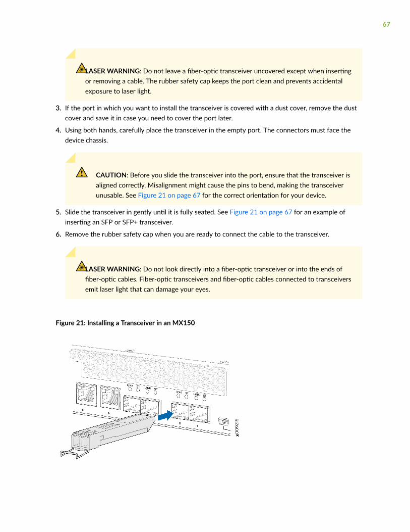
LASER WARNING: Do not leave a fiber-optic transceiver uncovered except when insertingor removing a cable. The rubber safety cap keeps the port clean and prevents accidentalexposure to laser light.
3. If the port in which you want to install the transceiver is covered with a dust cover, remove the dustcover and save it in case you need to cover the port later.
4. Using both hands, carefully place the transceiver in the empty port. The connectors must face thedevice chassis.
CAUTION: Before you slide the transceiver into the port, ensure that the transceiver isaligned correctly. Misalignment might cause the pins to bend, making the transceiverunusable. See Figure 21 on page 67 for the correct orientation for your device.
5. Slide the transceiver in gently until it is fully seated. See Figure 21 on page 67 for an example ofinserting an SFP or SFP+ transceiver.
6. Remove the rubber safety cap when you are ready to connect the cable to the transceiver.
LASER WARNING: Do not look directly into a fiber-optic transceiver or into the ends offiber-optic cables. Fiber-optic transceivers and fiber-optic cables connected to transceiversemit laser light that can damage your eyes.
Figure 21: Installing a Transceiver in an MX150
67

Maintaining Fiber-Optic Cables in an MX150
To maintain fiber-optic cables in MX150:
• When you unplug a fiber-optic cable from a transceiver, place rubber safety caps over the transceiverand on the end of the cable.
• Anchor fiber-optic cable to avoid stress on the connectors. When attaching a fiber-optic cable to atransceiver, be sure to secure the fiber-optic cable so that it is not supporting its own weight as ithangs to the floor. Never let a fiber-optic cable hang free from the connector.
• Do not bend fiber-optic cables beyond their minimum bend radius. Bending the cables beyond theirminimum bend radius can damage the cables and cause problems that are difficult to diagnose.
• Frequent plugging and unplugging of fiber-optic cables in and out of optical instruments can damagethe instruments, which are expensive to repair. Attach a short fiber extension to the opticalequipment. Any wear and tear due to frequent plugging and unplugging is then absorbed by theshort fiber extension, which is easier and less expensive to replace than the instruments.
• Keep fiber-optic cable connections clean. Microdeposits of oil and dust in the canal of the transceiveror cable connector can cause loss of light, reduction in signal power, and possibly intermittentproblems with the optical connection.
To clean the transceiver canal, use an appropriate fiber-cleaning device such as RIFOCS Fiber OpticAdaptor Cleaning Wands (part number 946). Follow the directions in the cleaning kit you use.
After cleaning the transceiver, make sure that the connector tip of the fiber-optic cable is clean. Useonly an approved alcohol-free fiber-optic cable cleaning kit such as the Cletop-S® Fiber Cleaner.Follow the directions in the cleaning kit you use.
Connecting a Fiber-Optic Cable to an MX150
Before you connect a fiber-optic cable to an optical transceiver installed in an MX150, ensure that youhave taken the necessary precautions for safe handling of lasers (see "Laser and LED Safety Guidelinesand Warnings for the MX150" on page 99).
You can connect fiber-optic cables to the field-replaceable unit (FRU) optical transceivers installed inMX150 routers.
To connect a fiber-optic cable to an optical transceiver installed in an MX150:
68

LASER WARNING: Do not look directly into a fiber-optic transceiver or into the ends offiber-optic cables. Fiber-optic transceivers and fiber-optic cables connected to transceiversemit laser light that can damage your eyes.
LASER WARNING: Do not stare into the laser beam or view it directly with opticalinstruments even if the interface has been disabled.
1. If the fiber-optic cable connector is covered by a rubber safety cap, remove the cap. Save the cap.
2. If the optical transceiver is covered by a rubber safety cap, remove the cap. Save the cap.
3. Insert the cable connector into the optical transceiver (see Figure 22 on page 69).
4. Secure the cables so that they are not supporting their own weight. Place excess cable out of theway in a neatly coiled loop. Placing fasteners on a loop helps cables maintain their shape.
CAUTION: Do not bend fiber-optic cables beyond their minimum bend radius. Bendingthe cables beyond their minimum bend radius can damage the cables and causeproblems that are difficult to diagnose.
CAUTION: Do not let fiber-optic cables hang free from the connector. Do not allowfastened loops of cables to dangle, which stresses the cables at the fastening point.
Figure 22: Inserting a Fiber-Optic Cable into a Transceiver
69
Disconnecting a Fiber-Optic Cable from an MX150
Before you disconnect a fiber-optic cable from an optical transceiver installed in an MX150, ensure thatyou have taken the necessary precautions for safe handling of lasers (see "Laser and LED SafetyGuidelines and Warnings for the MX150" on page 99).
Ensure that you have the following parts and tools available:
• Rubber safety cap to cover the transceiver
• Rubber safety cap to cover the fiber-optic cable connector
To disconnect a fiber-optic cable from an optical transceiver installed in the MX150:
1. (Recommended) Disable the port in which the transceiver is installed by including the disablestatement at the [edit interfaces] hierarchy level for the specific interface.
LASER WARNING: Do not look directly into a fiber-optic transceiver or into the ends offiber-optic cables. Fiber-optic transceivers and fiber-optic cables connected to transceiversemit laser light that can damage your eyes.
LASER WARNING: Do not stare into the laser beam or view it directly with opticalinstruments even if the interface has been disabled.
2. Carefully unplug the fiber-optic cable connector from the transceiver.
3. Cover the transceiver with a rubber safety cap.
LASER WARNING: Do not leave a fiber-optic transceiver uncovered except when insertingor removing a cable. The rubber safety cap keeps the port clean and prevents accidentalexposure to laser light.
4. Cover the fiber-optic cable connector with the rubber safety cap.
70

Removing the MX150
IN THIS SECTION
Powering Off an MX150 | 71
Removing an MX150 from a Rack or Cabinet | 73
Powering Off an MX150
If you need to power off the MX150, follow the procedure in this topic.
Before you power off the device:
• Ensure that you understand how to prevent electrostatic discharge damage. See Prevention ofElectrostatic Discharge Damage.
• Ensure that you do not need to forward traffic through the device.
Ensure that you have the following parts and tools available to power off the device:
• An ESD grounding strap
• An external management device such as a PC
• A cable to connect the external management device to the console port (CON) or management port(MGMT) on the device
To power off the device:
1. Connect the management device (such as a PC) to the console (CON) port or the management(MGMT) port on the device:
• For connecting a management device to the console port, see "Connecting an MX150 to aManagement Console" on page 57.
2. From the PC connected to the device, issue the following operational mode CLI command:
user@host> request system halt
This command shuts down the device gracefully and preserves system state information. A messagedisplays on the console confirming that the operating system has halted.
71

You will see the following output (or something similar, depending on the hardware being shut down):
user@host> request system halt warning: This command will halt all the members.If planning to halt only one member use the member optionHalt the system ? [yes,no] (no) yes
*** FINAL System shutdown message from user@host *** System going down IMMEDIATELY Shutdown NOW![pid 14102]message sent
{master:0}user@host> Waiting (max 300 seconds) for system process `vnlru' to stop...doneWaiting (max 300 seconds) for system process `vnlru_mem' to stop...doneWaiting (max 300 seconds) for system process `bufdaemon' to stop...doneWaiting (max 300 seconds) for system process `syncer' to stop...Syncing disks, vnodes remaining...3 3 1 2 2 0 0 0 0 done
syncing disks... All buffers synced.Uptime: 38d18h0m6srecorded reboot as normal shutdown
The operating system has halted.Please press any key to reboot
CAUTION: The final output of any version of this command is the “The operatingsystem has halted. Please press any key to reboot” message. Wait at least 60 secondsafter first seeing this message before following the instructions in Step 3 and Step 4 topower off the device.
CAUTION: Ensure that you have halted your system safely before turning off thepower supply.
72

3. Attach the ESD grounding strap to your bare wrist and connect the strap to the ESD point on thechassis.
4. Set the power switch to off (0) position.
SEE ALSO
Connecting AC Power to an MX150 | 55
Removing an MX150 from a Rack or Cabinet
Before removing the MX150 from a rack:
Ensure that you have the following parts and tools available to remove the device:
• A Phillips (+) screwdriver, number 2 or number 3, depending on the size of your rack mountingscrews.
• A labeled bag to hold the removed screws.
If you need to relocate an installed MX150, use the procedure described in this topic. (The remainder ofthis topic uses rack to mean rack or cabinet.)
NOTE: When you remove multiple devices from a rack, remove the device at the top of the rackfirst and proceed to remove the rest of the devices from top to bottom.
CAUTION: At least two people must be available to lift a device chassis out of a rack—one person to unscrew the mounting screws from the brackets and the second personto hold the chassis.
• Ensure that the rack or cabinet is stable and secured to the building.
• Ensure that there is enough space to place the removed device in its new location and along the pathto the new location.
• Read General Safety Guidelines and Warnings, with particular attention to "Chassis Lifting Guidelinesfor MX150" on page 93.
• Ensure that the device has been safely powered off and that you have unplugged (disconnected) thepower cords.
73

• Ensure that you have disconnected any cables or wires attached to the device.
To remove an MX150 from a rack:
1. Use the appropriate Phillips (+) screwdriver to remove the mounting screws that attach the chassisfront-mounting brackets to the rack.
2. Place the removed screws in a labeled bag. You will need them when you reinstall the chassis.
3. Lift the chassis from the rack and carefully move the chassis to its new location.
SEE ALSO
General Safety Guidelines and Warnings
Chassis Lifting Guidelines for MX150 | 93
74
5CHAPTER
Troubleshooting Hardware
Understanding Alarm Types and Severity Levels on MX150 | 76
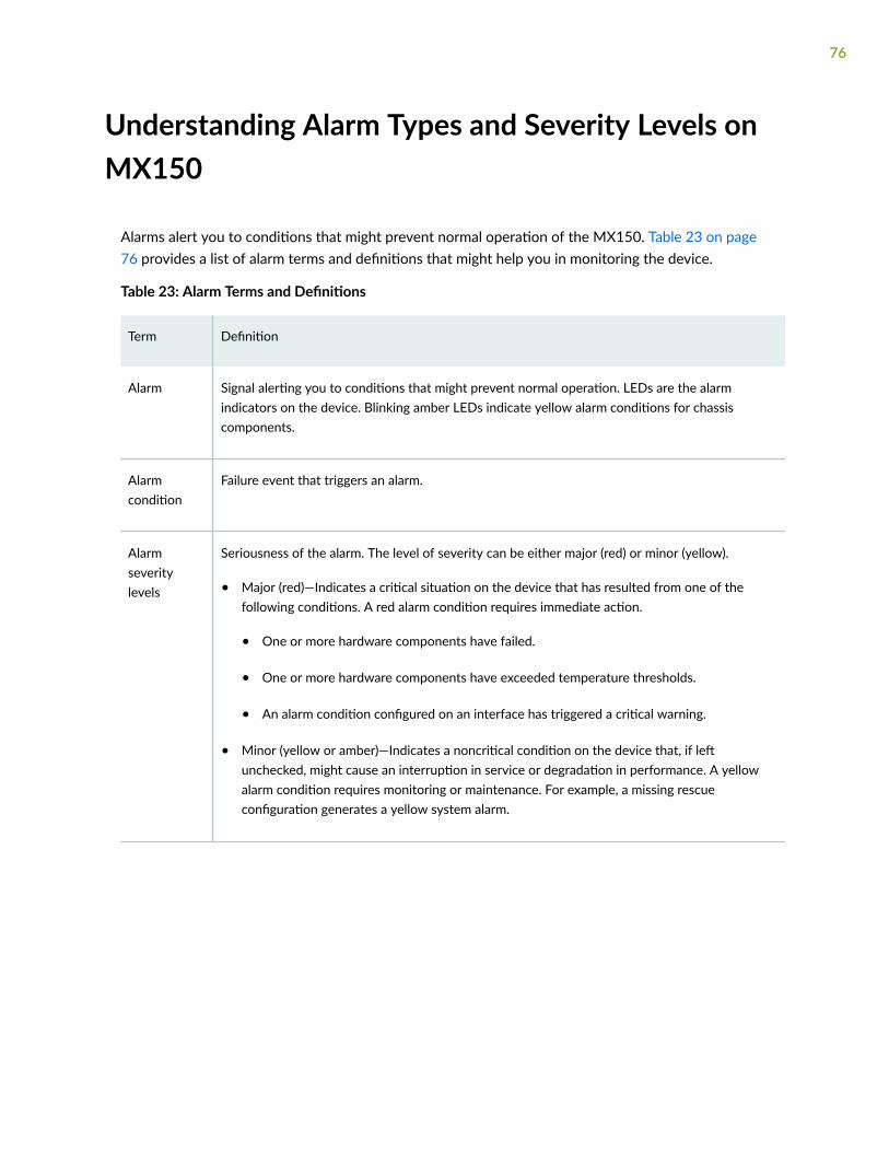
Understanding Alarm Types and Severity Levels onMX150
Alarms alert you to conditions that might prevent normal operation of the MX150. Table 23 on page76 provides a list of alarm terms and definitions that might help you in monitoring the device.
Table 23: Alarm Terms and Definitions
Term Definition
Alarm Signal alerting you to conditions that might prevent normal operation. LEDs are the alarmindicators on the device. Blinking amber LEDs indicate yellow alarm conditions for chassiscomponents.
Alarmcondition
Failure event that triggers an alarm.
Alarmseveritylevels
Seriousness of the alarm. The level of severity can be either major (red) or minor (yellow).
• Major (red)—Indicates a critical situation on the device that has resulted from one of thefollowing conditions. A red alarm condition requires immediate action.
• One or more hardware components have failed.
• One or more hardware components have exceeded temperature thresholds.
• An alarm condition configured on an interface has triggered a critical warning.
• Minor (yellow or amber)—Indicates a noncritical condition on the device that, if leftunchecked, might cause an interruption in service or degradation in performance. A yellowalarm condition requires monitoring or maintenance. For example, a missing rescueconfiguration generates a yellow system alarm.
76
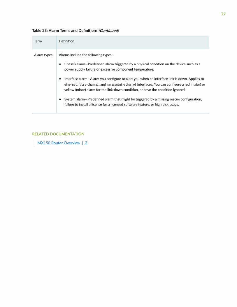
Table 23: Alarm Terms and Definitions (Continued)
Term Definition
Alarm types Alarms include the following types:
• Chassis alarm—Predefined alarm triggered by a physical condition on the device such as apower supply failure or excessive component temperature.
• Interface alarm—Alarm you configure to alert you when an interface link is down. Applies toethernet, fibre-channel, and management-ethernet interfaces. You can configure a red (major) oryellow (minor) alarm for the link-down condition, or have the condition ignored.
• System alarm—Predefined alarm that might be triggered by a missing rescue configuration,failure to install a license for a licensed software feature, or high disk usage.
RELATED DOCUMENTATION
MX150 Router Overview | 2
77

6CHAPTER
Contacting Customer Support andReturning the Chassis or Components
Contacting Customer Support and Returning the Chassis or Components | 79

Contacting Customer Support and Returning theChassis or Components
IN THIS SECTION
Contacting Customer Support to Obtain a Return Materials Authorization for an MX150 | 79
Locating the Serial Number on an MX150 | 80
Packing a MX150 Router or Component for Shipping | 82
Returning a MX150 Router or Component for Repair or Replacement | 83
Contacting Customer Support to Obtain a Return Materials Authorizationfor an MX150
If you are returning an MX150 router or component to Juniper Networks for repair or replacement,obtain a Return Materials Authorization (RMA) from the Juniper Networks Technical Assistance Center(JTAC).
After locating the serial number of the device or component you want to return, open a service requestwith Juniper Networks Technical Assistance Center (JTAC) on the Web or by telephone.
For instructions on locating the serial number of the device or component you want to return, see"Locating the Serial Number on an MX150" on page 80.
Before you request an RMA from JTAC, be prepared to provide the following information:
• Your existing service request number, if you have one
• Serial number of the component
• Your name, organization name, telephone number, fax number, and shipping address
• Details of the failure or problem
• Type of activity being performed on the device when the problem occurred
• Configuration data displayed by one or more show commands
You can contact JTAC 24 hours a day, seven days a week on the Web or by telephone:
79
• Service Request Manager: https://support.juniper.net/support
• Telephone: +1-888-314-JTAC (+1-888-314-5822), toll-free in the USA, Canada, and Mexico
NOTE: For international or direct-dial options in countries without toll-free numbers, see https://support.juniper.net/support/ .
If you are contacting JTAC by telephone, enter your 12-digit service request number followed by thepound (#) key for an existing case, or press the star (*) key to be routed to the next available supportengineer.
The support representative validates your request and issues an RMA number for return of thecomponent.
Locating the Serial Number on an MX150
IN THIS SECTION
Listing the Device and Components Details with the CLI | 80
Locating the Chassis Serial Number ID Label on an MX150 | 81
If you are returning a device to Juniper Networks for repair or replacement, you must locate the serialnumber of the device. You must provide the serial number to the Juniper Networks Technical AssistanceCenter (JTAC) when you contact them to obtain Return Materials Authorization (RMA).
If the device is operational and you can access the CLI, you can list serial numbers for the device with aCLI command.
NOTE: The MX150 does not have any field-replaceable unit. The power supply and fans arefixed.
Listing the Device and Components Details with the CLI
To list the device and device components and their serial numbers, enter the following CLI command:
The following output lists the device components and serial numbers for an MX150:
80
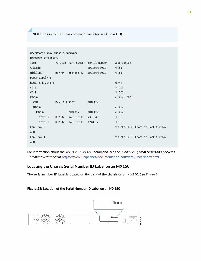
NOTE: Log in to the Junos command-line interface (Junos CLI).
user@host> show chassis hardwareHardware inventory:Item Version Part number Serial number DescriptionChassis DD2316AF0078 MX150Midplane REV 04 650-066113 DD2316AF0078 MX150Power Supply 0 Routing Engine 0 RE-MXCB 0 MX SCBCB 1 MX SCBFPC 0 Virtual FPC CPU Rev. 1.0 RIOT BUILTIN MIC 0 Virtual PIC 0 BUILTIN BUILTIN Virtual Xcvr 10 REV 02 740-013111 A331846 SFP-T Xcvr 11 REV 02 740-013111 C248517 SFP-TFan Tray 0 fan-ctrl-0 0, Front to Back Airflow - AFOFan Tray 1 fan-ctrl-0 1, Front to Back Airflow - AFO
For information about the show chassis hardware command, see the Junos OS System Basics and ServicesCommand Reference at https://www.juniper.net/documentation/software/junos/index.html .
Locating the Chassis Serial Number ID Label on an MX150
The serial number ID label is located on the back of the chassis on an MX150. See Figure 1.
Figure 23: Location of the Serial Number ID Label on an MX150
81

Packing a MX150 Router or Component for Shipping
IN THIS SECTION
Packing an MX150 for Shipping | 82
Packing MX150 Components for Shipping | 83
If you are returning a MX150 router or component to Juniper Networks for repair or replacement, packthe item as described in this topic.
Before you pack a MX150 router or component:
• Ensure that you have taken the necessary precautions to prevent electrostatic discharge (ESD)damage. See Prevention of Electrostatic Discharge Damage.
• Retrieve the original shipping carton and packing materials. Contact your JTAC representative if youdo not have these materials, to learn about approved packing materials. See "Contacting CustomerSupport to Obtain a Return Materials Authorization for an MX150" on page 79.
Ensure that you have the following parts and tools available:
• ESD grounding strap.
• Antistatic bag, one for each component.
• If you are returning the chassis, an appropriate screwdriver for the mounting screws used on yourrack or cabinet.
This topic describes:
Packing an MX150 for Shipping
To pack an MX150 for shipping:
1. Power off the MX150 and remove the power cables. See "Powering Off an MX150" on page 71.
2. Remove the cables that connect the device to all external devices.
3. Remove all field-replaceable units (FRUs) from the MX150.
4. Have one person support the weight of the device while another person unscrews and removes themounting screws.
5. Remove the device from the rack or cabinet (see "Chassis Lifting Guidelines for MX150" on page93) and place the device in an antistatic bag.
82

6. Place the device in the shipping carton.
7. Place the packing foam on top and around the device.
8. If you are returning accessories or FRUs with the device, pack them as instructed in "Packing aMX150 Router or Component for Shipping" on page 82.
9. Replace the accessory box on top of the packing foam.
10. Close the top of the cardboard shipping box and seal it with packing tape.
11. Write the RMA number on the exterior of the box to ensure proper tracking.
Packing MX150 Components for Shipping
CAUTION: Do not stack the MX150 components. Return individual components inseparate boxes if they do not fit together on one level in the shipping box.
To pack and ship MX150 components:
• Place individual FRUs in antistatic bags.
• Ensure that the components are adequately protected with packing materials and packed so that thepieces are prevented from moving around inside the carton.
• Close the top of the cardboard shipping box and seal it with packing tape.
• Write the RMA number on the exterior of the box to ensure proper tracking.
Returning a MX150 Router or Component for Repair or Replacement
If you need to return a MX150 router or component to Juniper Networks for repair or replacement,follow this procedure:
1. Determine the serial number of the device or component. For instructions, see "Locating the SerialNumber on an MX150" on page 80.
2. Obtain a Return Materials Authorization (RMA) number from the Juniper Technical Assistance Center(JTAC) as described in "Contacting Customer Support to Obtain a Return Materials Authorization foran MX150" on page 79.
NOTE: Do not return any device or component to Juniper Networks unless you have firstobtained an RMA number. Juniper Networks reserves the right to refuse shipments that donot have an RMA. Refused shipments are returned to the customer through collect freight.
83
3. Pack the MX150 router or component for shipping as described in "Packing a MX150 Router orComponent for Shipping" on page 82.
For more information about return and repair policies, see the customer support page at https://www.juniper.net/support/guidelines.html .
SEE ALSO
MX150 Router Overview | 2
84

7CHAPTER
Safety and Compliance Information
General Safety Guidelines and Warnings | 87
Definitions of Safety Warning Levels | 88
Qualified Personnel Warning | 90
Warning Statement for Norway and Sweden | 90
Fire Safety Requirements | 91
Installation Instructions Warning | 92
Chassis Lifting Guidelines for MX150 | 93
Restricted Access Warning | 93
Ramp Warning | 94
Rack-Mounting and Cabinet-Mounting Warnings | 95
Laser and LED Safety Guidelines and Warnings for the MX150 | 99
Radiation from Open Port Apertures Warning | 104
Maintenance and Operational Safety Guidelines and Warnings | 105
General Electrical Safety Guidelines and Warnings | 111
Action to Take After an Electrical Accident | 113
Prevention of Electrostatic Discharge Damage | 113
AC Power Electrical Safety Guidelines | 115
AC Power Disconnection Warning | 116
TN Power Warning | 117
Agency Approvals for MX150 | 118

Compliance Statements for EMC Requirements for MX150 | 119
General Safety Guidelines and Warnings
The following guidelines help ensure your safety and protect the device from damage. The list ofguidelines might not address all potentially hazardous situations in your working environment, so bealert and exercise good judgment at all times.
• Perform only the procedures explicitly described in the hardware documentation for this device.Make sure that only authorized service personnel perform other system services.
• Keep the area around the device clear and free from dust before, during, and after installation.
• Keep tools away from areas where people could trip over them while walking.
• Do not wear loose clothing or jewelry, such as rings, bracelets, or chains, which could become caughtin the device.
• Wear safety glasses if you are working under any conditions that could be hazardous to your eyes.
• Do not perform any actions that create a potential hazard to people or make the equipment unsafe.
• Never attempt to lift an object that is too heavy for one person to handle.
• Never install or manipulate wiring during electrical storms.
• Never install electrical jacks in wet locations unless the jacks are specifically designed for wetenvironments.
• Operate the device only when it is properly grounded.
• Follow the instructions in this guide to properly ground the device to earth.
• Replace fuses only with fuses of the same type and rating.
• Do not open or remove chassis covers or sheet-metal parts unless instructions are provided in thehardware documentation for this device. Such an action could cause severe electrical shock.
• Do not push or force any objects through any opening in the chassis frame. Such an action couldresult in electrical shock or fire.
• Avoid spilling liquid onto the chassis or onto any device component. Such an action could causeelectrical shock or damage the device.
• Avoid touching uninsulated electrical wires or terminals that have not been disconnected from theirpower source. Such an action could cause electrical shock.
87
• Some parts of the chassis, including AC and DC power supply surfaces, power supply unit handles,SFB card handles, and fan tray handles might become hot. The following label provides the warningof the hot surfaces on the chassis:
• Always ensure that all modules, power supplies, and cover panels are fully inserted and that theinstallation screws are fully tightened.
Definitions of Safety Warning Levels
The documentation uses the following levels of safety warnings (there are two Warning formats):
NOTE: You might find this information helpful in a particular situation, or you might overlook thisimportant information if it was not highlighted in a Note.
CAUTION: You need to observe the specified guidelines to prevent minor injury ordiscomfort to you or severe damage to the device.
Attention Veillez à respecter les consignes indiquées pour éviter toute incommodité oublessure légère, voire des dégâts graves pour l’appareil.
LASER WARNING: This symbol alerts you to the risk of personal injury from a laser.
Avertissement Ce symbole signale un risque de blessure provoquée par rayon laser.
WARNING: This symbol means danger. You are in a situation that could cause bodilyinjury. Before you work on any equipment, be aware of the hazards involved withelectrical circuitry and be familiar with standard practices for preventing accidents.
Waarschuwing Dit waarschuwingssymbool betekent gevaar. U verkeert in een situatiedie lichamelijk letsel kan veroorzaken. Voordat u aan enige apparatuur gaat werken,
88

dient u zich bewust te zijn van de bij elektrische schakelingen betrokken risico's en dientu op de hoogte te zijn van standaard maatregelen om ongelukken te voorkomen.
Varoitus Tämä varoitusmerkki merkitsee vaaraa. Olet tilanteessa, joka voi johtaaruumiinvammaan. Ennen kuin työskentelet minkään laitteiston parissa, ota selvääsähkökytkentöihin liittyvistä vaaroista ja tavanomaisista onnettomuuksienehkäisykeinoista.
Avertissement Ce symbole d'avertissement indique un danger. Vous vous trouvez dansune situation pouvant causer des blessures ou des dommages corporels. Avant detravailler sur un équipement, soyez conscient des dangers posés par les circuitsélectriques et familiarisez-vous avec les procédures couramment utilisées pour éviterles accidents.
Warnung Dieses Warnsymbol bedeutet Gefahr. Sie befinden sich in einer Situation, diezu einer Körperverletzung führen könnte. Bevor Sie mit der Arbeit an irgendeinemGerät beginnen, seien Sie sich der mit elektrischen Stromkreisen verbundenen Gefahrenund der Standardpraktiken zur Vermeidung von Unfällen bewußt.
Avvertenza Questo simbolo di avvertenza indica un pericolo. La situazione potrebbecausare infortuni alle persone. Prima di lavorare su qualsiasi apparecchiatura, occorreconoscere i pericoli relativi ai circuiti elettrici ed essere al corrente delle pratichestandard per la prevenzione di incidenti.
Advarsel Dette varselsymbolet betyr fare. Du befinner deg i en situasjon som kan føretil personskade. Før du utfører arbeid på utstyr, må du vare oppmerksom på defaremomentene som elektriske kretser innebærer, samt gjøre deg kjent med vanligpraksis når det gjelder å unngå ulykker.
Aviso Este símbolo de aviso indica perigo. Encontra-se numa situação que lhe poderácausar danos físicos. Antes de começar a trabalhar com qualquer equipamento,familiarize-se com os perigos relacionados com circuitos eléctricos, e com quaisquerpráticas comuns que possam prevenir possíveis acidentes.
¡Atención! Este símbolo de aviso significa peligro. Existe riesgo para su integridad física.Antes de manipular cualquier equipo, considerar los riesgos que entraña la corrienteeléctrica y familiarizarse con los procedimientos estándar de prevención de accidentes.
Varning! Denna varningssymbol signalerar fara. Du befinner dig i en situation som kanleda till personskada. Innan du utför arbete på någon utrustning måste du varamedveten om farorna med elkretsar och känna till vanligt förfarande för att förebyggaskador.
89

Qualified Personnel Warning
WARNING: Only trained and qualified personnel should install or replace the device.
Waarschuwing Installatie en reparaties mogen uitsluitend door getraind en bevoegdpersoneel uitgevoerd worden.
Varoitus Ainoastaan koulutettu ja pätevä henkilökunta saa asentaa tai vaihtaa tämänlaitteen.
Avertissement Tout installation ou remplacement de l'appareil doit être réalisé par dupersonnel qualifié et compétent.
Warnung Gerät nur von geschultem, qualifiziertem Personal installieren oderauswechseln lassen.
Avvertenza Solo personale addestrato e qualificato deve essere autorizzato ad installareo sostituire questo apparecchio.
Advarsel Kun kvalifisert personell med riktig opplæring bør montere eller bytte ut detteutstyret.
Aviso Este equipamento deverá ser instalado ou substituído apenas por pessoaldevidamente treinado e qualificado.
¡Atención! Estos equipos deben ser instalados y reemplazados exclusivamente porpersonal técnico adecuadamente preparado y capacitado.
Varning! Denna utrustning ska endast installeras och bytas ut av utbildad ochkvalificerad personal.
Warning Statement for Norway and Sweden
WARNING: The equipment must be connected to an earthed mains socket-outlet.
Advarsel Apparatet skal kobles til en jordet stikkontakt.
Varning! Apparaten skall anslutas till jordat nätuttag.
90
Fire Safety Requirements
IN THIS SECTION
Fire Suppression | 91
Fire Suppression Equipment | 91
In the event of a fire emergency, the safety of people is the primary concern. You should establishprocedures for protecting people in the event of a fire emergency, provide safety training, and properlyprovision fire-control equipment and fire extinguishers.
In addition, you should establish procedures to protect your equipment in the event of a fire emergency.Juniper Networks products should be installed in an environment suitable for electronic equipment. Werecommend that fire suppression equipment be available in the event of a fire in the vicinity of theequipment and that all local fire, safety, and electrical codes and ordinances be observed when youinstall and operate your equipment.
Fire Suppression
In the event of an electrical hazard or an electrical fire, you should first turn power off to the equipmentat the source. Then use a Type C fire extinguisher, which uses noncorrosive fire retardants, to extinguishthe fire.
Fire Suppression Equipment
Type C fire extinguishers, which use noncorrosive fire retardants such as carbon dioxide and Halotron™,are most effective for suppressing electrical fires. Type C fire extinguishers displace oxygen from thepoint of combustion to eliminate the fire. For extinguishing fire on or around equipment that draws airfrom the environment for cooling, you should use this type of inert oxygen displacement extinguisherinstead of an extinguisher that leaves residues on equipment.
Do not use multipurpose Type ABC chemical fire extinguishers (dry chemical fire extinguishers). Theprimary ingredient in these fire extinguishers is monoammonium phosphate, which is very sticky and
91
difficult to clean. In addition, in the presence of minute amounts of moisture, monoammoniumphosphate can become highly corrosive and corrodes most metals.
Any equipment in a room in which a chemical fire extinguisher has been discharged is subject topremature failure and unreliable operation. The equipment is considered to be irreparably damaged.
NOTE: To keep warranties effective, do not use a dry chemical fire extinguisher to control a fireat or near a Juniper Networks device. If a dry chemical fire extinguisher is used, the unit is nolonger eligible for coverage under a service agreement.
We recommend that you dispose of any irreparably damaged equipment in an environmentallyresponsible manner.
Installation Instructions Warning
WARNING: Read the installation instructions before you connect the device to a powersource.
Waarschuwing Raadpleeg de installatie-aanwijzingen voordat u het systeem met devoeding verbindt.
Varoitus Lue asennusohjeet ennen järjestelmän yhdistämistä virtalähteeseen.
Avertissement Avant de brancher le système sur la source d'alimentation, consulter lesdirectives d'installation.
Warnung Lesen Sie die Installationsanweisungen, bevor Sie das System an dieStromquelle anschließen.
Avvertenza Consultare le istruzioni di installazione prima di collegare il sistemaall'alimentatore.
Advarsel Les installasjonsinstruksjonene før systemet kobles til strømkilden.
Aviso Leia as instruções de instalação antes de ligar o sistema à sua fonte de energia.
¡Atención! Ver las instrucciones de instalación antes de conectar el sistema a la red dealimentación.
Varning! Läs installationsanvisningarna innan du kopplar systemet till dessströmförsörjningsenhet.
92

Chassis Lifting Guidelines for MX150
The weight of an MX150 is approximately 9.4 lb (4.3 kg). Observe the following guidelines for lifting andmoving an MX150:
• Before installing the MX150, verify that the intended site meets the specified power, environmental,and clearance requirements.
• Before lifting or moving the switch, disconnect all external cables.
RELATED DOCUMENTATION
General Safety Guidelines and Warnings
Installation Instructions Warning
Restricted Access Warning
WARNING: This unit is intended for installation in restricted access areas. A restrictedaccess area is an area to which access can be gained only by service personnel throughthe use of a special tool, lock and key, or other means of security, and which iscontrolled by the authority responsible for the location.
Waarschuwing Dit toestel is bedoeld voor installatie op plaatsen met beperkte toegang.Een plaats met beperkte toegang is een plaats waar toegang slechts doorservicepersoneel verkregen kan worden door middel van een speciaal instrument, eenslot en sleutel, of een ander veiligheidsmiddel, en welke beheerd wordt door deoverheidsinstantie die verantwoordelijk is voor de locatie.
Varoitus Tämä laite on tarkoitettu asennettavaksi paikkaan, johon pääsy on rajoitettua.Paikka, johon pääsy on rajoitettua, tarkoittaa paikkaa, johon vain huoltohenkilöstöpääsee jonkin erikoistyökalun, lukkoon sopivan avaimen tai jonkin muun turvalaitteenavulla ja joka on paikasta vastuussa olevien toimivaltaisten henkilöiden valvoma.
Avertissement Cet appareil est à installer dans des zones d'accès réservé. Ces dernièressont des zones auxquelles seul le personnel de service peut accéder en utilisant un outilspécial, un mécanisme de verrouillage et une clé, ou tout autre moyen de sécurité.
93

L'accès aux zones de sécurité est sous le contrôle de l'autorité responsable del'emplacement.
Warnung Diese Einheit ist zur Installation in Bereichen mit beschränktem Zutrittvorgesehen. Ein Bereich mit beschränktem Zutritt ist ein Bereich, zu dem nurWartungspersonal mit einem Spezialwerkzeugs, Schloß und Schlüssel oder andererSicherheitsvorkehrungen Zugang hat, und der von dem für die Anlage zuständigenGremium kontrolliert wird.
Avvertenza Questa unità deve essere installata in un'area ad accesso limitato. Un'areaad accesso limitato è un'area accessibile solo a personale di assistenza tramiteun'attrezzo speciale, lucchetto, o altri dispositivi di sicurezza, ed è controllatadall'autorità responsabile della zona.
Advarsel Denne enheten er laget for installasjon i områder med begrenset adgang. Etområde med begrenset adgang gir kun adgang til servicepersonale som bruker etspesielt verktøy, lås og nøkkel, eller en annen sikkerhetsanordning, og det kontrolleresav den autoriteten som er ansvarlig for området.
Aviso Esta unidade foi concebida para instalação em áreas de acesso restrito. Uma áreade acesso restrito é uma área à qual apenas tem acesso o pessoal de serviço autorizado,que possua uma ferramenta, chave e fechadura especial, ou qualquer outra forma desegurança. Esta área é controlada pela autoridade responsável pelo local.
¡Atención! Esta unidad ha sido diseñada para instalarse en áreas de acceso restringido.Área de acceso restringido significa un área a la que solamente tiene acceso el personalde servicio mediante la utilización de una herramienta especial, cerradura con llave, oalgún otro medio de seguridad, y que está bajo el control de la autoridad responsabledel local.
Varning! Denna enhet är avsedd för installation i områden med begränsat tillträde. Ettområde med begränsat tillträde får endast tillträdas av servicepersonal med ett specielltverktyg, lås och nyckel, eller annan säkerhetsanordning, och kontrolleras av denauktoritet som ansvarar för området.
Ramp Warning
WARNING: When installing the device, do not use a ramp inclined at more than 10degrees.
94

Waarschuwing Gebruik een oprijplaat niet onder een hoek van meer dan 10 graden.
Varoitus Älä käytä sellaista kaltevaa pintaa, jonka kaltevuus ylittää 10 astetta.
Avertissement Ne pas utiliser une rampe dont l'inclinaison est supérieure à 10 degrés.
Warnung Keine Rampen mit einer Neigung von mehr als 10 Grad verwenden.
Avvertenza Non usare una rampa con pendenza superiore a 10 gradi.
Advarsel Bruk aldri en rampe som heller mer enn 10 grader.
Aviso Não utilize uma rampa com uma inclinação superior a 10 graus.
¡Atención! No usar una rampa inclinada más de 10 grados.
Varning! Använd inte ramp med en lutning på mer än 10 grader.
Rack-Mounting and Cabinet-Mounting Warnings
Ensure that the rack or cabinet in which the device is installed is evenly and securely supported. Unevenmechanical loading could lead to a hazardous condition.
WARNING: To prevent bodily injury when mounting or servicing the device in a rack,take the following precautions to ensure that the system remains stable. The followingdirectives help maintain your safety:
• The device must be installed in a rack that is secured to the building structure.
• The device should be mounted at the bottom of the rack if it is the only unit in therack.
• When mounting the device on a partially filled rack, load the rack from the bottomto the top with the heaviest component at the bottom of the rack.
• If the rack is provided with stabilizing equipment, install the stabilizers beforemounting or servicing the device in the rack.
Waarschuwing Om lichamelijk letsel te voorkomen wanneer u dit toestel in een rekmonteert of het daar een servicebeurt geeft, moet u speciale voorzorgsmaatregelen
95

nemen om ervoor te zorgen dat het toestel stabiel blijft. De onderstaande richtlijnenworden verstrekt om uw veiligheid te verzekeren:
• De Juniper Networks switch moet in een stellage worden geïnstalleerd die aan eenbouwsel is verankerd.
• Dit toestel dient onderaan in het rek gemonteerd te worden als het toestel het enigein het rek is.
• Wanneer u dit toestel in een gedeeltelijk gevuld rek monteert, dient u het rek vanonderen naar boven te laden met het zwaarste onderdeel onderaan in het rek.
• Als het rek voorzien is van stabiliseringshulpmiddelen, dient u de stabilisatoren temonteren voordat u het toestel in het rek monteert of het daar een servicebeurtgeeft.
Varoitus Kun laite asetetaan telineeseen tai huolletaan sen ollessa telineessä, onnoudatettava erityisiä varotoimia järjestelmän vakavuuden säilyttämiseksi, jottavältytään loukkaantumiselta. Noudata seuraavia turvallisuusohjeita:
• Juniper Networks switch on asennettava telineeseen, joka on kiinnitettyrakennukseen.
• Jos telineessä ei ole muita laitteita, aseta laite telineen alaosaan.
• Jos laite asetetaan osaksi täytettyyn telineeseen, aloita kuormittaminen senalaosasta kaikkein raskaimmalla esineellä ja siirry sitten sen yläosaan.
• Jos telinettä varten on vakaimet, asenna ne ennen laitteen asettamista telineeseentai sen huoltamista siinä.
Avertissement Pour éviter toute blessure corporelle pendant les opérations de montageou de réparation de cette unité en casier, il convient de prendre des précautionsspéciales afin de maintenir la stabilité du système. Les directives ci-dessous sontdestinées à assurer la protection du personnel:
• Le rack sur lequel est monté le Juniper Networks switch doit être fixé à la structuredu bâtiment.
• Si cette unité constitue la seule unité montée en casier, elle doit être placée dans lebas.
• Si cette unité est montée dans un casier partiellement rempli, charger le casier debas en haut en plaçant l'élément le plus lourd dans le bas.
96

• Si le casier est équipé de dispositifs stabilisateurs, installer les stabilisateurs avant demonter ou de réparer l'unité en casier.
Warnung Zur Vermeidung von Körperverletzung beim Anbringen oder Warten dieserEinheit in einem Gestell müssen Sie besondere Vorkehrungen treffen, umsicherzustellen, daß das System stabil bleibt. Die folgenden Richtlinien sollen zurGewährleistung Ihrer Sicherheit dienen:
• Der Juniper Networks switch muß in einem Gestell installiert werden, das in derGebäudestruktur verankert ist.
• Wenn diese Einheit die einzige im Gestell ist, sollte sie unten im Gestell angebrachtwerden.
• Bei Anbringung dieser Einheit in einem zum Teil gefüllten Gestell ist das Gestell vonunten nach oben zu laden, wobei das schwerste Bauteil unten im Gestellanzubringen ist.
• Wird das Gestell mit Stabilisierungszubehör geliefert, sind zuerst die Stabilisatorenzu installieren, bevor Sie die Einheit im Gestell anbringen oder sie warten.
Avvertenza Per evitare infortuni fisici durante il montaggio o la manutenzione di questaunità in un supporto, occorre osservare speciali precauzioni per garantire che il sistemarimanga stabile. Le seguenti direttive vengono fornite per garantire la sicurezzapersonale:
• Il Juniper Networks switch deve essere installato in un telaio, il quale deve esserefissato alla struttura dell'edificio.
• Questa unità deve venire montata sul fondo del supporto, se si tratta dell'unica unitàda montare nel supporto.
• Quando questa unità viene montata in un supporto parzialmente pieno, caricare ilsupporto dal basso all'alto, con il componente più pesante sistemato sul fondo delsupporto.
• Se il supporto è dotato di dispositivi stabilizzanti, installare tali dispositivi prima dimontare o di procedere alla manutenzione dell'unità nel supporto.
Advarsel Unngå fysiske skader under montering eller reparasjonsarbeid på denneenheten når den befinner seg i et kabinett. Vær nøye med at systemet er stabilt.Følgende retningslinjer er gitt for å verne om sikkerheten:
97
• Juniper Networks switch må installeres i et stativ som er forankret tilbygningsstrukturen.
• Denne enheten bør monteres nederst i kabinettet hvis dette er den eneste enheten ikabinettet.
• Ved montering av denne enheten i et kabinett som er delvis fylt, skal kabinettetlastes fra bunnen og opp med den tyngste komponenten nederst i kabinettet.
• Hvis kabinettet er utstyrt med stabiliseringsutstyr, skal stabilisatorene installeres førmontering eller utføring av reparasjonsarbeid på enheten i kabinettet.
Aviso Para se prevenir contra danos corporais ao montar ou reparar esta unidade numaestante, deverá tomar precauções especiais para se certificar de que o sistema possuium suporte estável. As seguintes directrizes ajudá-lo-ão a efectuar o seu trabalho comsegurança:
• O Juniper Networks switch deverá ser instalado numa prateleira fixa à estrutura doedificio.
• Esta unidade deverá ser montada na parte inferior da estante, caso seja esta a únicaunidade a ser montada.
• Ao montar esta unidade numa estante parcialmente ocupada, coloque os itens maispesados na parte inferior da estante, arrumando-os de baixo para cima.
• Se a estante possuir um dispositivo de estabilização, instale-o antes de montar oureparar a unidade.
¡Atención! Para evitar lesiones durante el montaje de este equipo sobre un bastidor,oeriormente durante su mantenimiento, se debe poner mucho cuidado en que elsistema quede bien estable. Para garantizar su seguridad, proceda según las siguientesinstrucciones:
• El Juniper Networks switch debe instalarse en un bastidor fijado a la estructura deledificio.
• Colocar el equipo en la parte inferior del bastidor, cuando sea la única unidad en elmismo.
• Cuando este equipo se vaya a instalar en un bastidor parcialmente ocupado,comenzar la instalación desde la parte inferior hacia la superior colocando el equipomás pesado en la parte inferior.
98

• Si el bastidor dispone de dispositivos estabilizadores, instalar éstos antes de montaro proceder al mantenimiento del equipo instalado en el bastidor.
Varning! För att undvika kroppsskada när du installerar eller utför underhållsarbete pådenna enhet på en ställning måste du vidta särskilda försiktighetsåtgärder för attförsäkra dig om att systemet står stadigt. Följande riktlinjer ges för att trygga dinsäkerhet:
• Juniper Networks switch måste installeras i en ställning som är förankrad ibyggnadens struktur.
• Om denna enhet är den enda enheten på ställningen skall den installeras längst nedpå ställningen.
• Om denna enhet installeras på en delvis fylld ställning skall ställningen fyllas nedifrånoch upp, med de tyngsta enheterna längst ned på ställningen.
• Om ställningen är försedd med stabiliseringsdon skall dessa monteras fast innanenheten installeras eller underhålls på ställningen.
Laser and LED Safety Guidelines and Warnings forthe MX150
IN THIS SECTION
General Laser Safety Guidelines | 100
Class 1M Laser Product Warning | 100
Class 1M Laser Radiation Warning | 101
Class 1 Laser Product Warning | 101
Class 1 LED Product Warning | 101
Laser Beam Warning | 102
Unterminated Fiber-Optic Cable Warning | 103
The MX150 is equipped with laser transmitters:
99

• SFP and SFP+ transceivers are classified as Class 1 Laser Products (complies with 21 CFR 1040.10and 1040.11 except for deviations pursuant to Laser Notice 50, dated July 26, 2001) or Class 1 LEDProducts.
Observe the following guidelines and warnings:
General Laser Safety Guidelines
When working around ports that support optical transceivers, observe the following safety guidelines toprevent eye injury:
• Do not look into unterminated ports or at fibers that connect to unknown sources.
• Do not examine unterminated optical ports with optical instruments.
• Avoid direct exposure to the beam.
LASER WARNING: Unterminated optical connectors can emit invisible laser radiation. Thelens in the human eye focuses all the laser power on the retina, so focusing the eyedirectly on a laser source—even a low-power laser—could permanently damage the eye.
Class 1M Laser Product Warning
LASER WARNING: Class 1M laser product.
Waarschuwing Laserproducten van Klasse 1M (IEC).
Varoitus Luokan 1M (IEC) lasertuotteita.
Attention Produits laser catégorie 1M (IEC).
Warnung Laserprodukte der Klasse 1M (IEC).
Avvertenza Prodotti laser di Classe 1M (IEC).
Advarsel Klasse 1M (IEC) laserprodukter.
Aviso Produtos laser Classe 1M (IEC).
100
¡Atención! Productos láser de Clase 1M (IEC).
Varning! Laserprodukter av Klass 1M (IEC).
Class 1M Laser Radiation Warning
LASER WARNING: Class 1M laser radiation when open. Do not view directly with opticalinstruments.
Class 1 Laser Product Warning
LASER WARNING: Class 1 laser product.
Waarschuwing Klasse-1 laser produkt.
Varoitus Luokan 1 lasertuote.
Attention Produit laser de classe I.
Warnung Laserprodukt der Klasse 1.
Avvertenza Prodotto laser di Classe 1.
Advarsel Laserprodukt av klasse 1.
Aviso Produto laser de classe 1.
¡Atención! Producto láser Clase I.
Varning! Laserprodukt av klass 1.
Class 1 LED Product Warning
LASER WARNING: Class 1 LED product.
101

Waarschuwing Klasse 1 LED-product.
Varoitus Luokan 1 valodiodituote.
Attention Alarme de produit LED Class I.
Warnung Class 1 LED-Produktwarnung.
Avvertenza Avvertenza prodotto LED di Classe 1.
Advarsel LED-produkt i klasse 1.
Aviso Produto de classe 1 com LED.
¡Atención! Aviso sobre producto LED de Clase 1.
Varning! Lysdiodprodukt av klass 1.
Laser Beam Warning
LASER WARNING: Do not stare into the laser beam or view it directly with opticalinstruments.
Waarschuwing Niet in de straal staren of hem rechtstreeks bekijken met optischeinstrumenten.
Varoitus Älä katso säteeseen äläkä tarkastele sitä suoraan optisen laitteen avulla.
Attention Ne pas fixer le faisceau des yeux, ni l'observer directement à l'aide d'instrumentsoptiques.
Warnung Nicht direkt in den Strahl blicken und ihn nicht direkt mit optischen Gerätenprüfen.
Avvertenza Non fissare il raggio con gli occhi né usare strumenti ottici per osservarlodirettamente.
Advarsel Stirr eller se ikke direkte p strlen med optiske instrumenter.
Aviso Não olhe fixamente para o raio, nem olhe para ele directamente com instrumentosópticos.
¡Atención! No mirar fijamente el haz ni observarlo directamente con instrumentos ópticos.
102
Varning! Rikta inte blicken in mot strålen och titta inte direkt på den genom optiskainstrument.
Unterminated Fiber-Optic Cable Warning
WARNING: Invisible laser radiation might be emitted from the unterminated connectorof a fiber-optic cable. To avoid injury to your eye, do not view the fiber optics with amagnifying optical device, such as a loupe, within 100 mm.
Waarschuwing Er kunnen onzichtbare laserstralen worden uitgezonden vanuit hetuiteinde van de onafgebroken vezelkabel of connector. Niet in de straal kijken of dezerechtstreeks bekijken met optische instrumenten. Als u de laseruitvoer met bepaaldeoptische instrumenten bekijkt (zoals bijv. een oogloep, vergrootgras of microscoop)binnen een afstand van 100 mm kan dit gevaar voor uw ogen opleveren.
Varoitus Päättämättömän kuitukaapelin tai -liittimen päästä voi tulla näkymätöntälasersäteilyä. Älä tuijota sädettä tai katso sitä suoraan optisilla välineillä. Lasersäteenkatsominen tietyillä optisilla välineillä (esim. suurennuslasilla tai mikroskoopilla) 10 cm:npäästä tai sitä lähempää voi olla vaarallista silmille.
Attention Des émissions de radiations laser invisibles peuvent se produire à l'extrémitéd'un câble en fibre ou d'un raccord sans terminaison. Ne pas fixer du regard le rayon oul'observer directement avec des instruments optiques. L'observation du laser à l'aidecertains instruments optiques (loupes et microscopes) à une distance inférieure à 100mm peut poser des risques pour les yeux.
Warnung Eine unsichtbare Laserstrahlung kann vom Ende des nicht angeschlossenenGlasfaserkabels oder Steckers ausgestrahlt werden. Nicht in den Laserstrahl schauenoder diesen mit einem optischen Instrument direkt ansehen. Ein Betrachten desLaserstrahls mit bestimmten optischen Instrumenten, wie z.B. Augenlupen,Vergrößerungsgläsern und Mikroskopen innerhalb eines Abstands von 100 mm kann fürdas Auge gefährlich sein.
Avvertenza L'estremità del connettore o del cavo ottico senza terminazione puòemettere radiazioni laser invisibili. Non fissare il raggio od osservarlo in modo direttocon strumenti ottici. L'osservazione del fascio laser con determinati strumenti ottici(come lupette, lenti di ingrandimento o microscopi) entro una distanza di 100 mm puòprovocare danni agli occhi.
103

Advarsel Usynlig laserstråling kan emittere fra enden av den ikke-terminertefiberkabelen eller koblingen. Ikke se inn i strålen og se heller ikke direkte på strålen medoptiske instrumenter. Observering av laserutgang med visse optiske instrumenter (foreksempel øyelupe, forstørrelsesglass eller mikroskoper) innenfor en avstand på 100 mmkan være farlig for øynene.
Aviso Radiação laser invisível pode ser emitida pela ponta de um conector ou cabo defibra não terminado. Não olhe fixa ou diretamente para o feixe ou com instrumentosópticos. Visualizar a emissão do laser com certos instrumentos ópticos (por exemplo,lupas, lentes de aumento ou microscópios) a uma distância de 100 mm pode causarriscos à visão.
¡Atención! El extremo de un cable o conector de fibra sin terminación puede emitirradiación láser invisible. No se acerque al radio de acción ni lo mire directamente coninstrumentos ópticos. La exposición del ojo a una salida de láser con determinadosinstrumentos ópticos (por ejemplo, lupas y microscopios) a una distancia de 100 mmpuede comportar lesiones oculares.
Varning! Osynlig laserstrålning kan komma från änden på en oavslutad fiberkabel eller -anslutning. Titta inte rakt in i strålen eller direkt på den med optiska instrument. Att tittapå laserstrålen med vissa optiska instrument (t.ex. lupper, förstoringsglas och mikroskop)från ett avstånd på 100 mm kan skada ögonen.
RELATED DOCUMENTATION
General Safety Guidelines and Warnings
Radiation from Open Port Apertures Warning
Installation Instructions Warning
Grounded Equipment Warning
Radiation from Open Port Apertures Warning
LASER WARNING: Because invisible radiation might be emitted from the aperture of theport when no fiber cable is connected, avoid exposure to radiation and do not stare intoopen apertures.
104

Waarschuwing Aangezien onzichtbare straling vanuit de opening van de poort kan komenals er geen fiberkabel aangesloten is, dient blootstelling aan straling en het kijken in openopeningen vermeden te worden.
Varoitus Koska portin aukosta voi emittoitua näkymätöntä säteilyä, kun kuitukaapelia ei olekytkettynä, vältä säteilylle altistumista äläkä katso avoimiin aukkoihin.
Avertissement Des radiations invisibles à l'il nu pouvant traverser l'ouverture du portlorsqu'aucun câble en fibre optique n'y est connecté, il est recommandé de ne pas regarderfixement l'intérieur de ces ouvertures.
Warnung Aus der Port-Öffnung können unsichtbare Strahlen emittieren, wenn keinGlasfaserkabel angeschlossen ist. Vermeiden Sie es, sich den Strahlungen auszusetzen, undstarren Sie nicht in die Öffnungen!
Avvertenza Quando i cavi in fibra non sono inseriti, radiazioni invisibili possono essereemesse attraverso l'apertura della porta. Evitate di esporvi alle radiazioni e non guardatedirettamente nelle aperture.
Advarsel Unngå utsettelse for stråling, og stirr ikke inn i åpninger som er åpne, fordi usynligstråling kan emiteres fra portens åpning når det ikke er tilkoblet en fiberkabel.
Aviso Dada a possibilidade de emissão de radiação invisível através do orifício da via deacesso, quando esta não tiver nenhum cabo de fibra conectado, deverá evitar an EXposiçãoà radiação e não deverá olhar fixamente para orifícios que se encontrarem a descoberto.
¡Atención! Debido a que la apertura del puerto puede emitir radiación invisible cuando noexiste un cable de fibra conectado, evite mirar directamente a las aperturas para noexponerse a la radiación.
Varning! Osynlig strålning kan avges från en portöppning utan ansluten fiberkabel och dubör därför undvika att bli utsatt för strålning genom att inte stirra in i oskyddade öppningar.
Maintenance and Operational Safety Guidelines andWarnings
IN THIS SECTION
Battery Handling Warning | 106
105
Jewelry Removal Warning | 107
Lightning Activity Warning | 108
Operating Temperature Warning | 109
Product Disposal Warning | 110
While performing the maintenance activities for devices, observe the following guidelines and warnings:
Battery Handling Warning
WARNING: Replacing a battery incorrectly might result in an explosion. Replace abattery only with the same or equivalent type recommended by the manufacturer.Dispose of used batteries according to the manufacturer's instructions.
Waarschuwing Er is ontploffingsgevaar als de batterij verkeerd vervangen wordt.Vervang de batterij slechts met hetzelfde of een equivalent type dat door de fabrikantaanbevolen is. Gebruikte batterijen dienen overeenkomstig fabrieksvoorschriftenweggeworpen te worden.
Varoitus Räjähdyksen vaara, jos akku on vaihdettu väärään akkuun. Käytä vaihtamiseenainoastaan saman- tai vastaavantyyppistä akkua, joka on valmistajan suosittelema.Hävitä käytetyt akut valmistajan ohjeiden mukaan.
Avertissement Danger d'explosion si la pile n'est pas remplacée correctement. Ne laremplacer que par une pile de type semblable ou équivalent, recommandée par lefabricant. Jeter les piles usagées conformément aux instructions du fabricant.
Warnung Bei Einsetzen einer falschen Batterie besteht Explosionsgefahr. Ersetzen Siedie Batterie nur durch den gleichen oder vom Hersteller empfohlenen Batterietyp.Entsorgen Sie die benutzten Batterien nach den Anweisungen des Herstellers.
Advarsel Det kan være fare for eksplosjon hvis batteriet skiftes på feil måte. Skift kunmed samme eller tilsvarende type som er anbefalt av produsenten. Kasser bruktebatterier i henhold til produsentens instruksjoner.
Avvertenza Pericolo di esplosione se la batteria non è installata correttamente.Sostituire solo con una di tipo uguale o equivalente, consigliata dal produttore. Eliminarele batterie usate secondo le istruzioni del produttore.
106
Aviso Existe perigo de explosão se a bateria for substituída incorrectamente. Substituaa bateria por uma bateria igual ou de um tipo equivalente recomendado pelo fabricante.Destrua as baterias usadas conforme as instruções do fabricante.
¡Atención! Existe peligro de explosión si la batería se reemplaza de manera incorrecta.Reemplazar la baterían EXclusivamente con el mismo tipo o el equivalenterecomendado por el fabricante. Desechar las baterías gastadas según las instruccionesdel fabricante.
Varning! Explosionsfara vid felaktigt batteribyte. Ersätt endast batteriet med sammabatterityp som rekommenderas av tillverkaren eller motsvarande. Följ tillverkarensanvisningar vid kassering av använda batterier.
Jewelry Removal Warning
WARNING: Before working on equipment that is connected to power lines, removejewelry, including rings, necklaces, and watches. Metal objects heat up when connectedto power and ground and can cause serious burns or can be welded to the terminals.
Waarschuwing Alvorens aan apparatuur te werken die met elektrische leidingen isverbonden, sieraden (inclusief ringen, kettingen en horloges) verwijderen. Metalenvoorwerpen worden warm wanneer ze met stroom en aarde zijn verbonden, en kunnenernstige brandwonden veroorzaken of het metalen voorwerp aan de aansluitklemmenlassen.
Varoitus Ennen kuin työskentelet voimavirtajohtoihin kytkettyjen laitteiden parissa, otapois kaikki korut (sormukset, kaulakorut ja kellot mukaan lukien). Metalliesineetkuumenevat, kun ne ovat yhteydessä sähkövirran ja maan kanssa, ja ne voivat aiheuttaavakavia palovammoja tai hitsata metalliesineet kiinni liitäntänapoihin.
Avertissement Avant d'accéder à cet équipement connecté aux lignes électriques, ôtertout bijou (anneaux, colliers et montres compris). Lorsqu'ils sont branchés àl'alimentation et reliés à la terre, les objets métalliques chauffent, ce qui peut provoquerdes blessures graves ou souder l'objet métallique aux bornes.
Warnung Vor der Arbeit an Geräten, die an das Netz angeschlossen sind, jeglichenSchmuck (einschließlich Ringe, Ketten und Uhren) abnehmen. Metallgegenständeerhitzen sich, wenn sie an das Netz und die Erde angeschlossen werden, und könnenschwere Verbrennungen verursachen oder an die Anschlußklemmen angeschweißtwerden.
107
Avvertenza Prima di intervenire su apparecchiature collegate alle linee di alimentazione,togliersi qualsiasi monile (inclusi anelli, collane, braccialetti ed orologi). Gli oggettimetallici si riscaldano quando sono collegati tra punti di alimentazione e massa: possonocausare ustioni gravi oppure il metallo può saldarsi ai terminali.
Advarsel Fjern alle smykker (inkludert ringer, halskjeder og klokker) før du skal arbeidepå utstyr som er koblet til kraftledninger. Metallgjenstander som er koblet tilkraftledninger og jord blir svært varme og kan forårsake alvorlige brannskader ellersmelte fast til polene.
Aviso Antes de trabalhar em equipamento que esteja ligado a linhas de corrente, retiretodas as jóias que estiver a usar (incluindo anéis, fios e relógios). Os objectos metálicosaquecerão em contacto com a corrente e em contacto com a ligação à terra, podendocausar queimaduras graves ou ficarem soldados aos terminais.
¡Atención! Antes de operar sobre equipos conectados a líneas de alimentación, quitarselas joyas (incluidos anillos, collares y relojes). Los objetos de metal se calientan cuandose conectan a la alimentación y a tierra, lo que puede ocasionar quemaduras graves oque los objetos metálicos queden soldados a los bornes.
Varning! Tag av alla smycken (inklusive ringar, halsband och armbandsur) innan duarbetar på utrustning som är kopplad till kraftledningar. Metallobjekt hettas upp när dekopplas ihop med ström och jord och kan förorsaka allvarliga brännskador; metallobjektkan också sammansvetsas med kontakterna.
Lightning Activity Warning
WARNING: Do not work on the system or connect or disconnect cables during periodsof lightning activity.
Waarschuwing Tijdens onweer dat gepaard gaat met bliksem, dient u niet aan hetsysteem te werken of kabels aan te sluiten of te ontkoppelen.
Varoitus Älä työskentele järjestelmän parissa äläkä yhdistä tai irrota kaapeleitaukkosilmalla.
Avertissement Ne pas travailler sur le système ni brancher ou débrancher les câblespendant un orage.
108
Warnung Arbeiten Sie nicht am System und schließen Sie keine Kabel an bzw. trennenSie keine ab, wenn es gewittert.
Avvertenza Non lavorare sul sistema o collegare oppure scollegare i cavi durante untemporale con fulmini.
Advarsel Utfør aldri arbeid på systemet, eller koble kabler til eller fra systemet når dettordner eller lyner.
Aviso Não trabalhe no sistema ou ligue e desligue cabos durante períodos de mautempo (trovoada).
¡Atención! No operar el sistema ni conectar o desconectar cables durante el transcursode descargas eléctricas en la atmósfera.
Varning! Vid åska skall du aldrig utföra arbete på systemet eller ansluta eller koppla losskablar.
Operating Temperature Warning
WARNING: To prevent the device from overheating, do not operate it in an area thatexceeds the maximum recommended ambient temperature. To prevent airflowrestriction, allow at least 6 in. (15.2 cm) of clearance around the ventilation openings.
Waarschuwing Om te voorkomen dat welke switch van de Juniper Networks router danook oververhit raakt, dient u deze niet te bedienen op een plaats waar de maximaleaanbevolen omgevingstemperatuur van 40° C wordt overschreden. Om te voorkomendat de luchtstroom wordt beperkt, dient er minstens 15,2 cm speling rond de ventilatie-openingen te zijn.
Varoitus Ettei Juniper Networks switch-sarjan reititin ylikuumentuisi, sitä ei saa käyttäätilassa, jonka lämpötila ylittää korkeimman suositellun ympäristölämpötilan 40° C. Etteiilmanvaihto estyisi, tuuletusaukkojen ympärille on jätettävä ainakin 15,2 cm tilaa.
Avertissement Pour éviter toute surchauffe des routeurs de la gamme JuniperNetworks switch, ne l'utilisez pas dans une zone où la température ambiante estsupérieure à 40° C. Pour permettre un flot d'air constant, dégagez un espace d'au moins15,2 cm autour des ouvertures de ventilations.
Warnung Um einen Router der switch vor Überhitzung zu schützen, darf dieser nicht ineiner Gegend betrieben werden, in der die Umgebungstemperatur das empfohlene
109
Maximum von 40° C überschreitet. Um Lüftungsverschluß zu verhindern, achten Siedarauf, daß mindestens 15,2 cm lichter Raum um die Lüftungsöffnungen herum freibleibt.
Avvertenza Per evitare il surriscaldamento dei switch, non adoperateli in un locale cheecceda la temperatura ambientale massima di 40° C. Per evitare che la circolazionedell'aria sia impedita, lasciate uno spazio di almeno 15.2 cm di fronte alle aperture delleventole.
Advarsel Unngå overoppheting av eventuelle rutere i Juniper Networks switch Disseskal ikke brukes på steder der den anbefalte maksimale omgivelsestemperaturenoverstiger 40° C (104° F). Sørg for at klaringen rundt lufteåpningene er minst 15,2 cm(6 tommer) for å forhindre nedsatt luftsirkulasjon.
Aviso Para evitar o sobreaquecimento do encaminhador Juniper Networks switch, nãoutilize este equipamento numa área que exceda a temperatura máxima recomendada de40° C. Para evitar a restrição à circulação de ar, deixe pelo menos um espaço de 15,2 cmà volta das aberturas de ventilação.
¡Atención! Para impedir que un encaminador de la serie Juniper Networks switch serecaliente, no lo haga funcionar en un área en la que se supere la temperatura ambientemáxima recomendada de 40° C. Para impedir la restricción de la entrada de aire, deje unespacio mínimo de 15,2 cm alrededor de las aperturas para ventilación.
Varning! Förhindra att en Juniper Networks switch överhettas genom att inte användaden i ett område där den maximalt rekommenderade omgivningstemperaturen på 40° Cöverskrids. Förhindra att luftcirkulationen inskränks genom att se till att det finns frittutrymme på minst 15,2 cm omkring ventilationsöppningarna.
Product Disposal Warning
WARNING: Disposal of this device must be handled according to all national laws andregulations.
Waarschuwing Dit produkt dient volgens alle landelijke wetten en voorschriften teworden afgedankt.
Varoitus Tämän tuotteen lopullisesta hävittämisestä tulee huolehtia kaikkiavaltakunnallisia lakeja ja säännöksiä noudattaen.
110
Avertissement La mise au rebut définitive de ce produit doit être effectuéeconformément à toutes les lois et réglementations en vigueur.
Warnung Dieses Produkt muß den geltenden Gesetzen und Vorschriften entsprechendentsorgt werden.
Avvertenza L'eliminazione finale di questo prodotto deve essere eseguita osservando lenormative italiane vigenti in materia
Advarsel Endelig disponering av dette produktet må skje i henhold til nasjonale lover ogforskrifter.
Aviso A descartagem final deste produto deverá ser efectuada de acordo com osregulamentos e a legislação nacional.
¡Atención! El desecho final de este producto debe realizarse según todas las leyes yregulaciones nacionales
Varning! Slutlig kassering av denna produkt bör skötas i enlighet med landets alla lagaroch föreskrifter.
General Electrical Safety Guidelines and Warnings
WARNING: Certain ports on the device are designed for use as intrabuilding (within-the-building) interfaces only (Type 2 or Type 4 ports as described in GR-1089-CORE)and require isolation from the exposed outside plant (OSP) cabling. To comply withNEBS requirements and protect against lightning surges and commercial powerdisturbances, the intrabuilding ports must not be metallically connected to interfacesthat connect to the OSP or its wiring. The intrabuilding ports on the device are suitablefor connection to intrabuilding or unexposed wiring or cabling only. The addition ofprimary protectors is not sufficient protection for connecting these interfacesmetallically to OSP wiring.
Avertissement Certains ports de l’appareil sont destinés à un usage en intérieuruniquement (ports Type 2 ou Type 4 tels que décrits dans le document GR-1089-CORE)et doivent être isolés du câblage de l’installation extérieure exposée. Pour respecter lesexigences NEBS et assurer une protection contre la foudre et les perturbations detension secteur, les ports pour intérieur ne doivent pas être raccordés physiquementaux interfaces prévues pour la connexion à l’installation extérieure ou à son câblage. Les
111

ports pour intérieur de l’appareil sont réservés au raccordement de câbles pour intérieurou non exposés uniquement. L’ajout de protections ne constitue pas une précautionsuffisante pour raccorder physiquement ces interfaces au câblage de l’installationextérieure.
CAUTION: Before removing or installing components of a device, connect anelectrostatic discharge (ESD) grounding strap to an ESD point and wrap and fasten theother end of the strap around your bare wrist. Failure to use an ESD grounding strapcould result in damage to the device.
Attention Avant de retirer ou d’installer des composants d’un appareil, raccordez unbracelet antistatique à un point de décharge électrostatique et fixez le bracelet à votrepoignet nu. L’absence de port d’un bracelet antistatique pourrait provoquer des dégâtssur l’appareil.
• Install the device in compliance with the following local, national, and international electrical codes:
• United States—National Fire Protection Association (NFPA 70), United States National ElectricalCode.
• Other countries—International Electromechanical Commission (IEC) 60364, Part 1 through Part 7.
• Evaluated to the TN power system.
• Canada—Canadian Electrical Code, Part 1, CSA C22.1.
• Suitable for installation in Information Technology Rooms in accordance with Article 645 of theNational Electrical Code and NFPA 75.
Peut être installé dans des salles de matériel de traitement de l’information conformément àl’article 645 du National Electrical Code et à la NFPA 75.
• Locate the emergency power-off switch for the room in which you are working so that if an electricalaccident occurs, you can quickly turn off the power.
• Make sure that grounding surfaces are cleaned and brought to a bright finish before groundingconnections are made.
• Do not work alone if potentially hazardous conditions exist anywhere in your workspace.
• Never assume that power is disconnected from a circuit. Always check the circuit before starting towork.
• Carefully look for possible hazards in your work area, such as moist floors, ungrounded powerextension cords, and missing safety grounds.
112

• Operate the device within marked electrical ratings and product usage instructions.
• To ensure that the device and peripheral equipment function safely and correctly, use the cables andconnectors specified for the attached peripheral equipment, and make certain they are in goodcondition.
You can remove and replace many device components without powering off or disconnecting power tothe device, as detailed elsewhere in the hardware documentation for this device. Never installequipment that appears to be damaged.
Action to Take After an Electrical Accident
If an electrical accident results in an injury, take the following actions in this order:
1. Use caution. Be aware of potentially hazardous conditions that could cause further injury.
2. Disconnect power from the device.
3. If possible, send another person to get medical aid. Otherwise, assess the condition of the victim,then call for help.
Prevention of Electrostatic Discharge Damage
Device components that are shipped in antistatic bags are sensitive to damage from static electricity.Some components can be impaired by voltages as low as 30 V. You can easily generate potentiallydamaging static voltages whenever you handle plastic or foam packing material or if you movecomponents across plastic or carpets. Observe the following guidelines to minimize the potential forelectrostatic discharge (ESD) damage, which can cause intermittent or complete component failures:
• Always use an ESD wrist strap when you are handling components that are subject to ESD damage,and make sure that it is in direct contact with your skin.
If a grounding strap is not available, hold the component in its antistatic bag (see Figure 24 on page114) in one hand and touch the exposed, bare metal of the device with the other hand immediatelybefore inserting the component into the device.
113
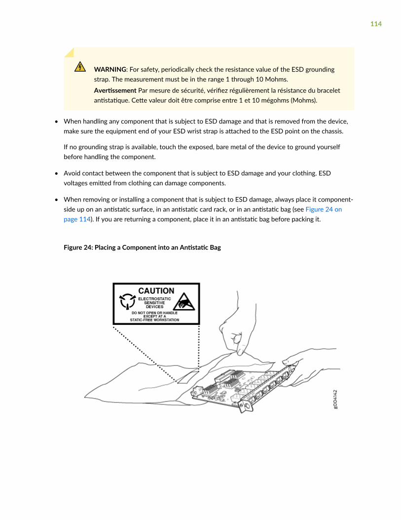
WARNING: For safety, periodically check the resistance value of the ESD groundingstrap. The measurement must be in the range 1 through 10 Mohms.
Avertissement Par mesure de sécurité, vérifiez régulièrement la résistance du braceletantistatique. Cette valeur doit être comprise entre 1 et 10 mégohms (Mohms).
• When handling any component that is subject to ESD damage and that is removed from the device,make sure the equipment end of your ESD wrist strap is attached to the ESD point on the chassis.
If no grounding strap is available, touch the exposed, bare metal of the device to ground yourselfbefore handling the component.
• Avoid contact between the component that is subject to ESD damage and your clothing. ESDvoltages emitted from clothing can damage components.
• When removing or installing a component that is subject to ESD damage, always place it component-side up on an antistatic surface, in an antistatic card rack, or in an antistatic bag (see Figure 24 onpage 114). If you are returning a component, place it in an antistatic bag before packing it.
Figure 24: Placing a Component into an Antistatic Bag
114

CAUTION: ANSI/TIA/EIA-568 cables such as Category 5e and Category 6 can getelectrostatically charged. To dissipate this charge, always ground the cables to a suitableand safe earth ground before connecting them to the system.
Attention Les câbles ANSI/TIA/EIA-568, par exemple Cat 5e et Cat 6, peuventemmagasiner des charges électrostatiques. Pour évacuer ces charges, reliez toujours lescâbles à une prise de terre adaptée avant de les raccorder au système.
AC Power Electrical Safety Guidelines
The following electrical safety guidelines apply to AC-powered devices:
• Note the following warnings printed on the device:
“CAUTION: THIS UNIT HAS MORE THAN ONE POWER SUPPLY CORD. DISCONNECT ALLPOWER SUPPLY CORDS BEFORE SERVICING TO AVOID ELECTRIC SHOCK.”
“ATTENTION: CET APPAREIL COMPORTE PLUS D'UN CORDON D'ALIMENTATION. AFIN DEPRÉVENIR LES CHOCS ÉLECTRIQUES, DÉBRANCHER TOUT CORDON D'ALIMENTATION AVANTDE FAIRE LE DÉPANNAGE.”
• AC-powered devices are shipped with a three-wire electrical cord with a grounding-type plug thatfits only a grounding-type power outlet. Do not circumvent this safety feature. Equipment groundingmust comply with local and national electrical codes.
• You must provide an external certified circuit breaker (2-pole circuit breaker or 4-pole circuit breakerbased on your device) rated minimum 20 A in the building installation.
• The power cord serves as the main disconnecting device for the AC-powered device. The socketoutlet must be near the AC-powered device and be easily accessible.
• For devices that have more than one power supply connection, you must ensure that all powerconnections are fully disconnected so that power to the device is completely removed to preventelectric shock. To disconnect power, unplug all power cords (one for each power supply).
115
Power Cable Warning (Japanese)
WARNING: The attached power cable is only for this product. Do not use the cable for another product.
AC Power Disconnection Warning
WARNING: Before working on the device or near power supplies, unplug all the powercords from an AC-powered device.
Waarschuwing Voordat u aan een frame of in de nabijheid van voedingen werkt, dient ubij wisselstroom toestellen de stekker van het netsnoer uit het stopcontact te halen.
Varoitus Kytke irti vaihtovirtalaitteiden virtajohto, ennen kuin teet mitäänasennuspohjalle tai työskentelet virtalähteiden läheisyydessä.
Avertissement Avant de travailler sur un châssis ou à proximité d'une alimentationélectrique, débrancher le cordon d'alimentation des unités en courant alternatif.
Warnung Bevor Sie an einem Chassis oder in der Nähe von Netzgeräten arbeiten,ziehen Sie bei Wechselstromeinheiten das Netzkabel ab bzw.
Avvertenza Prima di lavorare su un telaio o intorno ad alimentatori, scollegare il cavo dialimentazione sulle unità CA.
Advarsel Før det utføres arbeid på kabinettet eller det arbeides i nærheten avstrømforsyningsenheter, skal strømledningen trekkes ut på vekselstrømsenheter.
Aviso Antes de trabalhar num chassis, ou antes de trabalhar perto de unidades defornecimento de energia, desligue o cabo de alimentação nas unidades de correntealternada.
116
¡Atención! Antes de manipular el chasis de un equipo o trabajar cerca de una fuente dealimentación, desenchufar el cable de alimentación en los equipos de corriente alterna(CA).
Varning! Innan du arbetar med ett chassi eller nära strömförsörjningsenheter skall du förväxelströmsenheter dra ur nätsladden.
TN Power Warning
WARNING: The device is designed to work with a TN power system.
Waarschuwing Het apparaat is ontworpen om te functioneren met TNenergiesystemen.
Varoitus Koje on suunniteltu toimimaan TN-sähkövoimajärjestelmien yhteydessä.
Avertissement Ce dispositif a été conçu pour fonctionner avec des systèmesd'alimentation TN.
Warnung Das Gerät ist für die Verwendung mit TN-Stromsystemen ausgelegt.
Avvertenza Il dispositivo è stato progettato per l'uso con sistemi di alimentazione TN.
Advarsel Utstyret er utfomet til bruk med TN-strømsystemer.
Aviso O dispositivo foi criado para operar com sistemas de corrente TN.
¡Atención! El equipo está diseñado para trabajar con sistemas de alimentación tipo TN.
Varning! Enheten är konstruerad för användning tillsammans med elkraftssystem av TN-typ.
117

Agency Approvals for MX150
IN THIS SECTION
Compliance Statement for Argentina | 119
The MX150 complies with the following standards:
• Safety
• CAN/CSA-C22.2 No. 60950-1 Information Technology Equipment
• UL 60950-1 Information Technology Equipment
• EN 60950-1 Information Technology Equipment
• IEC 60950-1 Information Technology Equipment
• EN 60825-1 Safety of Laser Products - Part 1: Equipment classification and requirements
• EMC
• FCC 47CFR Part 15 Class A (USA)
• EN 55032 Class A Emissions (Europe)
• ICES-003 Class A (Canada)
• VCCI Class A (Japan)
• AS/NZS CISPR 32 Class A (Australia/New Zealand)
• CISPR 22 Class A
• CISPR 32 Class A
• KN 32 (South Korea)
• KN 35 (South Korea)
• EN 55024 (Europe)
• EN 300386 (Europe)
118
• EN 61000-3-2 Power Line Harmonics
• EN 61000-3-3 Voltage Fluctuations and Flicker
• EN 61000-4-2 ESD
• EN 61000-4-3 Radiated Immunity
• EN 61000-4-4 EFT
• EN 61000-4-5 Surge
• EN 61000-4-6 Low Frequency Common Immunity
• EN 61000-4-11 Voltage Dips and Sags
Compliance Statement for Argentina
EQUIPO DE USO IDÓNEO.
RELATED DOCUMENTATION
Compliance Statements for EMC Requirements for MX150 | 119
Compliance Statements for EMC Requirements forMX150
IN THIS SECTION
Canada | 120
European Community | 121
Israel | 121
Japan | 121
Korea | 122
119

United States | 122
FCC Part 15 Statement | 122
Nonregulatory Environmental Standards | 123
This topic describes the EMC requirements for the MX150 :
Canada
This Class A digital apparatus complies with Canadian ICES-003.
Cet appareil numérique de la classe A est conforme à la norme NMB-003 du Canada.
The Industry Canada label identifies certified equipment. This certification means that the equipmentmeets certain telecommunications network protective, operational, and safety requirements. IndustryCanada does not guarantee the equipment will operate to the users’ satisfaction.
Before installing this equipment, users should ensure that it is permissible to connect the equipment tothe facilities of the local telecommunications company. The equipment must also be installed using anacceptable method of connection. In some cases, the inside wiring associated with a single lineindividual service can be extended by means of a certified connector assembly. The customer should beaware that compliance with the above conditions might not prevent degradation of service in somesituations.
Repairs to certified equipment should be made by an authorized Canadian maintenance facilitydesignated by the supplier. Any repairs or alterations made by the user to this equipment, or equipmentmalfunctions, might give the telecommunications company cause to request the user to disconnect theequipment.
CAUTION: Users should not attempt to make electrical ground connections bythemselves, but should contact the appropriate inspection authority or an electrician, asappropriate.
Users should ensure for their own protection that the electrical ground connections of the power utility,telephone lines, and internal metallic water pipe system, if present, are connected together. Thisprecaution might be particularly important in rural areas.
120

European Community
This is a Class A device. In a domestic environment this device might cause radio interference, in whichcase the user needs to take adequate measures.
Israel
Translation from Hebrew–Warning: This product is Class A. In residential environments, the product maycause radio interference, and in such a situation, the user may be required to take adequate measures.
Japan
The preceding translates as follows:
This is a Class A device. In a domestic environment this device might cause radio interference, in whichcase the user needs to take adequate measures.
VCCI-A
121

Korea
The preceding translates as follows:
This equipment is Industrial (Class A) electromagnetic wave suitability equipment and seller or usershould take notice of it, and this equipment is to be used in the places except for home
United States
The device has been tested and found to comply with the limits for a Class A digital device, pursuant toPart 15 of the FCC Rules. These limits are designed to provide reasonable protection against harmfulinterference when the equipment is operated in a commercial environment. This equipment generates,uses, and can radiate radio frequency energy and, if not installed and used in accordance with theinstruction manual, might cause harmful interference to radio communications. Operation of thisequipment in a residential area is likely to cause harmful interference, in which case users need tocorrect the interference at their own expense.
FCC Part 15 Statement
This equipment has been tested and found to comply with the limits for a Class A digital device pursuantto Part 15 of the FCC Rules. These limits are designed to provide reasonable protection against harmfulinterference in a residential installation. This equipment generates, uses, and can radiate radio frequencyenergy and, if not installed and used in accordance with the instructions, might cause harmfulinterference to radio communications. However, there is no guarantee that interference will not occur ina particular installation.
122

If this equipment does cause harmful interference to radio or television reception, which can bedetermined by turning the equipment off and on, the user is encouraged to try and correct theinterference by one or more of the following measures:
• Reorient or relocate the receiving antenna.
• Increase the separation between the equipment and the receiver.
• Connect the equipment into an outlet on a circuit different from that to which the receiver isconnected.
• Consult the dealer or an experienced radio or TV technician for help.
Nonregulatory Environmental Standards
NEBS compliance—These MX150 devices are Network Equipment Building System (NEBS) compliant.
Those devices are designed to meet the following NEBS compliance standards:
• SR-3580 NEBS Criteria Levels (Level 4 Compliance)
• GR-1089-CORE: EMC and Electrical Safety for Network Telecommunications Equipment
• GR-63-CORE: NEBS, Physical Protection
• The equipment is suitable for installation as part of the Common Bonding Network (CBN).
• The equipment is suitable for installation in locations where the National Electrical Code (NEC)applies.
• The battery return connection is to be treated as an Isolated DC return (DC-I), as defined inGR-1089-CORE.
RELATED DOCUMENTATION
Agency Approvals for MX150 | 118
123