Electrosmog in the environment
60
Electrosmog in the environment
Transcript of Electrosmog in the environment

Electrosmog in the environment


Electricity supply systems, electrical appliances and
a wide range of transmitters for various wireless
applications generate non-ionising radiation (commonly
referred to as “electrosmog”) that can be harmful to
our health, depending on its intensity. With its Ordinance
relating to Protection from Non-Ionising Radiation,
the Federal Council introduced a legal instrument to
protect the population against the harmful effects of
electrosmog.
This brochure describes the main sources of electro-
smog, assesses the associated risks, identifies existing
gaps in research and suggests ways in which we can
reduce our own level of exposure.
Swiss Agency for the Environment, Forests and Landscape SAEFL, June 2005
Electrosmog in the environment
Electrosmog in the environment
�

Foreword
ContentsPrecautions in the interest of public health The countless options that have been opened up to us through the development of modern information and communications technology have fundamentally altered our daily life in the course of the past ten years or so. The rapid growth of mobile telephony and the Internet are just two obvious examples.
We are now using ever more electrical appliances and wireless devices at home, in the office and when we are on the move, but there is a negative side to this trend too, namely the increasing pollution of our environment in the form of non-ionising radiation. In February 2000 the Federal Council issued its Ordinance relating to Protection from Non-Ionising Radiation as an instrument to protect the population against the harmful effects of electrosmog. It stipulates exposure limit values for supply installations such as power lines, mobile phone antennae and wireless transmitters in order to protect the population against scientifically acknowledged harmful effects. In addition it contains stringent regulations governing facilities installed close to locations occupied by people for lengthy periods of time. Here, in applying the precautionary principle, exposure is limited to even lower values.
The relative complexity of non-ionising radiation and its biological effects, our lack of the necessary sensory organs for perceiving radiation, the continued existence of gaps in research and uncertainties relating to health risks give rise to a variety of speculations and fears, and with this brochure the Swiss Agency for the Environment, Forests and Landscape wants to counter these by providing some factual information. For example, it presents up-to-date findings concerning the impacts of non-ionising radiation on our health in as objective a manner as possible. We have also attempted to give a visual form to the invisible radiation that is ever-present in our environment, and thus to render it more tangible.
But this brochure also addresses the aspect of personal responsibility – for electro-smog is often home-made. In many homes, the main sources of non-ionising radiation are not external supply systems, but rather our own electrical appliances. And here, state legislation has its limitations in protecting us. It is therefore up to each of us to act in our own interest and make careful use of the many options provided by modern-day technology.
The electromagnetic spectrum
An overview of the various types of elec-tromagnetic radiation by frequency range is presented in diagram form. “Electro-smog” is a collective term encompassing artificially produced non-ionising radia-tion in the frequency range from 0 hertz to 300 gigahertz. > Pages 4 – 5
Electrosmog and health
It has been scientifically established that intensive non-ionising radiation is harm-ful to our health, but certain biological effects also occur at exposure levels well below internationally recommended lim-its. Since scientists cannot at present in-dicate how harmful these effects are, it is advisable to take certain precautions.> Pages 6 – 13
ONIR: Ordinance relating to Protection from Non-Ionising Radiation
The Ordinance relating to Protection from Non-Ionising Radiation, which entered into effect on 1 February 2000, stipulates limit values for short-term exposure to supply systems. In addition, precautionary instal-lation limit values for a variety of radia-tion sources help reduce long-term expo-sure in residential areas. > Pages 14 – 19
Philippe RochDirector of the Swiss Agency for the Environment, Forests and Landscape
�

Contents
Power supply
Electric and magnetic fields are unavoid-able by-products of electricity transmis-sion and use. The highest levels of expo-sure occur in the immediate vicinity of high-voltage power lines and transform-er stations.> Pages 20 – 27
Electrical appliances in the home
In most residential dwellings, electrosmog is home-made. Here we ourselves are able to considerably reduce our level of ex-posure by taking basic measures. For ex-ample, we should avoid placing electrical appliances that run constantly, e.g. clock radios, in places where people spend lengthy periods of time. > Pages 28 – 33
Railway lines
Magnetic fields along railway lines fluc-tuate considerably. Accelerating or brak-ing locomotives increase the current and thus intensify the magnetic fields. Expo-sure levels are higher on heavily frequent-ed stretches. > Pages 34 – 37
Mobile telephony
Thousands of base stations in Switzerland secure the almost nation-wide availabili-ty of mobile phone services. On the other hand, the numerous antennae give rise to an increase in high-frequency radiation throughout the country. > Pages 38 – 45
Broadcasting, point-to-point microwave links, amateur radio
High-power transmitters for radio and TV programmes are usually placed at eleva-ted locations. Since there are normally no residential dwellings within the critical range, it is usually no problem for them to comply with the installation limit value. > Pages 46 – 51
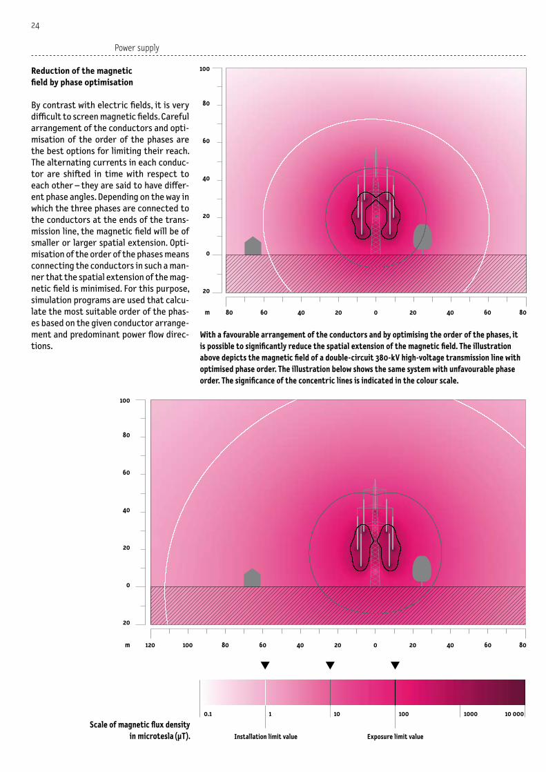
Wireless devices in buildings
Wireless devices such as cordless phones, cordless headphones, baby monitors, WLAN stations, etc., are also being used in residential dwellings to an ever increas-ing extent. Although their transmitting power is often relatively low, these devi-ces can dominate the indoor exposure to high-frequency radiation. > Pages 52 – 55
Index, glossary, references, links, publication data>Page 56
�

Introduction
Electromagnetic spectrum
The diagram here shows an overview of the entire electromagnetic spectrum. Elec-tromagnetic radiation occurs in our nat-ural environment and is also generated artificially in a variety of forms, e.g. elec-tric and magnetic fields from high-volt-age power lines, radiation from mobile phone base stations and radio transmit-ters, visible light, x-rays. In physical terms, these types of radiation are distinguished by their frequency, i.e. the number of os-cillations per second. Depending on their frequency they have different radiation properties and different effects on hu-man beings.
Division of frequency spectrum
The frequency spectrum of electromag-netic radiation is broadly divided into non-ionising and ionising radiation. Non-ionis-ing radiation is divided into low-frequen-cy and high-frequency radiation, infrared radiation, visible light and ultraviolet ra-diation. Artificially produced low-frequen-cy and high-frequency radiation are also referred to as “electrosmog”.
Low-frequency fields
The low-frequency range includes electric and magnetic fields from railway contact lines, high-voltage power lines and elec-trical household appliances. Since the rail-way power supply has a frequency of 16.7 oscillations per second, the fields it pro-duces also have a frequency of 16.7 hertz (Hz). By comparison, the public power sup-ply has a frequency of 50 Hz.
Frequency
1 Hz 1 kHz 1 MHz
Wavelength
300 000 km 300 km 300 m
Low-frequency fields
Railway lines
Mobile telephony
Electricity supply and use
Broadcasting
�

Electromagnetic spectrum
High-frequency radiation
We speak of high-frequency radiation when oscillations are 30,000 per second or more. Here, electric and magnetic fields are coupled and can propagate in the form of a wave. This is used for the wireless transmission of information. Specific ex-amples include transmitters and receivers for radio and television, mobile telephony, point-to-point microwave links and radar. Such equipment uses frequencies ranging from several hundred kilohertz for me-dium-wave radio to several billion hertz (gigahertz) for point-to-point transmis-sion, while heat radiation (infrared) and
visible light have even higher frequencies. Although these are no longer described as “electrosmog”, they nonetheless belong to the category of non-ionising radiation.
Ionising radiation
The transition to ionising radiation occurs in the ultraviolet radiation range. Ionis-ing radiation includes x-rays and gamma radiation. By contrast with non-ionising radiation, ionising radiation possesses suf-ficient energy to directly alter the basic constituents of living organisms (atoms and molecules).
1 GHz 1 THz
30 cm 0.3 mm
Non-ionising radiation
High-frequency fields
Ionising radiation
300 nm
Microwave ovenWLAN
Point-to-point microwave links
Visible lightInfrared Ultraviolet radiation
X-ray
�
Is electrosmog a health hazard?
The negative impacts of intensive non-ionising radiation on our
health have been scientifically established and are undisputed,
but with the exception of workplace accidents, people are never
exposed to such high levels of radiation. However, biological
effects also occur at levels well below internationally recommen-
ded hazard thresholds. Since scientists are unable to indicate
how harmful these effects are, it is advisable to take certain
precautions.
Electrosmog and health
�

Contents
Effects of low-frequency radiation > P 7
Nerve and muscle stimulation > P 7
Subliminal effects > P 7
Increased risk of leukaemia among children? > P 7
Effects of high-frequency radiation > P �0
Hazardous thermal effects > P �0
Numerous non-thermal effects > P �0
Phenomenon of electrosensibility > P ��
Electrosensitivity > P ��
Electrosensibility > P ��
Evaluation of effects of high-frequency radiation > P ��
Explanations > P ��
Effects of low-frequency radiation
Unlike many animals (such as birds and fish), human beings do not possess any sen-sory organs for electric or magnetic fields. The most we can do is perceive them in-directly. For example, some people expe-rience a tingling sensation on their skin when standing directly beneath high-volt-age power lines. Here the alternating elec-tric field causes body hairs to vibrate, and this is perceived as a tingling sensation. While this effect may be perceived as an annoyance, it does not represent any dan-ger to health.
Nerve and muscle stimulation
More intensive electric and magnetic fields are known to be harmful to our health, though we are not normally exposed to these in daily life. For example, extremely intensive magnetic fields over 10,000 mi-crotesla (µT) can cause nerve and muscle cells to malfunction. Such powerful mag-netic fields generate electric currents in the human organism that trigger un-desirable nerve excitations and muscle contractions. And if the heart is exposed to extreme magnetic fields of more than 100,000 µT, this can cause cramping of the heart muscle – a condition that is life-threatening.These effects on nerves and muscles are referred to as stimulation effects. They have been scientifically established and form the basis for defining international hazard thresholds. If these limits are not exceeded, no nerve or muscle cell mal-functions are triggered by low-frequen-cy fields.
Subliminal effects
Various studies have revealed, however, that biological reactions may occur even if field strengths are well below the inter-nationally defined thresholds. These re-actions are referred to as subliminal ef-fects.Experiments conducted on both animals and human beings have identified chang-es in behaviour, interference with learning capacity and impacts on the hormone sys-tem. For example, it has been found that lower than usual levels of the hormone melatonin are produced. Melatonin con-trols the biological day/night cycle, has a
stimulating effect on the immune system and inhibits the growth of tumours. Me-latonin deficiencies are associated with sleep disorders, tiredness and depressive states. Research has also identified a va-riety of other impacts of low-frequency fields, including influences on growth and metabolism of cells and changes in genet-ic material.The existence of subliminal effects is un-disputed, but what we do not know is how they actually occur. Given the present-day status of knowledge, it is difficult to say whether these represent a health hazard, and if so under what circumstances.
Increased risk of leukaemia among children?
Epidemiological studies, which exam-ine the frequency of occurrence of cer-tain diseases among selected population groups, are a means of finding out more about any harmful effects that may be caused by non-ionising radiation. Studies of this sort have been carried out in a va-riety of countries since the early 1980s in order to determine whether low-fre-quency magnetic fields may cause or fa-vour the development of cancer. For many years, the findings were varied and often contradictory, but as a result of more re-cent investigations and meta-analysis of earlier ones, researchers have meanwhile come to a uniform conclusion: the risk of contracting leukaemia is possibly twice as high among children who are exposed to magnetic fields over 0.4 µT for lengthy periods.The International Agency for Research on Cancer (IARC) also came to the same con-clusion, and in 2001 it classified low-fre-quency magnetic fields as potentially car-cinogenic for human beings. It is of the opinion that weak magnetic fields repre-sent a possible – though not probable or proven – leukaemia risk. In Switzerland, around 60 children a year contract leukaemia. If long-term expo- sure to low-frequency magnetic fields of more than 0.4 µT really were to double the risk of children contracting leukaemia – which admittedly has not yet been defini-tively established – this means that about 1 new case a year would be attributable to magnetic fields, while the remaining 59 would be attributable to other causes.The suspicion of a higher leukaemia risk is one reason to keep long-term exposure
7

to low-frequency magnetic fields as low as possible as a precautionary measure. In-sofar as electrical household appliances are the source, we ourselves are able to influence the level of exposure in our own homes. In contrast, electrical systems in our environment are subject to the provi-sions of the Ordinance relating to Protec-tion from Non-Ionising Radiation, which entered into effect on 1 February 2000, and stipulates precautionary measures to reduce magnetic fields at locations oc-cupied by people for lengthy periods of time, including residential dwellings, of-fices, schools, hospitals and playgrounds. At these locations, the installation limit value for all new high-voltage power lines and transformer stations at full load is 1 µT. However, long-term exposure is gen-erally well below this level, since these sys-tems seldom operate at full capacity.
Low-frequency fields
In our daily life we are exposed to non-ionising radiation from a broad variety of sources. For example, railway catenaries, electricity supply systems and electrical household appliances all produce low-frequency electric and magnetic fields. If these are of high intensity, they can produce electric currents in the body that trigger undesirable nerve stimulations or muscle contractions.
�
Electrosmog and health

High-frequency fields
TV and radio transmitters, mobile phone base stations, radar installations and microwave ovens all produce high-frequency radiation. This has different physical properties to low-frequency fields and its effects on human beings are also quite different. Intensive high-frequency radiation is converted in the body into heat, and this can harm sensitive organs. More research is required in order to clarify effects of low-level radiation.
�

Electrosmog and health
Effects of high-frequency radiationWhen we use a microwave oven, we are in fact utilising the heat produced by inten-sive high-frequency radiation. Here, bio-logical tissue such as vegetables and meat absorbs the radiated energy and heats up. It is not only microwaves that heat up biological tissue, however: this pro- cess occurs as the result of high-frequency electromagnetic radiation from all sour- ces – for example, radio and mobile phone transmitters – but it only occurs if the radiation is of sufficient intensity. Many biochemical reactions in the human body only take place within a narrow tem-perature range. Diseases accompanied by high fever show us that these processes can already be severely disturbed if the body temperature rises by only a few de-grees Celsius. For this reason, thermal im-pacts due to electromagnetic radiation have to be regarded as undesirable.
Hazardous thermal effects
In daily life we are normally not exposed to high-frequency radiation of such inten-sity that its thermal effects could harm our health. A health risk arises if our body tempera-ture increases by more than 1 to 2° C as a result of absorbed radiation. The resulting effects are similar to those experienced due to fever or overheating: memory dis-orders, interference with various bodily functions, including the reproductive or-gans. Organs that have poor blood flow and are therefore unable to cool quickly are es-pecially at risk (e.g. the eyes, which can de-velop cataracts). If our body temperature increases even more, this can lead to inter-nal burns or even death due to heat stroke.
Intensive electromagnetic radiation can cause the body to heat up, and this results in symptoms similar to fevers. The limit values specified by the ONIR protect us against these undesirable thermal effects.
Well-documented work accidents abroad, especially those involving radar equip-ment, demonstrate how dangerous high-frequency radiation can be. For example, a mechanic who inadvertently strayed very close to a radar transmitter suddenly felt very hot and suffered internal burns. He and two of his colleagues had to be tak-en to hospital with skin damage and se-vere coagulation problems. All three com-plained of tiredness, dizziness, headaches and pressure above the eyes. Scientists are well aware of these acute effects of intensive high-frequency radiation, which only occur above a certain level of radia-tion intensity. The corresponding thresh-old forms the basis for the definition of internationally recognised limits aimed at protecting the population against the harmful effects of short-term exposure.
Numerous non-thermal effects
Various studies have revealed, however, that biological effects may result even if radiation intensities are well below the internationally defined thresholds. Since they do not increase our body tempera-ture, we refer to them as non-thermal ef-fects. Experiments on test subjects have demon-strated, for example, that radiation from mobile phones can influence brain waves and sleep patterns. In laboratory stud-ies, behaviour changes among animals, and physiological changes in cell cultures, have been observed as the result of low-inten-sity, high-frequency radiation. Epidemiological studies have also given rise to certain suspicions: studies carried out in the vicinity of TV and radio trans-
mitters have yielded higher leukaemia and lymphoma rates than expected. However, findings are not uniform and some stud-ies have methodological flaws.To some extent, indicators of potential impacts on health come directly from the population. For example, an increasing number of people living in the vicinity of a now decommissioned short-wave radio transmitter in Schwarzenburg (canton of Bern) began to complain about nervous- ness, restlessness, insomnia, general weak-ness, tiredness and aching limbs, and a subsequent epidemiological study con-ducted on behalf of the federal govern-ment revealed a statistical correlation between sleep disorders and transmis-sion patterns. However, the study was un-able to definitively determine whether the various symptoms were in fact attributa-ble to radiation from the transmitter, or whether confounding factors might have been involved. Nonetheless, the fact that high-frequen-cy radiation gives rise to non-thermal ef-fects is undisputed. The problem is, we do not yet know how these effects come into being. Given the present-day status of knowledge, it is also difficult to say wheth-er these effects represent a health haz-ard, and if so, under what circumstances. In view of the existence of contradictory findings and the fact that not all experi-ments can be successfully repeated, it is difficult to make a meaningful evaluation. This means that further research is essen-tial if we are to gain an accurate picture of the impacts of low-intensity, high-fre-quency radiation on our health.
�0

Phenomenon of electrosensitivityHuman beings do not possess a sensory or-gan that enables them to directly perceive non-ionising radiation, but it appears that some especially sensitive people are able to perceive even very weak electromag-netic fields. Others feel certain that their health related symptoms are caused by electrosmog.
Perception of weak electromagnetic fields
Some people have the ability to conscious-ly perceive weak electromagnetic radia-tion, which can be established in experi-mental arrangements and tests.Test sub-jects have to be able to tell the difference between a real and a sham exposure. Ap-proximately 5 percent are able to accom-plish this better than they could be ex-pected to by chance. The ability to per-ceive weak electromagnetic fields does not mean, however, that the person con-cerned also suffers due to electrosmog.
People with electrosensitivity feel impaired by low intensity non-ionising radiation, even when the level is well below internationally recognised exposure limit values. The symptoms tend be non-specific, for example tinnitus (ringing in the ears).
In this scientific experiment, the subject’s head is being exposed to electromagnet-ic fields similar to those produced by mobile phones. Exposure for only 30 minutes already alters our brain activity, but it is at present not possible to draw any clear conclusions from this with respect to potential harm to health.
Electrosensitivity
The term electrosensitivity (or electro-magnetic hypersensitivity) is used when someone attributes his or her health problems to the effects of low-intensity non-ionising radiation. Here, people com-plain of frequent but non-specific symp-toms such as sleep disturbances, head-aches, nervousness, general tiredness, lapses of concentration, tinnitus (ringing in the ears), dizziness, aching limbs, heart pains. As a rule, it is difficult to precisely deter-mine the causes of these symptoms. In ad-dition to electrosmog, a variety of other factors come into question, such as stress, noise, flickering light, chemicals, and phys-ical or mental disorders. Furthermore, there are no generally acknowledged cri-teria for an objective diagnosis of electro-sensitivity, and it also appears that ability to perceive weak fields and electrosensi-tivity exist independently of one another. This means that people with electrosensi-tivity do not necessarily have a higher per-ception of electromagnetic fields than av-erage, and vice versa. Many questions still need to be answered regarding these two phenomena, and therefore a great deal of research is still required.
��

Evaluation of effects of high-frequency radiation
Serious
Thermal effects (e.g. interference with memory and other functions, cataracts, internal burns)
Leukaemia / lymphomasBrain tumours
MortalityOther types of tumour
StillbirthGenotoxicityBreast cancerEye tumoursTesticle tumours
Non-specific symptoms (headaches, fatigue, problems of concentration, disquiet, burning skin, etc.)
Quality of sleepElectromagnetic hypersensitivity
Mental symptomsUnspecific symptoms (insomnia, headaches, etc.)
Brain activitySleep phases
Cognitive functions, reaction times
Hormone systemImmune systemHigh blood pressure
Established
Probable
Possible
Improbable
Not assessable
Evidence
Reduced well-being Relevance to health unknown
Effects
��
Electrosmog and health

Secondly, the relevance of the effects to hu-man health was evaluated, regardless of their indicated degree of certainty:
Serious: The effect concerned represents a drastic restriction of quality of life. It is life threatening and will shorten life expectancy.
Reduced well-being: The effect significant-ly restricts quality of life and well-being, but the symptoms are not directly life threaten-ing.
Relevance to health unknown: The effect is physiologically measurable, but the ob-served changes are within the normal varia-bility range of healthy individuals. Since it is normally not perceived, it does not represent an acute health risk, nor does it have an im-pact on quality of life. However, it is not clear whether it could lead to a health risk in the longer term.
The table on pages �� and �� is largely based on a study entitled “High frequency radia-tion and human health”, published in �00� and updated in �00� (BUWAL UM-���-D), which was produced by the Institute for Social and Preventive Medicine, Basel, on behalf of the Swiss Agency for the Environment, Forests and Landscape. It presents a differentiated assessment of the findings from more than �00 studies.
The “evidence” column indicates the degree of certainty of each effect. For this purpose it has been divided into the following categories:
Established: The effect concerned is able to stand up to strict scientific examination.
Probable: The effect concerned has been established in a variety of studies, the quality of which is high enough to permit the exclu-sion of other influencing factors with a high degree of certainty, but a plausible causation mechanism is nonetheless lacking.
Possible: The effect concerned has been observed in various studies, but the findings are not consistent. Reports concerning indi-vidual cases support the scientific indicators.
Improbable: There are no indicators for the effect concerned, but multiple indicators of its absence.
Not assessable: The available data are insuf-ficient for making a meaningful assessment.
Various, above exposure limit values
Mobile phones
Mobile phonesMobile phones
TV / radio transmittersMobile phonesRadio transmittersMobile phones
Mobile phones
Mobile phonesVarious
Diathermy devicesWorkplace exposureVariousMobile phonesRadar gunsVariousMobile phone base stations
VariousVariousRadio transmitters
Source of exposure
��
Explanations concerning the table on pages 12 and 13

Ordinance
Regulations to protect the population against the effects of electrosmog
The Ordinance relating to Protection from Non-Ionising Radia-
tion (ONIR), which entered into effect on 1 February 2000, is
intended to protect Switzerland’s population against the effects
of electrosmog. To provide protection against known and scien-
tifically established risks, it specifies limit values for short-term
exposure. In addition, precautionary installation limit values
for a variety of radiation sources help reduce long-term expo-
sure in residential areas.
��

Contents
Protection concept > P ��
Scope of application of the Ordinance > P ��
Limitation of short-term exposure > P ��
Exposure limit values > P ��
Precautionary limitation of long-term exposure > P �7
Installation limit values > P �7
Places of sensitive use > P �7
New building zones > P ��
Controls by means of calculations and measurements > P ��
Approval measurements > P ��
Control measurements > P ��
Measurement of radiation from mobile phone base stations > P ��
Wherever we may be, non-ionising radi-ation is all around us. It is produced by all electrical installations and applian- ces, and by transmitters of all kinds. As ad-vances in technology continue to be made and use of these devices at the workplace and in the private sphere broadens, ex-posure to non-ionising radiation is likely to increase further. On 1 February 2000 the Federal Council enacted its Ordinance relating to Protection from Non-Ionising Radiation (ONIR) as an instrument to pro-tect the population against the known and suspected harmful effects of elec-trosmog.The scope of application of this Ordinance is limited to stationary sources of radia-tion such as power lines, transformer sta-tions, railway catenaries and transmitters for mobile communication, broadcasting and radar. By contrast, it does not cov-
er mobile phones, cordless phones, mon-itors, screens, microwave ovens and oth-er electrical appliances. To limit radiation from the above appliances, internationally recognised regulations and standards are required that Switzerland cannot draw up unilaterally. Non-ionising radiation must not be al-lowed to harm the health and well-being of the country’s population, and the Ordi-nance pursues this objective in two ways: – It limits short-term exposure in order
to prevent scientifically accepted dam-age to health.
– As a precautionary measure, it also re-duces long-term exposure in order to provide protection against potential (i.e. not yet scientifically established) health risks.
Scope of application of the ONIR
Systems covered by the ONIR:
– High-voltage power lines (overhead and underground)– Transformer stations– Sub-stations and switchyards– Domestic electrical installations – Railways and tramways– Mobile phone base stations– Point-to point microwave links– Wireless local loops (WLL)– Broadcasting installations– Professional mobile radio installations– Amateur radio systems– Radar installations
The ONIR contains regulations governing stationary installations that produce non-ionising radiation in the frequency range from 0 hertz to 300 gigahertz.
Systems not covered by the ONIR:
– Mobile phones– Cordless phones– Bluetooth– Microwave ovens– Hotplates– Electrical appliances (TV sets, computer monitors, clock radios, hairdryers, shavers, clothes irons, etc.)– Medical devices– Equipment at the workplace
Stationary installations like the mobile phone antenna in the background have to comply with the limit values specified by the ONIR. Here the electromagnetic radiation is being measured with the aid of a calibrated hand-held antenna.
Protection concept
��

Limitation of short-term exposure
The Ordinance specifies exposure limit val-ues aimed at limiting short-term expo-sure. These limits are based on the recom-mendations of the International Commis-sion on Non-Ionising Radiation Protection (ICNIRP) that are used in many other coun-tries. If these limits are complied with, none of the scientifically accepted nega-tive effects on our health can occur. These include an increase in body temperature due to very high intensity radiation from transmitters, and triggering of undesira-ble nerve impulses or muscle contractions by intensive electric or magnetic fields. The exposure limit values must be com-plied with wherever people spend any length of time.
Exposure limit values
– The exposure limit values specified by the Ordinance are internationally co-ordinated.
– They protect against scientifically accepted damage to health.
– They take account of the overall low-frequency or high-frequency radiation
at a given location.– They must be complied with wherever people spend any length of time (including
very short periods).
System Frequency Exposure limit value
Railway catenaries 16.7 Hz 300 μT and 10,000 V/mHigh-voltage power lines 50 Hz 100 μT and 5,000 V/mRadio/TV transmitters 10 - 400 MHz 28 V/mMobile phone 900 MHz 41 V/m base stations 1,800 MHz 58 V/mUMTS transmitters 2,100 MHz 61 V/m
Examples of exposure limit values for various frequencies.
Ordinance
The exposure limit values for the electric field strength (green curve) specified in the ONIR vary according to the frequency of the radiation, since the effects on human beings occur at different intensities depending on frequency.
For the same reason, the exposure limit values for the magnetic flux density (red curve) are also frequency-dependent.
1 Hz
100 kV/m
10 kV/m
1 kV/m
100 V/m
10 V/m
1 V/m
1 kHz 1 MHz 1 GHz 1 THz
Elec
tric
fiel
d st
reng
th
Frequency
Mag
neti
c flu
x de
nsit
y
1 Hz
100 mT
10 mT
1 mT
100 μT
10 μT
10 nT
1 kHz 1 MHz 1 GHz 1 THzFrequency
100 nT
1 μT
��

Installation limit values
– The installation limit values specified by the ONIR are of a precautionary nature.– They are much lower than the exposure limit values.– They are based on the principle of precaution established in the Federal Law
relating to the Protection of the Environment, and have been specified in
accordance with technical, operational and economic criteria. – They limit the level of radiation from a given installation. – They must be complied with wherever people spend lengthy periods of time.– They ensure that exposure to electrosmog
is low at places of sensitive use, and in this way they also reduce the risk of suspected harmful effects on health.
Installation limit values are based on tech-nical, operational and economic criteria, and not on medical or biological findings. This means they are not levels indicating harm-lessness, and compliance with them cannot guarantee that all harmful effects can be excluded. However, this also does not mean that negative effects occur if installation limit values are exceeded.
System Frequency Installation limit value
Railway catenaries 16.7 Hz 1 μT (24-hr average)High-voltage power lines 50 Hz 1 μTRadio/TV transmitters 10-860 MHz 3 V/mMobile phone 900 MHz 4 V/mbase stations 1,800 MHz 6 V/mUMTS base stations 2,100 MHz 6 V/m
Examples of installation limit values. These have to be complied with in the reference operating mode. Please refer to the descriptions of the various installation categories for more detailed information.
Places of sensitive use
Precautionary protection provided by the installation limit values is limited to locations where people regularly spend lengthy periods of time. Here, long-term exposure shall be kept as low as possi-ble. Places of sensitive use include apart-ments, schools, hospitals, offices and play-grounds, but do not include balconies and roof terraces, stairways, garages, storage and archive rooms, temporary workpla- ces, churches, concert halls and theatres, camp sites, sports and leisure-time facil-ities, passenger areas in railways, obser-vation decks.
Precautionary limitation of long-term exposure
Exposure limit values ensure protection against recognised, acute effects, but they do not protect against suspected effects at lower radiation intensities, es-pecially with long-term exposure. A great deal of research is still required in this area. When the Federal Council drew up the ONIR, it did not want to wait for fur-ther research findings, and for this rea-son it included precautionary measures to limit the long-term exposure. The provisions concerned are based on the principle of precaution as established in the Federal Law relating to the Protec-tion of the Environment. Article 1, para-graph 2 of this law states: “Early preven-tive measures shall be taken in order to limit effects which could become harmful or a nuisance”. In other words, suspicion of harmful effects is sufficient, and it is therefore not necessary to provide scien-tific proof. In Article 11, the Environmen-
tal Protection Law also states that meas-ures must be taken at the source to limit environmental pollution. Here the criteria are technical and operational feasibility, as well as economic acceptability. The ONIR implements these principles by specifying thresholds for various catego-ries of radiation sources. These so-called installation limit values apply to radiation from a single installation and are well be-low the exposure limit values. For mobile phone base stations they are around 10 times lower, and in the case of new high-voltage power lines they are as much as 100 times lower. Installation limit values must be complied with wherever people spend lengthy periods of time (at plac-es of sensitive use). These provisions are among the most stringent regulations of their kind in the world. However, in view of the unclear situation with respect to risks to health, even these stringent regulations do not provide 100-percent safety. It is not possible for au-thorities and medical experts to provide a guarantee of safety, either now or in the future. However, this holds not only for the radiation issue, but also for many other new technologies. It is not possible to ex-clude all potential health risks on a sci-entific basis, since life processes are too complex to allow every conceivable biolog-ical effect to be studied in advance. But since the installation limit values reduce long-term exposure, the risk of any conse-quences to our health that are not clearly recognisable today is also minimised.
�7

Controls by means of calculations and measurements
The competent federal, cantonal or mu-nicipal authorities verify whether the lim-it values specified by the Ordinance are complied with. For this purpose they may carry out calculations or measurements.For example, operators of mobile phone base stations are required to submit a site data sheet together with their application for a building permit. The radiation in the vicinity of the installation is calculated on the basis of the transmission capacity and directions. The cantonal or municipal authorities check the accuracy of these data and calculations. Similar calculations are also carried out on other installations such as high-voltage power lines and rail-way catenaries.The radiation can be measured after the system has been put into operation. Here a distinction is made between approval and control measurements.
Approval measurements
Approval measurements are carried out in order to ascertain that the respective in-stallation limit value is complied with in a given operating mode – in the case of mo-bile phone base stations, for example, at full utilisation capacity and maximum ap-proved transmission power. These meas-urements are normally carried out if cal-culations indicate that radiation levels are likely to exceed 80 percent of the speci-fied installation limit value. It is often the case that the proprietor of the facility entrusts a specialised company with the task of carrying out these measurements, since such companies possess the neces-sary know-how and experience. The asso-ciated costs have to be borne by the pro-prietor in accordance with the principle of “polluter pays”.Approval measurements can never be car-ried out fully independently of the propri-etor, since the latter is required to pro-vide the necessary data concerning the current operating mode during the meas-urement procedure. In the case of mobile phone base stations, the Ordinance stipu-lates that the installation limit value must be complied with at full operating capaci-ty and maximum transmission power. This status seldom applies in practice, however,
Ordinance
New building zones
In addition to measures at source, the ONIR also sets out to ensure the lowest possible long-term exposure by means of land use planning. It restricts the develop-ment zoning of new areas if they are in the close vicinity of existing or planned facil-ities that produce non-ionising radiation. In this way it ensures that no heavily ex-posed places of sensitive use will be cre-ated in the future. Since 1 February 2000, the definition of new building zones is only permitted if the installation limit values can be complied with. The situation is different, however, in building zones that were approved before the above date and are located near a ra-diation source. Here, development is per-mitted without any restrictions, even if an installation limit value is exceeded. How-ever the installation concerned has to be improved, and the ONIR specifies the re-quired degree of improvement for each type of installation.
For example, mobile phone base stations must be improved in such a manner as to ensure that the installation limit value is fully complied with at all places of sensi-tive use, but no such requirements apply to power lines and railway catenaries. In the case of electricity transmission, the Ordinance merely calls for optimisation of the phasing arrangement, and in the case of catenaries a return conductor is required. Even though these measures do not suffice to bring the level of radiation below the installation limit value in devel-oped areas, the Ordinance does not call for any other improvements. The Federal Council was of the opinion that a reduc-tion of radiation levels to below the instal-lation limit value would be disproportion-ate for existing power lines and catenar-ies. For the same reason it also rejected the idea of reversing zoning in areas that are already zoned.
In order to protect the population, the designation of new building zones will only be permitted in close proximity to existing or planned supply installations emitting non-ionising radiation if the installations concerned are able to comply with the installation limit values specified in the ONIR.
��

Measurement of radiation from mobile phone base stations
There are various methods for measuring radiation from mobile phone base stations:
Broadband measurement: With this method, a sensor is used which records the overall radiation in a broad frequency range. Along-side mobile phone base stations, other systems such as radio and TV transmitters also contribute towards these readings, but it is not possible to distinguish between the individual sources.
Frequency selective measurement: This method is used if, on the basis of a broadband measurement, it is not possible to judge with sufficient certainty whether a mobile phone base station complies with the installation limit value. Here it is only the radiation from the installation concerned that is measured. Selective frequency measurements are more demanding and time-consuming than broad-band measurements, and require more com-plex measuring equipment.
Code selective measurement: This method is used for measuring UTMS radiation if the other two methods fail to yield conclusive results. Here, only the temporally constant proportion from the UMTS signal is recorded, and subsequently projected. In this way it is possible to clearly allocate the recorded signals to a specific transmitter.
since the base station normally operates at lower output levels. For this reason, the results have to be projected from the cur-rent to the maximum approved transmis-sion power. It is only in this way that the authorities are able to judge whether the installation limit value has been complied with. These projections are based on data provided by the operator concerning the current operating mode.
Control measurements
Control measurements are carried out for a quite different purpose, namely to de-termine the radiation level when the in-stallation concerned is in its actual state of operation. Control measurements are carried out independently of the oper-ator. This hand-held test antenna (above) can be used for detecting the maximum exposure level
indoors. A spectrum analyser (below) depicts the results of the frequency selective measure-ment. Since each frequency is recorded separately, it is possible to specifically measure the level of radiation from a single mobile phone base station.
��

Power supply
Wherever there is an electric current, there are also low-frequency fields
Wherever electricity is generated, transmitted and consumed,
electric and magnetic fields are created as by-products. The
higher the current and voltage, and the shorter the distance
from the current-bearing installations, the higher the intensity
of these fields becomes. In the area of power supply, the highest
levels of exposure occur in the immediate vicinity of transformer
stations and high-voltage power lines.
�0

Contents
From power plant to mains socket > P ��
The three parameters of electricity > P ��
How fields are created > P ��
Three-phase alternating current > P ��
Magnetic fields from overhead power lines > P ��
Reduction of the magnetic field by phase optimisation > P ��
Temporal variation of the magnetic field near a high-voltage transmission line > P ��
Electric fields from overhead power lines > P ��
More localised magnetic fields from underground cables > P ��
Precautionary regulations of the ONIR > P ��
Magnetic field from a transformer station > P �7
From power plant to mains socket
In Switzerland, a large proportion of electricity is produced from hydropow-er plants that are often located well away from places where it is subsequently con-sumed. This means that much of the en-ergy we consume has already travelled a considerable distance. Generators in the various types of power plants generate electricity with a frequency of 50 Hz and a voltage of 6 to 27 kilovolts (kV). High voltages reduce transmission loss-es, and in view of this, the voltage is in-creased in the respective power plant by means of transformers before the elec-tricity is fed into the transmission grid. As a rule, levels of 220 or 380 kV are used for long-distance transport. This overland network mainly comprises overhead lines supported by pylons.
For shorter distances (e.g. region to re-gion), the voltage is reduced to between 50 and 150 kV and the energy is usually transported via overhead lines support-ed by concrete masts. And at the local level, the voltage is re-duced to between 6 and 30 kV and the en-ergy is transported either by underground cables or via overhead lines supported by wooden poles.In residential areas, villages, etc., trans-former stations finally reduce the voltage to the levels normally used in households (i.e. 230 and 400 volts).
National transmission grid,
380 or 220 kV
Sub-stationPower plant
Pole mounted transformer
Cable distribution cabinet
Transformer station
Consumers
Sub-station
Interregional dis-tribution networks, 50 to 150 kV
Regional distribution
networks, 6 to 30 kV
Local distribution networks,
230 V / 400 V
On its way from power plant to end user, electricity first has to be converted to higher voltages, then brought back down to lower voltages. Electric and magnetic fields are produced both along power lines and in the vicinity of transformer stations.
��

Power supply
The three parameters of electricity
There are three physical parameters which characterise electricity:
Current: This is measured in amperes (A) and indicates how much electricity is flowing through a conductor. If we use water supply as an analogy, the current would correspond to the throughput of water per time unit. The greater the throughput, the higher the current. In households, fuses in distribution boxes or panels limit the current to �0 or �� A. The largest high-voltage power lines are designed for currents of up to �,�00 A.
Voltage: This is measured in volts (V). To stay with the water supply analogy, this is equiva-lent to water pressure, which is still present even if the tap is turned off and no water is flowing. In the same way, a plugged-in power cable, e.g. for a bedside table lamp, is “live”, even if the light is switched off and no electricity is flowing. General purpose batteries range from �.� to �� V. The mains supply in households is ��0 V, while high-volt-age power lines can be up to ��0,000 V.
Frequency: This refers to the number of oscillations per second, and it is measured in hertz (Hz) (� Hz = � oscillation per second). Frequency is only of importance for alternat-ing current. With batteries, the positive and negative poles are fixed. They supply direct current that always flows in the same direc-tion. By contrast, alternating current chang-es its flow direction: electricity in households has a frequency of �0 Hz. And this frequency is always the same, from the power plant to the mains socket, whereas voltage and current change according to network level.
Three-phase alternating current
The �0 Hz electricity network is operated with three-phase alternating current. Here, three phase conductors form one line circuit. The alternating currents in each conductor are phase shifted by one-third of an oscilla-tion period – they have differing phase an-gles. There are six different possible combi-nations for connecting the three phases (R, S and T) to the three phase conductors of a line circuit. As long as there is not a
second circuit nearby, all six combinations generate an equally strong magnetic field. But as soon as two line circuits are brought close together, the magnetic fields of the individual circuits can be mutually strength-ened or weakened. This depends on how the order of the phases of the second line circuit has been arranged in relation to the first one.
How fields are created
Everyday we use electrical appliances and devices at home, at work and in our leisure time. And wherever electricity is used, electric and magnetic fields are cre-ated – for example in close proximity to high-voltage power lines, sub-stations and transformer stations. But these fields are also created by electrical appliances in households, offices, factories, etc. Electric fields occur as soon as an appli-ance is connected to the power supply via a cable and plug. As soon as it is switched on, current begins to flow, and this gives rise to a magnetic field in addition to the already existing electric field. Since our power supply is operated with alternat-ing current with a frequency of 50 Hz, the electric and magnetic fields are also 50 Hz alternating fields.
Some of the properties of electric and magnetic fields are similar: for example, in both cases they weaken rapidly with in-creasing distance from the source. How-ever, they differ greatly when it comes to screening: electric fields can be screened fairly easily, whereas magnetic fields free-ly penetrate practically all materials, and screening is therefore only possible with the aid of special metal alloys or thick alu-minium sheets, and even then only to a limited extent.
0 5 10 15 20
R S T
Curr
ent (
ampe
res)
Time (milliseconds)
With the three-phase alternating current system, the currents in the three conductors are each phase shifted by one-third of an oscillation period. The three phases are designated R, S and T.
��

Magnetic fields from overhead lines
The intensity of a magnetic field is indi-cated in microtesla (µT). With high-voltage power lines, the higher the current, and the greater the distances between the power-bearing conductors, the greater the spatial bearing of the magnetic field. The most intensive exposure occurs at mid-span between two pylons, where the conductors are closest to the ground. The level varies, however, according to the de-sign of the power line and the current. The magnetic field weakens with increasing distance from the power line. This means that the higher the conductors are above the ground, the weaker the field. In the case of transmission lines with several line circuits, or power lines running parallel to one another, the magnetic fields of the individual circuits can be mutually weak-ened or strengthened. Therefore it is pos-sible to reduce the intensity of the mag-netic field by optimising the order of the phases.The walls of buildings cannot screen mag-netic fields effectively. 380 kV overhead power lines can increase exposure to mag-netic fields in neighbouring houses locat-ed up to a distance of 150 to 200 metres. Further away, exposure approaches the normal background level of approximately 0.02 to 0.04 µT which is usually encoun-tered in residential dwellings connected to the electricity mains. However, the in-tensity can be much higher in the close vi-cinity of electrical appliances.
Cross-section of the magnetic field of the high-voltage transmission line depicted above, at mid-span between two pylons where the conductors are closest to the ground. The exposure diminishes with increasing distance from the power line, and is not influenced by walls, trees or the ground. The significance of the concentric lines is indicated in the colour scale below.
View (in perspective) of the magnetic field of a typical 380-kV high-voltage transmission line with two line circuits at full load (1,920 A). The highest exposure occurs around the six current-bearing conductors: within the red tubes the level is more than 100 microtesla (μT), and at the perimeter of the large tunnel it has fallen to 1 μT.
0
0 20 40 60 8020406080
20
40
60
80
100
m
20
20
Scale of magnetic flux density in microtesla (μT).
Installation limit value Exposure limit value
0.1 1 10 100 1000 10 000
��
Power supply
Reduction of the magnetic field by phase optimisation
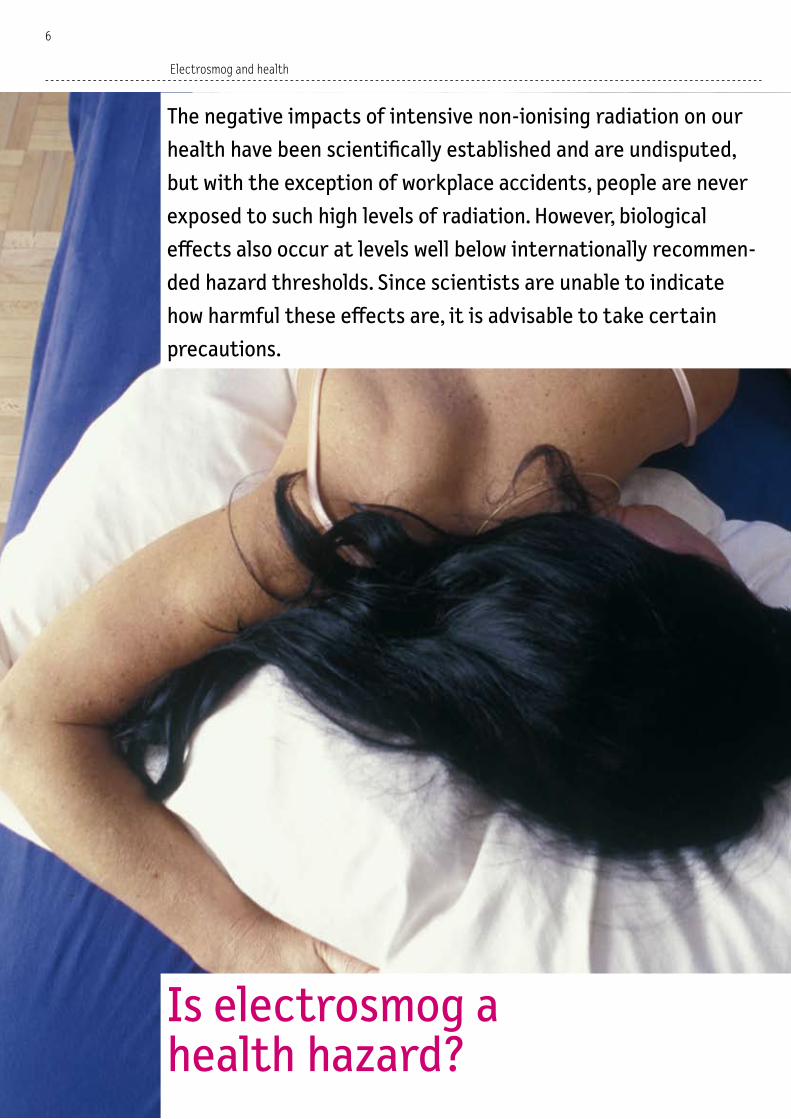
By contrast with electric fields, it is very difficult to screen magnetic fields. Careful arrangement of the conductors and opti-misation of the order of the phases are the best options for limiting their reach. The alternating currents in each conduc-tor are shifted in time with respect to each other – they are said to have differ-ent phase angles. Depending on the way in which the three phases are connected to the conductors at the ends of the trans-mission line, the magnetic field will be of smaller or larger spatial extension. Opti-misation of the order of the phases means connecting the conductors in such a man-ner that the spatial extension of the mag-netic field is minimised. For this purpose, simulation programs are used that calcu-late the most suitable order of the phas-es based on the given conductor arrange-ment and predominant power flow direc-tions.
With a favourable arrangement of the conductors and by optimising the order of the phases, it is possible to significantly reduce the spatial extension of the magnetic field. The illustration above depicts the magnetic field of a double-circuit 380-kV high-voltage transmission line with optimised phase order. The illustration below shows the same system with unfavourable phase order. The significance of the concentric lines is indicated in the colour scale.
0
0 20 40 60 8020406080
20
40
60
80
100
m
20
0 20 40 60 80m 20406080100120
0
20
40
60
80
100
20
Scale of magnetic flux density in microtesla (μT). Installation limit value Exposure limit value
0.1 1 10 100 1000 10 000
��

Electric fields from overhead power lines
The strength of electric fields is meas-ured in volts per metre (V/m). It largely depends on the voltage and the distance from the conductor. Directly beneath a 380-kV high-voltage power line, the elec-tric field strength close to the ground can reach 5,000 V/m. The lower the voltage, the less intense the electric field. For ex-ample, beneath a 220-kV line the strength is up to 3,000 V/m, for 110-kV lines it is a maximum of 700 V/m and for lines below 50-kV it is up to 400 V/m. As the diagram shows, the field strength weakens with in-creasing distance from the conductors. Electric fields can be distorted and weak-ened by low-conductive materials such as trees, bushes and buildings. The conduc-tivity of building materials usually suffices to reduce an external electric field by 90 percent or more inside the building.
Cross-section of the electric field of a 380 kV high-voltage transmission line with two circuits, at mid-span between two pylons where the conductors are closest to the ground (minimum permissible distance from the ground). Directly below the power line, the exposure limit value of 5,000 volts per metre is almost reached. Buildings, trees and the ground distort electric fields and attenuate them. This means that exposure inside buildings from overhead power lines can be more or less ignored. The significance of the concentric lines is indicated in the colour scale below.
0
0 20 40 60 8020406080
20
40
60
80
m
Example of a 24-hour profile of the magnetic field near a 220 kV high-voltage transmission line on a weekday in January. The magnetic field fluctuates depending on the currents flowing through the two line circuits
Temporal variation of the magnetic field near a high-voltage transmission line
The magnetic field depends on the current, and thus on the corresponding electric-ity consumption in households, industry, etc. The time profile of magnetic field ex-posure in the vicinity of high-voltage pow-er lines thus reflects the fluctuating elec-tricity consumption, depending on time of day and season. Unlike current, the voltage remains prac-tically constant, and this also applies to the electric field of high-voltage power lines, which stays proportional to the volt-age.
100
0.5 μT
0.4 μT
0.3 μT
0.2 μT
0.1 μT
0.0 μT
0 h 2 h 4 h 6 h 8 h 10 h 12 h 14 h 16 h 18 h 20 h 22 h 24 h
Scale of electric field strength in volts per metre (V/m).
Exposure limit value
5 50 500 5000 50 000 500 000
��

Power supply
Precautionary regulations of the ONIR
The precautionary emission limitations for high-voltage transmission lines spec-ified in the ONIR vary according to wheth-er the installation is new, to be modified or old. New installations: At places of sensitive use such as residential dwellings, the in-stallation limit value for new high voltage power lines or upon replacement of exist-ing ones is 1 microtesla (µT). This limit ap-plies to operation of the power line at full capacity. Since current varies according to time of day and season, and only rare-ly reaches full load, the average magnetic field exposure when the installation lim-it value is complied with is well below 1 µT. In certain exceptional circumstances, the relevant authorities may allow this limit value to be exceeded. Installations to be modified: The term “modified” refers to all changes concern-ing conductor arrangement, phase order or operating status of an existing high-voltage power line. At places of sensitive use at which the installation limit value of 1 µT was already exceeded prior to the implemented changes, the magnetic field intensity may not be increased. At all oth-er places of sensitive use, the installa-tion limit value must be complied with. As with new installations, exceptions may be granted under certain circumstances.
Old installations: If old power lines exceed the installation limit value at places of sensitive use, the phasing has to be op-timised. Beyond this the Ordinance does not specify any additional requirements. If the power line concerned does not com-ply with the installation limit value even after optimisation of phasing, this is tol-erated.
The cited direct distances from the con-ductors apply when phasing is optimised. The higher the conductors are suspend-ed, the shorter the minimum lateral dis-tance for compliance with the installa-tion limit value.
More localised magnetic fields from underground cables
Whereas long-distance electricity trans-mission is primarily effected via overhead power lines, most local distribution is now carried out using underground cables.With overhead lines, the air between the conductors acts as an insulator. The con-ductors have to be a certain distance apart in order to prevent arcing. But with underground cables, the conductors are very well insulated and can therefore be placed closer together, as a result of which the reach of the magnetic fields is reduced. This means that, compared with overhead power lines carrying the same current, the magnetic field of an underground ca-ble system has a much smaller spatial ex-tension. Although the exposure may be
just as high directly above an underground cable system as it is immediately beneath an overhead power line, it decreases more quickly on departing laterally than is the case with overhead lines.Unlike the magnetic field, the electric field is completely shielded by the cable sheath and the soil. This means that no electric field is detectable even if we are standing directly above the underground cables.Today it would be technically feasible to also lay high-voltage power lines (over 50 kV) underground, but the associated costs would be much higher, and repair work would be more costly and time-con-suming. In view of this, electricity sup-ply companies prefer to use overhead systems.
Cross-section of the magnetic field of an underground cable line. Here the conduit is 0.8 metres below the surface. Since the current-bearing conductors (745 A each) are close together, the spatial extension of the magnetic field is significantly smaller than is the case with overhead transmission lines, and the exposure also diminishes more quickly with increasing distance.
0
0369
2
4
6
– 2
– 4
93 6m
View (in perspective) of an underground cable line with three conductors in separated plastic tubes embedded in concrete.
220 kV overhead transmission line near Laax (canton of Grisons).
��

Magnetic field from a transformer station
Transformers increase or decrease volt-ages. They are used in power plants, sub-stations, residential areas and industrial zones. Transformer stations in residential areas are fed via the regional electrici-ty distribution network. They change the supply voltage (which ranges from 6,000 up to 30,000 V) to the levels required for use in households (230 and 400 V). A ba-sic transformer station comprises a high-voltage component, a transformer and a low-voltage distributor. Both the low- voltage distributor itself and its con-nection to the transformer generate the strongest magnetic fields. This is partly because the current is much higher here than it is on the high-voltage side, but also because the spatial separation between the individual conductors in the low-volt-age distributor increases the magnetic fields still further.Since there are numerous types of trans-former stations, it is very difficult to make generally applicable indications of the magnetic fields they cause.
Depiction (in perspective) of the magnetic field of a walk-in transformer station at full load (630 kVA). In the dark-red sections, the magnetic field exceeds 100 μT, and at the perimeter of the lighter zone it is 1 μT. This is a well-designed transformer station with optimised components. The magnetic field of transformer stations that are not so well designed can have a much wider extension.
The transmission grid in Switzerland (blue = 380 kV, green = 220 kV).
Type of power line Distance for compli- ance with installation limit value of 1 μT
380 kV overhead lines 60 to 80 metres220 kV overhead lines 40 to 55 metres110 kV overhead lines 20 to 30 metres50 kV overhead lines 15 to 25 metres110 kV underground 3 to 6 metrescables
In addition to high-voltage power lines, sub-stations, too, produce relatively intensive magnetic fields within their fenced-in area.
Precautionary regulations of the ONIR
The precautionary emission limitations for high-voltage transmission lines spec-ified in the ONIR vary according to wheth-er the installation is new, to be modified or old. New installations: At places of sensitive use such as residential dwellings, the in-stallation limit value for new high voltage power lines or upon replacement of exist-ing ones is 1 microtesla (µT). This limit ap-plies to operation of the power line at full capacity. Since current varies according to time of day and season, and only rare-ly reaches full load, the average magnetic field exposure when the installation lim-it value is complied with is well below 1 µT. In certain exceptional circumstances, the relevant authorities may allow this limit value to be exceeded. Installations to be modified: The term “modified” refers to all changes concern-ing conductor arrangement, phase order or operating status of an existing high-voltage power line. At places of sensitive use at which the installation limit value of 1 µT was already exceeded prior to the implemented changes, the magnetic field intensity may not be increased. At all oth-er places of sensitive use, the installa-tion limit value must be complied with. As with new installations, exceptions may be granted under certain circumstances.
Old installations: If old power lines exceed the installation limit value at places of sensitive use, the phasing has to be op-timised. Beyond this the Ordinance does not specify any additional requirements. If the power line concerned does not com-ply with the installation limit value even after optimisation of phasing, this is tol-erated.
The cited direct distances from the con-ductors apply when phasing is optimised. The higher the conductors are suspend-ed, the shorter the minimum lateral dis-tance for compliance with the installa-tion limit value.
Transformer
Low-voltage distribution
High-voltage component
230/400 V 303 A
20 kV 90 A
20 kV 108 A230/400 V 303 A
�7

Electrical appliances in the home
Electrical appliances in the home are usually the main source of exposure
In most homes, field exposure is not dominated by external
sources, it is mostly caused by electrical appliances we use
indoors. Here we ourselves are able to exercise precaution and
reduce our level of exposure by taking basic measures. For ex-
ample, we should avoid placing permanently operated electrical
appliances in locations where people spend lengthy periods
of time.
��

Sources of electrosmog in households
In our own home we can also be exposed to electrosmog from external sources such as nearby high-voltage power lines, rail-way catenaries, mobile phone base sta-tions, etc., but in most cases a large pro-portion is in fact home-made. Electrosmog in households is made up of the following emissions:– Low-frequency electric and magnetic
fields from domestic installations, i.e. fixed distribution and fuse boxes/pan-els, electricity cables, mains sockets, as well as extension cables
– Low-frequency fields from lighting and electrical appliances
– High-frequency electromagnetic radi-ation produced by cordless phones or wireless networks for computers (see page 52).
Increased exposure near electrical appliances
In houses connected to the electrici-ty mains, the typical background level of the magnetic field from the power supply is between 0.02 and 0.04 microtesla (µT). This applies to the vast majority of build-ings that are located outside the area of direct exposure to sources such as high-voltage transmission lines, railway cate-naries and transformer stations. These exposures are normally superim-posed by magnetic fields from electrical appliances inside the building. Exposure can be significantly higher in the imme-diate vicinity of appliances that produce strong magnetic fields: – High consumption appliances that gen-
erate heat, e.g. cookers, boilers, hairdry-ers, clothes irons
– Appliances with magnetic coils or trans-formers, e.g. TV sets, low-voltage halo-gen lamps, clock radios
– Appliances equipped with an electric motor, e.g. drills, food mixers, vacuum cleaners.
In the case of hairdryers, for example, mag-netic fields of more than 100 µT can occur directly on the casing surface, but their level diminishes quickly with increasing distance. Depending on the type of hair-
dryer, the magnetic field falls to between 0.01 and 7 µT at a distance of 30 centi-metres, and to between 0.01 and 0.3 µT at a distance of 1 metre. A similar situa-tion applies to electric cooker tops: in the immediate vicinity, their magnetic field is between 1 and 50 µT, but this weakens to 0.15 to 8 µT at a distance of 30 centime-tres, and falls to between 0.01 and 0.04 µT at a distance of 1 metre.
Appliances in permanent use
As a rule, our exposure to magnetic fields from appliances like those cited above is only short term because they are not in permanent use. However, the situation is different when it comes to applian- ces that are in use all the time, e.g. clock radios. If such devices are used in places where people spend several hours a day (e.g. bedrooms, living rooms), this can lead to long-term exposure. It is possible to significantly reduce the level of exposure by maintaining an adequate distance from appliances that are permanently in use. In the case of a clock radio, for example, at a distance of around 1 metre the magnet-ic field is no greater than the background level in the building. Since magnetic fields are able to penetrate even solidly con-structed walls at virtually full strength, it is important to also pay attention to the situation in neighbouring rooms when de-ciding where to place permanently oper-ated appliances.
Contents
Sources of electrosmog in households > P ��
Increased exposure near electrical appliances > P ��
Appliances in permanent use > P ��
Precautionary reduction of electrosmog > P �0
Regulations governing new domestic installations > P �0
No limit values for electrical appliances > P �0
Microwave ovens > P �0
Electrical appliances in the household > P ��
Kitchen appliances > P ��
Reducing electrosmog in bedrooms > P ��
Screens > P ��
Lighting > P ��
��

Electrical appliances in the home
Precautionary reduction of electrosmog
There are several simple precautionary measures we can take to reduce the lev-el of exposure to non-ionising radiation at home:– Switching off and unplugging appli-
ances. Appliances continue to consume electricity even in standby mode, and they therefore produce a magnetic field. If we switch them off when we no longer need them, the magnetic field also disappears. And if we even unplug such devices when we do not need to use them for longer periods, we can also eliminate the electric field.
– Maintaining adequate distance from electrical appliances. Since field inten-sity diminishes with increasing distance from the source, we should maintain an adequate distance between electrical appliances and our preferred spots of stay. The recommended minimum dis-tance from clock radios is 1 metre, and from TV sets it is 2 metres. And since magnetic fields are able to pass through walls without obstruction, these dis-tances also apply to appliances in neigh-bouring rooms.
– Avoiding the long term use of electri-cal appliances close to the body. Elec-
trical installations and appliances that are in use for lengthy periods of time (e.g. electric floor heating systems) can cause high levels of exposure. This ap-plies especially if appliances are used close to the body, as is the case with electric blankets and electric water beds. Here, too, switching off such appli-ances and unplugging them during the night reduces the level of exposure.
Regulations governing new domestic installations
The ONIR does not specify any installa-tion limit value as a precautionary emis-sion limitation for domestic electrical in-stallations, but it does contain technical requirements concerning the arrange-ment of cables and distribution systems in order to reduce field intensities. All new installations have to correspond to the recognised status of technology. This includes star-shaped arrangements of power feeds (wherever possible), avoid-ance of loops in power feeds, and installa-tion of main distribution systems at a suf-ficient distance from bedrooms.
No limit values for electrical appliances
In Switzerland, there are no legally binding limit values concerning non-ionising radi-ation from electrical appliances. Technical measures to reduce electric and magnet-ic fields are certainly desirable, but in or-der to avoid trade barriers, these need to be defined at an international level. Cor-responding standards currently exist for computer monitors (e.g. TCO label). The intensity of fields produced by electri-cal appliances must not be compared with the limit values specified by the ONIR for installations such as high-voltage trans-mission lines or transformer stations. Electrical appliances produce localised, non-homogeneous fields, whereas the lim-it values specified by the Ordinance apply to more extensive fields.
Microwave ovens
To cook foodstuffs, microwave ovens use the heat produced by high-frequency ra-diation with a frequency of 2.45 gigahertz (GHz). Thanks to screening and other pro-tective measures, almost no radiation es-capes from microwave ovens.It is not possible to screen out radiation altogether, but as long as the microwave oven is intact, the amount of radiation that is able to escape through the door and seals is so low that it does not repre-sent a health hazard. However, if the door seal should be heavily soiled or damaged, higher levels of radiation may escape un-der certain circumstances. The following measures can be taken to reduce radia-tion from microwave ovens:– The door seal and casing should be
checked periodically to make sure they have not been damaged. Microwave ov-ens that have been damaged or have been in use for several years should be checked by specialists, and replaced if necessary.
– Keep the eyes sufficiently away from the door while the microwave oven is in op-eration.
– A distance of at least 1 metre should be maintained from a microwave oven if it is used for a lengthy period of time.
The ONIR applies to stationary installations and does not specify limit values for electrical appliances. But intensive magnetic fields also occur in the immediate vicinity of household appliances.
�0

Electrical appliances in the household
Appliance Magnetic field (μT) Distance of Distance of Distance of 3 centimetres 30 centimetres 1 metreHairdryer 6 – 2000 0.01 – 7 0.01 – 0.3Electric shaver 15 – 1500 0.08 – 9 0.01 – 0.3Drill 400 – 800 2 – 3.5 0.08 – 0.2Electric saw 250 – 1000 1 – 25 0.01 – 1Vacuum cleaner 200 – 800 2 – 20 0.1 – 2Washing machine 0.08 – 50 0.15 – 3 0.01 – 0.15Clothes dryer 0.3 – 8 0.1 – 2 0.02 – 0.1Clothes iron 8 – 30 0.1 – 0.3 0.01 – 0.03
Kitchen appliances
Appliance Magnetic field (μT) Distance of Distance of Distance of 3 centimetres 30 centimetres 1 metreElectric cooker top 1 – 50 0.15 – 8 0.01 – 0.04Microwave oven 40 – 200 4 – 8 0.25 – 0.6Refrigerator 0.5 – 2 0.01 – 0.3 0.01 – 0.04Coffee machine 1 – 10 0.1 – 0.2 0.01 – 0.02Hand-held mixer 60 – 700 0.6 – 10 0.02 – 0.25Toaster 7 – 20 0.06 – 1 0.01 – 0.02
0.4
0.2
0
0.2
0.4
0.6
m 0 0.80.6 0.4 0.2 0.2 0.4 0.6
Magnetic field of a hairdryer. The most intensive fields occur close to the casing. The significance of the solid lines is indicated in the colour scale below.
1.8
0.2
1.6
1.4
1.2
1.0
0.8
0.6
0.4
0.2
0.1
m 0.60 0.2 0.4 0.8
Like all appliances that consume high levels of electricity to produce heat, electric cookers (hotplates) generate intensive magnetic fields. However, the exposure quickly diminishes with increasing distance.
Scale of magnetic flux density in microtesla (μT).
0.1 1 10 100 1000 10 000
��

Electrical appliances in the home
Reducing electrosmog in bedrooms
We spend about a third of our life in bed. In view of this, the situation in bedrooms is of particular importance. If we place electrical appliances in the wrong loca-tions, we risk lengthy exposure to their electric and magnetic fields. For example, the magnetic field of a clock radio placed near the head of the bed can extend well into the bed, but at distance of 1 metre it is practically no longer detectable. To reduce exposure to non-ionising radia-tion while we sleep, the following recom-mendations should be observed:– Appliances such as computers and TV
sets in the bedroom and in neighbour-ing rooms should be placed at a min-imum distance of 2 metres from the bed. During the night, appliances should be switched off completely (not left in standby mode).
– Electrical appliances for monitoring babies and small children should also be kept at least 2 metres away from their bed.
– Mains powered clock radios should nev-er be kept close to the head (minimum distance, 1 metre).
– Never sleep on electric cushions or elec-tric blankets for lengthy periods if they are switched on.
– No extension cables should be placed beneath the bed.
– Beds should not be placed near electric risers or fuse boxes/panels.
Screens
Cathode ray monitors for computers and TV sets generate different types of fields and radiation: electrostatic fields, low-frequency electric and magnetic fields, high-frequency non-ionising radiation and weak X-rays. To reduce exposure from screens and monitors, the following rec-ommendations should be observed:– TCO label: when buying a new screen, look
for the TCO label (originally from Swe-den). Labels like TCO 99 or TCO 03 indi-cate low-radiation computer screens.
Appliance Magnetic field (μT) Distance of Distance of Distance of 3 centimetres 30 centimetres 1 metreClock radio 3 – 60 0.1 – 1 0.01 – 0.02Electric blanket Up to 30 TV set 2.5 – 50 0.04 – 2 0.01 – 0.15Monitor with TCO label 0.2 (50 cm) Electric floor heating 0.1 – 8 Stove 10 – 180 0.15 – 5 0.01 – 0.25
0
0.1
0.2
0.3
0.4m 00.10.20.30.5 0.30.20.1
Magnetic field of a clock radio. To avoid long-term exposure while asleep, permanently operated electrical appliances like clock radios should be kept at least one metre away from the bed. The significance of the solid lines is indicated in the colour scale below.
– Maintain an adequate distance: main-tain a distance of at least 50 centi-metres from computer monitors, and a minimum distance of 2 metres from TV screens (also applies in adjacent rooms).
– Flat screens produce less electrosmog: since they consume electricity, flat screens also generate low-frequency electric and magnetic fields, but other-wise they are free of radiation.
Scale of magnetic flux density in microtesla (μT).
0.1 1 10 100 1000 10 000
��

Appliance Magnetic field (μT) Distance of Distance of Distance of 3 centimetres 30 centimetres 1 metreFilament bulb (60 W) 0.1 – 0.2 15-watt energy-efficient lamp (withelectronic choke) 1 0.1 Halogen table lamp 25 – 80 0.5 – 2 Up to 0.15Low-voltage halogen lighting Up to 0.3
Low-voltage halogen lighting systems produce the strongest magnetic fields of all forms of electric lighting. If they are installed on the ceiling, they can also cause considerable levels of exposure in rooms located directly above.
1.0
0.2
0.2
0
0.60 0.2 0.4 0.8
0.4
0.6
0.8
0.2
0.6
0.4
0.8
1.0
1.2
1.4
1.6
1.8
2.0
2.2
0.40.60.81.0 1.0m
Lighting
Lighting systems such as low-voltage hal-ogen lamps produce relatively intensive magnetic fields. These originate partly from the transformers that reduce the normal voltage in the household from 230 to 12 V, and partly from the current-bear-ing wires. In order to yield the same light output, the current in the cables of lamps operated with low voltage has to be high-er than is the case in conventional light-ing systems, and this means that the mag-netic fields are also stronger. In addition, if the current conductors are not close to-gether, the field intensifies and can also be measured on the floor above.To reduce exposure, the following points should be observed when buying lighting equipment:– Filament bulbs. These produce the lowest
magnetic fields of all forms of lighting, but in view of their poor light efficien-cy they require significantly more elec-tricity than energy-efficient lamps.
– Energy-efficient lamps. These produce slightly stronger fields than filament lamps due to the choke in the base, but the fields disappear already at a dis-tance of around 50 centimetres. Thanks to their lower electricity consumption and longer service life, these lamps are more ecological than filament bulbs.
– Fluorescent tubes. Since their fields are more intense than those from energy-efficient lamps, a distance of at least 1 metre is recommended.
– Low-voltage halogen systems. These pro-duce the strongest magnetic fields of all forms of lighting. It is recommended to install transformers and conductors at a distance of at least 2 metres from fre-quently occupied areas.
��

Railway lines
Highly fluctuating magnetic fields along railway lines
The magnetic fields from the catenary
system (railway contact and feeder
lines) fluctuate considerably. When
locomotives accelerate or brake, they
increase the flow of current and this
intensifies the magnetic field. The
busier the route, the higher the expo-
sure levels.
Contents
Electric fields from catenaries > P ��
Large fluctuations of the magnetic field > P ��
Special characteristics of the railway power supply > P ��
Focusing the reverse current > P ��
Precautionary regulations of the ONIR > P ��
Exposure inside trains > P �7
Motor cars are not an alternative > P �7
Direct current (DC) transport systems > P �7
��

Special characteristics of the railway power supply
Like the public electricity supply network, most railway lines in Switzerland are oper-ated with alternating current. Despite this common factor, however, there are certain significant differences that also affect mag-netic fields in the vicinity of railway power supply systems:
Lower frequency: The railway power sup-ply has a frequency of ��.7 hertz (Hz), whereas the frequency of the public electricity supply is �0 Hz. This difference can be attributed to the fact that the earliest electric motors for trains required the lowest possible frequency in order to function reliably. In view of this, at the beginning of the �0th century a number of European countries (including Switzerland) agreed, after various trials, to adhere to the frequency of ��.7 Hz, which is still used today.This decision called for the construction and operation of a separate electricity supply network for railways, and as a result, major railway operators like the SBB (Swiss Federal Railways) possess their own power plants and own transmission lines. But in addition, they also use �0 Hz alternating current from the public grid, which has to be converted to
��.7 Hz by means of frequency changers. Electricity generated in power plants is fed to the railway sub-stations via separate high-voltage transmission lines at ��� kilovolts (kV). The voltage is then reduced to �� kV, the level required by locomotives.
Fewer current conductors: The public electricity supply is a three phase system – here the circuit comprises three phase con-ductors. By contrast, the transmission net-work for the railway electricity supply uses only a feed and a reverse conductor, both of which are live. Along the railway line itself, the power required by locomotives is fed only via the contact line, while the reverse current passes through the rails, the return wire and the soil.
Mobile power consumers: As a rule, elec-trical appliances and machines are used at a fixed location, but locomotives fed by the railway supply network are constantly on the move. They can even generate current them-selves when applying electric brakes: here the engine becomes a generator that con-verts brake energy into electricity which it feeds back into the supply network.
Electric fields from catenaries
Most railway services in Switzerland are operated with alternating current with a frequency of 16.7 Hz. This means that electric and magnetic fields occurring alongside railway lines also have this fre-quency. The strength of the electric field direct-ly beneath the catenary (e.g. at a level crossing) is around 1,500 volts per metre (V/m), and it decreases with increasing distance. The applicable exposure limit value in Switzerland for 16.7 Hz electric fields – 10,000 V/m – is therefore easily complied with. And since the voltage in the catenary remains fairly constant, in-dependently of the level of operation, the electric field also does not vary – unlike the magnetic field.
Large fluctuations of the magnetic field
Since the catenaries do not always carry the same current, the magnetic fields in the vicinity of railway lines can fluctuate considerably. Whenever locomotives and railcars accelerate or feed electricity back into the network when braking, the current increases, and so does the mag-netic field. And locomotives also require more electricity when they are travelling uphill or pulling heavy goods trains.Typically, current is fed into the contact line at points 25 to 30 kilometres apart. If there is no train travelling along a sec-tion between two feed points, no current is flowing and therefore no magnetic field is created. In the example depicted here, this is the case between 1 a.m. and 4.30 a.m. But if there are trains in operation, the magnetic field exists along the entire sec-tion in which the locomotives are being supplied with electricity. The exposure alongside the railway line varies according to the amount of traffic along each supply section, the current location of each train and the fluctuating electricity demand of the locomotives. Since the magnetic fields of the public electricity network and the railway sup-ply network have different frequencies, their intensities cannot be directly com-pared. Depending on the frequency, the threshold of the magnetic field strength for eliciting health effects is different. The exposure limit values specified in the
16.7 Hz magnetic field on the double track railway line between Lucerne and Basel near Nottwil, measured at a distance of 10 metres from the centre of the rails: the exposure level fluctuates depending on traffic volume. If there are no trains on this stretch, there is no exposure. The 24-hour average level (green line) is 0.41 microtesla. This is of relevance for comparison with the installation limit value, which (again averaged over a 24-hour period) is 1 microtesla, and is therefore complied with in this example.
Mag
neti
c flu
x de
nsit
y in
mic
rote
sla
2.5
2.0
1.5
1.0
0.5
0
00 h 02 h 04 h 06 h 08 h 10 h 12 h 14 h 16 h 18 h 20 h 22 h 24 h
ONIR and aimed at protecting against short-term effects are 100 microtesla (µT) for 50 Hz magnetic fields, but 300 µT for 16.7 Hz fields.
Time
��

Railway lines
Focusing the reverse current
The fact that the feeds and reverse cur-rents are fairly far apart is another fac-tor that is of significance with respect to the intensity of magnetic fields from rail-way catenary systems. Electricity is fed via the contact line, whereas the reverse current flows via the rails and the return wire. Due to the contact between the rails and the ground, however, some of the re-verse current flows through the soil or via underground metal pipes (e.g. those used for gas or water supply). Stray currents of this sort can propagate over considerable distances and only return to the railway line in the vicinity of the sub-station.The further apart the feed and reverse currents are, the greater the reach of the magnetic field (at the same current). To re-duce this, the best solution is for the larg-est possible fraction of reverse current to flow via the return wire, since this is clos-est to the contact line.
Precautionary regulations of the ONIR
The precautionary emission limitations for catenary systems specified in the ONIR vary according to whether the installation is new, to be modified or old. – New installations: These include cate-
nary systems for new railway lines and for lines that are to be re-routed. At places of sensitive use they are required to comply with the installation limit val-ue of 1 microtesla (µT). This is measured as a 24-hour average. On a double track
Magnetic field on a typical double track railway line. The magnetic flux density at the perimeter of the tunnel-like area (perspective view, left) is 1 microtesla (average over a 24-hour period). The cross-section of the magnetic field vertical to the railway line (right) shows how exposure diminishes with increasing distance from the contact line. The grey line represents a 24-hour average level of 10 μT, and the white line depicts a reading of 1 μT.
Installation limit value
0.1 1 10 100 1000 10 000
0m 103040
0
10
20
30
40
–10
20 10 20 30 40
Power is fed from the sub-station to the locomotive via the contact line (blue arrow). The current then flows back to the sub-station via the rails (green arrow), the return wire ( yellow arrow), the soil and other reverse conductors in the ground (red arrows). The spatial extension of the magnetic field of a railway catenary is relatively broad due to the distance between the power feed and reverse currents.
Return wire
Connection between rail and return wire
Other reverse conductors
Stray current
Sub-stationReverse current via rail
Power feed
Scale of magnetic flux density in microtesla (μT).
��

Trams, trolley buses and some narrow-gauge railways are operated with direct current, and these systems produce stat-ic (DC) electric and magnetic fields. For DC magnetic fields, the ONIR specifies an ex-posure limit value of 40,000 µT, and this level is always complied with by a very
large margin. Research has not yielded any indications of potential health risks asso-ciated with DC fields encountered in ev-eryday life, and for this reason the Ordi-nance does not specify any installation limit value for DC transport systems.
line, for example, the specified instal-lation limit value is normally complied with from a distance of between 10 and 25 metres from the contact line, de-pending on the traffic volume. In cer-tain exceptional circumstances, the rel-evant authorities may allow the instal-lation limit value to be exceeded.
– Installations to be modified: In the ONIR the term “modified” refers to the addi-tion of tracks to an existing railway line. At places of sensitive use at which the installation limit value was already ex-ceeded prior to the implemented chang-es, the magnetic field intensity must not be increased. At all other places of sen-sitive use, the installation limit value must be complied with. As with new in-stallations the specified requirements may be eased in certain circumstances. – Old installations: This term refers to catenary systems that are not being modified or that are renewed on exist-ing lines. If the installation limit value is exceeded at places of sensitive use, these systems have to be equipped with a return conductor (earth wire) placed as close to the contact line as possible. This is already the case on most railway stretches today. The ONIR does not re-quire any further measures for old in-stallations.
Exposure inside trains
We are also exposed to magnetic fields when we are inside a train. These fields are produced partly by the currents in the catenary system and the rails, but also by the on-board power supply that is re-quired for lighting, heating and air-con-ditioning purposes. This internal power supply consists of a special cable that is fed by the locomotive and runs beneath each coach right along the entire length of the train.Measurements carried out in a double-decker train on the stretch between Bern and Zurich have shown that the magnet-ic fields fluctuate considerably through-out the journey, and can also vary great-ly in different parts of the train. The mag-netic field was found to be at its strongest on the lower level near the locomotive. At seat level, the mean reading for the jour-ney was 4 µT, and short-term peak levels of up to 10 µT were recorded. At this posi-tion the main source of the magnetic fields is the supply cable running beneath each
coach, whose importance diminishes with increasing distance from the locomotive. On the upper level of the first coach be-hind the locomotive, and on both levels at the other end of the train, the magnet-ic field intensity was approximately the same (average level for the full journey, around 0.7 µT, with short-term peaks of up to 3.5 µT).Since trains are not included in the defini-tion of places of sensitive use, no precau-tionary limitation applies inside railway coaches for the magnetic field.
Motor cars are not an alternative
The presence of magnetic fields inside trains is not a reason for changing the means of transport, however: magnetic fields also occur in motor cars. These are partly attributable to on-board electrical systems, but can also be produced from magnetised wheel rims and steel belts in tyres. Measurements carried out inside moving cars showed that the highest ex-posure occurs in the area around the pas-senger’s feet and on the rear seat. Read-ings varied greatly from model to model, and covered the same range as fields in-side trains.
We are also exposed to magnetic fields when we are inside a train. The level of exposure varies according to the part of the train we are in.
�7
Direct current (DC) transport systems

Constantly increasing high-frequency radiation from mobile telephony
Thanks to the existence of thousands of base stations, we
can now communicate by mobile phone throughout the entire
country. On the other hand, the numerous antennae give rise
to an increase in high-frequency radiation throughout the
country. In the vicinity of mobile phone base stations, the level
of exposure varies in the course of the day depending on the
volume of transmitted calls. However, due to the fact that mobile
phones are held close to the head, the exposure level for users
is much higher than that from any base station.
Mobile telephony
��

Contents
Mobile communication boom > P ��
Structure of the network > P ��
Units and dimensions > P ��
Radiation in the vicinity of a mobile phone base station > P ��
How mobile phones and base stations function > P ��
Electric field strength near base stations in the course of a day > P ��
Precautionary regulations of the ONIR > P ��
Licensing and supervision of mobile phone base stations > P ��
Hints for users of mobile phones > P ��
Comparison of exposure from base stations and mobile phones > P ��
Specific absorption rate for mobile phones > P ��
Mobile communication boom
The majority of the population of Switz-erland now own a mobile phone, and more than 9,000 base stations ensure that we can make calls with them from almost anywhere in the country. After 1993, the GSM mobile communication standard gradually replaced the existing Natel C network and thus contributed towards the boom in mobile telephony. In 2002 the im-plementation of UMTS – a third generation network – was initiated. But the constant-ly expanding range of services and grow-ing demand in the area of mobile commu-nication are also resulting in increasing exposure to high-frequency electromag-netic waves. By contrast with electricity supply, in which radiation is an undesirable by-product, in the area of mobile commu-nication it is used deliberately as a means of transmitting data without wire.
GSM: the GSM (Global System for Mobile Communications) standard has been in use in Switzerland since ����. GSM networks operate in two frequency ranges: �00 MHz (GSM�00) and �,�00 MHz (GSM��00).
UMTS: UMTS (Universal Mobile Telecommuni-cations System) is the standard for the third generation of mobile communication. The UTMS network, for which implementation began in �00�, operates in the � gigahertz frequency range (�,�00 to �,�00 MHz). It is able to transmit much higher volumes of data than GSM, and thus enables the trans-mission of moving images.
Constantly increasing high-frequency radiation from mobile telephony
Structure of the network
A mobile communication network com-prises multiple cells. Each cell has an an-tenna that establishes a wireless connec-tion to the mobile phones in its vicinity. Normally a number of cells are supplied from a given location, and all the antennae at this location form a base station.Base stations are linked to a network switching centre via standard cable con-nections or via point-to-point microwave links. From here they receive calls that they have to pass on to mobile phones in their cells. And vice versa, they also trans-mit calls to this switching centre that are being made with a mobile phone in their supply area.Each base station can only transmit a lim-ited number of calls. The range of each cell is thus determined by the intensity of utilisation. In rural areas with low mo-bile phone density, cells can have a radi-us of several kilometres, whereas in ur-ban centres they only have a range of a few hundred metres. And the micro-cells frequently used in town centres are even
The fact that we hold a mobile phone so close to our head when calling means that the level of exposure is much higher than that from a base station antenna.
��

Mobile telephony
The higher the demand for phone services, the greater the density of the mobile communi-cations network, as we can see from a comparison between the city of Geneva and the small country town of Bière (canton of Vaud). Each red dot represents a mobile phone base station. The two maps depict the situation as of 1 June 2004. The locations of all transmitters in Switzerland can be viewed at www.funksender.ch.
smaller. These are used in areas where call volumes are particularly high, or cover-age is difficult due to building density. Fi-nally there are also pico-cells, which have a radius of only a few dozen metres and are used for providing connections with-in buildings.The transmitting power of an antenna has to be so high that the signals to be trans-mitted also reach the mobile phones at the perimeter of the cell. On the other hand, they must not be too intensive, otherwise they would interfere with signals in other cells. Since antennae in small cells operate with a lower transmitting power, they pro-duce a lower level of radiation exposure. Although more antennae are required, the overall power radiated by all base stations is lower, not higher – at least in urban are-as. A fine-meshed network can even trans-mit more calls with an overall lower trans-mitting power.
Mast with mobile communication antennae (top) and antennae for point-to-point trans-mission (round). The latter link base stations to the switching centres.
Reproduced with the kind permission of swisstopo (BA056863)
Reproduced with the kind permission of swisstopo (BA056863)
�0

The antennae installed at base stations establish contact with mobile phones within their range.
Units and dimensions
Mobile phone antennae transmit high-frequency electromagnetic waves or radia-tion – also referred to as high-frequency non-ionising radiation.
Frequency: This refers to the number of oscillations of an electromagnetic wave per second, and it is measured in hertz (Hz), megahertz (MHz) or gigahertz (GHz).� Hz = � oscillation per second� kHz = �,000 Hz� MHz = �,000,000 Hz� GHz = �,000,000,000 HzMobile communication networks in Switzer-land operate at �00 MHz (GSM�00), �,�00 MHz (GSM��00) and between �,�00 and �,�00 MHz (UMTS).
Transmitting power in watts (W): This indicates how much energy is supplied to an antenna per time unit. Typical levels per direction are between a few thousandths of a watt and �0 to �0 watts. Fluctuations occur in the course of each day due to varia-ble loads of mobile communication systems.
Equivalent radiated power (ERP) in watts: ERP is another means of indicating transmit-ting power, and is also expressed in watts. It is used for calculating exposure and in Switzerland it is also of relevance for the licensing of mobile phone base stations. ERP levels are significantly higher than those of the transmitting power. For a typical base station antenna, they may be around �0 times higher. They take account of the fact that the radiation from an antenna is not emitted uniformly all round, but rather is focused within a sector. By contrast with the transmitting power, ERP describes the conditions within the main radiation cone. Here the situation may be compared to that of a spotlight. Due to its directional nature, its light is much brighter than that of a normal filament bulb with the same output. In this example, the ERP would correspond to the power required to be fed into a conventional light bulb in order for it to pro-duce the same brightness as the spotlight in its radiation cone.
Electric field strength: This indicates the radiation intensity and is measured in volts per metre (V/m).
Electric field Power flux strength density
(V/m) W/m2 μW/cm2
61.4 10 100033.6 3 30019.4 1 10010.6 0.3 306.1 0.1 103.4 0.03 31.9 0.01 11.1 0.003 0.30.6 0.001 0.10.3 0.0003 0.030.2 0.0001 0.01
Power flux density: This, too, indicates radiation intensity. It measures the energy flux per unit time through a perpendicular reference area, and is indicated in watts per square metre (W/m�) or microwatts per square centimetre (μW/cm�).The power flux density can be calculated from the electric field strength, and vice versa. The power flux density is proportion-al to the square of the electric field strength. Both field parameters are in direct correla-tion with the transmitting power of an antenna:– The power flux density is directly propor-
tional to the transmitting power. If the transmitting power is doubled, this means that the power flux density is also doubled.
– By contrast, the field strength only increas-es by the square root of the transmitting power. If the transmitting power is doubled, the electric field strength therefore only increases by the factor � , which is equiva-lent to an increase by �� percent. This
physical law is also of significance if two antennae radiate towards the same loca-tion from different locations with the same transmitting power. Here, too, the overall field strength is not doubled, but merely
increases by �� percent. In order for the
field strength to double, four antennae of the same power would have to transmit to
a given location, and �00 antennae would be required for the field strength to increase tenfold.
��

Mobile telephony
40
20
0
0m
50
30
10
20 40 60 80 100 120 140 160 180
Radiation in the vicinity of a mobile phone base station
The intensity of radiation in the vicinity of a mobile phone base station depends on a variety of factors. All these parameters are taken into account by the licensing authorities for the purpose of calculating exposure due to a planned facility:
– Equivalent radiated power (ERP): The higher the radiated power of an instal-lation, the higher the radiation intensi-ty in the vicinity.
– Spatial radiation pattern of the antenna: Antennae at base stations do not radi-ate uniformly in all directions. Instead they focus their radiation – rather like a spotlight – and steer it in the desired main direction. Outside this cone, radi-ation is still present, but it is greatly reduced. Besides the main direction, we can also identify side lobes.
– Distance from the antenna: The elec-tric field strength is halved at twice the distance from the antenna. This applies especially along the main beam. On the ground, however, the situation is more complicated. Exposure in the immedi-ate vicinity of the antenna mainly orig-inates from the side lobes. Outside their range of influence, the field strength gradually increases with increasing dis-tance, since here it is the radiation from the main beam that predominates. In the above example, it reaches its peak at around 90 metres, and only then does it gradually diminish.
– Attenuation thanks to walls and roofs: Walls and roofs attenuate radiation that reaches a building from the exterior. This also applies to a building on which an antenna is located. If there are no skylights in a concrete roof, most of the radiation is shielded. However, radiation easily passes through tile and timber roofs and through windows with uncoat-ed panes.
Horizontal distance from antenna in metres
Elec
tric
fiel
d st
reng
th in
vol
ts p
er m
etre
(V/m
)
7
6
5
4
3
2
1
0
Close-up of the radiation pattern of the same antenna as above.
Radiation in the vicinity of a base station antenna with an equivalent radiated power of 1,000 watts in the 900 MHz frequency range (GSM900). The antenna is located on a 20-metre mast and has a slight downward orientation. The significance of the solid lines is indicated in the colour scale below.
Installation limit value
< 0.1 0.3 1 3 10030
0m 20 40 60
20
0
30
Scale of electric field strength in volts per metre (V/m).
10
Exposure limit value
10
Electric field strength at increasing distance from the antenna depicted above, shown at two different heights above the ground. The black curve shows the exposure along the di-rection of the main beam at 15 metres above the ground, while the red curve shows expo-sure 1.5 metres from the ground.
0m 20 40 60 80 100 120 140 160 180
��

How mobile phones and base stations function
In order to allow a number of people to make phone calls at the same time in a giv-en cell, with GMS up to eight users share the same frequency channel. Each of them is allocated an eighth of the time (time slot) for the transmission. The data are partitioned in separate packages with a duration of 577 microseconds (µs) that are sent at intervals of 4.6 milliseconds (ms) – see Fig. 1. For this reason, mobile phones emit a pulsed radiation with a repetition rate of 217 pulses per second.GSM mobile phones are equipped with a dynamic output control. When a connec-tion is being established, the phone trans-mits at maximum output. This level is then reduced until it is just sufficient to main-tain an adequate connection with the base station.In its turn, the base station transmits on a broadcast control channel and on traf-fic channels.The broadcast control channel transmits all eight time slots with full transmitting power (Fig. 2). A brief blank out takes place between each time slot. In one time slot, technical data are transmitted that, for example, are required for establishing or maintaining connection. The other time slots on the broadcast control channel are used for transmitting calls or are artifi-cially filled with blank data.If the capacity of the broadcast control channel no longer suffices to handle all calls, the traffic channels are activated. These only emit radiation in the actual-ly required time slots and are adjusted so that their power output is kept as low as possible (Fig. 3). The temporal transmis-sion pattern of a traffic channel varies according to the number of transmitted calls and the quality of the connections. In the example shown here, time slots 2 to 4 each operate at a different transmit-ting power, and time slots 1 and 5 to 8 are not activated.
In the vicinity of a mobile phone base station, the level of exposure varies in the course of the day depending on the volume of trans-mitted calls. During the night, exposure prac-tically comes from the control channel only. Then in the course of the morning the lev-el increases with the volume of calls and ac-tivated traffic channels, and reaches its peak
–20
–40
–60
–80
–100
dB
Time (milliseconds)
543210
577 μs577 μs577 μs 577 μs 577 μs 577 μs 577 μs 577 μs
Temporal transmission patterns of a mobile phone (top) and base station (middle: broadcast control channel; bottom: traffic channel). The levels in dB are given in logarithmic units: a difference of 20 means factor 100 in the transmitting power and factor 10 in the field strength.
150%
100%
0%
24-hour profile of radiation exposure from three different base stations.The graph shows the elec-tric field strength during a 24-hour period in percentage of the minimum level. At the minimum level of 100 percent, only control channels are transmitting.
00h 24h04h 08h 12h 16h 20h
in the course of the afternoon or towards evening.When averaged over time, and especially dur-ing the night, the actual level of radiation ex-posure is lower than indicated with mathe-matical predictions and approval measure-ments, since these are based on the maxi-mum possible load, which seldom occurs.
Electric field strength near base stations in the course of a day
–20
–40
–60
–80
–100
dB577 μs577 μs577 μs 577 μs 577 μs 577 μs 577 μs 577 μs
–20
–40
–60
–80
–100
dB
577 μs577 μs577 μs 577 μs 577 μs 577 μs 577 μs 577 μs
50%
Fig. 1: Mobile phone
Fig. 2: Base station: broadcast control channel
Fig. 3: Base station: traffic channel
��

Mobile telephony
Licensing and supervision of mobile phone base stations
A building permit is required for most mo-bile phone base stations. This procedure may vary in terms of content or imple-mentation, depending on the canton, but the basic principles are the same every-where.– Application for building permit, submis-
sion of site data sheet: Operators of mo-bile phone base stations are obliged to submit an application for a building per-mit to the authorities of the municipal-ity concerned. The required documenta-tion includes a site data sheet in which the operator provides details such as transmitting power and main transmis-sion directions of the antennae, and cal-culates the anticipated radiation in the vicinity of the facility. The building leg-islation of the canton concerned also specifies whether a structure profile of the planned antenna mast has to be erected at the intended location.
– Publication of application, objection options: The municipality concerned is obliged to publicly disclose the applica-tion for a building permit. In most can-tons, residents have the opportunity to examine the application and raise ob-jections. The site data sheet indicates up to which distance between place of residence and site of the facility the residents concerned are entitled to ob-ject.
Precautionary regulations of the ONIR
At places of sensitive use, mobile phone base stations are required to comply with the installation limit value specified by the ONIR. This applies to residential dwellings, schools, hospitals, offices and playgrounds. An installation comprises all mobile phone antennae on the same mast, on the same building or those that are otherwise lo-cated closely together. The specified in-stallation limit value must be complied with at full capacity – i.e. at maximum call and data volume with maximum transmit-ting power. The following installation lim-it values apply:– 4 V/m for GSM900 installations– 6 V/m for GSM1,800 and UMTS installations– 5 V/m for a combination of GSM900 and
GSM1,800/UMTS installationsIn the main transmission direction and without attenuation by building struc-tures, these requirements call for the fol-lowing distances from an antenna:
ERP per Distance for compliance direction with the installation limit value (in main trans- mission direction)
GSM 900 GSM 1800 UMTS10 W ERP 5.5 m 3.7 m 100 W ERP 18 m 12 m300 W ERP 30 m 20 m700 W ERP 46 m 31 m1000 W ERP 55 m 37 m2000 W ERP 78 m 52 m
Outside the main beam or if the radiation is attenuated by a building shell, these dis-tances are significantly shorter – in the mathematical prediction in the site data sheet down to one-thirtieth.
– Material examination of application and objections: The relevant authorities ex-amine the application and if necessary call on the assistance of the cantonal consulting office for non-ionising radi-ation. All calculations and details con-tained in the site data sheet are exam-ined, and this sometimes requires on-site inspection. Objections also have to be evaluated, and a decision is taken concerning the building permit after hearings have been completed.
– Building permit and appeal options: If a planned mobile phone base station complies with the limit values specified by the ONIR and meets the applicable building regulations, it then has to be approved by the relevant authorities. The decision regarding the building per-mit is then communicated to the appli-cant and to any residents who may have raised objections. The latter then have the option of lodging an appeal against this decision with the relevant canton-al courts, up to the Federal Tribunal as final instance.
In the event that 80 percent of the in-stallation limit value is reached or ex-ceeded, the relevant authorities require an approval measurement of the radi-ation level of the facility after start-up. In this way the authorities examine whether the facility complies with the installation limit value both on paper and in practice.
Hints for users of mobile phones
Mobile phone users can reduce their expo-sure to radiation by observing the following recommendations:– Low-radiation mobile phones: Use a low-radiation device where possible. The lower the specific absorption rate (SAR), the lower the radiation that is absorbed by the head during a call. Details concerning the
specific absorption rate of mobile phones can be found in the related operating in-structions or at www.topten.ch and
www.handywerte.de (in German).
– Hands-free device: With a hands-free device, the distance from the antenna of
the mobile phone is increased, and this reduces the level of radiation that can enter the head. To protect other sensitive
parts of the body, when using a hands-free device the mobile phone should not be
kept in a pocket near the heart or in a front trouser pocket.
��

– Quality of reception: If the quality of the connection to the base station is good, the mobile phone transmits at low power. The level of exposure can therefore be reduced by making calls from locations where the level of reception is good (i.e. sealed rooms, cellars, etc. should be avoided).
– Avoid phoning from a car: Reception in-side a car is poor, since the vehicle body strongly attenuates the radiation. Mobile phones should - if at all - only be used in-side a car if the vehicle is equipped with an external antenna. Various studies have demonstrated that the use of a mobile phone when driving increases the risk of an accident because the driver no longer con-
centrates fully on the road. For safety reasons, making calls in a moving car is only permitted with the aid of a hands-free
device.– Establishing a connection: A mobile phone
transmits at the highest power when estab-lishing a connection. After dialling, the mo-bile phone should be kept away from the head until the connection has been made. In this way, exposure can be reduced.
– Keeping calls short: The shorter the call using a mobile phone, the lower the expo-sure.
Base station Mobile phone
Stronger transmitters Weaker transmittersConsiderable distance away from people Very close to headUniform exposure of entire body Local exposure of headLow absorbed power High absorbed power in head regionRadiation permanently present Radiation only present during callsRadiation has a complicated signal Radiation regularly pulsed at 217 Hz form (applies to GSM) repetition rate (applies to GSM)
Comparison of exposure from base stations and mobile phones
Mobile phones have a considerably low-er transmitting power than antenna sys-tems, but exposure to radiation from a mobile phone when making a call is much higher than that from the most powerful base station. The reason for this is that we hold a mobile phone very close to our head, whereas we hardly ever come within a few metres of an antenna of a base station.In view of the large distance from the base station, our entire body is uniform-ly exposed to an equal level of radiation, whereas with a mobile phone, the radiation is concentrated primarily on the head.Another difference here is that a base sta-tion radiates permanently, whereas a mo-bile phone only does so during a call. If no call is being made – i.e. the device is in ready or standby mode – a mobile phone that is switched on receives control sig-nals from the nearest base station, but it only sends a short signal every few min-utes in order to report its whereabouts.In the case of GSM, there are also differ-ent forms of signals. The radiation from a mobile phone is pulsed at a repetition rate of 217 Hz. The broadcast control chan-nel of the base station transmits contin-uously with only short blank outs. If traf-fic channels are also activated, this results in a complicated and varying overall sig-nal of the base station, since the signals of traffic channels vary according to the number of calls.
Example of the calculation of radiation expo-sure of the head when using a mobile phone: the model concerned has an SAR of 0.61 W/kg. The highest exposure is in the white/yellow zone in the outer layers. The exposure dimin-ishes rapidly towards the interior. In the black zone it is 100,000 times weaker than in the outer layers. (Original image from IT’IS Foundation, Federal Institute of Technology, Zurich)
Specific absorption rate for mobile phones
An international guideline applies in Swit-zerland for mobile phones, recommend-ing a limit value for the specific absorp-tion rate (SAR) of 2 watts per kilogram of body weight. The specific absorption rate indicates how much radiation the body absorbs and converts into heat during a call. The lower the SAR, the weaker the lev-el of radiation.
��

Broadcasting, point-to-point microwave links, amateur radio
The majority of broadcast transmitters emit radiation outside residential areas
Transmitters for radio and TV programmes are usually placed
at elevated locations outside residential areas. Although
amateur radio transmitters are located in residential areas,
they are only used for limited periods. Point-to point microwave
links only transmit in very narrow cones.
��

Contents
Broadcasting > P �7 Transmitting power > P �7
Radio > P �7
Precautionary regulations of the ONIR > P ��
Television > P ��
Point-to-point microwave links > P �0
Point-to-point microwave links in Switzerland > P �0
Strongly focused radiation > P �0
Limit values for point-to-point microwave transmitters > P �0
Amateur radio > P ��
Limit values for amateur radio installations > P ��
Broadcasting
Broadcasting transmission installations serve the purpose of transmitting radio and TV programmes through the air. They are usually placed at elevated locations, e.g. on hilltops or in the mountains. Some large-scale facilities are named after the mountain peak they are situated on, e.g. La Dôle, Chasseral, Rigi, Säntis, Monte San Sal-vatore, and in addition there are numer-ous smaller installations. In Switzerland, approximately 400 radio and 600 TV sta-tions broadcast programmes. Their loca-tions and details concerning their trans-mitting power and programmes broadcast can be found at www.funksender.ch.
Transmitting power
Broadcasting installations that cover a large area use high transmitting power. Due to Switzerland’s topography, most of these high-output systems are installed at elevated locations, and this means that there are usually no residential buildings in their immediate vicinity. The radia-tion from these transmitters is narrow-ly focused vertically and directed slightly downwards while it is omnidirectional hor-
Broadcasting stations on the Rigi, canton of Schwyz (left) and Bantiger, canton of Bern (above). The directional dishes in the lower section of the towers link the station with other transmitters. The antennae for broadcasting TV and radio programmes are at the top.
Radio
Radio programmes are broadcast at a vari-ety of frequencies. Each frequency range is named after the corresponding wavelength.
Medium wave (MW): Medium wave is the name given to the range from �00 kHz to � MHz. It was this frequency range that was used to broadcast the first radio programmes in Switzerland in the ���0s, and was later also used by national stations such as Beromünster, Sottens and Monte Ceneri. After the introduction of VHF (very high frequency), medium wave began to lose ground due to its inferior sound quality. Since the mid-���0s, only two stations have continued to use medium wave (“Option musique” and “Musigwälle ���”).
Very high frequency (VHF): Nowadays, most radio programmes are broadcast on VHF. This frequency range is between �0 and �00 MHz, and within this range the band from �7.� to �0� Hz is reserved for radio programmes. VHF has been in use in Switzerland since the
���0s. Its sound quality is better than that of medium wave, and it is possible to broad-cast in stereo.
T-DAB digital radio: This is intended as a medium-term extension of VHF. T-DAB stands for terrestrial digital audio broadcasting. It was introduced in Switzerland in ����. In addition, digital radio programmes are also broadcast via cable and satellite.With DAB, the sound signal is digitised before it is broadcast, i.e. it is converted to a numerical sequence based on � and 0 similar to the method of storing data on a music CD. The receiver then converts the digital data back into words and music. Thanks to this technology it is now possible to listen to the radio while driving, without the problem of interference. DAB is prima-rily used in the VHF range between ��� and ��0 MHz.
�7

Broadcasting, point-to-point microwave links, amateur radio
Depiction of electric field strength in the surroundings of the Bantiger broadcasting tower (canton of Bern). The calculations are based on simplified assumptions that do not take diffraction and reflection into account. Due to the topography of the region, there is no visual contact with the transmitter in the areas shown in white. Although the elec-tric field strength here is very low (less than 0.1 V/m), it is usually still possible to receive radio and TV signals.
izontally. There are also fill-in transmitters that supply valleys via antennae with low transmitting power.Outside of cities and urban centres, broad-casting transmitters usually account for the largest proportion of high-frequency background radiation. But in densely pop-ulated areas, it is often signals from base station antennae that predominate.At present it is difficult to assess the im-pact of the changeover from analogue to digital transmission technology on radia-tion exposure. Although digital technology requires fewer frequencies for transmit-ting a certain number of TV programmes
than analogue technology, this advantage would be lost again if more programmes were to be transmitted using wireless technology in the future.Digital transmission requires lower trans-mission power than analogue technology for the same reception quality, but this ad-vantage, too, would be lost again if TV sig-nals were also to be designed for recep-tion by mobile (portable indoor) TV sets equipped with a smaller antenna, instead of for fixed outdoor reception (i.e. via an aerial on the roof). In this case, the at-tenuation of the building shell would have to be offset by using a correspondingly
Scale of electric field strength in volts per metre (V/m).Installation limit value
0.1 0.3 1 103
Lyss
Münsingen
Schwarzenburg
Bern
Burgdorf
20
10
0
10
20
km 0 10 201020
≤Bantiger broadcasting tower
Reproduced with the kind permission of swisstopo (BA056863)
higher transmitting power. Whether dig-ital TV (DVB-T) will lead to lower transmis-sion power, and thus to lower radiation ex-posure, therefore depends on the number of programmes to be transmitted in the future, and on requirements relating to reception quality.
��

Designation Wavelength Frequency Frequencies used in Switzerland
Long wave (LW) 1 – 10 km 30 – 300 kHz Not usedMedium wave (MW) 100 – 1000 m 300 kHz – 3 MHz 531 kHz – 1.5 MHz (MW radio)Short wave (SW) 10 – 100 m 3 – 30 MHz Discontinued as of the end of 2004Very high frequency 1 – 10 m 30 – 300 MHz 47 – 68 MHz (VHF) (analogue TV) 87.5 - 108 MHz (VHF radio) 174 - 230 MHz To date: analogue TV and digital radio In future: digital radio and TVMicrowaves 1 mm – 1 m 300 MHz – 300 GHz 470 – 862 MHz To date: analogue TV, in future digital TV 1452 - 1492 MHz In future: to be considered for transmission of local digital radio programmes
Precautionary regulations of the ONIR
At places of sensitive use, broadcasting transmission installations are required to comply with the installation limit val-ue specified by the ONIR. An installation comprises all broadcasting antennae on the same mast or otherwise located close-ly together. The installation limit value must be com-plied with at maximum transmitting pow-er, and is as follows:– 8.5 volts per metre (V/m) for medium
wave transmitters– 3.0 V/m for all other transmitting instal-
lations
Since most broadcasting installations are located outside of residential areas, they can usually comply with the installation limit value without difficulty. The only ex-ception here concerns some mountain res-taurants or cable car/railway stations lo-cated close to a transmitter. Here it is possible that the limit value may be ex-ceeded. Unlike mobile phone base stations for which compliance with the installation limit value is compulsory, in certain ex-ceptional cases the authorities may allow broadcasting installations to exceed their installation limit value.
Television
Nowadays we receive most TV programmes viacable or satellite. However, the program-mes of Swiss TV are also broadcast via terrestrial transmitters using frequencies in the VHF range (�7 to �� MHz and �7� to ��0 MHz) as well as higher frequencies (�70 to ��� MHz).
DVB-T: At the end of �00�, TV also began converting from conventional analogue technology to DVB-T (which stands for digital video broadcasting terrestrial). This new technology offers higher sound and picture quality as well as the advantage of broadcasting additional data. It also uses frequencies more efficiently. For example, with DVB-T it is possible to simultaneously transmit two to six digital programmes (depending on the desired quality) on one conventional analogue channel.
The city of Zurich is served by the broadcasting tower at nearby Üetliberg. Since the majority of broadcasting transmitters are located in mountains or on hilltops, residential areas are seldom exposed to intensive radiation.
��

Broadcasting, point-to-point microwave links, amateur radio
Point-to-point microwave links in Switzerland
In Switzerland there is a nation-wide point-to-point microwave network with typical distances of 50 to 70 kilometres between the transmission and reception antennae. These distances are bridged with frequen-cies of 4 to 13 gigahertz (GHz). The requi-red parabolic antennae have a diameter of up to several metres and are usually installed on high towers in exposed loca-tions (e.g. on hilltops).In addition to the national network, point-to-point microwave links over shorter dis-tances are being used to an increasing ex-tent. These can be used to connect mobile phone base stations with their switching centre. To cover shorter distances of a few hundred metres up to a few kilometres, frequencies in the range from 18 to 38 GHz are used. The respective parabolic anten-nae have a correspondingly smaller diam-eter of several dozen centimetres.
Strongly focused radiation
Parabolic antennae focus the radiation to such an extent that it is confined within a narrow beam propagating linearly be-tween the transmitting and receiving sta-tions. Thanks to this property, point-to-point transmitters can work with very low transmitting power compared with broad-casting transmitters. For longer distanc-es, all they require is a few hundred milli-watts per frequency, and for shorter dis-
Point-to-point microwave links
Point-to-point microwave links are used for wireless transmission of phone calls, data and radio and TV programmes between two points with direct visual contact. They support and complement data transmission via the cable network. In difficult terrain they are easier to install and more economical to operate than cable systems. Point-to-point microwave sys-tems comprise a parabolic antenna at both locations (transmission and reception).
Point-to-point microwave links
These directional antennae on the Jakobshorn (canton of Grisons) link mobile phone base stations and switching centres over relatively short distances.
Depiction of the radiation of a point-to-point microwave link. The significance of the colours is indicated in the colour scale below.
m 100 200 300 400 5000
50
< 0.1 0.3 1 3
Scale of electric field strength in volts per metre (V/m).
10
�0
tances this falls to 10 to 100 mW. As a rule, point-to-point microwave installa-tions do not transmit pulsed signals, but rather continually and with constant out-put power. Despite the initial narrow focusing of the signal, it nonetheless widens somewhat on its way to the reception antenna. This means that it covers a considerably wider area than that of the targeted parabolic antenna. The further the two stations are apart, the wider the covered area. Apart from the main beam, parabolic an-tennae also produce a variety of signifi-cantly weaker secondary beams, referred to as side lobes. Since these leave the transmitter at a different angle than the main beam, they can also reach the ground beside and beneath the antenna. Meas-urements carried out near a powerful transmitter within the national network have yielded scattered radiation readings of between 0.03 and 0.15 volts per me-tre (V/m). If any exposure is measured in the vicinity of point-to-point transmit-ting antennae, this can be attributed to side lobes.
Limit values for point-to-point microwave transmitters
Stationary point-to-point transmitting installations are covered by the ONIR. They have to comply with the exposure
limit values, and are usually able to do so without difficulty. The only exception that might arise here is if someone stands close to the antenna directly in the main beam. In such cases the human body would considerably attenuate or even interrupt the signal, and for this reason, such situ-ations are of course undesirable for op-erational reasons. Point-to-point micro-wave link antennae are therefore installed at elevated locations and if necessary are fenced in so that no one is likely to block the signal. This also ensures that the ex-posure limit values are complied with. The Ordinance does not specify any installa-tion limit values for point-to-point trans-mitting facilities.

Amateur radio frequencies
Frequency range Frequencies used in Switzerland for amateur radioLong wave 135.7 - 137.8 kHzMedium wave 1.81 - 2 MHzShort wave Several bands between 3.5 and 29.7 MHzVHF 50 - 52 MHz 144 - 146 MHzMicrowave Several bands between 430 MHz and 250 GHz
In Switzerland there are approximately 5,000 amateur radio users, and through-out the world there are more than a mil-lion. In most cases, the required equip-ment is installed in private homes, though it is also possible to operate amateur radio from a car, ship or aircraft. For amateur radio, numerous frequencies are available, ranging from long wave to microwave.The necessary antennae are often in-stalled on the roof or in the immediate vicinity. Since do-it-yourself and experi-mentation are an important aspect of this hobby, there are numerous different con-structions. For low frequencies, fixed wire antennae are usually used, and for short-wave frequencies, many people use verti-cal aerials and directional antennae, while in the VHF and microwave ranges, direc-tional antennae, vertical aerials and par-abolic antennae are common. By contrast with mobile communication or broadcasting, amateur radio systems are not permanently in use and therefore do not generate permanent radiation, since they only do so when they are actually transmitting. An amateur radio licence permits a maximum transmitting power of 1,000 watts, but in practice, many systems only have an output of up to 100 watts.Since the antennae are often located in residential areas, their distance from oth-er residential buildings is relatively short. For this reason, amateur radio equipment can account for the main proportion of exposure to high-frequency radiation in their immediate vicinity when they are in use. All stationary installations are sub-ject to the ONIR and must comply with the defined limit values.
Amateur radio
Amateur radio aerials can take very different forms. The one shown here is a Yagi roof aerial.
Amateur radio equipment
��
Limit values for amateur radio installations
Amateur radio installations have to com-ply with the exposure limit values spec-ified by the ONIR. These are between 28 and 87 volts per metre, depending on the frequency used. Otherwise no installation limit value has to be complied with as long as the system is not in operation for more than 800 hours a year. This is almost al-ways the case with hobby users. However, if a system exceeds the above threshold, it has to comply with the applicable installa-tion limit value at places of sensitive use. This limit value is 8.5 V/m for long wave and medium wave transmitters and 3.0 V/m for all other frequency bands. The can-tons or municipalities are responsible for the enforcement of the ONIR in the area of amateur radio.
Wireless devices in buildings
More miniature transmitters also in private households
More and more wireless applications
are now also being used indoors, e.g.
cordless phones, wireless headphones,
baby monitors and WLAN stations for
wireless connection to the Internet.
Although their transmission power
is often relatively low, these devices
can dominate the indoor exposure
to high-frequency radiation. To keep
exposure as low as possible, these
devices should be used at a due
distance from places where people
spend lengthy periods of time,
including bedrooms, living rooms,
home offices and children’s rooms.
Contents
Wireless devices in buildings > P ��
Cordless phones > P ��
Technical data of cordless phones > P ��
Calculated exposure from DECT base stations > P ��
Wireless networks – WLAN > P ��
Transmitting power > P ��
WLAN: technical data > P ��
WLAN: measured exposure > P ��
Bluetooth > P ��
Bluetooth: technical data > P ��
Bluetooth: calculated exposure > P ��
Baby monitors > P ��
Technical data of wireless baby monitors > P ��
��

Wireless devices in buildings
Mobile phone base stations, broadcasting transmitters and other wireless systems operated outdoors are not the only sour-ces of high-frequency radiation. An in-creasing variety of wireless devices are now being used indoors, too, e.g. wireless net-works (WLAN), cordless phones and baby monitors. Some of these technologies use similar frequencies to those used by mo-bile communication systems, others make use of higher frequencies. They operate with relatively low transmitting power, but because they are used indoors, they are of-ten located very close to spots frequently occupied by the inhabitants.Most of these technologies work with pulsed transmission, though the pulse pat-terns vary considerably.
Cordless phones
Cordless phones comprise a base station connected to the fixed phone network, plus one or more handsets for cordless phon-ing. Most devices in use today are based on the DECT standard and operate in a frequency range from 1,880 to 1,900 MHz. DECT stands for digital enhanced cordless telecommunications.
The signal pulses at 100 Hz. The transmit-ting power during a single pulse is 250 mil-liwatts (mW), and the time averaged level is 10 mW. This means it is lower than that of a GSM mobile phone operating under poor reception conditions, which in this case transmits with a pulse power of 1,000 or 2,000 mW, corresponding to a time av-eraged output of 125 or 250 mW. But un-like a cordless phone, a mobile phone ad-justs its transmitting power to the recep-tion conditions, and in ideal circumstances can reduce it thousandfold.The transmitting power from DECT base stations is also 250 mW in the pulse and the average level is 10 mW for each hand-set served by the base station. DECT base stations are available on the market with up to six handsets.While the latter only transmit during a call, the DECT base station transmits permanently, i.e. even when no call is in progress (in which case the average trans-mitting power is 2.5 mW). To minimise ex-posure, the base station should be kept as far away as possible from places where people spend lengthy periods of time, e.g. beds, armchairs, workdesks.As an alternative to DECT phones, there are some cordless phones on the market that are based on the CT1+ standard. Here the base station only transmits during a call, and the signal is not pulsed. However, the frequency bands used by such models will be attributed to mobile telephony as of the end of 2005. This means that, un-
der unfavourable circumstances, interfer-ence-free operation will no longer be pos-sible. CT1+ phones, which in turn interfere with mobile phone communications, have to be put out of operation.
Calculated exposure from DECT base stations
Distance from Calculated electric fieldDECT base station strength (time averaged) (source: Federal Office of Communications)0.5 m 0.7 – 4.9 V/m1.5 m 0.2 – 1.6 V/m3 m 0.1 – 0.8 V/m7 m 0.05 – 0.4 V/m
Technical data of cordless phones
DECT DECT CT1+ CT1+ Base station Handset Base station HandsetFrequency 1880 – 1900 MHz 1880 – 1900 MHz 930 – 932 MHz 885 – 887 MHzPulse 100 Hz 100 Hz none noneMaximum trans- 250 mW 250 mW 10 mW 10 mWmitting power Mean trans- 10 mW 10 mW 10 mW 10 mWmitting power (per handset) during call Mean trans- 2.5 mW 0 mW 0 mW 0 mWmitting power (per handset)without call Transmission Transmits Only transmits Only transmits Only transmits status permanently during a call during a call during a call Range Approx. 50 m indoors, approx. 300 m outdoors
Unlike conventional telephones with cords, DECT cordless phones and their base stations emit pulsed radiation.
��

Wireless devices in buildings
Wireless networks – WLAN
WLAN stands for Wireless Local Area Net-work. This technology is used for con-necting several computers to one anoth-er without the need for cables. It can also be used for transferring data to periph-eral devices such as printers, scanners and beamers. It enables connections both in-side buildings and in the public zone, and also permits wireless access to the Inter-net or a company intranet.Hot spots: One example of use of WLAN in the public zone is wireless broadband Internet access from highly frequented locations such as railway stations, air-ports, restaurants, universities, etc. At a hot spot, the laptop establishes contact by means of its wireless card with a fixed transmission and reception station that is connected to the Internet via a serv-er. These WLAN base stations are called access points. A fee may or may not be charged for Internet access, depending on the hot spot.
WLAN at home and in the office: Wireless Internet access can also be set up at home. Here the WLAN base station is connected via the phone line or TV cable. Within com-panies, computers and peripheral devices can be connected both to the Internet and to an intranet via access points.WLAN applications operated via an ac-cess point are referred to as infrastruc-ture networks. If no access point is avail-able, end devices can communicate direct-ly with one another, thus forming an ad hoc network.
Transmitting power
In Switzerland, WLAN applications oper-ate in the frequency bands of 2.4 or 5.2 to 5.7 gigahertz, depending on the rele-vant standard.Access points transmit not only during data transfer, but also in standby mode. The corresponding control signal is pulsed with a frequency of 10 to 100 hertz (Hz). During data transfer, both the access point and the communication card of the com-puter transmit signals that have a higher pulse frequency – up to 250 Hz, depending on the quality of the wireless connection and the number of involved stations.With 100 mW, 200 mW or 1 W, the maxi-mum WLAN transmitting power is often higher than that of DECT base stations and phones. Compared with the WLAN base station (access point), the radiation ex-posure caused by the WLAN wireless card of the computer is usually higher, since the latter is normally located closer to the user.
WLAN: technical data
Standard IEEE 802.11b IEEE 802.11hFrequency 2.4 - 2.4835 GHz 5.15 - 5.35 GHz, 5.47 - 5.725 GHzMaximum 100 mW 200 mW - 1 W transmitting power (power control as required)Pulse in standby mode 10 - 100 Hz 10 - 100 HzPulse during data transfer 10 - 250 Hz 10 - 250 HzRange ~30 m indoors ~30 m indoors ~300 m outdoors ~300 m outdoors
WLAN: measured exposure
Access points in public areas (100 mW/200 mW)Distance to access point Measured maximum electric field strength 1 m 0.7 – 3 V/m2 m 0.4 – 1.5 V/m5 m 0.1 – 0.7 V/m10 m 0.05 – 0.4 V/m
Access points at home (100 mW/200 mW)Distance to access point Measured maximum electric field strength1 m 0.7 – 1.3 V/m5 m 0.1 – 0.3 V/m
WLAN wireless cards for computers (100 mW/200 mW)Distance to WLAN card Measured maximum electric field strength50 cm 1.1 – 4.9 V/m1 m 0.7 – 2.8 V/m
Stationary WLAN installations in areas accessible to the public have to comply with the exposure limit values specified by the ONIR. Due to the low transmitting power, this is generally the case already. By contrast with mobile phone base stations, the Ordinance does not specify any precautionary limit values for WLAN.
��

Bluetooth is a standard for wireless data transfer over short distances, e.g. be-tween a computer and a printer, or be-tween headphones and a mobile phone. It differs from WLAN technology in that the range is shorter and it uses a differ-ent transmission protocol. For data trans-fer, Bluetooth uses 79 different frequency channels around 2.4 GHz. The frequencies are changed 1,600 times a second (and the signal therefore is pulsed at a frequency of 1,600 hertz).
Three performance categories exist for Bluetooth devices, with maximum trans-mitting power of 1 mW, 2.5 mW or 100 mW (i.e. lower than those for DECT and WLAN).
Bluetooth: technical data
Frequency Transmitting power Pulse frequency Range 2.4 - 2.4835 GHz 1 mW 1,600 Hz approx. 10 m2.4 - 2.4835 GHz 2.5 mW 1,600 Hz approx. 15 m2.4 - 2.4835 GHz 100 mW 1,600 Hz approx. 100 m
Baby monitors are devices for acoustic monitoring of babies and small children. The transmitter picks up sounds via a mi-crophone and transmits them to a receiv-er that plays back the sounds via a loud-speaker. The two devices can be connected via a dedicated cable, the electricity sup-ply in the house or via a wireless system.Wireless baby monitors are operated at 27.8 or 40.7 MHz. Some models transmit permanently and therefore also gener-ate radiation continuously, while others only transmit when a sound is emitted. Electrosmog exposure can be reduced by choosing the right device:– Baby monitors that transfer sounds via
the power supply do not generate any significant electrosmog exposure.
– The wireless monitors that generate the lowest radiation exposure are those that only transmit when a sound is made.
– Regardless of the type of device, wire-less monitors should be kept at a min-imum distance of 1.5 to 2 metres from the baby.
Technical data of wireless baby monitors
Frequency Transmitting power Range27.8 MHz 100 mW approx. 400 metres40.7 MHz 10 mW approx. 400 metres
Bluetooth: calculated exposure
Transmitting power Maximum electric field Maximum electric field (power control as strength at a distance strength at a distance required) of 50 cm of 1 m1 mW approx. 0.4 V/m approx. 0.2 V/m2.5 mW approx. 0.6 V/m approx. 0.3 V/m100 mW approx. 3.5 V/m approx. 2 V/m
Bluetooth Baby monitors
Bluetooth devices operate at relatively low levels of transmitting power, and this means that radiation exposure is also low.
��

Glossary
Published by: Swiss Agency for the Environment, Forests and Landscape SAEFL The SAEFL belongs to the Federal Department of the Environment, Transport, Energy and Communications (DETEC).
Concept and text:Alexander Reichenbach, Non-Ionising Radiation Section, SAEFLAssistance:Jürg Baumann, Stefan Joss, Andreas Siegenthaler (all from the Non-Ionising Radiation Section); Georg Ledergerber (Communication section)
Concept, editing, production:Beat Jordi, Biel Translation:Keith Hewlett, ZugDesign, illustrations, layout:Beat Trummer, Biel
Sources of illustrations:SAEFL/AURA: Cover, 2 (bottom left), 2 (bottom right), 3 (bottom left), 3 middle, 3 (bottom right), 11 (bottom), 13 (top), 14, 18, 19 (middle), 19 (bottom), 28, 29, 30, 38, 40, 41, 52, 53, 54; Archiv Fotoagentur AURA, Lucerne: Cover, 2 (top), 3 (top left), 3 (middle), 3 (top right), 6, 13 (bottom), 17, 20, 26, 27 32 (top), 34, 37, 39, 46, 47, 49, 50; Beat Trummer, Biel: 10, 55 (left); Institute for Pharma-cology and Toxicology, University of Zurich: 11 (top); Non-Ionising Radiation Section, SAEFL: 19 (top), 32 (bottom), 51 (top); www.dj4uf.de: 51 (bottom); www.kenwood.de, Pressefoto: 55 (right). Ordering details:Copies of this brochure may be ordered free of charge from the Swiss Agency for the Environment, Forests and Landscape, Documentation, CH 3003 Bern Fax +41 31 324 02 16, e-mail: [email protected] Internet: www.buwalshop.ch. Order no.: DIV- 5801-EThis brochure may also be downloaded from the Internet in PDF format: www.buwalshop.ch Order code: DIV-5801-ENB:This brochure is also available in French (DIV-5801-F), Italian (DIV-5801–I) and German (DIV-5801-D).
© SAEFL, 2005
Frequency: Frequency refers to the number of oscillations per second, and it is measured in hertz (Hz) (� Hz = � oscillation per second). In the field of wireless communication, kilo-hertz (�,000 Hz), megahertz (�,000,000 Hz) and gigahertz (�,000,000,000 Hz) are widely used units.
High-frequency radiation: Non-ionising radiation with a frequency of �0 kilohertz to �00 gigahertz is referred to as high-frequency radiation. Here, the electric and magnetic field are coupled and can propagate in the form of a wave. Mobile telephony, various wireless applications, radar systems and radio and TV use this property for wire-less transmission of data.
Ionising radiation: Ionising radiation refers to electromagnetic radiation in the highest frequency range. It possesses enough energy to release electrons from atoms and molecules, and thus to alter the basic con-stituents of living organisms. Well-known examples of this include gamma radiation and x-rays.
Low-frequency fields: By contrast with high-frequency radiation, the electric and mag-netic fields in the frequency range from 0 Hz to �0 kHz are decoupled. This is why we tend to speak of fields rather than radiation. The sources of these fields include contact lines of railways (catenaries), high-voltage trans-mission lines, other systems used in electric-ity distribution (e.g. transformer stations and sub-stations), and electrical appliances.
Non-ionising radiation: Non-ionising radia-tion does not possess enough energy to alter the constituents of living organisms. It en-compasses ultraviolet radiation, visible light, heat radiation, high-frequency radiation and all low-frequency electric and magnet-ic fields. Artificially produced low-frequency and high-frequency radiation are also widely referred to as “electrosmog”.
ONIR: Ordinance relating to Protection from Non-Ionising Radiation: The Ordinance entered into effect on � February �000. Its legal basis is the Swiss Federal Law relating to the Protection of the Environ-ment. The federal government issued this Ordinance in order to protect the population against harmful and annoying effects of non-ionising radiation.
Amateur radio 51Baby monitors 55Base station antenna 42Bluetooth 55Cable lines 26Clock radios 32Computer monitors 32Cordless phones 53Current 22Direct current (DC) transport systems 37Domestic installations 30Electric field strength 41Electrical appliances 28Electromagnetic spectrum 4Electrosensitivity 11Equivalent radiated power 41Exposure limit values 16Frequency 22, 41GSM 39Hairdryers 31Halogen lighting systems 33Health impacts 6High-frequency radiation 5High-voltage power lines 23Hotplates 31Household appliances 28Installation limit values 17Ionising radiation 5Leukaemia 7Lighting 33Limit values 16Low-frequency fields 4Measurements 18Microtesla 23Microwave oven 30Mobile phone base station 39Mobile phones 45Mobile telephony 38Non-ionising radiation 4Non-thermal effects 10ONIR Ordinance 14Phase optimisation 24Places of sensitive use 17Point-to-point microwave links 50Power flux density 41Power supply 21Radio broadcast transmitters 47Radio/TV transmitters 47Railways 34Screens 32Thermal effects 10Trams 37Transformer stations 27Trolley buses 37TV transmitters 49UMTS 39Voltage 22Watts 41WLAN (wireless networks) 54
Index
��

Further Reading• www.environment-switzerland.ch > Publications > Electrosmog
Links• www.environment-switzerland.ch/ electrosmog• www.bag.admin.ch/themen/ strahlung/00053/index.html (in German and French)• www.bakom.ch > Topics > Technology• www.mobile-research.ethz.ch• www.aefu.ch > Themen > Elektrosmog (in German)• www.icnirp.de• www.who.int/peh-emf/en

For further information, please contact:Swiss Federal Office for the Environment Non-Ionising Radiation SectionCH 3003 BernSwitzerland
Phone +41 31 322 93 12Fax +41 31 324 01 37E-Mail: [email protected]: www.environment-switzerland.ch/electrosmog