Electronic research projects - Jaegerlighting · ELECTRONIC RESEARCH PROJECTS | Manual TW Module 01...
60
Electronic research projects
Transcript of Electronic research projects - Jaegerlighting · ELECTRONIC RESEARCH PROJECTS | Manual TW Module 01...

Electronic research projects

Connected Lighting
COMPANY PROFILE | Basic informationELECTRONIC RESEARCH PROJECTS | Connected lighting
● MANUAL TW
● DALI TW 6 & 8
● DALI 4xRELAY
● DEE BRIDGE
● DALI/USB BRIDGE
● BLUEBRIDGE
● DALI AMBIENT SENSOR
● DALI LM SENSOR 01
● DALI INPUT UNIT
● DALI PLC

ELECTRONIC RESEARCH PROJECTS | Manual TW Module 01
Features:
● Module for manual Tunable White control – via push buttons
● Powered by any standard LED driver (fixed output, DALI or 1-10V)
● Input voltage range: 15 – 56 VDC
● Output current range: up to 2 A
● Output power: up to 110 W
● Dimension (L x W x H): 60 x 45 x 15 (mm)
● Module internal biasing: 5 V / 8 mA (40 mW)
● Especially designed for spots
● Smooth changes – long press
8 discrete CCT steps – short press
MANUAL TW Module 01

ELECTRONIC RESEARCH PROJECTS | Manual TW Module 01
MANUAL TW Module 01

ELECTRONIC RESEARCH PROJECTS | Manual TW Module 01
MANUAL TW Module 01
Features:
● Module for manual Tunable White control - via push buttons
● Powered by any standard LED driver
● Input voltage range: 25 – 75 VDC
● Output current range: up to 1.5 A
● Output power: up to 100 W
● Dimension (L x W x H): 42 x 34 x 15 (mm)
● Module internal biasing: 5 V / 3 mA (15 mW)
● Push buttons connected using connectors
● Smooth changes – long press
● 8 discrete CCT steps – short press

ELECTRONIC RESEARCH PROJECTS | Manual TW Module 02
MANUAL TW Module 02

ELECTRONIC RESEARCH PROJECTS | Manual TW Module 02
MANUAL TW Module 02

ELECTRONIC RESEARCH PROJECTS | DALI TW Type 6
DALI TW Type 6
Features:
● Extension for standard LED driver allowing for
TunableWhite control via DALI
● Standard DALI LED driver is needed for brightness control
● DALI device type 6 with all its features
● When connected to DALI bus the luminaire appears with
2 DALI addresses: one for brightness and one for CCT
setting
● Together with brightness control it allows user to set
whole palette of scenes (with all the advantages of DALI
standard such as fading, scheduling, etc.)

ELECTRONIC RESEARCH PROJECTS | DALI TW Type 6
DALI TW Type 6
Advantages:
● Only one power supply needed
● Efficiency is constant for any colour set
● Simple dimming and colour control
● Smaller BOM and higher reliability
Parameters:
● Output voltage range: 30 – 180 VDC
● Output current range: up to 2 A
● Output power: up to 150 W
● Dimension (L x W x H): 93 x 45 x 25 (mm)
● Module internal biasing: 5 V / 27 mA (135 mW)

ELECTRONIC RESEARCH PROJECTS | DALI TW Type 8
DALI TW Type 8
Advantages:
● The same functionality as DALI TW type 6
● Device type 8 DALI protocol is supported
● TW control is provided using special commands
● As consequence only one DALI address per luminaires needed
Parameters:
● Output voltage range: 30 – 180 VDC
● Output current range: up to 2 A
● Output power: up to 150 W
● Dimension (L x W x H): 93 x 45 x 25 (mm)
● Module internal biasing: 5 V / 27 mA (135 mW)

ELECTRONIC RESEARCH PROJECTS | DALI TW Type 6 / Type 8 Differences
DALI TW Type 6/Type 8 Differences
Connection diagram:

ELECTRONIC RESEARCH PROJECTS | Tunable white control | Principles
TUNABLE WHITE CONTROL Principles
Unique tunable white concept by iLumTech
● true tunable white concept
● better efficiency
● simplified connection and BOM make product more reliable
● wide range of dimming and colour control possibilities to meet customers‘ demands

ELECTRONIC RESEARCH PROJECTS | Tunable white control | Why are we different
TUNABLE WHITE CONTROL Why are we different?
Our true TW concept
● Only one power supply needed
● Efficiency is constant for any colour set
● Simple dimming and colour control
● Smaller BOM and higher reliability
● Advanced control possibilities: Pushbuttons (manual), DALI interface
Old fashioned TW concept
● Two independent power sources to supply warm
and cold white LED array
● Efficiency depends on colour that is set (the optimal efficiency is the most cold or most warm colour)
● Dimming and colour control is more complex
● Bigger BOM and lower reliability

ELECTRONIC RESEARCH PROJECTS | Tunable white control | How does it work
TUNABLE WHITE CONTROL How does it work?
All TW concepts by iLumTech usespatented current splitter topology:
● Principle is similar to two-way valve
● The element that regulates direction
of current‘s flow is complementary
electronic switch designed to
minimize power losses
● As a result the output power is kept
constant with color change

ELECTRONIC RESEARCH PROJECTS | DALI 4xRelay
DALI 4xRELAY
Features:
● The DALI 4xRelay is a DALI compatible relay device designed to
allow for the independent switching of four devices (luminaires
and others) through a DALI interface
● enclosed in a standard DIN-rail mountable box for easy
installation in electrical switchboards
● integrated push button for the manual control
Parameters:
● Mains supply 220–240 V AC / 50–60 Hz
● Max. system power 6 W
● Conformance with regulation: EN 55015, EN 61547, EN 60950-1, EN 62386-208

ELECTRONIC RESEARCH PROJECTS | DALI 4xRelay | Functionality
DALI 4xRELAY functionality
DALI 4xRELAY can be used for switching of any type of load, but it
is especially designed for luminaire control.
When using DALI dimming commands, outputs behave according
to the standard (settable thresholds).

ELECTRONIC RESEARCH PROJECTS | DALI 4xRelay | Functionality
DALI 4xRELAY functionality

ELECTRONIC RESEARCH PROJECTS | Dee Bridge
DEE BRIDGE
Features:
● Solution comprising an Ethernet to DALI bridge device and
user interface application
● Intuitive control of a DALI installation via an Ethernet
network using a PC, tablet or smart phone
● Integrated web server for initial settings
● The application runs on Windows, Android and iOS
● Brightness control via button switches and sliders
● Standard or advanced for TW and RGB control
● Scene settings and timer feature
● Wireless control using external Wi-Fi router
● Fast scan and commissioning feature (new FW update)

ELECTRONIC RESEARCH PROJECTS | Dee Bridge | Installation
DEE BRIDGE Installation
You will need:
● Standard DALI installation with DALI Power Supply
● 12 V DC power supply
● PC with LAN connector (RJ45)
● Basic knowledge of IP address configuration
Dee Bridge has its default IP address (192.168.1.252). If you want to change
IP address of the device (for example due to the local network restriction),
you can use web interface for the configuration.
DHCP support is currently under testing – expected release in Q2/2018.

ELECTRONIC RESEARCH PROJECTS | Dee Bridge | Configuration via web interface
DEE BRIDGE Configuration via web interface
To access the web interface you have to connect the Dee Bridge
directly to the PC using UTP cable and set the IP address of the PC:
IP address: 192.168.1.100
Subnet mask: 255.255.255.0
Default gateway: 192.168.1.252
Afterwards just type default IP address of the Dee Bridge into your
web browser, and log in. You will see the configuration dialog. You
can also change default password for the web interface access.

ELECTRONIC RESEARCH PROJECTS | Dee Bridge | Configuration via web interface
DEE BRIDGE Configuration via web interface

ELECTRONIC RESEARCH PROJECTS | Dee Bridge | Configuration via web interface
DEE BRIDGE Configuration via web interface

ELECTRONIC RESEARCH PROJECTS | Dee Bridge | Configuration via web interface
DEE BRIDGE Configuration via web interface

ELECTRONIC RESEARCH PROJECTS | Dee Bridge | Android and iOS application
DEE BRIDGE Windows PC, Android and iOS application

ELECTRONIC RESEARCH PROJECTS | Dee Bridge | Android and iOS application
DEE BRIDGE application - Connection

ELECTRONIC RESEARCH PROJECTS | Dee Bridge | Android and iOS application
DEE BRIDGE application - Favourites

ELECTRONIC RESEARCH PROJECTS | Dee Bridge | Android and iOS application
DEE BRIDGE application - main screen
• The main screen contains group icons for simple access to group control, status icon, connection icon and threebuttons at the bottom part: ‘Setting’ will activate the screen showing the setting menu‘New Group’ allows for adding a group‘Broadcast’ activates the screen for broadcast control of luminaires (use a standard slider for dimming, or predefineddimming scenes)• The ‘Back button’ use to return to the main screen

ELECTRONIC RESEARCH PROJECTS | Dee Bridge | Android and iOS application
DEE BRIDGE application - Creating luminaires
• During scanning, the app will discover the FW version of the connected device• The ‘Create Luminaires’ wizard contains the total number of discovered luminaires and six basic types of luminaire• Select the address of the luminaires and choose ‘Next’ and confirm the settings by clicking ‘Accept’• You can check the current state of the ‘List of Luminaires’ at any time by clicking on the list, which includes alreadycreated luminaires• The ‘AutoCreate’ button automatically creates luminaires sand groups using current settings for the DALI network

ELECTRONIC RESEARCH PROJECTS | Dee Bridge | Android and iOS application
DEE BRIDGE application - Creating groups
• To create a new group, press the ‘New Group’ button on the main screen• Select an icon and label for the new group, the Deebridge device, the type of group, luminaires which you want to add to the group and click on ‘Done’• A group can be deleted pressing and holding the icon and dragging it to the trash bin• When a stopwatch icon is shown next to the group name, there is a timer active for this group

ELECTRONIC RESEARCH PROJECTS | Dee Bridge | Android and iOS application
DEE BRIDGE application - Creating scenes
• If you prefer scene control, you can switch to scene mode (by sliding according to the arrows at the bottom of the screen)• Choose from predefined scenes or create custom ones• You can create your custom scenes by clicking on the ‘Edit Scenes’ button

ELECTRONIC RESEARCH PROJECTS | Dee Bridge | Android and iOS application
DEE BRIDGE application - Status function
• To enable this feature, upgrade your DeeBridge FW • If all previously discovered devices work correctly, the status icon will show ‘Installation OK’• If there is an error such as lamp or control gear failure, a warning sign will appear• If you want to see the exact time that the error occurred, click on the status icon and a list of events will appear

ELECTRONIC RESEARCH PROJECTS | Dee Bridge | Android and iOS application
DEE BRIDGE application - Timers
• To benefit from this feature, upgrade your FW which contains a real-time clock module• Each timer if defined by its label and the days of the week it is active• To add new commands, press the corresponding button• Select the group you want to control, set the command and the time the command should be sent• After confirmation of the setting, the command will appear in a command list• The timer is loaded and stored inside the device by pressing ‘Accept’

ELECTRONIC RESEARCH PROJECTS | Dee Bridge | Android and iOS application
DEE BRIDGE application - Human Centric Timers
• You can add commands using the same method as basic timers• In the dialog that appears when adding a time step, you will see a graph with current points, a clock for time setting, and two sliders for changing of CCT and brightness settings (the position of the points on the graph changewhenever you change some of the above-mentioned parameters)• Created timers can be independently activated and deactivated by pressing the play/stop button• An active timer is has a spinning wheel icon, Human Centric timers are marked with a Sun icon• To delete any timer, press and hold the entry in the list and drag and drop it into the trash bin

ELECTRONIC RESEARCH PROJECTS | Dee Bridge | Android and iOS application
DEE BRIDGE application - Floorplan function
• in Windows version you can create a floorplan .

ELECTRONIC RESEARCH PROJECTS | Dee Bridge | Android and iOS application
DEE BRIDGE application - Settings
• Within the Settings section of the app, you can manage group configurations, edit the ‘List of Luminaires’, clear the app configuration, and manage language options• It is possible to save the current DeeBridge configuration to a file that can be restored or moved to another smart device (via upload and download)• The ‘Update FW’ button allows for simple updating of FW when an update is available

ELECTRONIC RESEARCH PROJECTS | Dee Bridge | Android and iOS application
DEE BRIDGE application - Input units
• Configuration of Input units – individual inputs can be added to groups• simple configuration for short/long press within the groups• Input units can pause and resume the timers

ELECTRONIC RESEARCH PROJECTS | Dee Bridge | Android and iOS application
DEE BRIDGE application - Sensors
• Configuration of sensors – can be directly added to groups• simple configuration of parameters (timing, levels), Master/Slave mode for multiple sensors in groups• DALI LM Sensor 01 and DALI Ambient Sensor (CCT regulation) • movement sensor can pause and resume timers

ELECTRONIC RESEARCH PROJECTS | Dee Bridge | Android and iOS application
DEE BRIDGE application - Configuration & Safety
• Configuration of DALI bus (luminaires, groups, scenes, ...) is stored automatically into the device• two levels of access: user – connection password, administrator – configuration password• User can only control the luminaires within defined groups – no changes on DALI level• Administrator has no limitation

ELECTRONIC RESEARCH PROJECTS | Blue Bridge
BLUE BRIDGE
Features:
● Tool for user friendly wireless control of DALI installation
● Same functionality as DeeBridge – fast scanning and
commissioning (new version)
● Direct wireless control via Bluetooth 4.1
● The application runs on Android 4.3 and higher, and on iOS
● Supplied from DALI bus – steady current below 10 mA
● Small form factor, simple wiring
● Ideal solution for small instalation, control range within 40 m.

ELECTRONIC RESEARCH PROJECTS | Blue Bridge | Android and iOS application
BLUE BRIDGE Android and iOS application

ELECTRONIC RESEARCH PROJECTS | Blue Bridge | Android and iOS application
BLUE BRIDGE application specifics
Differences are related with different interface:
● UUID instead of IP address
● Scanning of all available devices instead of subnet address range
● Only single device can be connected to BlueBridge at the same time
● BlueBridges with active connection are not visible for others
● Different communication latency

ELECTRONIC RESEARCH PROJECTS | Dee Bridge | DALI/USB Bridge
DALI/USB BRIDGE
Features:
● Tool for setting-up and commissioning of DALI
network
● Supports DALI standard – device type 1, 6 ,7 and 8
● Supports iLumTech devices configuration
● The application runs on Windows, Android in
progress
● Isolated from DALI network, supplied from USB
● Small form factor (USB stick), simple wiring

ELECTRONIC RESEARCH PROJECTS | DALI/USB Bridge
DALI/USB BRIDGE software
● Automatic scan and commissioning after start

ELECTRONIC RESEARCH PROJECTS | DALI/USB Bridge
DALI/USB BRIDGE software
● All standard DALI control gears can be configured
● Basic DALI parameters common for all DALI devices
● Possible periodic refresh
● Specific parameters for some device types (1, 7, 8)
● Specific parameters for iLumTech devices

ELECTRONIC RESEARCH PROJECTS | DALI Input Unit
DALI INPUT UNIT
Features:
● Universal binary (2-state) input with DALI bus output
● Allows for connecting any kind of standard switch or button
● Powered from DALI bus
● Support for DALI Type 8 Tunable white control
● Up to 4 inputs
● Small form factor (27 x 20 x 4 mm)
● Support all standard DALI commands
● Pre-defined functionality
● Configurable via DeeBridge and BlueBridge

ELECTRONIC RESEARCH PROJECTS | Ambient Sensor
AMBIENT SENSOR
Features:
● Detects not only the lux level but also the CCT
● Detects the amount of red, green and blue
● Iluminance measurements with an accuracy of ± 5 %
● CCT measurements with an accuracy of ± 250 K
● Wired version: Connection to DALI bus (installation in the
ceiling) for regulation of DALI installation
● Application: Automatic adjustment of illuminance and CCT at
visual task area (daylight simulation)
● First DALI CCT sensor on the market
● Reference function
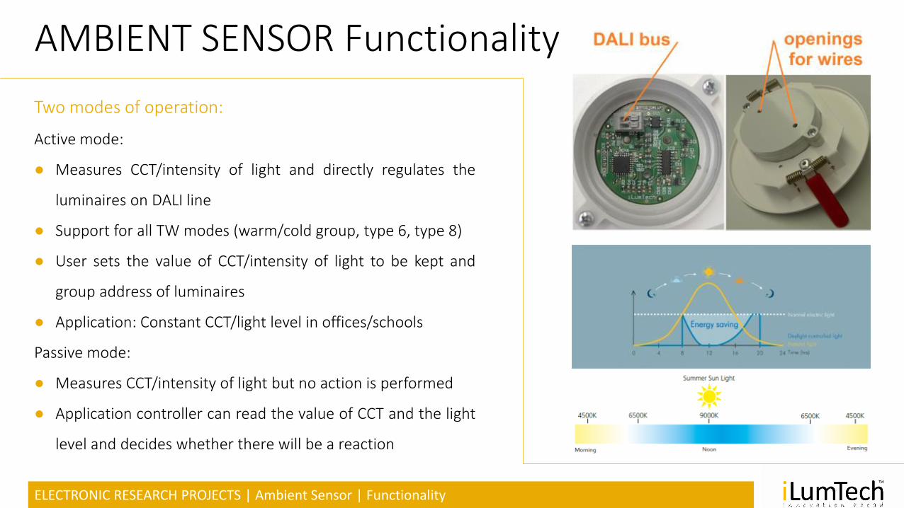
ELECTRONIC RESEARCH PROJECTS | Ambient Sensor | Functionality
AMBIENT SENSOR Functionality
Two modes of operation:
Active mode:
● Measures CCT/intensity of light and directly regulates the
luminaires on DALI line
● Support for all TW modes (warm/cold group, type 6, type 8)
● User sets the value of CCT/intensity of light to be kept and
group address of luminaires
● Application: Constant CCT/light level in offices/schools
Passive mode:
● Measures CCT/intensity of light but no action is performed
● Application controller can read the value of CCT and the light
level and decides whether there will be a reaction

ELECTRONIC RESEARCH PROJECTS | DALI LM Sensor 01
DALI LM Sensor 01
● DALI sensor that measures lux level and detects the movement
● Can directly regulate the luminaires – brightness control
● Movement detection based on PIR
● Max. installation height – 4 m, detection angle 90 °
● Fully configurable via DALI (DALI/USB, DeeBridge, BlueBridge)

ELECTRONIC RESEARCH PROJECTS | DALI PLC Bridge
DALI PLC Bridge
Features:
● DALI PLC Bridge translates DALI commands into PLC and via-versa (IEC
62386-102)
● Allows for coupling DALI network via mains, without using additional wiring
● Powered from DALI, dedicated output for external DALI Power Supply
powering
● Master/Slave topology – single DALI PLC Bridge is Master of network
● Integrated commissioning and network refreshing
● Three-phase support
● Communication error source detection
● Ideal for existing installation, historical buildings or households

ELECTRONIC RESEARCH PROJECTS | DALI PLC Bridge
DALI PLC Bridge

ELECTRONIC RESEARCH PROJECTS | DALI PLC-IN
DALI PLC-IN
Features:
● DALI PLC-IN translates DALI commands into PLC and via-versa (IEC
62386-102)
● Internally powered DALI bus for luminaire control (up to 3 DALI devices)
● Powered from mains, dedicated output for external DALI LED driver or
ballast with integrated filter – power limitation to 100 W
● For higher output power use DALI PLC Separator
● Integrated commissioning and network refreshing
● Ideal for installation inside the luminaire

ELECTRONIC RESEARCH PROJECTS | DALI PLC-IN
DALI PLC-IN

ELECTRONIC RESEARCH PROJECTS | DALI PLC Separator
DALI PLC Separator
Features:
● Filters PLC communication
● Improves the PLC signal strength and performance
● Protect non-PLC devices from PLC communication
● Max. 10 A loading

ELECTRONIC RESEARCH PROJECTS | DALI PLC Separator
DALI PLC Separator

ELECTRONIC RESEARCH PROJECTS | DALI PLC-IN
DALI PLC – how does it work?
● PLC uses 132.5 kHz frequency with BFSK modulation and 4800 Bd rate
● Communication is modulated on mains signal (50 Hz)
● PLC bridges standard DALI communication between the controller and
luminaire in both directions.
● To fulfil timing requirements memory buffer method is used – each PLC
device has buffered information about each DALI device in the network
● Initial mapping triggered by the user – reset button
● Periodical updates

ELECTRONIC RESEARCH PROJECTS | DALI PLC | applications
DALI PLC applications

ELECTRONIC RESEARCH PROJECTS | DALI PLC | applications
DALI PLC applications

ELECTRONIC RESEARCH PROJECTS | DALI PLC | applications
DALI PLC applications

ELECTRONIC RESEARCH PROJECTS | DALI PLC | applications
DALI PLC applications

Thank you for yourattention