Electronic Research, Inc.
34
Structural Standards for Installation, Alteration and Maintenance of Communication Towers, Antennas and Antenna Supporting Structures ANSI/TIA-1019 “DRAFT” Ernie Jones, PE Electronic Research, Inc. Don Doty Stainless, LLC www.stainlessllc.com N A B 2009
Transcript of Electronic Research, Inc.

Structural Standards for Installation, Alteration and Maintenance of Communication Towers, Antennas and Antenna Supporting Structures
ANSI/TIA-1019 “DRAFT”
Ernie Jones, PEElectronic Research, Inc.
Don DotyStainless, LLCwww.stainlessllc.com
N A B2009

History
ASCE 37-02 Design Loads on Structures During ConstructionApproved in 2002
TIA-1019 Gin Pole Standard was approved January 9, 2004.
TIA-222-G Revision of TIA/EIA-222-F Standard for design of communication structures – Aug.
2005
TIA-1019-Construction Standard “Fall of 2009” Includes the Gin Pole Standard

Construction Mishaps

Industry Construction Standard -Benefits to the Tower Owner -
Prevent Accidents Saves Lives
Reduces Liabilities
Reduces Delays in Project Completion
Prevent Undetected Structure Damage
Reduce Construction Costs by Providing Safe Engineering Procedures and Guidelines Without Over-Designing

Tower Erection & Safety
Hire a qualified contractor
Request certificates of all insurance coverage’s
Safety must be required in contract documents
Check references
Ask questions

Three Phases
"in it's simplest form, new towers can be separated into three phases:
Concept
Design
Construction

Guyed Towers
Tall towers require special rigging
Number of available crews
Rigging Plans
Check your policy
Planning is essential
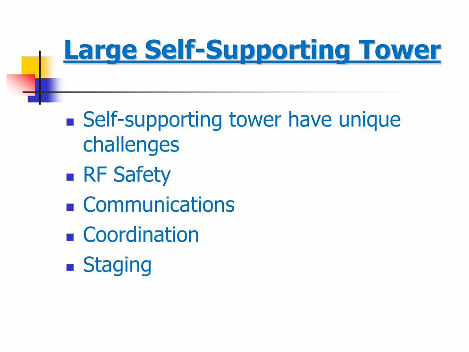
Large Self-Supporting Tower
Self-supporting tower have unique challenges
RF Safety
Communications
Coordination
Staging

Scope and Objective
Consider construction equipment loading effects on a structure being erected or modified. Cranes Gin Poles Lifting Blocks Attached Rigging
Accurate prediction of weather related loading during construction duration period.
Providing an engineered approach to complete work safely throughout the entire construction process.

Table of Contents
1.0 General 2.0 Construction Considerations 3.0 Gin Pole Operation and Use 4.0 Loads on Structure During Construction 5.0 Gin Pole Analysis and Design 6.0 Gin Pole Construction
Annex A Procurement and User Guidelines Annex B Gin Pole Engineering Design Annex C Evaluation of Existing Gin Poles Annex D Rigging Plans Annex E Wire Rope End Connections Annex F Evaluation of a Communication Tower Site Annex G Referenced Standards

Construction Safety & Efficiency Comes from “Proper Preplanning” With Rigging Plans
Class DefinitionsMinimum Level
of
Responsibility
I
Removal or addition of antennas, mounts, platforms,
etc. that are light in comparison to the overall
supporting structure and do not require the use of a gin
pole or a gin pole not rated higher than Class A.
Competent Rigger
IIRigging plans utilizing pre-approved installation
methods.Qualified Person
IIICustom or infrequent installation methods, removal of
structural members, special engineered lifts, and
unique situations
Qualified Person
with Qualified
Engineer
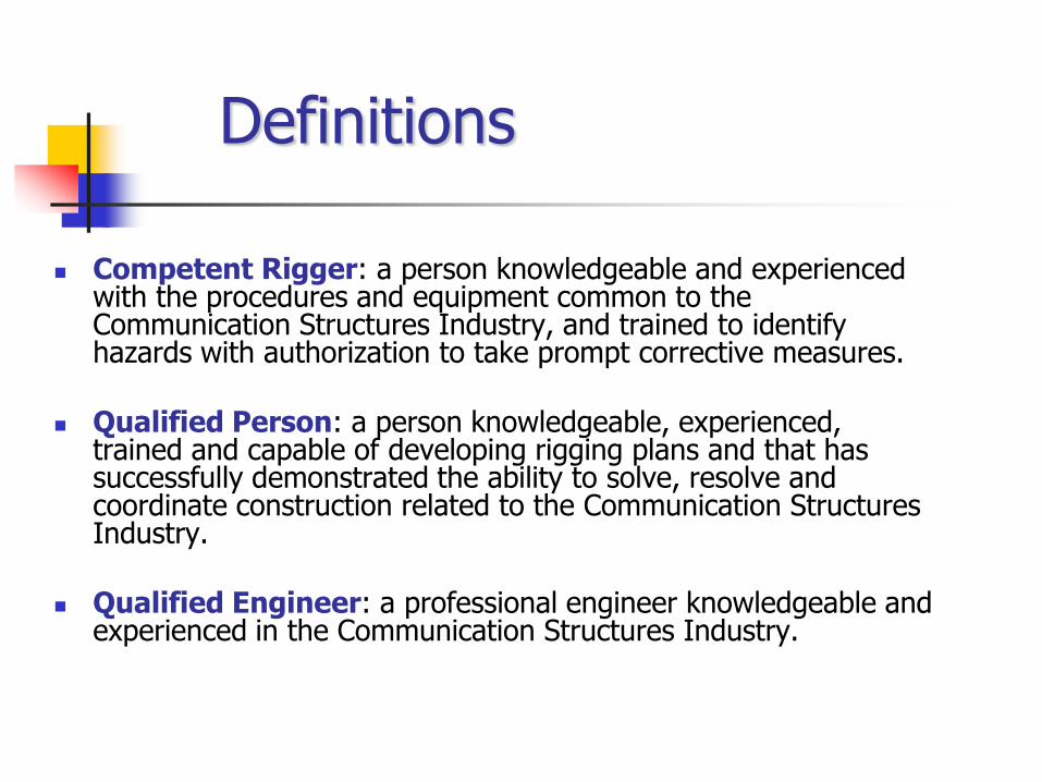
Definitions
Competent Rigger: a person knowledgeable and experienced with the procedures and equipment common to the Communication Structures Industry, and trained to identify hazards with authorization to take prompt corrective measures.
Qualified Person: a person knowledgeable, experienced, trained and capable of developing rigging plans and that has successfully demonstrated the ability to solve, resolve and coordinate construction related to the Communication Structures Industry.
Qualified Engineer: a professional engineer knowledgeable and experienced in the Communication Structures Industry.

Base Rigging
Rigging Plan
Licensed Engineer
WLL
Signage
Barricades
Site Safety

Operational and Non-Operational Conditions
Operational
Loading conditions of a structure during the actual lifting sequence.
Typically governs the strength requirements for lifting devices and their associated rigging.
(gin pole and attached rigging equipment loads)
Non-Operational
Loads on a structure when lifting in not performed.
Typically govern the strength requirements for the structure under construction.
(wind load conditions based on construction duration factor)

Operational and Non-Operational Conditions
“Operational” Condition – During Construction Procedures
A Uniform effective 30 mph 3-sec gust wind speed used during lifts
“Non-Operational” Condition – Weather Related Conditions
Winds from 45 mph to 90 mph based on the construction duration period.
30 mph Wind
45 to 90 mph Wind
Non-Operational
Operational

All lifts within parameters of Gin Pole Charts, or Crane Charts, approved by an Engineer or Equipment Manufacturer

Vertical and Tilted Gin PolesCovered in Standard
Vertical Gin Pole Tilted Gin Pole

Load TestsFor Checking Entire Rigging System
(Operational Conditions)
Load test to 1.5 times the anticipated load.
If slip resistance is counted on for restraint a load test is required.
Required for hoist if anchor calculations arenot possible, or reliable.
Hoist
Load Test Weight

Lifting Existing Loads from Structures
Weight verification necessary for load testing. Use of a load measuring device Unless the load weight is confirmed by accurate
documentation or by calculation, the weight shall be field verified prior to making the lift.
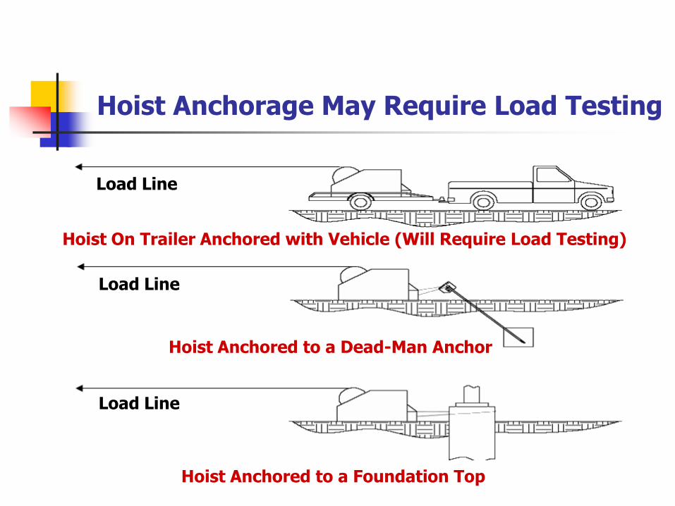
Hoist Anchorage May Require Load Testing
Hoist On Trailer Anchored with Vehicle (Will Require Load Testing)
Hoist Anchored to a Dead-Man Anchor
Hoist Anchored to a Foundation Top
Load Line
Load Line
Load Line
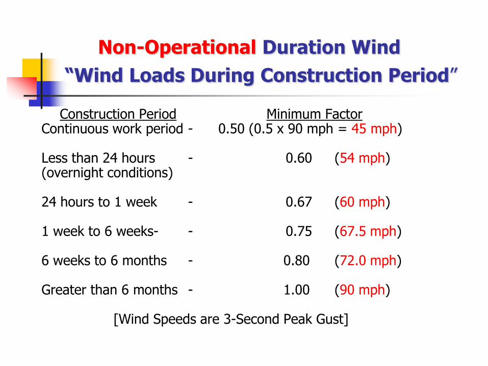
Non-Operational Duration Wind
“Wind Loads During Construction Period”
Construction Period Minimum FactorContinuous work period - 0.50 (0.5 x 90 mph = 45 mph)
Less than 24 hours - 0.60 (54 mph)(overnight conditions)
24 hours to 1 week - 0.67 (60 mph)
1 week to 6 weeks- - 0.75 (67.5 mph)
6 weeks to 6 months - 0.80 (72.0 mph)
Greater than 6 months - 1.00 (90 mph)
[Wind Speeds are 3-Second Peak Gust]

Guy Slippage Parameters Provided
Unequal forces on the structure shall be considered due the potential of connection slippage!
Can the structure withstand the unequal load?
Temporary guy wires may be required
Slippage Im = 1.3
Release Im = 2.0
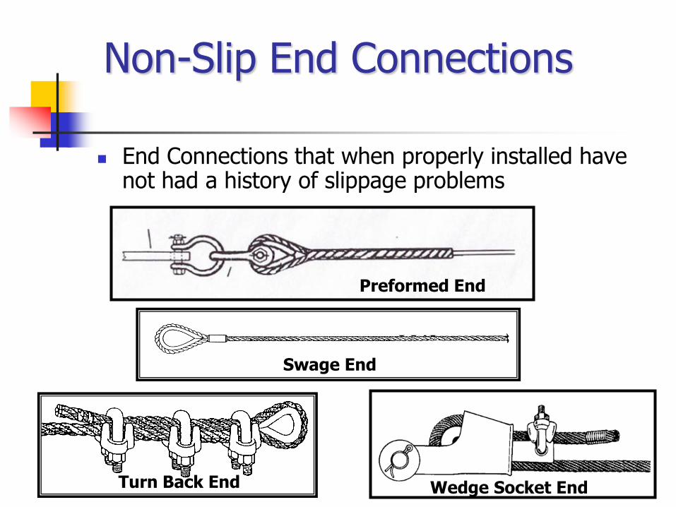
Non-Slip End Connections
End Connections that when properly installed have not had a history of slippage problems
Preformed End
Swage End
Turn Back End Wedge Socket End

Slippage Connections Defined
When frictional clamping devices are used that may slipduring construction, the forces on the structure due to potential effects from slippage or cable release must be considered.
The structure shall be analyzed for this potential slippage.

Temporary Backup System The backup system shall be of non-slip wire rope termination
arranged to limit slippage to ½ face width of tower, but not less than 12 inches or more than 36 inches.
Chicago Grip
Attached Preform
Tension MeterCome-Along
Turnbuckle to be Attached
Cable Clamped Backup
Guy Anchor
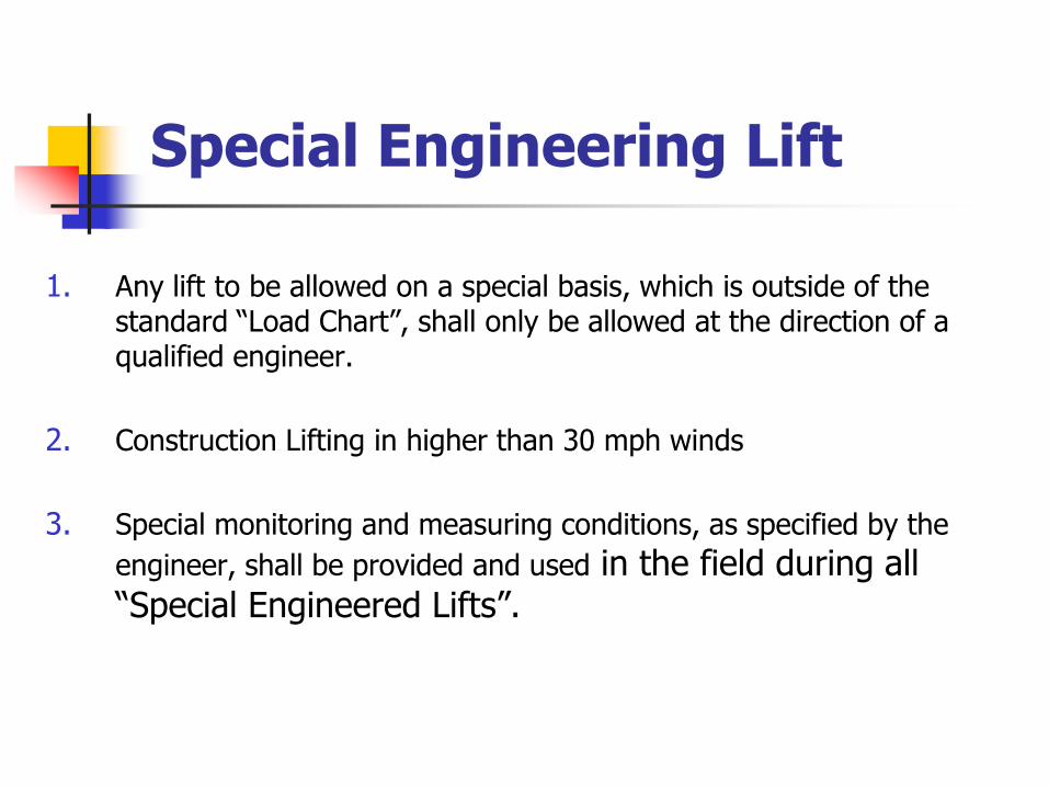
Special Engineering Lift
1. Any lift to be allowed on a special basis, which is outside of the standard “Load Chart”, shall only be allowed at the direction of a qualified engineer.
2. Construction Lifting in higher than 30 mph winds
3. Special monitoring and measuring conditions, as specified by the
engineer, shall be provided and used in the field during all “Special Engineered Lifts”.

Monitoring Gin Pole Tip Deflection During a Lift
“Thru a Transit”

Capstan Hoist & Use of Synthetic Rope
Factor of Safety for Rope at 10 to 1. (to account for knots)
The lifted load shall not exceed the hoist rated capacity. 1.5 times lift weight load test required – this will usually
limit loads lifted with capstans to 600 lbs. or less!

Top BlockLocate Top Block at Panel Point
Load Test at 600 Lbs
Test Wt.
Hand Tag Line Capstan on Truck
Capstan Load Test: Requires Load Test of 150% of Lifted Load

What Owners Need To Know!
1. This industry construction standard will be available in the near future.
2. It will be a basis to allow construction workers and engineers provide safe construction procedures without being overly conservative due to the lack of readily available, or properly understood, guidelines.
3. In the event it is required for construction projects it should lessen the liabilities of all parties participating in its proper use.
4. When properly used it will prevent future construction accidents and structure collapses!
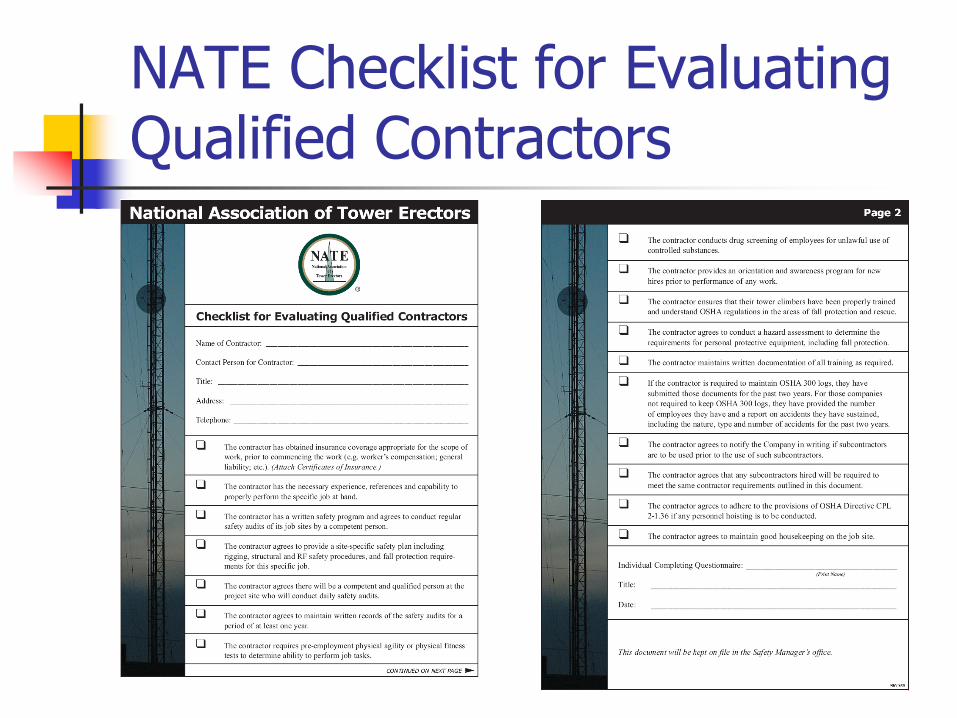
NATE Checklist for Evaluating Qualified Contractors

Contractor Qualifications, RFP, Comparison Form
Hire a qualified contractor
Check their references
Certificate of insurance
Rigging Plan

MULTI-EMPLOYER ISSUES
• Potential civil and criminal liability
• Amendments currently being aggressively pursued in Washington will enhance criminality (for amputations, disfiguring injuries , permanent loss of brain function) as well as to make a conviction go from:
•Current:
•6 mos imprisonment
•Fine of $500K against the employer
•Fine of $25K against the manager
•To a felony
•Minimum of one year imprisonment
•No limitations on the fines

T I A Standards & Technology Department2500 Wilson Boulevard, Suite 300Arlington, VA 22201 USA1-703-907-7700
Global Engineering Documents15 Inverness Way EastEnglewood, CO 80112-57041-800-854-7179
Thank You!