Electromagnetic Induction Chapter 31 (cont.) Faraday’s Law & Lenz’s Law Induced Electric Fields...
31
Electromagnetic Electromagnetic Induction Induction Chapter 31 Chapter 31 (cont.) (cont.) Faraday’s Law & Lenz’s Faraday’s Law & Lenz’s Law Law Induced Electric Induced Electric Fields Fields Mutual Inductance Mutual Inductance Self-Inductance Self-Inductance Inductors in Circuits Inductors in Circuits Magnetic Energy Magnetic Energy
-
Upload
phyllis-clarke -
Category
Documents
-
view
240 -
download
2
Transcript of Electromagnetic Induction Chapter 31 (cont.) Faraday’s Law & Lenz’s Law Induced Electric Fields...
Electromagnetic InductionElectromagnetic Induction
Chapter 31Chapter 31(cont.)(cont.)
Faraday’s Law & Lenz’s LawFaraday’s Law & Lenz’s LawInduced ElectricInduced Electric FieldsFields
Mutual InductanceMutual InductanceSelf-InductanceSelf-Inductance
Inductors in CircuitsInductors in CircuitsMagnetic EnergyMagnetic Energy

Electromagnetic InductionFaraday’s Law
A changing magnetic field induces an emfproportional to the rate of change of magnetic flux:
= - dB / dt
The emf is about some loop – and the flux is through that loop.
€
B =r B ⋅d
r A ∫ = Bcosθ dA∫
Lenz’s law: the induced emf is directed so that any induced current opposes the change in magnetic flux that causes the
induced emf.

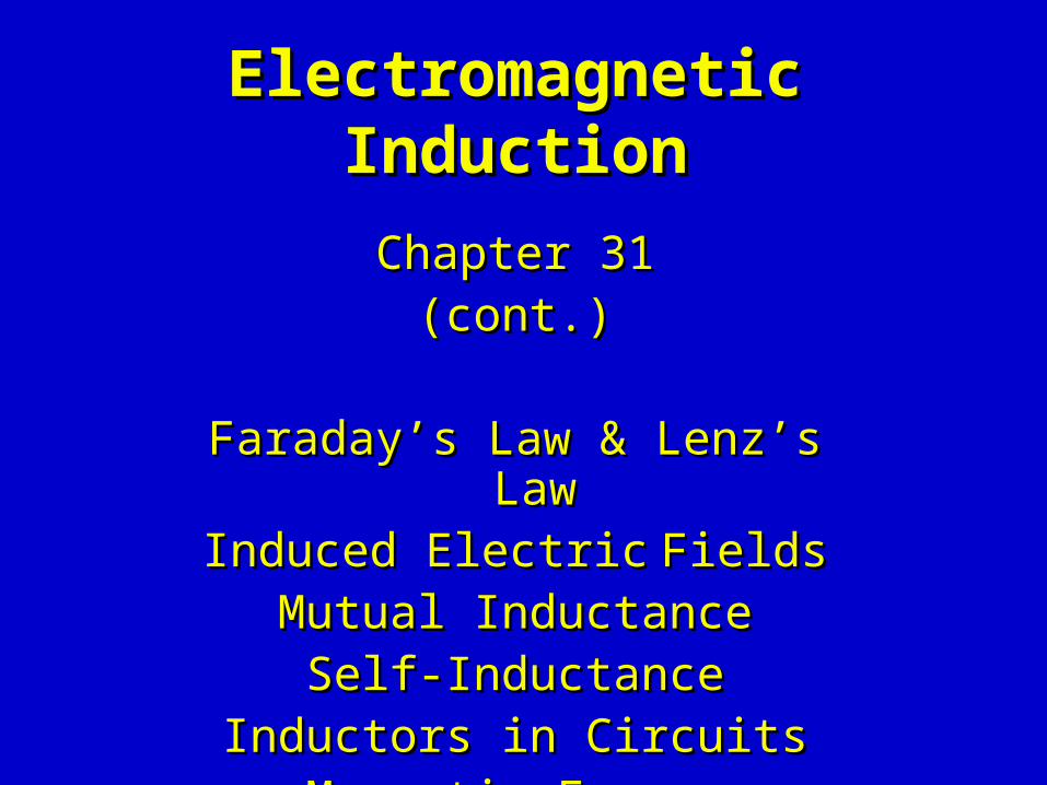
Rotating Loop - The Electric Generator
Consider a loop of area A in a uniform magnetic field B.Rotate the loop with an angular frequency .
A
B
The flux changes because angle changes with time: = t. Hence
dB/dt = d(B · A)/dt
= d(BA cos )/dt
= BA d(cos(t))/dt
= - BA sin(t)
A
• Then by Faraday’s Law this motion causes an emf
= - dB /dt = BA sin(t)
• This is an AC (alternating current) generator.
BA
dB/dt = - BA sin(t)
Rotating Loop - The Electric Generator

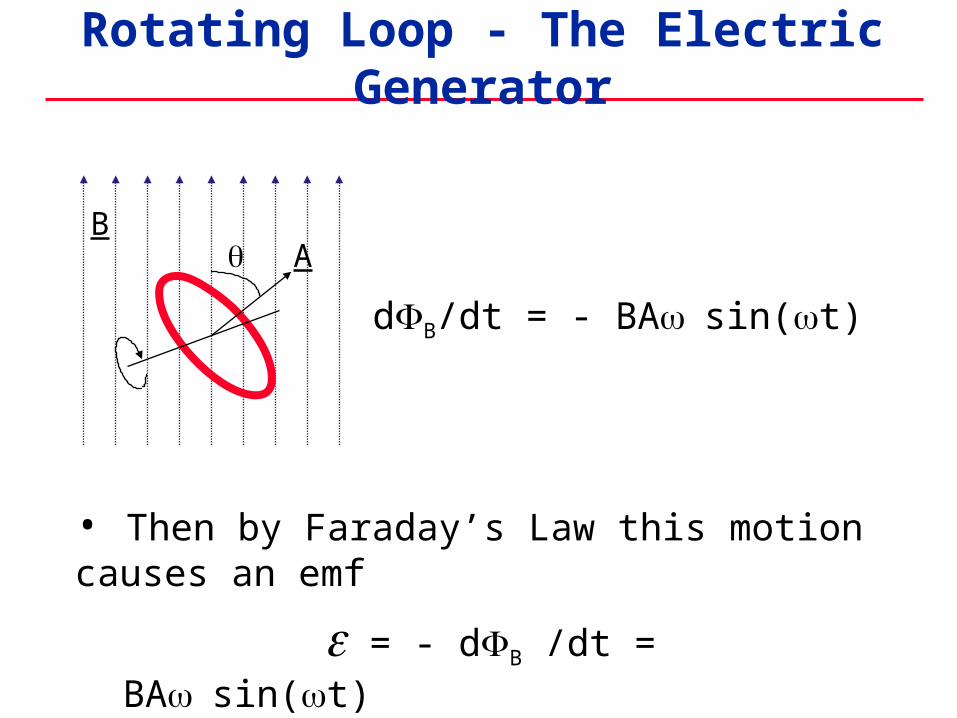
Consider a stationary wire in a time-varying magnetic field. A current starts to flow.
Induced Electric Fields
x dB/dt
So the electrons must feel a force F.
It is not F = qvxB, because the charges started stationary.Instead it must be the force F=qE due to an
induced electric field E.
That is:A time-varying magnetic field B
causes an electric field E to appear!

Consider a stationary wire in a time-varying magnetic field. A current starts to flow.
Induced Electric Fields
x dB/dt
So the electrons must feel a force F.
It is not F = qvxB, because the charges started stationary.Instead it must be the force F=qE due to an
induced electric field E.
Moreover E around the loop gives a voltage diff V=E·dl.And this must be the emf:
= E·dlo
Induced Electric Fields
E·dl = - dB/dto
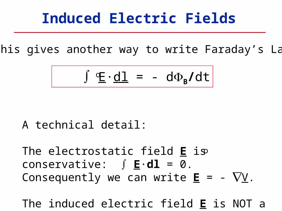
This gives another way to write Faraday’s Law:
A technical detail:
The electrostatic field E is conservative: E·dl = 0.Consequently we can write E = - V.
The induced electric field E is NOT a conservative field.We can NOT write E = -V for an induced field.
o

Electrostatic Field Induced Electric Field
F = q E F = q E
Vab = - E·dl
E·dl = 0 and Ee = V
E · dl = - dB/dt
E·dl 0
Conservative Nonconservative
Work or energy difference does NOT depend on path
Work or energy difference DOES depend on path
Caused by stationarycharges
Caused by changingmagnetic fields
o
o
o
Induced Electric Fields
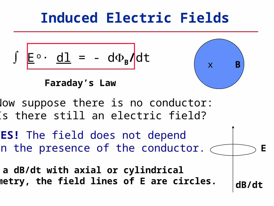
x B E · dl = - dB/dto
Faraday’s Law
Now suppose there is no conductor:Is there still an electric field?
YES! The field does not depend on the presence of the conductor.
For a dB/dt with axial or cylindrical symmetry, the field lines of E are circles. dB/dt
E
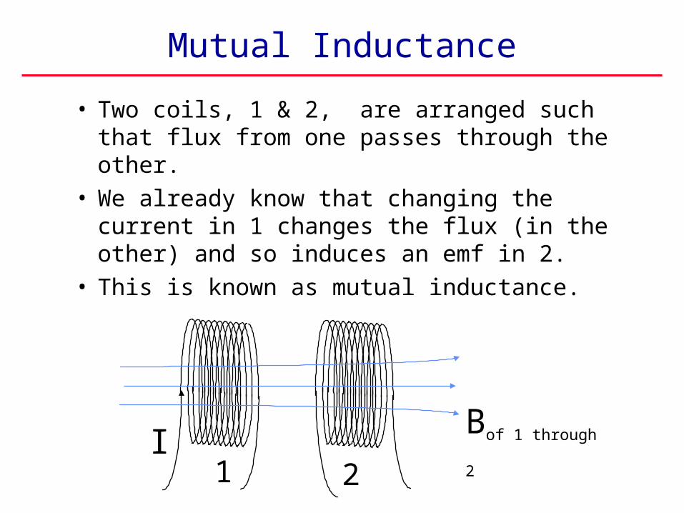
Mutual Inductance
• Two coils, 1 & 2, are arranged such that flux from one passes through the other.
• We already know that changing the current in 1 changes the flux (in the other) and so induces an emf in 2.
• This is known as mutual inductance.
IBof 1 through 2
1 2

Mutual Inductance
The mutual inductance M is the proportionality constant between 2 and I1:
2 = M I1
so d2 /dt = M dI1 /dtThen by Faraday’s law:
2= - d2 /dt = - M dI1 /dt
Hence M is also the proportionality constant
between 2 and dI1 /dt.
Bof 1 through 2I
1 2

Mutual Inductance
• M arises from the way flux from one coil passes through the other: that is from the geometry and arrangement of the coils.
• Mutual means mutual. Note there is no subscript on M: the effect of 2 on 1 is identical to the effect of 1 on 2.
• The unit of inductance is the Henry (H).
1 H = 1Weber/Amp = 1 V-s/A

• If the current is steady, the coil acts like an ordinary piece of wire.
• But if the current changes, B changes and so then does , and Faraday tells us there will be an induced emf.
• Lenz’s law tells us that the induced emf must be in such a direction as to produce a current which makes a magnetic field opposing the change.
Self Inductance
I B
A changing current in acoil can induce an emfin itself….
Self Inductance
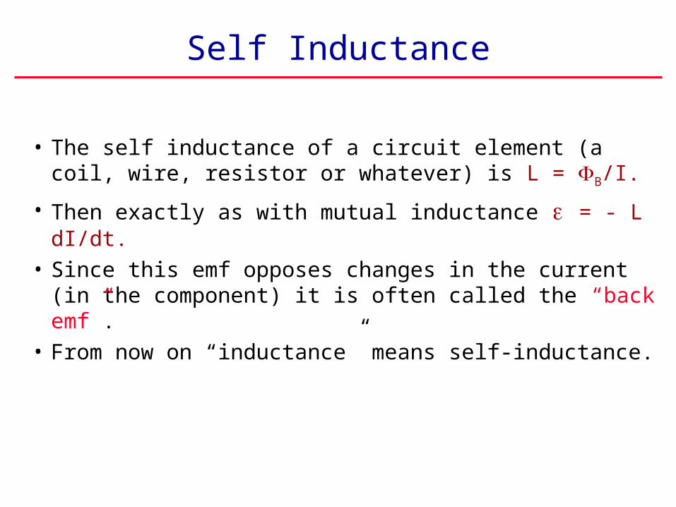
• The self inductance of a circuit element (a coil, wire, resistor or whatever) is L = B/I.
• Then exactly as with mutual inductance = - L dI/dt.
• Since this emf opposes changes in the current (in the component) it is often called the “back emf”.
• From now on “inductance” means self-inductance.

L = 0n2Ad
What is the (self) inductance of a solenoid with area A, length d, and n turns per unit length?
In the solenoid B = 0nI, so the flux through one turn
is B = BA = 0nIA
The total flux in the solenoid is (nd)B
Therefore, B = 0n2IAd and so L = B/I gives
Example: Finding Inductance
(only geometry)
Inductance Affects Circuits and Stores Energy
• This has important implications…..• First an observation: Since cannot be
infinite neither can dI/dt. Therefore, current cannot change instantaneously.
• We will see that inductance in a circuit affects current in somewhat the same way that capacitance in a circuit affects voltage.
• A ‘thing’ (a component) with inductance in a circuit is called an inductor.
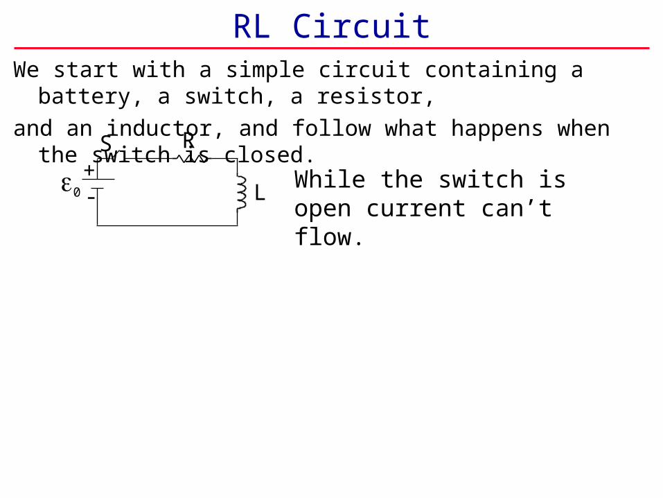
RL Circuit
R
LWhile the switch is open current can’t flow.
We start with a simple circuit containing a battery, a switch, a resistor,
and an inductor, and follow what happens when the switch is closed.
+-
S
0

RL Circuit
R
L
L
When the switch is closed current I flows, growing gradually, and a
‘back emf’ L=- L dI/dt is generated in the inductor. This opposes the current I.
While the switch is open current can’t flow.
We start with a simple circuit containing a battery, a switch, a resistor,
and an inductor, and follow what happens when the switch is closed.
+-
S
I0
+-
S
0

RL Circuit
R
L
L
After a long time the current
becomes steady. Then L is zero.
When the switch is closed current I flows, growing gradually, and a
‘back emf’ L=- L dI/dt is generated in the inductor. This opposes the current I.
While the switch is open current can’t flow.
We start with a simple circuit containing a battery, a switch, a resistor,
and an inductor, and follow what happens when the switch is closed.
0Is
+-
S
I0
+-
S
0
+-
S
0

RL Circuit
0/R
I
00 1 2 3 4 5
t/(L/R)
the current I increases exponentially from I = 0 to I = 0/R
When the switch S is closed
+-
S
I0
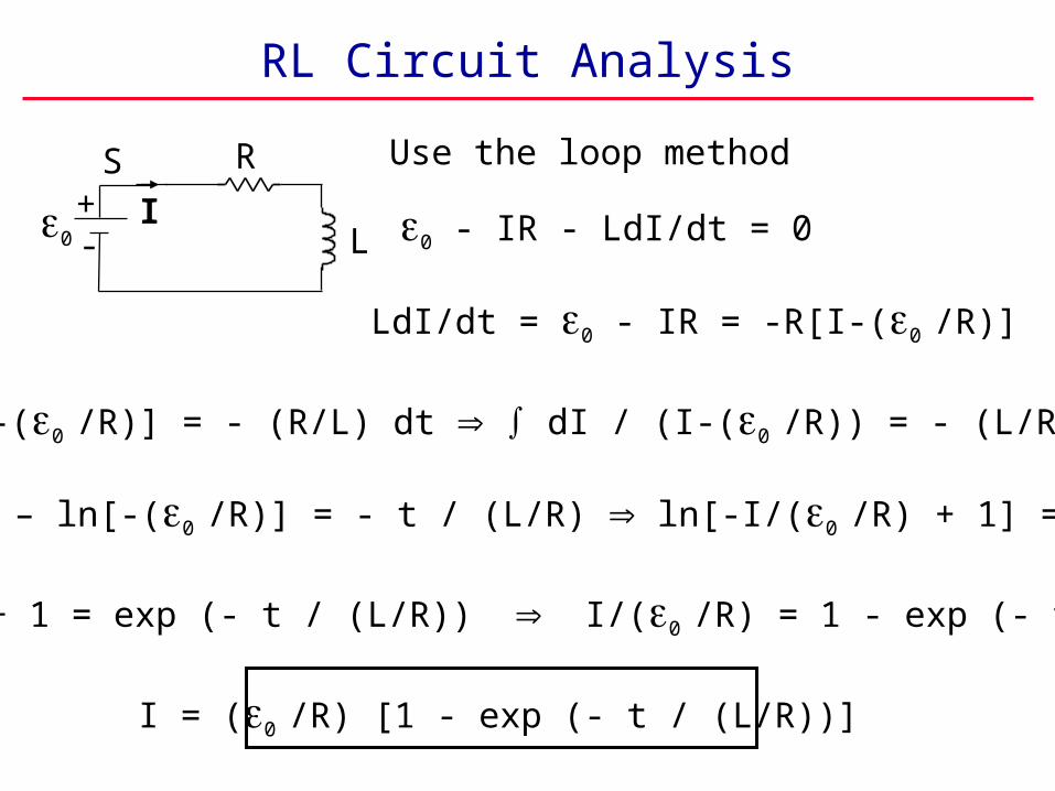
RL Circuit Analysis
Use the loop method
0 - IR - LdI/dt = 0
LdI/dt = 0 - IR = -R[I-(0 /R)]
dI / [I-(0 /R)] = - (R/L) dt dI / (I-(0 /R)) = - (L/R) dt
ln[I-(0 /R)] – ln[-(0 /R)] = - t / (L/R) ln[-I/(0 /R) + 1] = - t / (L/R)
-I/(0 /R) + 1 = exp (- t / (L/R)) I/(0 /R) = 1 - exp (- t / (L/R))
I = (0 /R) [1 - exp (- t / (L/R))]
R+-
S
I0 L

RC Circuit Analysis
0 /R
I
00 1 2 3 4 5
t/(L/R)
I = (0/R) [1 - exp (- t / (L/R))]
The current increasesexponentially
with time constant = L / R
t = 0 I = 0
t = I = 0 /R
R+-
S
I0 L

Inductor’s emf L
L
0
0 1 2 3 4 5
t/(L/R)
-0
L = - L (dI/dt)
I = (0/R) [1 - exp (- t / (L/R))]
L = L (0/R) (-R/L) exp (- t / (L/R))
L = - 0 exp (- t / (L/R))
t = 0 L = - 0
t = L = 0
R+-
S
I0 L

Decay of an RL Circuit
• After I reaches 0/R move the switch as shown.
• The loop method gives L - IR = 0 or L = IR
• Remember that L = -L dI/dt -L dI/dt = IR
dI/I = - dt / (L/R) dI/I = - dt / (L/R)• ln I/I0 = - t / (L/R) I = I0 exp [- t / (L/R)]
• But I0 = 0/R
• Then: I = (0/R) exp [- t / (L/R)]
R+-
S
0 L

Inductors in Circuits
• The presence of inductance prevents currents from changing instantaneously.
• The time constant of an RL circuit is = L/R.
• When the current is not flowing the inductor tries to keep it from flowing. When the current is flowing the inductor tries to keep it going.
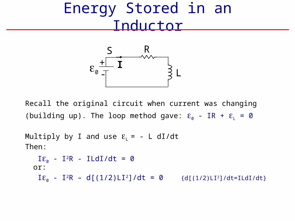
Energy Stored in an Inductor
Recall the original circuit when current was changing
(building up). The loop method gave: 0 - IR + L = 0
Multiply by I and use L = - L dI/dt
Then:
I0 - I2R - ILdI/dt = 0or:
I0 - I2R – d[(1/2)LI2]/dt = 0 {d[(1/2)LI2]/dt=ILdI/dt}
R+-
S
I0 L
• Think about I0 - I2R - d((1/2)LI2)/dt = 0
• I0 is the power (energy per unit time) delivered by the battery.
• I2R is the power dissipated in the resistor.

• Think about I0 - I2R - d((1/2)LI2)/dt = 0
• I0 is the power (energy per unit time) delivered by the battery.
• I2R is the power dissipated in the resistor.• Hence we’d like to interpret d((1/2)LI2)/dt as the rate at
which energy is stored in the inductor.In creating the magnetic field in the inductor
we are storing energy

UB = (1/2) LI2
• Think about I0 - I2R - d((1/2)LI2)/dt = 0
• I0 is the power (energy per unit time) delivered by the battery.
• I2R is the power dissipated in the resistor.• Hence, we’d like to interpret d[(1/2)LI2]/dt as the rate
at which energy is stored in the inductor.In creating the magnetic field in the inductor
we are storing energy• The amount of energy in the magnetic field is:

Energy Density in a Magnetic Field
• We have shown
• Apply this to a solenoid:
• Dividing by the volume of the solenoid, the stored energy density is:
• This turns out to be the
energy density in a magnetic field
€
UB = 1
2LI2
uB = B2/(20)
€
UB = 1
2μon
2Al I2 =Al
2μo
μo2n2I2
( ) =Al
2μo
B2

Summary
• We defined mutual and self inductance,• Calculated the inductance of a solenoid.• Saw the effect of inductance in RL circuits.• Developed an expression for the stored energy.• Derived an expression for the energy density of a
magnetic field.• Next class we will start learning about alternating-
current (AC) circuits, containing resistors, capacitors, and inductors.