Electromagnetic Induction (Chapters...
22
Electromagnetic Induction (Chapters 31-32) • The laws of emf induction: Faraday’s and Lenz’s laws • Inductance • Mutual inductance M • Self inductance L. Inductors • Magnetic field energy • Simple inductive circuits • RL circuits • LC circuits • LRC circuits
Transcript of Electromagnetic Induction (Chapters...

Electromagnetic Induction
(Chapters 31-32)
• The laws of emf induction: Faraday’s and Lenz’s laws
• Inductance
• Mutual inductance M
• Self inductance L. Inductors
• Magnetic field energy
• Simple inductive circuits
• RL circuits
• LC circuits
• LRC circuits
• We’ve seen that an electric current produces a magnetic field. Should we presume
that the reverse is valid as well? Can a magnetic field produce an electric current?
• Yes, magnetic fields can produce electric fields through electromagnetic induction
• Most of the electric devices that we use as power supplies are electric generators
based on induced emf : these generators convert different forms of energy first into
mechanical energy and then, by induction, into electric energy
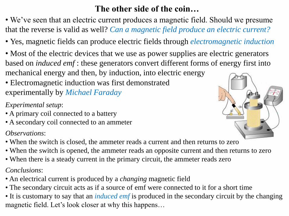
The other side of the coin…
Experimental setup:
•A primary coil connected to a battery
•A secondary coil connected to an ammeter
Observations:
• When the switch is closed, the ammeter reads a current and then returns to zero
• When the switch is opened, the ammeter reads an opposite current and then returns to zero
• When there is a steady current in the primary circuit, the ammeter reads zero
Conclusions:
•An electrical current is produced by a changing magnetic field
• The secondary circuit acts as if a source of emf were connected to it for a short time
• It is customary to say that an induced emf is produced in the secondary circuit by the changing
magnetic field. Let’s look closer at why this happens…
• Electromagnetic induction was first demonstrated
experimentally by Michael Faraday

Gauss’s Law – Electric Flux
Def: The electric flux of a
uniform magnetic field B
crossing a surface A under
an angle θ with respect to
the normal to the surface is
B BA
cosB BA
0B
B B dA
B
Aθ
θ
Ex: The uniform field lines
penetrate an area A perpendicular
and then parallel to the surface,
produce maximum and zero fluxes
B
ˆA An
A
B
• In order to quantify the idea of emf induction, we
must introduce the magnetic flux since the emf is
actually induced by a change in magnetic flux rather
than generically by a change in the magnetic field
• Magnetic flux is defined in a manner similar to that
of electrical flux:
2
SIT m Weber WbB
If the field varies across the surface, one must
integrate the contribution to the flux for every
element of surface:
Exercise 1: Gauss’s law can be
reformulated for magnetic sources.
Try to do it yourself: what is the
magnetic flux through a closed
surface around a magnetic source?

Quiz:
1. Given a solenoid, through which of the shown surfaces is the
magnetic flux larger?
A1 A2 A3 A4
2. A long, straight wire carrying a current I is placed along the axis of a cylindrical surface of
radius r and a length L. What is the total magnetic flux through the cylinder?
A1
A2
A3
A4
I
r
Ia)
b)
c) Zero
0ILL
0
2
IL
r

Electromagnetic Induction – Faraday’s Law and Lenz’s Law
Faraday’s Law: The instantaneous emf induced in a circuit equals
the time rate of change of magnetic flux ΦB through the circuit
• The involvement of magnetic flux in the electromagnetic induction is described
explicitly by
Bd
dt
Comments:
• Since ΦB = BAcosθ the change in the flux, dΦB, can be produced by a change in B,
A or/and θ
• If the circuit contains N loops (such as a coil with N turns)
• The negative sign in Faraday’s Law is included to indicate the polarity of the
induced emf, which is more easily found using:
Lenz’s Law: The direction of any magnetic induction effect is to oppose the cause
of the respective effect
Ex: Causes of EM induction can be: varying magnetic fields, currents, emfs, or forces
determining a change in flux for instance by varying the area exposed to the magnetic field.
Induced effects may be magnetic fields, emfs, currents, forces, electric fields
BN d dt

Magnetic flux through a loop can be varied by moving a bar
magnet in proximity
1. If the bar magnet is moved toward a loop of wire:
• As the magnet moves, the magnetic flux increases with time
• The induced current will produce a magnetic field opposing
the increasing flux, so the current is in the direction shown
• This can be seen as a repelling effect onto the incoming bar by
the loop seen as a magnet
2. If the bar magnet is moved away from a loop of wire:
• As the magnet moves, the magnetic flux decreases with time
• The induced current will produce a magnetic field helping the
decreasing flux, so the current is in the direction shown
• This can be seen as a attraction effect onto the bar by the loop
seen as a magnet
Electromagnetic Induction – Applying Lenz’s Law
Bind
Bind
repels the
incoming North
attracts the
departing North
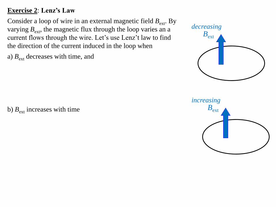
Exercise 2: Lenz’s Law
Consider a loop of wire in an external magnetic field Bext. By
varying Bext, the magnetic flux through the loop varies an a
current flows through the wire. Let’s use Lenz’t law to find
the direction of the current induced in the loop when
a) Bext decreases with time, and
b) Bext increases with time
Bext
Bext
decreasing
increasing

Exercises:
3. Emf induced by moving field: A bar magnet is
positioned near a coil of wire as shown in the figure.
What is the direction of the induced magnetic field in the
coil and the induced current through the resistor when
the magnet is moved in each of the following directions.
a) to the right
b) to the left
4. Emf induced by switching field on and off: Find the
direction of the current in the resistor in the figure at
each of the following times.
a) at the instant the switch is closed
b) after the switch has been closed for several minutes
c) at the instant the switch is opened
Problem:
1. Emf induced by reversing field: A wire loop of radius r lies so that an external magnetic
field B1 is perpendicular to the loop. The field reverses its direction, and its magnitude
changes to B2 in a time Δt. Find the magnitude of the average induced emf in the loop during
this time in terms of given quantities.
vb
va

abV EL FL q vBL
• We’ve seen that, in certain conditions, motion can determine an
emf – we are interested in this phenomenon since it stays behind
converting mechanical energy into electric energy
• To see how it happens, consider a straight conductor of length
L moving with constant velocity v perpendicular on a uniform
field B: the electric carriers in the conductor experience a
magnetic force qvB along the conductor, as on the figure
• Notice that the electrons tend to move to the lower end of the
conductor, such that a negative charge accumulate at the base
• Consequently, a positive charge forms at the upper end of the conductor, such that,
as a result of this charge separation, an electric field E is produced in the conductor
• Charges build up at the ends of the conductor until the upward magnetic force (on
positive carriers forming a current) is balanced by the downward electric force qE
Motional emf – Across a conductor moving in a magnetic field
• The potential difference between the ends of the
conductor is similar with the potential difference
between the plates of a charged capacitor:
• This motional emf is maintained across the conductor as long as there is motion
Ex: The magnetic field of Earth is
about 5×10⁻⁵ T. Therefore, if a
straight 1-m metallic rod is moved
perpendicular on the field with a
speed of 1 m/s, the emf produced
across it ends is about 5×10⁻⁵ V
+
mF qvB
eF qE
+
–
v
B
Lq
a
b

• Consider now that the moving bar on the previous
slide has a negligible resistance and it slides on rails
connected in a circuit to a resistor R, as in the figure
• As the bar is pulled to the right with a velocity v by
an applied force, the free charges move along the
length of the bar producing a potential difference and
consequently an induced current through R
• The motional emf induced in the circuit acts like a
battery with an emf
• In general, for any conductor moving with velocity
v in a magnetic field B we have an alternative
expression for Faraday’s law:
vBL RI I vBL R
v B dl vBL
force per unit charge (i.e., field) acted
on the element dl of conductor moving
in the external magnetic field B
Motional emf – Producing current in a circuit
The integral is
around a closed
conductor loop
+
+
R
+
–
Lv
B
I
I
The charge carriers are
pushed upward by the
magnetic force
R
I
I
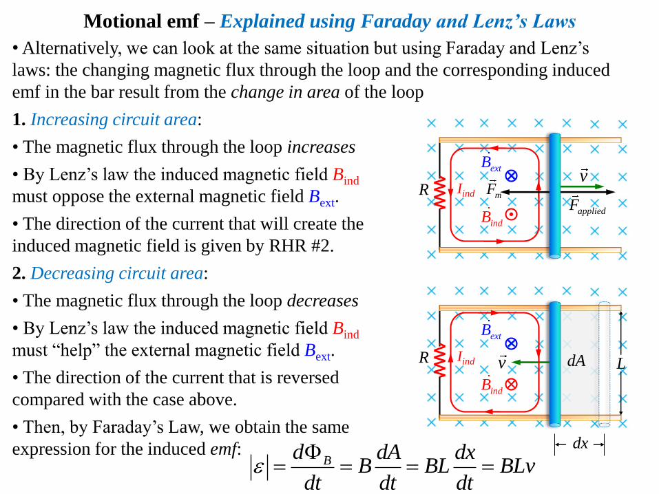
Motional emf – Explained using Faraday and Lenz’s Laws
•Alternatively, we can look at the same situation but using Faraday and Lenz’s
laws: the changing magnetic flux through the loop and the corresponding induced
emf in the bar result from the change in area of the loop
1. Increasing circuit area:
• The magnetic flux through the loop increases
• By Lenz’s law the induced magnetic field Bind
must oppose the external magnetic field Bext.
• The direction of the current that will create the
induced magnetic field is given by RHR #2.
2. Decreasing circuit area:
• The magnetic flux through the loop decreases
• By Lenz’s law the induced magnetic field Bind
must “help” the external magnetic field Bext.
• The direction of the current that is reversed
compared with the case above.
• Then, by Faraday’s Law, we obtain the same
expression for the induced emf:Bd dA dx
B BL BLvdt dt dt
Rv
Iind
extB
indB
mF
R LvIind
extB
indB
dA
dx
appliedF

m
l
R
B
Problems:
2. Gravity as applied force to induce emf: A metallic rod of mass
m slides vertically downward along two rails separated by a distance
ℓ connected by a resistor R. The system is immersed in a constant
magnetic field B oriented into the page.
a) Calculate the current flowing through the resistor R when the
magnetic force on the rod becomes equal to its weight.
b) Calculate the emf induced across the resistor R.
c) Use Faraday’s Law to compute the speed of the rod when the net
force on it is zero.
3. Faraday disk: A thin conducting disk with radius R laying in xy-plane rotates with
constant angular velocity ω around z-axis in a uniform magnetic field B parallel with z. Find
the induced emf between the center and the rim of the disk.

max sin sinBA t t
B
θ
v
I
r
Applications – Electric Generators
•An alternating Current (ac) generator converts mechanical energy to electrical
energy by rotating loops of wire in magnetic fields
• There is a variety of sources that can supply the energy to rotate the loop, including
falling water, heat by burning coal or nuclear reactions, etc.
Basic operation of the generator: as the loop
rotates, the magnetic flux through its surface A
changes with time, such that an emf is induced
• For constant angular speed ω = dθ/dt,
Bθ = ωt
ω
r
v
v
cos sinBd d dBA BA
dt dt dt
Comments:
• The emf polarity varies sinusoidally (ac signal)
• ε = εmax when loop is parallel to the field
• ε = 0 when the loop is perpendicular to the field
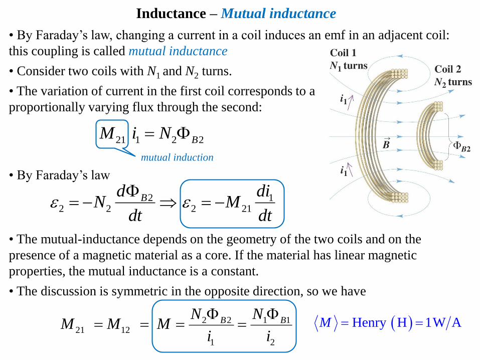
• Consider two coils with N1 and N2 turns.
• The variation of current in the first coil corresponds to a
proportionally varying flux through the second:
• By Faraday’s law
22 2
BdN
dt
• By Faraday’s law, changing a current in a coil induces an emf in an adjacent coil:
this coupling is called mutual inductance
21 1 2 2 BM i N
mutual induction
12 21
diM
dt
• The mutual-inductance depends on the geometry of the two coils and on the
presence of a magnetic material as a core. If the material has linear magnetic
properties, the mutual inductance is a constant.
• The discussion is symmetric in the opposite direction, so we have
2 2 1 121 12
1 2
B BN NM M M
i i
Henry H 1W AM
Inductance – Mutual inductance

Inductance – Self inductance
• L is a proportionality constant called the inductance of the coil:
• Notice that nothing prevents a changing flux to produce an emf in the very coil that
produces the actual flux: this phenomenon is called self-inductance: discovered in
the 19th century by Joseph Henry
Ex: Consider a current carrying loop of wire
• If the current increases in a loop, the magnetic flux through the loop surface due to this
current also increases: hence, an emf is induced that opposes the change in magnetic flux
• This opposing emf results in a slowed down increase of the current through the loop
• Alternatively, if the current decreases, the self-inductance will slow down the rate of decrease
diL
dt
negative sign indicates
that a changing current
induces an emf in
opposition to that change
• The self-induced emf is proportional to the
rate of change of the current through the coil:
BL NI
SIHenry (H)L
Def: If a circuit with N loops carrying a current I produces a magnetic flux ΦB
through each loop surface, the self-inductance is given by
εback<0 εback>0
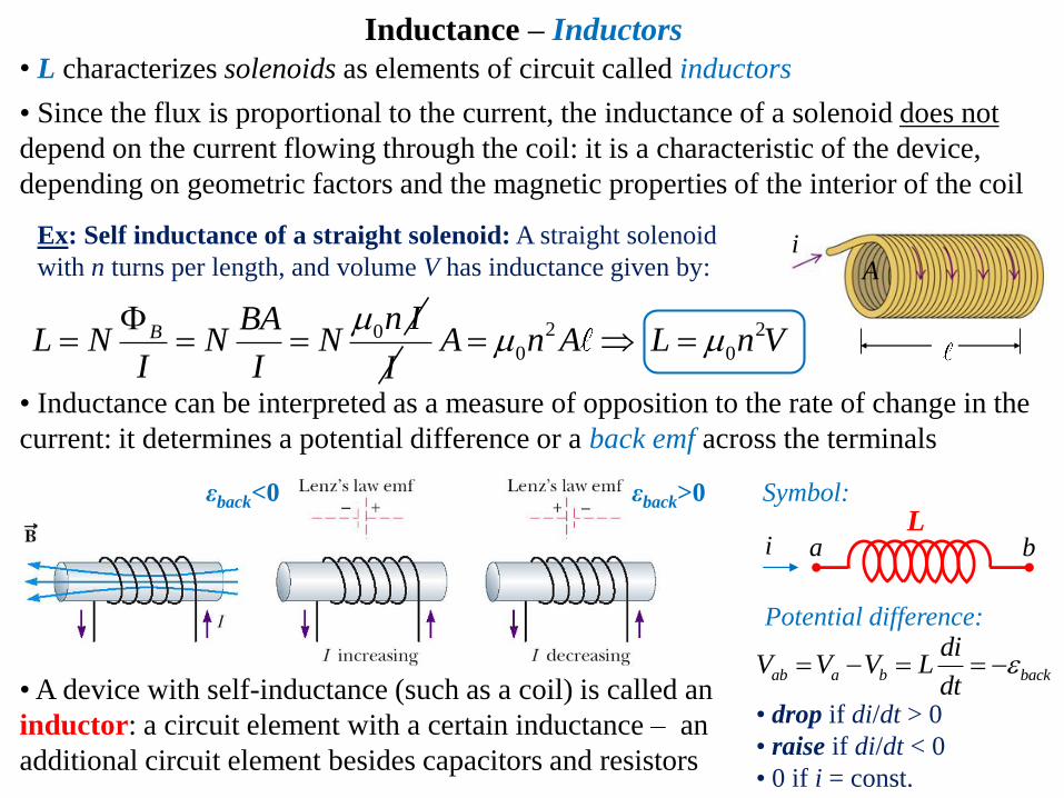
• L characterizes solenoids as elements of circuit called inductors
• Since the flux is proportional to the current, the inductance of a solenoid does not
depend on the current flowing through the coil: it is a characteristic of the device,
depending on geometric factors and the magnetic properties of the interior of the coil
• A device with self-inductance (such as a coil) is called an
inductor: a circuit element with a certain inductance – an
additional circuit element besides capacitors and resistors
Inductance – Inductors
Li a b
Symbol:
Potential difference:
ab a b back
diV V V L
dt
• drop if di/dt > 0
• raise if di/dt < 0
• 0 if i = const.
• Inductance can be interpreted as a measure of opposition to the rate of change in the
current: it determines a potential difference or a back emf across the terminals
Ex: Self inductance of a straight solenoid: A straight solenoid
with n turns per length, and volume V has inductance given by:
0Bn IBA
L N N NI I
I
2 2
0 0 A n A L n V
iA

Energy Stored in a Magnetic Field – Summary of circuit elements
• The work done by a battery to produce an
increasing current against the back emf of an
inductor can be thought of as energy stored
in the magnetic field inside the inductor
• Contrast with the energy dissipated across a current carrying resistor:
• Or the energy stored in the electric field of a charged capacitor:
212LU IL
212RP RI
212CU CV
2
0L n A
R A
0C A d
A
A
d
A
L Ldi
Vdt
RV IR
CVC
Q
0
I
L abU Pdt iV dt L idi
• The magnetic energy density stored in a straight solenoid inductor is given by221
02 1
2
V
V V
LnLIU
u
2
V
I
22
0
0 0
1
2 2
BnI
this is, in general,
the magnetic energy
density in vacuum
• Inside a magnetic material – such that an iron core inside a solenoid – μ0 is to be
replaced with μ : magnetic permeability in the respective material

• An inductor can be combined in series with a resistor into
a dc-RL circuit to obtain a specific behavior
• Recall that the resistance R is a measure of opposition to
the current while the inductance L measures the opposition
to the rate of change of the current. Let’s see what’s
happening in an RL circuit:
• As the current begins to increase, the inductor produces a negative back emf εL < 0
that opposes the increasing current, so the current doesn’t change from 0 to its
maximum instantaneously
• When the current reaches its maximum, the rate of change and the back emf εL = 0
S1:
S2:
εL<0
εL>01. Close S1 and open S2 : the RL series circuit is completed
across a battery ε
2. Open S1 and close S2: the RL series circuit is completed with battery removed
• Since there is no battery, the current starts to decay, such that the inductor produces
a positive back emf εL > 0 to “help” the current.
• If the current becomes zero, the rate of change and the back emf are εL = 0
Inductive circuits – LR-circuit: principles
R
ε
i
i
L
S1
S2
• Kirchhoff rule applies in both cases
(set ε = 0 when current is decaying):0 0L
diL
dtiRiR
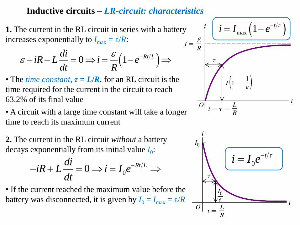
1. The current in the RL circuit in series with a battery
increases exponentially to Imax = ε/R: max 1 ti I e
0
ti I e
Inductive circuits – LR-circuit: characteristics
• The time constant, τ = L/R, for an RL circuit is the
time required for the current in the circuit to reach
63.2% of its final value
• A circuit with a large time constant will take a longer
time to reach its maximum current
0 1 Rt LdiiR L i e
dt R
00 Rt LdiiR L i I e
dt
2. The current in the RL circuit without a battery
decays exponentially from its initial value I0:
• If the current reached the maximum value before the
battery was disconnected, it is given by I0 = Imax = ε/R

• An inductor connected across a charged capacitor form an electric oscillator with
oscillating current and charge called a dc-LC circuit. Functionality:
1. As the capacitor discharges, current increases from 0 to a maximum value and the
potential difference across both elements decreases gradually to 0: the electric energy
is stored in the form of magnetic energy
2. When the current reaches its maximum, the capacitor starts to recharge with an
inverse polarity than initially until the current is again zero and the process restarts in
the reverse direction
cycle
Inductive circuits – LC-circuit: principles
electric
energy
magnetic
energy

• The SHO solutions are
Charge:
Current:
0 0 L C
di qv v L
dt C
1 LC
cosq Q t
maximum charge initial phase angle given
by the charge at t = 0
sindq
i Q tdt
L
div L
dt
C
qv
C
Inductive circuits – RL-circuit: characteristics
• Kirchhoff rule can be applied to find the equation describing the
oscillations of charge and current:
22
20
d qq
dt
Angular frequency ω2 = 1/LC
T
t
2T
cosq Q t
2cosq Q t
T
t
q
Q
2T
T/2 3T/2
– Q
φ = 0
φ = π/2
T
t
iimax
2T
di/dt
–imax
i i
L
C+q –q
• We see that the charge on the capacitor satisfies
an equation similar with that of a Simple
Harmonic Oscillator with angular frequency
max
di
dt
max
di
dt

Problem:
5. LC oscillator: A power supply with emf ε is used to fully charge up a capacitor C. Then the
capacitor is connected to an inductor L.
a) What is the frequency and period of the LC circuit?
b) Find the maximum charge, the maximum current and the maximum rate of change of
current in the circuit.
c) Write out the time dependency of the charge, current and rate of change of current
considering t = 0 the first time when the capacitor holds only half of its maximum charge.
d) Sketch the q vs t graph.
0 x
k
222
2
2
0
SHO
SHO
F kxd x
xd xdtF ma m
dt
2 k
m
Exercise 5: LC oscillations compared with a mechanical
analog: The periodic motion of a Simple Harmonic Oscillator,
containing a mass m connected to a light spring of force
constant k oscillating on a frictionless horizontal surface, is
given by Newton’s 2nd Law as following:
m
Find the oscillating quantities analogue to electric quantities oscillating in the LC circuit:
LC: charge q current i change in current di/dt
Spring: