electrics - Swift Groupassets.swiftgroup.co.uk/swift-group/handbooks/2013 Owners...electrics 69...
22
ELECTRICS 69 ELECTRICS EC444/EC445/EC455 Power Control System ............................................................................. 70 Control Panel Operation .......................................................................................................... 73 Residual Current Device & Miniature circuit breakers ................................................................. 74 Battery charger ......................................................................................................................... 75 Leisure Battery ......................................................................................................................... 75 12 Volt DC Fuses....................................................................................................................... 78 Electrical faults ........................................................................................................................... 81 Technical Data & Approvals ...................................................................................................... 84 Thetford battery box ............................................................................................................... 86 Battery installation ................................................................................................................... 87 Solar panel connection point .................................................................................................... 88 Generator usage ..................................................................................................................... 89 Habitation relay ......................................................................................................................... 89 Exterior 230v socket................................................................................................................... 89
Transcript of electrics - Swift Groupassets.swiftgroup.co.uk/swift-group/handbooks/2013 Owners...electrics 69...

elec
tr
ics
69
electrics
EC444/EC445/EC455 Power Control System ............................................................................. 70
Control Panel Operation .......................................................................................................... 73
Residual Current Device & Miniature circuit breakers ................................................................. 74
Battery charger ......................................................................................................................... 75
Leisure Battery ......................................................................................................................... 75
12 Volt DC Fuses ....................................................................................................................... 78
Electrical faults ...........................................................................................................................81
Technical Data & Approvals ...................................................................................................... 84
Thetford battery box ............................................................................................................... 86
Battery installation ................................................................................................................... 87
Solar panel connection point .................................................................................................... 88
Generator usage ..................................................................................................................... 89
Habitation relay .........................................................................................................................89
Exterior 230v socket ...................................................................................................................89
elec
tr
ics
70
ec444/ec445/ec455 power control system
EC444 / EC445 / EC455 PowEr Control systEm
1. Introduction
This section of the handbook will guide you through the operation of the electrical system.Further technical details are contained in section 3 or in the supporting dealer technical manual available from www.sargentltd.co.uk
For the safe operation of all electrical equipment within your Leisure Vehicle it is important that you read and fully understand these instructions. If you are unsure of any point please contact your dealer / distributor for advice before use.
The system has a number of key components that you will need to be familiar with before attempting to use the system, these are:
• The EC series Power Supply Unit (PSU) - a combined mains consumer unit and 12V controller located in the front locker or bed box area. On locker mounted caravan versions this unit also contains the provision for the Radio/CD head unit. The EC400 / EC450 series of power supply units include the EC400 range (horizontal units) and the EC450 range (vertical units), further details are contained later in this document.
• The EC series Control Panel (CP) - a remotely located user control panel used to turn circuits on and off and to display battery and water tank information. This panel uses simple straightforward controls and reliable data communication to the PSU.
• Road Light Fuse Box - This small unit, which is unique to caravans, is located in the front bed box. The unit houses fuses for the road lighting circuits and supplies from the tow vehicle, and also has connectors for the optional alarm system and Automatic Trailer Control (ATC) unit.
2 Using the system
The PSU is located in the front offside locker area or front bed box in caravans.
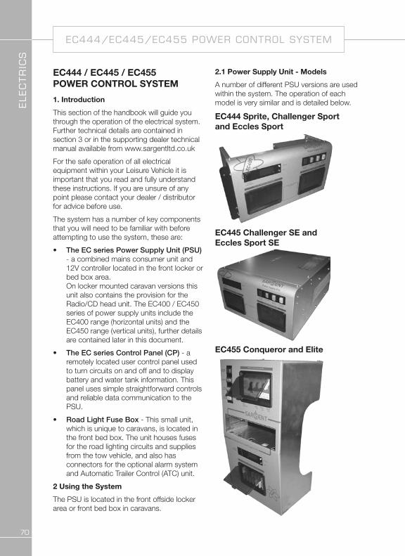
2.1 Power supply Unit - models
A number of different PSU versions are used within the system. The operation of each model is very similar and is detailed below.
EC444 sprite, Challenger sport and Eccles sport
EC445 Challenger sE and Eccles sport sE
EC455 Conqueror and Elite

elec
tr
ics
71
2.2 Power supply Unit - Component layout
230V Components
Red indicator – Reverse polarity indicator, lights up when the 230V supply polarity is reversed.
Green push switch – Charger switch, this switch turns the 12V battery charger on or off. “In” is on “out” is off.
Amber push switch – Combi or Alde boiler, this switch turns the 230V supply to the combination heater / central heating system on or off. In is on out is off.
White - Spare
Black lever switch, far left – Residual Current protection Device (RCD) and main 230V on / off switch.
Yellow button, far left – RCD test button.
Red lever switches, right – 3 x 10A Miniature Circuit Breakers (MCB). Please note that installations with a 3KW Alde heating system will have 2 x 10A and 1x16A MCB’s.
12V Components
Black push switch, far left – System shutdown switch, this switch turns the power control system on or off. In is on out is off.
Yellow push button, top right – Select button, this button is used to scroll through the display items on the LCD screen.
Red push button, bottom right – Set button, this button is used to change the setting of the displayed item on the LCD screen.
12V DC circuit protection fuses. Fuse number 1 is top left; Fuse number 14 is bottom, right. See section 3.5 for full fuse allocation details.
Combi or Alde installations
Space heater /Water heater installations

elec
tr
ics
72
ec444/ec445/ec455 power control system
2.3 Activating the system
The EC400 / EC450 system has a shutdown feature that should be used when the vehicle is in storage or is not being used for long periods of time. This allows the leisure electronics to be turned off when not required to save battery power. When in the off state the alarm and tracking system supplies are still active, most other supplies are turned off.
Before using the system please ensure the shutdown switch is in the system on position (button in).
2.4 Connecting to the mains 230V supply and safety checks
For your safety it is IMPORTANT that you follow these connection instructions each time your Leisure Vehicle is connected to a mains supply. This section assumes that the system is complete and that a Leisure battery has been installed (see 3.4).
A) Ensure suitability of the Mains Supply. Your Leisure Vehicle should only be connected to an approved supply that meets the requirements of BS7671 or relevant harmonised standards. In most cases the site warden will hold information regarding suitability of supply. If using a generator you also need to comply with the requirements / instructions supplied with the generator.
Please note that some electronic generators may not be compatible with your leisure system. Further generator operational information is contained elsewhere in this manual.
B) Switch the PSU internal Power Converter OFF. Locate the green ‘Charger’ power switch on the PSU and ensure the switch is in the off position (button out) before connection to the mains supply.
C) Connect the Hook-up Lead. Firstly connect the supplied hook-up lead (orange cable with blue connectors) to the Leisure Vehicle and then connect to the mains supply.
D) Check Residual Current Device operation. Locate the RCD within the PSU and ensure the RCD is switched on (lever in up position). Press the ‘Test’ button and confirm that the RCD turns off (lever in down position). Switch the RCD back to the on position (lever in up position). If the test button failed to operate the RCD see section 3.10.
E) Check Miniature Circuit Breakers. Locate the MCB’s within the PSU (adjacent to the RCD) and ensure they are all in the on (up) position. If any MCB’s fail to ‘latch’ in the on position see section 3.10.
F) Turn the PSU ON. Locate the black ‘Shutdown’ button and ensure it is in the on position (press button in). Locate the green ‘Charger’ switch on the PSU and turn to the on position (press button in). The charger switch will illuminate when turned on.
G) Check correct Polarity. Locate the ‘Reverse polarity’ indicator on the PSU and ensure that the indicator is NOT illuminated. If the indicator is illuminated see section 3.10.
H) Check operation of equipment. It is now safe to operate the 12v and 230v equipment.
2.5 Control Panel - Component layout
Depending on your type of caravan the control panel will vary in specification.
Not all features are present in all vehicles. Please refer to the following diagrams to identify your control panel.

elec
tr
ics
73
2.6 Control Panel operation
• Power Button. Press the power button to turn the leisure power on. Press the button again to turn the power off. The adjacent LED will illuminate when the power is on, and also the voltage of the selected battery will be displayed on the voltage gauge.
• Pump Button. With the power on, press the pump button to turn the water pump on. Press the button again to turn the pump off. The adjacent LED will illuminate when the pump is on, and also the level of the water tank will be displayed on the water gauge.
• View Levels. To display the battery voltage levels and the water tank levels on the control panel gauges, press the levels button. The display will remain illuminated for 10 seconds. It is possible to lock the
display ‘on’ to allow continuous display. This can be achieved by pressing and holding the view levels button for 2-3 seconds until you hear a beep. To turn this locked feature off, either press and hold the view levels button again for 2-3 seconds or turn the power off and back on.
• Battery Select. By default, the leisure battery is selected as the power source if no mains supply is present, or as the battery to be charged when the mains supply is available. To change the selected battery, press the vehicle battery select button. The selected battery is indicated by an LED adjacent to the caravan or car logo.
• Mains on indication. When connected to a 230v supply the LED with a “lightning strike” shown will be illuminated.
Fresh water level gauge
Mains supply & charger on
Leisure battery selected LED
Vehicle battery selected LED
Vehicle battery selection button
Vehicle battery voltage gauge
View levels button, press to show battery & tank levels
Power on/off button
Water pump on/off button
Tank fill on/off button
Leisure battery voltage gauge
EC451 - Caravans with water tanks
EC442 - Caravans without water tanks

elec
tr
ics
74
ec444/ec445/ec455 power control system
• Charging when the vehicle engine is running. When the vehicle engine is running both the vehicle battery and the leisure battery LED’s will flash in unison to indicate that they are connected together and are being charged by the vehicle.
• Tank Fill Button. For some caravans, with the power on, press the tank fill button to turn the external filler pump on or off. Please ensure you switch the fill button off when the external tank is empty to prevent damage to the pump.
2.7 operation while driving
The EC system is designed to shutdown parts of the system while the engine is running. This is to meet Electro Magnetic Compatibility (EMC) regulations and to ensure the safe operation of the caravan. This is indicated by the two battery LED’s flashing together.
Please ensure the system shutdown switch on the PSU is in the “on” (button in) position before driving (see 2.3). This will ensure the electronic system is active and will therefore be able to control the charging process, supply the refrigerator and monitor other system circuits.
3 system technical Information
The following section provides further technical information relating to the electrical system. You can also access the supporting technical manual from www.sargentltd.co.uk
3.1 residual Current Device & miniature Circuit Breakers
Residual Current Device (RCD)
Miniature Circuit Breakers (MCB’s)
RCD Test
button
The Residual Current Device (RCD) is basically provided to protect the user from lethal electric shock. The RCD will turn off (trip) if the current flowing in the live conductor does not fully return down the neutral conductor, i.e. some current is passing through a person down to earth or through a faulty appliance.
To ensure the RCD is working correctly, the test button should be operated each time the vehicle is connected to the mains supply (see section 2.4)
The Miniature Circuit Breakers (MCB’s) operate in a similar way to traditional fuses and are provided to protect the wiring installation from overload or short circuit. If an overload occurs the MCB will switch off the supply. If this occurs you should investigate the cause of the fault before switching the MCB back on.

elec
tr
ics
75
The following table shows the rating and circuit allocation for the three MCB’s
mCB rating output wire colour Description
1 10 Amps White 230v Sockets
2 10 Amps White (Yellow for heater)
Extra 230v Sockets / Space Heater
2 16 Amps Yellow Alde heating (EC470 PSU only)
3 10 Amps Black (Blue for water heater)
Fridge / Water heater / 12v Charger (internally connected)
3.2 Battery Charger
The EC444 / EC445 / EC455 system incorporates an intelligent three-stage battery charger / power converter.
During stage 1 the battery voltage is increased gradually while the current is limited to start the charging process and protect the battery. At stage 2 the voltage rises to 14.4V to deliver the bulk charge to the battery. When the battery is charged, the voltage is decreased at stage 3 to 13.6V to deliver a float charge to maintain the battery in the fully charged state. The charger can be left switched on continuously as required.
The battery charger / power converter also provides power to the leisure equipment when the mains supply is connected. This module supplies DC to the leisure equipment up to a maximum of 25 Amps (300 Watts), therefore the available power is distributed between the leisure load and the battery, with the leisure load taking priority as per the following example:
lesiure load Available power for battery charging
5A 20A
10A 15A
15A 10A
20A 5A
wArnInG: Under heavy loads the Charger case may become hot. ALWAYS ensure the ventilation slots have a clear flow of air. Do not place combustible materials against / adjacent to the Charger
3.3 leisure Battery
A) type / selection
For optimum performance and safety it is essential that only a proprietary brand LEISURE battery is used with a typical capacity of 75 to 120 Ah (Ampere / hours). A normal car battery is NOT suitable.
This battery should always be connected when the system is in use. The PSU is configured to work with standard lead acid leisure batteries, and in most cases is also compatible with the latest range of Absorbed Glass Matt (AGM) batteries. Before fitting non-standard batteries please check that the charging profile described in 3.2 is suitable for the type of battery by referring to the battery documentation or battery manufacturer.
The battery feed is fitted with an inline fuse between the battery and the electrical harness, and is usually located immediately outside the battery compartment or within 500mm of the battery. The maximum rating of this fuse is 20A per battery.

elec
tr
ics
76
ec444/ec445/ec455 power control system
B) Installation & removal
Always disconnect the 230v mains supply and turn the PSU green charger switch to the off position (button out) before removing or installing the battery.
When connecting the battery, ensure that the correct polarity is observed (black is negative [-] and red is positive [+]) and that the terminals are securely fastened. Crocodile clips must not be used.
WARNING: Explosive gases may be present at the battery. Take care to prevent flames and sparks in the vicinity of the battery and do not smoke. Switch off all appliances and lamps before connecting or disconnecting the leisure battery.
C) operation / servicing
Under normal circumstances it should not be necessary to remove the battery other than for routine inspection of the terminals and “topping up” of the battery fluid where applicable. Please see instructions supplied with the battery.
note: Do not over discharge the battery. one of the most common causes of battery failure is when the battery is discharged below the recommended level of approximately 10v. Discharging a battery below this figure can cause permanent damage to one or more of the cells within the battery.
12V operation of Electrical Items
Most appliances within your product are designed to function when supplied with a 12V feed, either from a leisure battery or the on-board charger.
However, customers should note that some items may have limited functionality when the battery is in a lower voltage state (i.e. circa 10V). The Swift Group makes every effort when specifying components to operate at low voltages, but is not responsible if a component fails to work at lower voltages.
Components that are typically affected by low battery voltage include, but are not limited to, the pump, the radio and some lights which require higher voltages for start-up.
To prevent over discharge, the EC400-450 system incorporates a battery protect circuit that warns the users and then disconnects the batteries when they fall below set values.
If the power is turned on and the leisure battery level falls below 9V a warning beep will be heard and the leisure battery gauge 10V LED will flash. To cancel the warning, press the levels button.
If the power is turned on and the vehicle battery level falls below 10.9V a warning beep will be heard and the vehicle battery gauge 10V LED will flash. To cancel the warning, press the levels button.
These warnings will not be repeated unless the power switch is turned off and on again. This is to ensure the warning does not become a nuisance.
elec
tr
ics
77
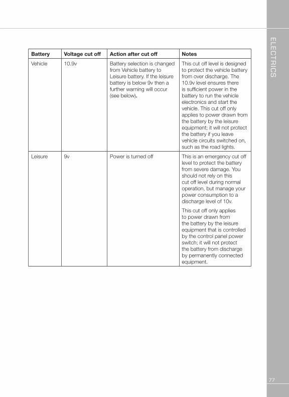
Battery Voltage cut off Action after cut off notes
Vehicle 10.9v Battery selection is changed from Vehicle battery to Leisure battery. If the leisure battery is below 9v then a further warning will occur (see below).
This cut off level is designed to protect the vehicle battery from over discharge. The 10.9v level ensures there is sufficient power in the battery to run the vehicle electronics and start the vehicle. This cut off only applies to power drawn from the battery by the leisure equipment; it will not protect the battery if you leave vehicle circuits switched on, such as the road lights.
Leisure 9v Power is turned off This is an emergency cut off level to protect the battery from severe damage. You should not rely on this cut off level during normal operation, but manage your power consumption to a discharge level of 10v.
This cut off only applies to power drawn from the battery by the leisure equipment that is controlled by the control panel power switch; it will not protect the battery from discharge by permanently connected equipment.

elec
tr
ics
78
ec444/ec445/ec455 power control system
3.4 12 Volt DC Fuses
WARNING: When replacing fuses always replace a fuse with the correct value. NEVER replace with a higher value / rating as this could damage the wiring harness. If a replacement fuse ‘blows’ do not keep replacing the fuse as you could damage the wiring harness. Please investigate the fault and contact your dealer.
The following table shows the fuse allocation for the 15 fuses fitted to the PSU. Please note that fuses are dependant on PSU versions, so not all fuses may be present.
Fuse rating Fuse colour Description
1 20 Amps Yellow Not used in caravan application
2 15 Amps Blue Not used in caravan application
3 7.5 Amps Brown Not used in caravan application
4 15 Amps Blue Not used in caravan application
5 10 Amps Red Extractor Fans / Combination Heating Systems
6 10 Amps Red 12V Sockets / TV Amp / Radio (caravan radio supply)
7 10 Amps Red Front Internal Lighting
8 10 Amps Red Water Pumps / Toilet
9 15 Amps Blue Not used in caravan application
10 10 Amps Red Not used in caravan application
11 10 Amps Red Bathroom lights
12 5 Amps Tan Electronics / Fridge / Alarm
13 5 Amps Tan Oven Ignition / Water Heater (where applicable / Separate water heater)
14 10 Amps Red Rear Internal Lights
15 25 Amps White Charger (fitted internally to PSU)
The following table shows details of the fuse(s) located at the Leisure battery. See also 3.3A
Fuse rating Fuse colour Description
Battery 1 20 Amps Yellow Fuse remotely located near battery

elec
tr
ics
79
The following table shows details of the fuse(s) located at the Road Light fuse box, on the front wall inside the front bed.
Fuse rating Fuse colour Description
1 20 Amps Yellow Fridge Supply 12V
2 5 Amps Tan Left Hand Tail Lights
3 5 Amps Tan Right Hand Indicators
4 5 Amps Tan Fog Lights
5 Spare location
6 20 Amps Yellow Car Battery Supply 12V
7 5 Amps Tan Right Hand Tail Lights
8 5 Amps Tan Left Hand Indicators
9 7.5 Amps Brown Stop Lights
10 5 Amps Tan Reverse Lights
3.5 system status and Configuration display
Depending on specification, the PSU may feature an LCD display and two control buttons that allow system information to be viewed or settings changed.
Press the top yellow ‘select’ button to change the item being viewed. Press the bottom red ‘change’ button to change the setting. Both buttons work on a continuous loop, so if you want to return to an item or setting keep pressing the button until the required item is reached.
3.6 water system operation
The control panel pump button operates the internal (onboard) water pump. This pump will draw water from the internal (onboard) water tank (if fitted) or the external water inlet, depending on the position of the manual supply selector valve.
The system also incorporates a separate powered water inlet that can be used with an external filler pump to fill the internal (onboard) water tank (if fitted).
user when the fresh water level drops below 25% or when the waste water level reaches 100%. If the water pump power is turned on and the fresh water level drops to below 25% a warning beep will be heard and the fresh gauge empty LED will flash. To cancel the warning, press the levels button.
If the water pump power is turned on and the waste water level rises to full (100%) a warning beep will be heard and the waste gauge full LED will flash. To cancel the warning, press the levels button. These warnings will not be repeated unless the water pump power switch is turned off and on again.
This is to ensure the warning does not become a nuisance.

elec
tr
ics
80
ec444/ec445/ec455 power control system
3.7 warnings and Alerts
If the vehicle engine is started whilst the caravan is connected to the 230v supply, a warning beep will be heard. This is to warn you to remove the 230v supply before driving away.
When the vehicle engine is running both the vehicle battery and the leisure battery LED’s will flash in unison to indicate that they are connected together and are being charged by the vehicle.
Low water level and waste tank, if the fresh water level drops to below 25% a warning beep will be heard and the fresh gauge empty LED will flash. To cancel the warning, press the levels button. If the waste water level rises to full (100%) a warning beep will be heard and the waste gauge full LED will flash. To cancel the warning, press the levels button.
Low voltage warning and cut off, if the power is turned on and the leisure battery level falls below 9V a warning beep will be heard and the leisure battery gauge 10V LED will flash. To cancel the warning, press the levels button. If the power is turned on and the vehicle battery is selected (being used) and the level falls below 10.9V a warning beep will be heard and the vehicle battery gauge 10V LED will flash. To cancel the warning, press the levels button.

elec
tr
ics
81
power control system faults
3.8 Common Fault table
Fault Possible Cause Proposed Fix
No 230 volt output from PSU
Connecting lead between the site and Leisure Vehicle not connected
Check and connect lead as per 2.4C
RCD switched off Reset RCD as per 2.4D
RCD not operating correctly Check supply polarity; if the RCD continues to fail contact your Dealer as there is probably an equipment or wiring fault.
MCB switched off Reset MCB by switching OFF (down position) then back ON (up position), if the MCB continues to fail contact your Dealer as there is probably an equipment or wiring fault.
No or deficient supply from site
Contact site Warden for assistance
Other fault Contact your Dealer
Reverse Polarity light is illuminated on PSU
Mains Supply reversed? The reverse polarity light is designed to illuminate when the Live and Neutral supply has been reversed / crossed over. If the light illuminates there is a problem with the site supply or the cable connecting the supply to your vehicle. The light is designed to work on UK electrical supplies (where the neutral conductor is connected to earth at the sub station). If you are using your vehicle outside the UK this light may illuminate when no fault exists. In these cases consult the site warden for advice.

elec
tr
ics
82
3.8 Common Fault table
Reverse Polarity light is illuminated on PSU
Generator being used ‘The Reverse Polarity warning light is on when using my Generator’. This is a normal side effect when using some types of generator. Instead of connecting the neutral conductor to earth, some generators centre tap the earth connection making both neutral and live conductors 110v above earth. This 110v difference causes the neon polarity indicator to illuminate. In most cases it is still safe to use the generator, but please consult the generator handbook for further information.
Control Panel Problems
Control Panel has no display Check batteries and fuses, turn PSU shutdown switch and charger switch on and ensure mains supply is connected.Check control panel connecting lead at PSU and behind Control Panel.
Contact your Dealer
12v Power turns off Battery protect feature has operated to protect the Vehicle battery and or the Leisure battery. See 3.4C
Engine has been started, all equipment has been disconnected to meet EMC requirements. See 2.7
Control Panel locked / erratic function
Observe control panel handling instructions
Control panel software may have crashed. Reboot control panel by turning off the PSU isolate switch. Wait 30 seconds then turn the switch back on.
power control system faults

elec
tr
ics
83
No 12 volt output from PSU
No 230v supply Check all above
Charger not switched on Turn charger switch on, switch will illuminate
Battery not connected and / or charged
Install charged battery as per 3.4
Power button on control panel not switched to on
Turn power on at control panel
Battery flat / Battery fuse blown
Recharge battery, check fuses, check charging voltage is present at battery
Fuse blown Check all fuses are intact and the correct value fuse is installed as per fuse table
Equipment switched off /unplugged
Check equipment is switched on and connected to the 12v supply
PSU overheated / auto shutdown operated
Reduce load on system. Allow PSU to cool down. PSU will automatically restart when cool.
Other fault Contact your Dealer
Pump not working Fuse blown Replace fuse with correct value as per fuse table.
Pump turned off Turn pump on by pressing the pump button at the control panel.
Setting incorrect Both the internal and external pump feeds are controlled from the control panel. To alter the setting of the pump switch see section 3.8
Ensure the setting matches your desired requirement.
3.11 Contact details
Sargent Electrical Services Limited, provide a technical help line during office hours. Please contact 01482 678981 if you require technical help. For out of hour support please refer to the tech support section of the Sargent web site www.sargentltd.co.uk

elec
tr
ics
84
4 technical Data & Approvals
4.1 Caravan Equipment –
outline specification
INPUT 230v 230 Volts / 0 to 16 Amps + / - 10%
OUTPUT 230v RCD protected, 3 x MCB outputs of 10A
Separate switched channels for water heater, space heater and charger
INPUT 12v 2 x 20A battery inputs via 2 x 4 way connectors
OUTPUT 12v 25A total output via multiple switched channels protected by 14 fused outputs
CHARGER Input 220-240 Volts AC +/- 10%, Frequency 50 Hz +/- 6%, Current 3A max.
DC Output 13.6 to 14.4 Volts nominal, Current 25 Amps max (300 Watts).
Overall size (HxWxD) 50 x 250 x 135mm
Fixing centres 128*128mm 1.2kg
Signal INPUT 4 x Fresh water level, 1 x Engine running, plus multiple vehicle connections
Fresh water negative sensed
Data IN / OUT CANBUS Data communication and power to Control Panel via 6 way connector
IP rating IP31
Operating temperature Ambient 0 to 35°Centigrade
PSU case temperature with full load 65°C Max
Automatic shutdown and restart if overheated / overloaded
technical data & approvals

elec
tr
ics
85
4.2 Approvals
System: BSEN 1648-1, BSEN1648-2 compliant, BS7671: 2008 compliant
Residual Current Device: RCD 40A 30mA trip to BS EN 61008
Miniature Circuit Breakers: MCB’s type C 6000A breaking capacity to BSEN 60898
Electro Magnetic Compatibility (EMC) directive 2004/108/EC Certificate CE20071224-1
Integrated Charger: BS EN 60335-1/2.29, 2006/95EC, IEC61000-3.2/3:1995, 1.
Low Voltage Directive: 2006/95EC TUV-014900-A1, EN55022, Class B, EN55024/ Level 2

elec
tr
ics
86
battery box
The Battery Box is intended to accommodate an auxiliary battery in your caravan. The Battery Box has a CE socket to connect to a 230 V power supply. Inside the Battery Box there is the option to fit several sockets and outlets.
wArnInG:
•Useprecautionwhenmountingthebattery, as batteries contain acid liquids which can cause severe injuries and damage when handled incorrectly. Refer to the instructions on the battery.
•NosmokingisallowedintheareaoftheBattery Box!
•PleasenotethattheCEsockethasamaxof 16 amp.
• Thisproductmeetsthelatestversionofthe EN 1648 part 1 and 2 standard.
Before placing the battery inside the Battery Box, the battery should be placed in either the battery bag or the Soft Tray and rested on the ground adjacent to the Battery Box. Carefully connect the electrical wires (the red cable attaches to the + pole and the black cable to the - pole of the battery).
Note! Incorrect connection of the cables will cause a short circuit with potential hazardous consequences.
After mounting the terminals, lift the battery together with the bag or Soft Tray into the middle of the Battery Box compartment. Push the battery to the back of the Battery Box.
Dependant on the model of battery box fitted to your vehicle, the battery is secured by either a strap (figure A), or a facing-clip (figure B).
When attaching the 230 volt cable on the CE socket, the maximum recommended thickness of the cable is 10 mm. When closing the door, the attached cable is to be fed through the slot in the door.
The maximum battery size that can be fitted is 225mm high (including terminals) x 175mm deep x 353mm wide. The depth and width dimensions include the rim around the bottom used for securing the battery.
notE: Batteries that are not foot mounted, ie. without a rim can still be fitted, but check first that they will fit within the battery box and can be secured before purchasing.
Figure A
Figure B
Cleaning and maintenance
• Useprotectiveclothingandglasses when handling a leaking battery, and avoid direct contact to the skin, eyes and respiratory organ.
• Shouldabatteryleakageoccur,pleaseactaccording to the instructions supplied by the manufacturer of the battery. Act with caution as caustic substances are present in the battery.

elec
tr
ics
87
battery installation
• Alwaysremovethebatteryandthepowercable before carrying out any maintenance of the product.
• Beforeremovingtheclampsswitchoff all electrical and gas appliances.
• Useasoftclothorspongeandanon-acid/abrasive detergent when cleaning the battery box, soft tray or bag.
• Tocheckifanyacidispresentinthesofttray or bag, simply press it softly. A strong smell from the soft tray may also indicate spilled acid. Always treat spilled battery acid as hazardous waste. Dispose of spilled battery acid according to the local and national regulations.
• Beforethecampingseasonorextensivetravelling, check the soft tray or bag for faults and replace if necessary.
• Thecleaningofthebatteryboxandsofttray or bag should only be done after all power sources have been switched off, in order to prevent a hazardous situations.
BAttEry InstAllAtIonUnder normal circumstances it should not be necessary to remove the battery other than for routine inspection of terminals and ‘topping up’ if required.
wArnInG: Explosive gases may be present at the battery. Take care to prevent flames and sparks in the vicinity.
Your caravan has been fitted with an in-line fuse between the battery terminal and caravan harness. It is recommended that the fuse rating fitted in this location does not exceed 20 amps.
wArnInG: Switch off all electrical and gas appliances and lamps before disconnecting the battery.
Smoking is prohibited around the battery compartment.
To preserve the life of your leisure battery and charger please observe the following:
i) Do not leave all 12V appliances powered at the same time as this will drain your leisure battery more rapidly.
ii) If all 12V appliances must be powered together, ensure the battery is ‘in-circuit’ and that the battery charger is turned on.
iii) For optimum performance use the transformer/charger unit with a leisure battery attached.
Battery
It is recommended that a good quality rechargeable leisure battery is always in circuit when the system is in use.
A deep cycling heavy duty 12V battery should be purchased to provide power for lights and other electrical appliances.
A proprietary brand leisure battery with a minimum of 85 Amp capacity is recommended.
note: 85 Amp batteries and above should be checked dimensionally before purchasing, to ensure fitment within the battery compartment, as brands vary in size.
It should be remembered that batteries suitable for the electrical demands of a caravan differ in design from those for use with a car, and whilst the system may operate with a car battery it is strongly recommended that only a leisure type battery, maintained in good condition is used. The battery should be kept topped up at all times if required.
Note: Some models may have more than one 12V socket fitted, the 6 Amps indicated is available from the 12V socket provided no other 12V socket is used at the same time.

elec
tr
ics
88
solar panel and generator
solAr PAnEl ConnECtIon PoInt (where supplied - model specific)A connection point has been included in the caravan electrical harness to take a 12V supply from an aftermarket solar panel (or similar device), to the caravan leisure battery.
The solar panel must provide a fused and regulated output in order to connect to this point. The connection point can be found inside the caravan adjacent to the battery box, in close proximity to the battery box fuse. Through the floor close to the battery box is a cable pass through, allowing a pair of wires from an externally located device to pass from exterior to interior to meet the connection point. This cable pass through will be capped both internally and externally with a cable entry gland.
A kit of parts is available from your caravan supplier which provides the mating half of the connection point. (The White rectangular connector found inside the caravan is a two way JST-LR type connector). For further assistance in identifying the connection, wire colours leading to the connector are detailed in the wiring schematic in your caravan service book.
EC444 / EC445 / EC455 solar Energy system
Depending on specification, your tourer may be fitted with a 20w solar panel and regulator.
This solar panel and regulator may provide additional 12v power whenever sunlight is available to the panel. This will be directed to the leisure battery whether the control panel is ON or OFF, and regardless of the position of
the SYSTEM SHUTDOWN button. If a factory fitted alarm system is present, that alarm will in turn be able to use the leisure battery as a power supply.
solar power:
Performance
• Output20W+/-1.5%around1.17A
• Chargingcurrent,deliveringabout8.5amphours in to the battery per sunny day.
• Thesystemkeepstheleisurebattery'topped up' during storage and will provide a daily boost to the leisure battery when camping without a mains 230V supply.
Battery power
As the 20 W solar panel operate depending on the state of the charge of the battery it may take a few hours to several days to recover a discharged battery. For obvious reasons the solar panel will only work during daylight hours.
regulator operation
There are two LED located on the solar regulator. The first is the 'power' LED this flashes when the solar panel produces energy, the flash rate increases with the amount of sun light on the solar panel, this will increase until the LED is on solidly. The second LED is bi-coloured. It will indicate the charge condition when sufficient energy is being received by the solar panel. If LED is illuminated red, it is then the regulator is in bulk charge mode 14v plus, if the LED is illuminated green then the regulator is in float charge mode 13.6v.
Power supply Unit
The PSU does not need to be switched on for the solar panel to charge the battery, but if the PSU has an LCD then this can be used to see the lift in the battery voltage as the solar panel charges the battery.
maintenance and cleaning
The solar panel will require cleaning periodically in order to maintain the performance of the panel, a caravan, car shampoo or simple soap can be used, no abrasive cleaners should be used.

elec
tr
ics
89
Control Panel
When the solar panel is operating the voltage display on the leisure battery will increase if the loads placed on the battery are sufficiently light.
GEnErAtor UsAGECaution should be used before connecting a generator to your caravan.
wArnInG: Never start or stop the generator while electrical loads are connected and switched on. Start the engine, let it stabilise, then connect the electrical load. To stop engine, disconnect the electrical load and let engine stabilise before switching off.
Whilst some generators use invertor technology, others use a more basic principle to generate the 230v supply. Preference should be to choose a generator which produces a consistent sinusoidal wave form with accurate voltage control.
The reverse polarity warning light may illuminate when using a generator. This is a normal side effect when using some types of generator. Instead of connecting the neutral and live conductors 110v above earth. This 110v difference causes the neon polarity indicator to illuminate.
In most cases it is safe to use a generator, but please consult the generator handbook for further information.
hABItAtIon rElAyHabitation relays are fitted to caravans by manufacturers to comply with the following legislation:
1. The Road Vehicles (Construction and Use) Regulations 1986 Regulation 60 - Radio interference suppression
2. Council Directive 72/245/EEC of June 20, 1972 amending for the purpose of their adaptation to technical progress, relating to the radio interference (electromagnetic compatibility) of vehicles and Council Directive 70/156/EEC on the approximation of the laws of the Member States relating to the type-approval of motor vehicles and their trailers.
A habitation relay must be fitted by manufacturers, safe guarding the consumer. The purpose of the relay is to disable non-homologated appliances/components whilst the vehicle is in transit.
Unitentional electromagnetic energy can be created by non-homologated devices within the habitation compartment, which could cause a malfunction of the base vehicles electronic systems/components, including safety critical items such as air bags, ABS braking etc.
ExtErIor 230V soCkEtThe recessed electric socket is designed to give you a convenient electrical access point on the outside of the caravan, which is completely protected from the weather, even when in use.
With the caravan stationary and connected to a 220v/240v supply, raise the front cover of the socket and insert the plug of the equipment to be used. Close and latch the cover into place to provide a weatherproof seal.
Please remember that the equipment plugged into the socket may or may not be weatherproof.
habitation relay & exterior 230v socket

elec
tr
ics
90
To disconnect equipment, raise socket cover and remove plug, then close and latch the cover into place to ensure a weatherproof seal.
Before moving the caravan from a pitch ensure that all accessory points are disconnected and latched in the closed position to prevent the ingress of water or other foreign matter from causing damage to the point or any of the caravans services.
Any item plugged into this socket will be supplied by the same 10A breaker (MCB) as the other items plugged into sockets within the caravan. Please take into account the total loading placed on the socket circuit and the site supply before switching equipment on. The socket should be used to power a single appliance with an appropriate power consumption rating – the socket is not suitable for use as a supply to power an adjacent caravan or motorhome.
electrics