
Swift Caravans 2004 - Swift Groupassets.swiftgroup.co.uk/uploads/HandBooks/caravans... · Swift...
146
Swift Caravans 2004 Owner's Handbook
Transcript of Swift Caravans 2004 - Swift Groupassets.swiftgroup.co.uk/uploads/HandBooks/caravans... · Swift...

SwiftCaravans
2004
O w n e r ' s H a n d b o o k

Introduction
INTRODUCTIONDEAR OWNER,
THANK YOU FOR DECIDING TO BUY ONEOF OUR NEW CARAVANS. WE ARE SUREYOU WILL ENJOY MANY HAPPY HOURSIN IT AND WE HOPE THE INFORMATIONAND HINTS IN THIS HANDBOOK WILLHEIGHTEN YOUR ENJOYMENT.
THE HANDBOOK HAS BEEN DESIGNEDTO GIVE YOU A GENERAL GUIDE TO THECARE, USE AND MAINTENANCE OF YOURCARAVAN. WHETHER YOU ARE A NEW ORAN EXPERIENCED CARAVANNER THEHINTS WILL HELP TO PROTECT YOURINVESTMENT.
THE INFORMATION CONTAINED WILLANSWER MOST OF YOUR QUERIES, BUTIF THERE ARE ANY ASPECTS WHICH ARENOT COVERED PLEASE CONSULT YOURAPPOINTED DEALER.
HAPPY CARAVANNING!

CONTENTS
The Towing Code
Safety and Security
Services
Electrical Equipment
Fitted Equipment
Maintenance
General Data
THETOWING
CODE
The Caravan Towing Code ...................................................... 2Scope of the Code ................................................................. 2
Caravan Terms .......................................................................... 2Weights .................................................................................. 2
Towing Vehicle Terms .............................................................. 3Weights .................................................................................. 3
Measurement of Noseweight .................................................. 4Type of Driving Licence Held ....................................................4Glossary & Checklist ................................................................ 4Preparing for the Road ............................................................ 7
Checklist ................................................................................ 7Loading & Distribution ........................................................... 7Stability .................................................................................. 8Pre-tow Checklist ................................................................. 10
Moving Off ............................................................................... 15Reversing ................................................................................ 15Speed Limits ........................................................................... 15Caravan Handling ................................................................... 15Motorway Driving ................................................................... 16Changing a Wheel .................................................................. 16Jacking Points ........................................................................ 16Stopping on a Hill ................................................................... 17Arrival on Site ......................................................................... 17

The Towing Code
THE CARAVAN TOWING CODEThis Code of Practice containsrecommendations jointly reviewed andagreed by the following organisations:
The National Caravan CouncilThe Caravan ClubThe Camping and Caravanning ClubThe Caravan Writers GuildThe Department of Transport
Scope of the CodeThe Code applies to all trailer caravans ofmaximum laden weight not exceeding 3500 kg (7,700 lbs), overall width notexceeding 2.3m (7ft 6in approximately) andoverall length not exceeding 7m (23ftapproximately), excluding the drawbar andcoupling.
This is legally the maximum size of trailerthat can be towed by a motor vehicle with amaximum gross weight of less than 3500 kg.
CARAVAN TERMSMass in Running Order: The mass of the caravan as stated by thecaravan manufacturer, as new with standardfixtures and fittings.
Note: Because of differences in the weightof materials supplied for the construction ofcaravans, a tolerance of +2% of the weighthas been allowed in the Mass in RunningOrder weight.
Maximum User Payload:The maximum allowable weight to be putinto the caravan whilst it is being towed. Thisis made up of 3 sections:
Personal effects, optional equipment andessential habitation equipment.
The user payload is the difference betweenthe Maximum Technically Permissible LadenMass and the Mass in Running Order.
Essential Habitation Equipment:Those items and fluids required for safe andproper functioning of the equipment forhabitation as defined by manufacturer of thecaravan.
Personal Effects:Those items which a user can choose tocarry in a caravan and which are notincluded as Essential Habitation Equipmentor Optional equipment.
Optional Equipment:Items made available by the manufacturerover and above the standard specification ofthe caravan.
Maximum Technically Permissible LadenMass:The maximum weight for which the caravanis designed for normal use when beingtowed on a road, laden. This mass takes intoaccount specific operating conditionsincluding factors such as the strength ofmaterials, loading capacity of tyres etc.
WARNING: Under no circumstancesshould the maximum technicallypermissible laden mass of this caravanbe exceeded.
Nose weight:That part of the static mass of the caravansupported by the towing device on the rearof the towing vehicle.
Notes:(i) When measuring the noseweight it is
important that the caravan is fully loaded. Do not place extra items indiscriminately into the caravan after this adjustment has been made.
(ii) The caravan is intended to be towed slightly nose heavy. The nose weight can be adjusted by distribution of the load within the caravan. The nose weight should be approximately 7% of the actual laden weight (but not greater than the hitch capacity) and at the same time suit the towing vehicle. See section on Measurement of Nose Weight.
(iii) It is not recommended that you tow with just a battery, spare wheel and gas bottles as this may exceed the the permitted nose weight. Additional payload must be placed behind the axle to compensate for this.
2

The Towing Code
TOWING VEHICLE TERMSKerb weight (Mass of Vehicle in RunningOrder):The weight of the towing vehicle as definedby the vehicle manufacturer. This is normallywith a full tank of fuel, with an adequatesupply of liquids incidental to the vehiclespropulsion, without driver or passengers,without any load except loose tools andequipment with which the vehicle is normallyprovided and without any towing bracket.
Caravan to Towing Vehicle Weight Ratio:The towing vehicle to caravan weight ratiocan be determined by calculation and isequal to:
actual laden weight of caravanx 100%
Kerb weight of towing vehicle
THE LAW REQUIRES THAT CARAVANS &THEIR TOWING VEHICLES & THE LOADSTHEY CARRY MUST BE IN SUCH ACONDITION THAT NO DANGER ORNUISANCE IS CAUSED.
(Regulation 100 of the Road and Vehicles[Construction and Use] Regulations 1986).
Power to weight ratio:No hard and fast rules can be stated but,here is a general guide.
(a) Conventional petrol engines with a capacity up to approximately 1500 cc should be adequate for towing a
caravan weighing around 85% of the kerb weight of the towing vehicle.
(b) Above 1500 cc such engines should manage a caravan weighing up to 100% of the kerb weight of the towing vehicle and still give adequate performance.
Note: The towing vehicle manufacturer’s limitis, in some cases, less than the kerb weight.
Vehicles with automatic transmission mayneed an oil cooler fitting or the SAE rating ofthe gearbox oil increasing when towing. Theadvice of the vehicle manufacturer should besought.
Mass in Running Order:Caravanners can use a public weighbridge toestablish the mass in running order.
Note: Weighbridges have varying weighttolerance levels.
Maximum Permissible Towing Mass:The weight defined by the vehiclemanufacturer as being the maximum that the vehicle is designed to tow.
Train Weight (Combination Weight):The maximum combined weight of thetowing vehicle and trailer combination asspecified by the towing vehicle manufacturer.
3
Fig. A Car/Caravan Weight Ratios
YES NO
MAYBE
85%
EQUAL

The Towing Codelower jockey wheel before entering thecaravan and then raise before measuringagain. (See Loading).
Note: The height of the towball on thetowing vehicle, when laden, is also critical.
TYPE OF DRIVING LICENCEHELDIn order to be able to tow a caravan a drivermust hold a Category B licence. Those cardrivers who passed their tests prior to 1January 1997 would have automaticallyobtained Category B+E. However, anyonewho passed their test after 1 january 1997will need to take a further test in order toobtain a Category B+E if they wish to tow acar and caravan combination whose trainweight exceeds 3,500kg, or up to 4,250 ifthe caravan is less than 750kg or if thecaravan’s Maximum Technically PermissibleLaden Mass exceeds the unladen weight ofthe car.
Note: The unladen weight of a car isnormally less than the kerbside weight.
GLOSSARY & CHECKLISTAwnings - Can consist of just a simple topsheet but may extend to a five sided frametent attached to the side of the caravan.
Fire blanket - approved to BS 6575 is idealfor dealing with ‘fat pan’ fires.
Fire extinguisher - It is stronglyrecommended that a fire extinguisher iscarried in the caravan. (For suitable typessee Safety and Security).
Gas bottles - Bottled L.P. gas is the mostconvenient portable source of fuel. Twobottles are required for a constant supply. Aninitial deposit is payable on each cylinder.We recommend the use of 6kg Propane or7kg Butane bottles. One position for use andone for storage only. (For detailedinformation see Services - Gas).
Jack - A suitable jack is essential (screw,scissor, side mounted or air jack type). Manycar jacks are unsuitable.
Levellers - Levellers help level the caravanfrom side to side before unhitching.Proprietary products can be purchased fromyour caravan dealer and need to bepositioned as indicated by a spirit level.
Spare Wheel - It is always advisable to carrya spare wheel with your caravan.
Spirit Level -A spirit level is extremely usefulwhen siting the caravan.
Stabiliser -Stabilisers help to dampen theside to side movement of the caravan. Oneend fits to the car’s towing bracket and theother end to the caravan. (See Stability)
MEASUREMENT OF NOSEWEIGHTNoseweight may be measured using apropriety brand of noseweight indicator.
Such equipment is obtainable at yourCaravan Dealer.
Note: These indicators have a varyingtolerance level.
Another simple method is to use bathroomscales under the coupling head with a pieceof wood, fitted between the coupling headand the scales, of such length that thecaravan floor is horizontal with the jockeywheel raised clear of the ground. (Fig. A)
Noseweight can be adjusted simply bydistribution of weights in the caravan. Always
4
430mm35mm
Fig. A Measuring Noseweight
+-

The Towing Code
5
Torque Wrench - A torque wrench is theonly way that the exact recommendedtorque can be achieved for wheel nuts andbolts. (See Preparing for the Road).
Towing Bracket - Never use cheapalternatives, obtain one manufactured by areputable company complying with therelevant standards.
Any light passenger vehicle registered in theUK on or after August 1st 1998 (S registeredplate) will require a type approved towbarand towball (to 94/20/EC). Failure to fit ahomologated towbar and towball couldresult in a prosecution and invalidation ofyour insurance cover. Always check withyour car manufacturer or towbarmanufacturer if in doubt.
Wooden Blocks - Wooden blocks typically25cm. square and 2cm. thick are ideal forplacing under corner steadies and jockeywheel when the ground is uneven or soft.
Water Containers - Two containers arerequired, one to carry fresh water to thecaravan and one for waste water, whichneeds to be disposed of properly. Severaltypes are available including jerry cans,folding cans and wheeled containers.
12N & 12S Sockets - Two socketsdesignated 12N and 12S are fitted to yourcar to accept corresponding plugs from thecaravan. These are necessary to energisethe road lights and caravan auxiliary circuitsrespectively.
12 Volt Battery - A deep cycling, heavy dutyleisure type battery should be purchased toprovide back-up power for lights and otherelectrical appliances. (See Battery). Thesecuring arrangements for the batterycompartment require a leisure batterycomplying with EN 60095-2 in particularthose with ledges for fastening to the loweredge of the long sides and having amaximum height of 190mm and width of175mm.
WARNING: Your caravan dealer should be consulted if additional equipment is to be fitted as strong points may or may not be provided in the design.
Note: Fitting additional equipment willreduce the caravan allowable payload.
The Towing Code
6
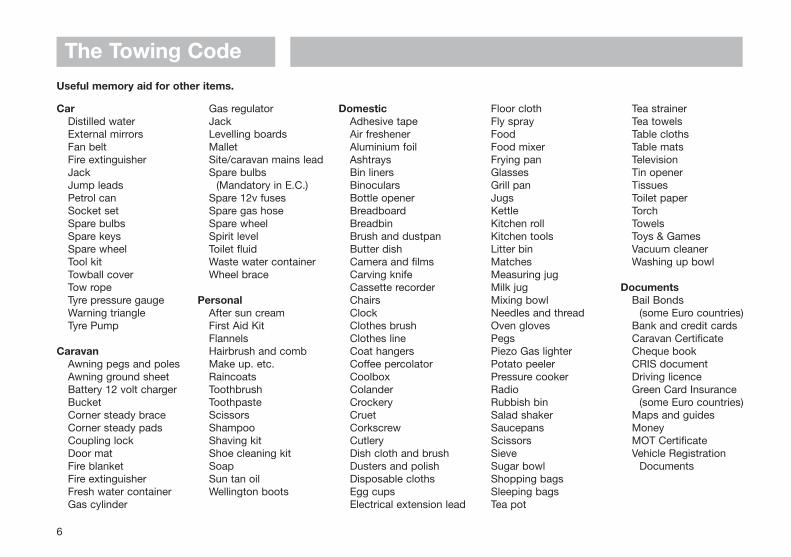
Useful memory aid for other items.
CarDistilled waterExternal mirrorsFan beltFire extinguisherJackJump leadsPetrol canSocket setSpare bulbsSpare keysSpare wheelTool kitTowball coverTow ropeTyre pressure gaugeWarning triangleTyre Pump
CaravanAwning pegs and polesAwning ground sheetBattery 12 volt chargerBucketCorner steady braceCorner steady padsCoupling lockDoor matFire blanketFire extinguisherFresh water containerGas cylinder
Gas regulatorJackLevelling boardsMalletSite/caravan mains leadSpare bulbs
(Mandatory in E.C.)Spare 12v fusesSpare gas hoseSpare wheelSpirit levelToilet fluidWaste water containerWheel brace
PersonalAfter sun creamFirst Aid KitFlannelsHairbrush and combMake up. etc.RaincoatsToothbrushToothpasteScissorsShampooShaving kitShoe cleaning kitSoapSun tan oilWellington boots
DomesticAdhesive tapeAir freshenerAluminium foilAshtraysBin linersBinocularsBottle openerBreadboardBreadbinBrush and dustpanButter dishCamera and filmsCarving knifeCassette recorderChairsClockClothes brushClothes lineCoat hangersCoffee percolatorCoolboxColanderCrockeryCruetCorkscrewCutleryDish cloth and brushDusters and polishDisposable clothsEgg cupsElectrical extension lead
Floor clothFly sprayFoodFood mixerFrying panGlassesGrill panJugsKettleKitchen rollKitchen toolsLitter binMatchesMeasuring jugMilk jugMixing bowlNeedles and threadOven glovesPegsPiezo Gas lighterPotato peelerPressure cookerRadioRubbish binSalad shakerSaucepansScissorsSieveSugar bowlShopping bagsSleeping bagsTea pot
Tea strainerTea towelsTable clothsTable matsTelevisionTin openerTissuesToilet paperTorchTowelsToys & GamesVacuum cleanerWashing up bowl
DocumentsBail Bonds
(some Euro countries)Bank and credit cardsCaravan CertificateCheque bookCRIS documentDriving licenceGreen Card Insurance
(some Euro countries)Maps and guidesMoneyMOT CertificateVehicle Registration
Documents

The Towing Code
7
Fig. A Loading your caravan
(a)
(c)
(b)
(d)
WARNING: Turn off gas appliances except those heating appliances designed to function while the vehicle is in motion.
WARNING: Do not travel with televisions or microwaves in overhead lockers unless the appliance was supplied fitted to your caravan by the manufacturer.
LOADING AND DISTRIBUTION OFWEIGHT IN THE CARAVANDo not exceed recommended maximum loading for your caravan.
1. Load heavy items low down near the floor and mainly over or just in front of the axle(s) (Fig. A).
2. Load evenly right to left so that each
caravan wheel carries approximately the same weight.
3. Do not load items at the extreme front or rear since this can lead to instability due to the ‘pendulum effect’.
4. Load remainder to give a suitable noseweight at the towing coupling.
Check noseweight.
Note: Do not overload car boot.
Note: Please take care to ensure that youhave allowed for the masses of all itemsyou intend to carry in the caravan.
WARNING: All heavy and/or voluminousitems (e.g. TV, radio etc) must be storedsecurely before travelling.
PREPARING FOR THE ROADPRE-LOAD CHECKLISTCaution: Never enter the caravan withoutfirst lowering the four corner steadies withthe brace provided.
BEFORE LOADING CHECK:
- loose articles are stowed securely. Do not stow tins, bottles or heavy items in overhead lockers prior to towing.
- all lockers and cupboard doors are closed and secured.
- all bunks are secure.
- all rooflights are closed and secured.
- main table is stored in its transit position.
- fridge is on 12v operation and door lock is set.
- all windows are fully closed and latched. Never tow with windows on night setting. Leave all curtains and blinds open to aid rear visibility.
- gas cylinders are correctly positioned, secured and turned off.
- battery is secure and mains connecting cable is disconnected and stowed.
- 12v distribution panel selector switch is set to centre position.

The Towing Code
8
Towing vehicle’s rear suspensionIt is important that the towing vehicle’s rearsuspension is not deflected excessively bythe noseweight on the tow ball. If it isexcessive the steering and stability will beaffected. (Fig. B)
The greater the towing vehicle’s tail overhang(the distance between the rear axle and thetow ball) the greater the effect thenoseweight will have on the towing vehicle’srear suspension.
After trying out the caravan it may be foundthat stiffening of the rear suspension isnecessary - but note that this may give thetowing vehicle a firmer ride when not towing.
There are a number of suspension aidsavailable and advice should be sought onwhich to use and how to fit. It is important toensure that the caravan is towed either levelor slightly nose down.
If you have any doubts about the suitabilityof your towbar for towing a caravan consultthe towing bracket manufacturer.
DO NOT exceed the:
• Gross Vehicle Mass (G.V.M. on car plate).
• Maximum Technically Permissible Laden Mass (M.T.P.L.M.) on the caravan.
• Gross Vehicle Combination Mass (Train Weight) (G.V.C.M. on car plate).
• Maximum Permissible Towing Mass.
• Vertical Static Load on the caravan coupling.
• Maximum Vertical Load on the car towballas specified by towing vehicle manufacturer.
STABILITYAll our models are fitted with an Al-Kostabiliser and are of a well balanced designand should be exceptionally good towers.The most common causes of poor stabilityinclude:
(a) Worn springs or loose spring fixings on the towing vehicle.
(b) Towing vehicle springs too soft.
(c) Insufficient noseweight.
(d) Nose of caravan is towing too high.
Fig. A Fig. B Illustration of excessive deflection of vehicle’s rear suspension
Sensible Loading:How to apportion it
LIGHTITEMS
MEDIUMITEMS
HEAVYITEMS

The Towing Code
9
Galvanised steel chassisDrilling of the galvanised steel chassis willinvalidate the warranty and must not bedone.
TowballThe Al-Ko stabiliser fitted is designed to beused with a swan neck, fixed or detachabletowball. If you use a 'bolt on type' towballyou may need to replace your towball with aspecial extended neck towball.
If you have a bolt on type towball you shouldask your dealer to check clearance aroundthe towball to allow for the stabiliser toarticulate.
The Al-Ko extended neck towball (availablefrom your dealer) is approved and markedwith the approval number EC94/20. Failureto provide enough clearance around thetowball may invalidate your stabiliserwarranty.
Stabiliser Friction PadsThe Al-Ko stabiliser uses 'friction pads'inside the coupling head to clamp thetowball. These pads must be kept free fromgrease and contamination from the towball.The friction pads should last approximately50,000km (30,000 miles) under normal use, ifcorrectly maintained.
Suitable towing vehiclesThe caravan is manufactured for towingbehind normal road cars and is not suitablefor towing behind commercial vehicles. It is
strongly recommended that whenever acaravan is to be towed over rough terrain,e.g. a farmer’s field or track, great careshould be taken to ensure that no unduestress is placed upon the caravan via thehitch mounting, i.e. reduce speed. If indoubt, please consult the chassis manufac-turer and the towing vehicle manufacturerwho will advise. Touring caravans based onstandard Al-Ko chassis can be towed byfour wheel drive off road leisure vehiclesproviding the unit is used to tow in a likemanner to a conventional road-going car anddriven in the same considered manner.
Towbar manufacturers should be consultedbefore towing an uncompensated twin axlecaravan.
SnakingThis is a term used to denote an unstablecar and caravan combination where thecaravan ‘weaves’ from side to side oftencausing a similar swaying movement in thecar itself.
Causes:i) Unsuitable or unbalanced outfit.
ii) Incorrect loading or weight distribution.
iii) Excessive speed especially downhill.
iv) Side winds.
v) Overtaking.
vi) Being overtaken by a large fast moving vehicle.
vii) Erratic driving.
viii) Insufficient tyre pressures.
ix) Mixing radial and cross ply tyres.
Cures:Cases of persistent snaking can bealleviated by the use of a stabiliser.
On the roadIf you do find your outfit snaking, try to keepthe steering wheel in a central position as faras possible, decelerate and avoid braking ifpossible.
OTHER IMPORTANT TOWINGCONSIDERATIONS THAT COULD AFFECTSTABILITY
Types of tyres fittedThe tyres fitted by the manufacturer aresuitable for towing at sustained speeds of upto 81 mph (130 kph).
Radial and cross ply tyres should never bemixed. It is dangerous and can causesnaking.
Periodically tyres should be rotated toequalise wear in the same manner as cartyres.
Do not mix four ply/six ply/eight ply tyres onthe same axle.
Tyre treadThe law requires that tyres and pressuresmust be suitable for the use to which theyare being put. The minimum tread depth of

safety. The alternative to steel wheel rims arealloy wheel rims.
If you are in any doubt, have your wheelschecked by a competent tyre supplier.
Hitch head load capacityThe maximum vertical static load which canbe put upon the hitch head when connectedis 100kg. Please refer to the technical data inyour handbook.
(But see also vehicle manufacturer’s weightlimits on towball loading.)
PRE-TOW CHECKLIST AND HITCH-UPCheck Gas Locker, Battery Locker andCassette Toilet doors are secure.
Check wheelnuts, tyre pressures and tyreconditions.
Fully raise all four corner steadies. (Fig. A).
Pick up any levelling pads or levelling boards.
Check rooflights/vents are securely closed.
Switch off gas supply and change over toelectricity if required.
Lock the caravan exterior door.
An assistant can help in the hitchingoperation by standing on the left hand sideof the drawbar (facing rear of car) andextending an arm horizontally to indicateposition of the coupling. When reversing aimthe towball of the car directly at the caravandrawbar. Remove towball cover and keep incar.
Adjust the jockey wheel to ensure the cup ishigh enough to slide over the towball.
WheelsCaravan wheel nuts should be tightened to atorque of 88Nm (65lb/ft) on steel wheels or115Nm (85lb/ft) on alloy wheels and shouldbe checked with the use of a torque wrenchregularly. Only use a spare wheel and tyre ofthe type and size provided with you caravan.
Wheel RimsThe steel wheel rims are the 5J sizeincorporating a double safety hump rimwhich conforms to European standards of
Fig. B Safety Catch and HandleFig. A Winding Corner Steady
The Towing Code
10
both car and caravan tyres must be 1.6mmthroughout a continuous band comprising thecentral three quarters of the breadth of treadand around the entire circumference of thetyre.
Tyre pressuresTowing vehicle's tyres must be at thepressures recommended for towing or heavyloading as stated in handbook not on tyrewall. Towing stability may otherwise beaffected. The pressures can be found in thetowing vehicle handbook. The caravan tyrepressures should be as recommended in thespecification details in your handbook.
Note: Although the caravan may be fittedwith the same type of tyre as the towingvehicle, the pressures specified are different.All charts show values for cars and aretherefore not applicable for caravans.Pressures displayed on tyre walls applyONLY in North America and Canada.

The Towing Code
11
Fig. B Checking Secure Attachment Fig. C Connections - 7 pin PlugFig. A Handbrake
Adjust jockey wheel to lower cup on to theball. A click indicates it is fully engaged. Ensureblack handle has returned to its free position.
Secure caravan handbrake. (Fig. A)
Connect breakaway cable as described onpage 13.
Ensure that the jockey wheel is fully woundup and properly located in the slots, thenrelease the clamp handle, lift the whole unitas high as possible and retighten the clamphandle.
Note: Ensure jockey wheel locates in recessprovided.
Take hold of the caravan under the rubbergaiter behind the coupling and lift to ascertain whether the caravan is properly
attached. (Figs. B & D.)
Fig. D Hitch Head Visual Indicator
Release caravan handbrake.
Position cup over the ungreased towball,release and lift forward the large redstabiliser handle (Fig. B, Page 10), lift forwardthe exposed smaller black handle (Fig. B,Page 10), until it clicks up. The hitch head isfitted with a visual indicator to show whetheror not it is properly connected to the towball.A green band will show immediately belowthe red indicator button on the hitch headwhen a proper connection has been made.(See Fig. D)
WARNING: If the green band is showing when the hitch head is not connected to the towball there is a fault - contact your Dealer.

TERMINAL COLOUR 12N PLUG1 YELLOW L/H INDICATOR2 BLUE REAR FOG LAMP3 WHITE COMMON RETURN (1-7)4 GREEN R/H INDICATOR5 BROWN R/H SIDE TAIL & No PLATE LIGHT6 RED STOP LAMP7 BLACK L/H SIDE TAIL & No PLATE LIGHT
TERMINAL COLOUR 12S PLUG1 YELLOW REVERSING LIGHT2 BLUE NO ALLOCATION3 WHITE NEGATIVE PIN 44 GREEN CONTINUOUS POWER SUPPLY5 BROWN NO ALLOCATION6 RED FRIDGE7 BLACK RETURN FOR FRIDGE
12N AND 12S VIEWED FROM REAR OF PLUG
12N (BLACK) 12S (GREY)
The Towing Code
12
TUBES
PINS
PINS
STRIPS
PIN NO COLOUR DESCRIPTION1 YELLOW LEFT FLASHER2 BLUE FOG HAZARD LIGHT3 WHITE EARTH FOR 1-84 GREEN RIGHT FLASHER5 BROWN RIGHT TAIL LIGHT6 RED STOP LIGHTS7 BLACK LEFT TAIL LIGHT8 ORANGE REVERSE LIGHTS9 BROWN/BLUE CAR +
10 BROWN/RED FRIDGE11 WHITE/BLACK EARTH FOR 1012 NOT YET ALLOCATED13 WHITE/GREEN EARTH FOR 9
VOLTA/JEAGER & MULTICON FEDER 13 PIN PLUGS (viewed from rear)
VOLTA/JEAGER WESTMULTICONFEDER 13K
Lock hitch if possible (see Safety andSecurity, page 22).
Connect 7 pin plugs to car sockets ensuringthere is enough loose cable for cornering.(Fig. C) ensuring they wont drag on theground.
Check all car and caravan roadlights areworking. Check round the caravan foranything left behind.
Release caravan handbrake, adjust all mirrorsfrom driving seat and proceed.
The Towing CodeROAD LIGHTINGFor your information the wiring diagram ofthe 12N and 12S connectors is shownopposite. These should be checked regularlyand if in any doubt a qualified electricianconsulted.
Some European cars may be equipped withVolta, Jeager, West or multi-con sockets, anadaptor or replacement sockets may berequired. If so consult your dealer orqualified electrician.
The wiring allocations were changed in 1998and it is important that you check the car tocaravan connections are compatible prior tocoupling up to the car.
WARNING: Always disconnect the electrical connector between the towingvehicle and the caravan before connecting a low voltage supply to the caravan (mains) and before charging thebattery (EN 1648-1).
• All road lights must be in working order.
• Lenses and reflectors must be in good condition
• Bulbs must be of correct wattage for the application (see Service handbook).
WARNING: Do not cause any road lighting to be obscured by the addition of any options or accessories to your caravan.
PASSENGERSPassengers are forbidden to ride in acaravan.
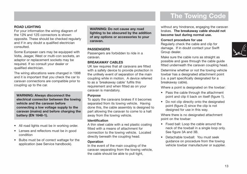
BREAKAWAY CABLESUK law requires that all caravans are fittedwith a safety device to provide protection inthe unlikely event of separation of the maincoupling while in motion. A device referredto as a 'breakaway cable' fulfils thisrequirement and when fitted as on yourcaravan is mandatory.
PurposeTo apply the caravans brakes if it becomesseparated from its towing vehicle. Havingdone this, the cable assembly is designed topart allowing the caravan to come to a haltaway from the towing vehicle.
IdentificationA thin steel cable with a red plastic coatingfitted with a means of attachment forconnection to the towing vehicle. Locateddirectly beneath the coupling head.
OperationIn the event of the main coupling of thecaravan separating from the towing vehicle,the cable should be able to pull tight,
without any hindrance, engaging the caravanbrakes. The breakaway cable should notbecome taut during normal use.
Correct procedure for useRegularly check the cable and clip fordamage. If in doubt contact your SwiftGroup dealer.
Make sure the cable runs as straight aspossible and goes through the cable guidefitted underneath the caravan coupling head.
Determine whether or not the towing vehicletowbar has a designated attachment point(i.e. a part specifically designated for abreakaway cable).
Where a point is designated on the towbar:
• Pass the cable through the attachment point and clip it back on itself (figure 1).
• Do not clip directly onto the designated point (figure 2) since the clip is not designed for use in this way.
Where there is no designated attachmentpoint on the towbar:
• Fixed ball: Loop the cable around the neck of the towball in a single loop only. See figure 3A and 3B.
• Detachable towball: You must seek guidance on procedure from the towing vehicle towbar manufacturer or supplier.
13

The Towing Code
14
When the breakaway cable is attached,check to ensure:
a) that the cable cannot snag in use on the caravan coupling head, jockey wheel, stabiliser or accessory e.g. bumper shield, cycle carrier etc.
b) that there is sufficient slack in the cable to allow the towing vehicle and caravan to articulate fully without the cable ever becoming taut and applying the brakes.
c) that it is not slack and can drag on the ground. If left loose, the cable may scrape along the ground and be weakened so that it subsequently fails to do its job. The cable may also be caught on an obstacle when in motion thus engaging the caravan brakes prematurely.
Having followed this advice, should you feelthat a satisfactory coupling arrangementcannot be achieved, consult your SwiftGroup dealer or towbar supplier.
Fig. 1 Fig. 2 Fig. 3A
Fig. 3B
The Towing Code
15
Fig. A Reversing
MIRRORSThe driver of the towing vehicle must have anadequate view of the rear.
If there is no rear view through the caravan itis essential that additional exterior towingmirrors are fitted. This is mandatory in someEuropean countries and drivers can faceinstant fines if extension mirrors are not fitted.
Caution: Any rear view mirror must notproject more than 200 mm outside:
a) the width of the caravan when being towed.
b) the width of the towing vehicle when driven solo.
Note: Any rear view mirror fitted shall be ‘e’marked and cover the field of view asstipulated by type approval requirements(Regulation 33 of the Road Vehicles[Construction and Use] Regulation 1986).
MOVING OFF
Let the clutch in smoothly.
Allow more engine speed to produce thepower to move the additional weight of thecaravan.
Reduce wear and tear on clutch andtransmission by taking extra care.
Change gears smoothly.
Try not to jerk the clutch.
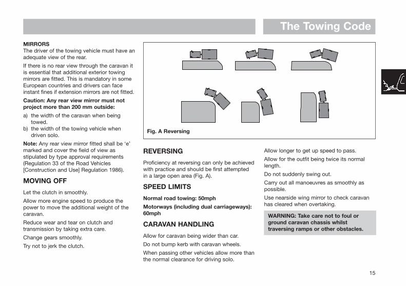
REVERSING
Proficiency at reversing can only be achievedwith practice and should be first attemptedin a large open area (Fig. A).
SPEED LIMITS
Normal road towing: 50mph
Motorways (including dual carriageways):60mph
CARAVAN HANDLING
Allow for caravan being wider than car.
Do not bump kerb with caravan wheels.
When passing other vehicles allow more thanthe normal clearance for driving solo.
Allow longer to get up speed to pass.
Allow for the outfit being twice its normallength.
Do not suddenly swing out.
Carry out all manoeuvres as smoothly aspossible.
Use nearside wing mirror to check caravanhas cleared when overtaking.
WARNING: Take care not to foul or ground caravan chassis whilst traversing ramps or other obstacles.

IMPORTANT POINTS ESPECIALLYFOR MOTORWAY DRIVING1. Caravans may not be towed in the out-
side lane of a three or four lane motor-way. (Reg. 12(2) of the Motorway Traffic [England and Wales] Regulations 1982).
2. Reduce Speed:i) In high or cross winds.ii) Downhill.iii) In poor visibility.
3. High sided vehicles cause air buffeting so extra care must be taken when passing orbeing passed. As much space as possible should be given.
CHANGING A WHEEL1. Leave caravan hitched to towing vehicle
and ensure handbrake is applied.
2. Lower corner steadies (as safety measure) on the side that the wheel is being changed to stabilise the caravan.
3. Use wheel brace to slacken off wheel nuts on the wheel to be changed.
4. Position jack under the axle at the appropriate jacking point (see fig. B)
5. Jack up the caravan until the wheel for removal is just off the ground.
6. Remove the wheel nuts, wheel trims and remove the wheel.
7. Fit spare wheel and reverse the above procedure.
Ensure clean, dry mating surfaces andclean, dry bolt/nut sealing areas.
8. Tighten all four/five nuts, according toFig. A, to 88Nm (65lb/ft) for steel wheelsor 115Nm (85lb/ft) for alloy wheels usinga torque wrench or have checked as soonas possible.
Ensure the correct wheel fixings are used,as supplied with your caravan
IMPORTANTWhen a wheel has been removed andreplaced the torque of the wheel nuts shouldbe re-checked after approximately 15 milesof running. (See 8 above).
JACKING POINTS
WARNING: Only jack up your caravan when it is coupled up to the car with its handbrake applied and in 1st gear (engine off).
Ensure that the jack is located in the correctposition, i.e. on the jacking bracket on thechassis for the Al-Ko side mounted jack(Fig.B). Alternatively the reinforced axlemounting plate can be used as an alternativebut the chassis member itself MUST NEVERbe used as a jacking point.
All caravans are provided with the facility tofit Al-Ko side jacking points and although ascissor, trolley or bottle jack may be used, it is recommended that the side mounted Al-Ko Jacking System should be used.
Fig. A Wheel Nut Tightening Fig. B Scissor Jack
The Towing Code
16

The Towing Code
17
Levelling pads or boards should be usedunder the steadies where the ground is softor uneven.
In extreme cases where it is necessary toraise a wheel off the ground for levellingpurposes, further adequate support shouldbe applied so that the steadies do not takeany undue strain.
Exterior DoorTo prevent distortion of the body, the caravanmust be always correctly sited and levelled.Failure to site the caravan correctly mayprevent the exterior door from closingproperly.
3. UnhitchingApply the caravan handbrake.
Lower the jockey wheel to the ground.
Disconnect the breakaway cable and roadlighting plugs.
Release the stabiliser by lifting the redhandle. Then lift the exposed black handleforward until it clicks up, at the same timewinding down the jockey wheel, to lift thecaravan clear of the towing vehicle.
When this operation is complete, replacetowball cover and secure the 12N+12Scables in their storage cups.
Park your vehicle alongside the caravan onthe offside.
STOPPING ON A HILLPulling off again can sometimes present aproblem. The easy solution is
(i) Carry a good sized wedge shaped piece of wood with a rope or light chain attached.
(ii) Attach the other end of the rope to the nearside rear grab handle.
(iii) Place the wood behind the nearside caravan wheel.
(iv) Carefully reverse the car slightly back down the hill, the caravan will stop against the wedge and turn.
(v) Drive forward since this attempt to move up the hill will now not involve pulling the full weight of the caravan until the car hasgained some traction.
ARRIVAL ON SITENote: Check and observe site regulations.
1. Selecting a pitchDo not pitch in such a position that youroutfit will obstruct others coming in.
Try to choose an area which is dry, reason-ably level and preferably with a hard base.
If you have no alternative but to pitch on aslope ensure that, for when you leave, youare facing down the slope.
It is good practice to chock the wheels ofthe caravan when parked on a slope eventhough the caravan brakes are applied.
2. Levelling the caravanLevelling must be carried out in bothdirections in order for the refrigerator andother equipment to function correctly. Thisshould be done before unhitching thecaravan. Levelling boards (Fig. C) can beused to raise one side of the caravan bydriving or reversing the caravan onto theboards. Apply the handbrake and chock thewheels.
The positioning of the jockey wheel can beused to help level the caravan.
Lower the corner steadies until they are infirm contact with the ground.
DO NOT use the steadies as a jack they are only a means of stabilising the caravan.
Fig. C levelling Board

SAFETYAND
SECURITY
Fire .......................................................................................... 20Notice ................................................................................... 20In Case of Fire ...................................................................... 20Dicon 300AP Smoke Alarm....................................................20Smoke Alarm......................................................................... 20Fire Extinguishers.................................................................. 21
Children ................................................................................... 21Ventilation .............................................................................. 21Security ................................................................................... 22
Caravan Theft ....................................................................... 22Chassis Number.................................................................... 22Additional Security ............................................................... 22Security Chips....................................................................... 22

Fig. A Smoke Alarm
Safety & Security
FIREImportant: Your attention is drawn to thenotice affixed inside the caravan advising onfire precaution, ventilation and what to do incase of fire.
IN CASE OF FIRE
1. Get everyone out of the caravan as quickly as possible using whichever exit isthe quickest, including windows. Do not stop to collect any personal items.
2. Raise the Alarm. Call the Fire Brigade.
3. Turn off the gas supply valve if it is safe todo so.
4. Turn off the electricity supply at supply point.
DICON 300AP SMOKE ALARMThis smoke alarm is approved for use incaravans and mobile homes. (Fig. A)
The National Caravan Council requires thatall new or used caravans sold by itsmembers be fitted with a smoke alarmfeaturing an alarm silence facility.
FEATURES
• Battery operated. No need for mains power wiring.
• Operating Light (LED)
Flashes approximately every 45 seconds confirming unit is powered.
• Low Battery WarningUnit “beeps” approximately every 45 seconds for up to 30 days when the battery needs replacing.
• Sensitivity Test ButtonTest sensitivity, circuitry, battery and horn.
• Loud 85 Decibel Piezo Electric AlarmAutomatically resets when hazardous condition has passed.
• Precise Sensitivity
• High Quality Solid State Components
CONNECTING THE BATTERY
Your alarm requires one 9 volt battery topower the smoke detector portion of theunit. Under normal use the battery powering
the smoke detector should lastapproximately one year.
WARNING: Ensure that batteries are correctly installed. Positive terminal to positive contact (marked +), negative terminal to negative contact. Reversing a battery in its compartment will immediately drain the battery and could damage the smoke alarm.
HOW TO TEST
Press test button until alarm sounds, thenrelease. Repeat test weekly.
Note: Always test smoke alarm operationafter vehicle has been in storage, before eachtrip and at least once per week during use.
20

Safety & Security
WARNING: The electronic test button provides a full test of the unit’s functionality. DO NOT try to test the alarm with a naked flame, as this may present a potential fire hazard.
FALSE ALARMS
Abnormal air conditions may cause thehighly sensitive smoke alarm to give a“false” alarm. DO NOT DISCONNECT THEBATTERIES. If no fire is apparent, ventilatethe caravan and/or blow fresh air into theunit until the alarm stops. Once cleared thesmoke alarm will automatically reset.
MAINTENANCE
Dust can lead to excess sensitivity thereforeit is recommended that the unit bevacuumed every 6 months to help keep theunit working efficiently.
Open cover and gently vacuum interior ofdetector trying to keep the nozzle fromtouching the unit.
WARNING: Never use portable cooking or heating equipment other than electricheaters that are not of the direct radiant type, as it is a fire and asphyxiation hazard.
WARNING: Appliances such as cookers must not be used for heating.
FIRE EXTINGUISHER
It is recommended that a 1kg (2lb) minimumcapacity dry powder fire extinguisher becarried inside your caravan at all times.
When using a dry powder extinguisher it issuggested that the caravan be evacuateduntil the powder has settled, to avoidinhalation.
A fat pan fire should not have a fireextinguisher aimed at it. It should besmothered with a fire blanket.
WARNING: Provide one dry powder fire extinguisher of an approved type or complying with ISO 7165, of at least 1kg capacity, by the main exterior door and a fire blanket next to the cooker. Familiarise yourself with the instructionson your fire extinguisher and the local fire precaution arrangements.
ESCAPE PATHS
It is important that you do not block escapepaths to emergency exits with obstructionsor hazards.
CHILDRENDo not leave children alone in the caravan inany event. Keep potentially dangerous itemsout of reach, as at home e.g. matches, drugsetc.
VENTILATIONAll caravans comply with BS EN 721. Theventilation points on your caravan are fixedpoints of ventilation which are required bythe European Standards.
All caravans have ventilation at high leveland low level which have been calculated tosuit the individual needs of your caravan.
High level ventilation is achieved by meansof the roof lights and washroom roofventilators. The low level ventilators arepositioned underneath the oven housing.Some models with sliding doors have twovents located underneath the sliding doors.
Under no circumstances must these ventsbe blocked or obstructed.
It is advised that fixed ventilation points arechecked and cleaned (if necessary) on aregular basis using a small brush and adomestic vacuum cleaner.
Additional night time ventilation is obtainedby releasing the window catches and placingthem in the second groove. Note thewindows are not sealed from rain in thisposition.
As the ventilation levels are calculated to suiteach models requirements there should beno modifications made which may result inreduced ventilation levels.
WARNING: Do not obstruct ventilation.
21

Safety & SecurityPetrol/Diesel FumesThe fitting of a tail pipe to your car exhaustwill reduce the possibility of fumes enteringyour caravan through the ventilation points.
Note: Never allow modification of electricalor LPG systems and appliances except byqualified persons at an authorised SwiftGroup dealership.
SECURITYCaravan theftThe theft of a caravan can occur in the mostunlikely circumstances; from a motorwayservice area, even from an owner’s driveway.
Secure all windows and doors when yourcaravan is unoccupied even if only for a shortlength of time.
Chassis numberRecord your caravan chassis number whichcan be found on the front offside section ofthe drawbar (Fig. A) or any of the eye levelwindows.
Make a note of this number in the spaceprovided at the front of this handbook andmake a separate note of the number to keepsafe at home.
Additional securityConsider fitting any device which might deteror prevent intrusion by thieves.
A hitch lock cover prevents towing of thecaravan.
A wheel lock prevents towing of the caravanand removal of the wheel.
Customers are advised to identify theircaravan with a method for subsequentidentification if other forms of identificationhave been altered or removed.
Free crime prevention advice about securingyour caravan, protecting your valuables,property marking, either at home or whilst onsite, can be obtained from the CrimePrevention Officer through your local PoliceStation.
22
Fig. A Chassis Number
SECURITY CHIPS
A special security chip is concealed withinthe body of every caravan. This chip containsthe individual identity of your caravan andcan only be read by using a special decoder.Your local police can obtain the use of adecoder by contacting C.R.I.S. on telephoneno: 01722 411430
CARAVAN INSURANCE
It is recommended that the caravan and itscontents should be insured against theft.
It is essential to check with your carinsurance company to ensure you arecovered when towing your caravan.

SERVICES
Connection of Services ......................................................... 24Water ....................................................................................... 24
Typical Water Schematic Drawing .........................................24Truma Compact Crystal 2 ......................................................25Shurflo water Pump ...............................................................25Inboard Water Tanks and On-line Water Systems.................26Truma Waterline......................................................................26Microswitch Taps ...................................................................27Comet Roma Single Lever Mixer Tap ....................................27Reich Kama Single Lever Mixer Tap ......................................28Guidance on Cleaning............................................................29
Gas ........................................................................................... 30Typical Gas Schematic Drawing ............................................30General Information................................................................31Types of Gas ..........................................................................31Gas Safety Advice..................................................................32Thermal Insulation Heating ....................................................33
Electricity ................................................................................ 34Instructions for Electricity Supply ..........................................34Overseas Connection.............................................................35Wiring of Connecting Cable and Caravan Mains Inlet...........36Typical Appliance Consumption Figures................................37

ServicesConnection of services is dealt with underthe separate headings.
In all cases users should become familiarwith the equipment manufacturers’instructions.
Advice and leaflets, if not supplied with thecaravan, can be obtained from the suppliersof the equipment.
Before making connections of anydescription to the caravan or its equipment,ensure that ALL equipment is turned off.
WATER
The caravan can use three separate systemsfor its water supply.
1. External water carrier.
2. Inboard water tank (for winter use essential).
3. Watermaster Aqua Source (mains water)or Truma Water Line.
24
Typical water schematic drawingwithout water tank (model specific)
Typical water schematic drawingwith water tank (model specific)

Services
TRUMA COMPACT CRYSTAL 2
Raise the lid, clean both the water socketand the plug of the pump assembly.
Plug the pump connector into the socket.Turn the top security clip anti-clockwise andthe bottom security clip clockwise to lockthe plug into place.
Place the pump into the water container,ensuring that it is fully submerged beforeoperating the system. A dust cover isavailable to stop contaminates falling intothe water container.
To remove the pump assembly from theCrystal Compact Housing, release thesecurity clips and pull the hose adaptor byusing the finger grips provided.
Do not remove by pulling the hose or electric cable.
When using the Winter Kit the blanking plugprovided will be fitted to the housing notbeing used.
Clean the water system at the start andend of the season with sterilising fluid(see notes under sterilising).
If the pump fails to deliver water the mostlikely cause will be air in the system. Switchoff the pump and shake the pump assemblyin the water. Then switch on again.
STERILISING
1. When cleaning the water system at the start or the end of the season it is advisable to use a sterilising fluid e.g. Chempo SDP or similar.
2. Flush the system thoroughly to remove the effective fluid traces.
3. After sterilising the system at the start of the season it is recommended that a newfilter cartridge (if fitted) should be fitted. (Not standard).
SHURFLO WATER PUMP(MODEL SPECIFIC)Fresh water is supplied to the caravan onsome models by a Shurflo pump. This pumpis a completely sealed unit designed forintermittent use and is self priming.
25
pump connection
dust cover

Services
26
INBOARD WATER TANKS ANDON-LINE WATER SYSTEMSTo fill the inboard tank from an externalcontainer follow these simple instructions:
1. Insert Truma Thames or Maxi submersiblepump into external water container.
2. Lift flap and plug pump connector intoTruma socket on side of caravan.
3. Ensure the inline stem shut off valve is inthe open position. This is located next tothe tank or T-connector feeding the tank.Ensure that where Ultrastore water heateris fitted the dump valve adjacent to this isclosed. Ensure that the tank drain valve(in front of the tank when the bed frontflap is lowered) is in the closed position.
4. Select external pump on the control panelabove the door, and switch the pump onvia the switch adjacent to the mainsfusebox. The inboard tank will now fillfrom the external tank.
5. When water starts to flow from theoverflow on the underside of the caravan,or when the external container is empty,immediately remove the pump connectorfrom the socket in the side of the caravan.Switch off the pump at the control panelor with the switch adjacent to the mainsfusebox.
6. Turning a cold tap on with the internalpump now selected at the control panelwill relieve pressure in the tank.
TRUMA WATERLINE
WARNING: It is not recommended to tow with water in the onboard or underslung water tank as this could affect stability.
WARNING: Do not under any circumstances connect your caravan to the mains water supply without the pressure reducer fitted. Damage will occur to the caravan's water system.
1. Fig. A: Connect the fitted Crystal 2 plug(1) into the water inlet socket.
2. Fig. B: Uncoil the hose and screw capadaptor (4) to the drinking water standpipe. Plug in the hose adaptor (5).
3. Turn on the mains water supply andcheck for leaks.
4. Open one of the taps and purge any airthat may be trapped in the water system.
5. To remove, make sure that the mainswater supply has been turned off, thensqueeze in the two side clips and pull freethe plug.
Fig. A
Fig. B

Services
27
MICROSWITCH TAPSThe micro switch taps are used when thewater supply is not pressurised.
When the tap is turned on the micro switch(which is fitted inside the tap) activates thepump to supply water.
OperationSwivel the tap spout (a) to the desiredposition over the sink, lift the control lever (b)to activate the pump and allow water to flowsimultaneously. To adjust the temperatureswivel the lever (c) to the left or right asshown opposite.
Note: Before commencing microswitchreplacement ensure instructions are readthrough thoroughly. The entire process canbe completed without the need to removethe tap from the worktop.
Step 3
- Remove the dome
- Remove the small screwbetween cartridge andclosure
Step 4
- Remove the snap ring(small plastic piece)
Step 5
- Remove the snap ringwith the Pipe wrench(Turn left or right)
Step 6
- Pull the cartridge out ofthe housing
- Remove the old microswitch
Before you Start1. Ensure pump is isolated.
2. Position lever in central, i.e. mixer, off location.
COMET ROMA SINGLE LEVER MIXER TAP
Required tools
- Pipe wrench
- Cross-pointscrew-driver
- Flat-bladedscrew driverinside thehandle.
Step 1
- Remove themarker cap
Step 2
- Remove thescrew fromthe controlknob
- Pull themicroswitchout of thecontrol knob
Tools
1
43
5
6
2

Services
28
Step 7
- Put in the cable fromthe new microswitch.
You need 50 mm cablelength over the top ofthe housing.
Step 8
- Insert the cartridge.
Step 9
- Refit the component parts in reversesequence.
Steps 5 to 1
REICH KAMA SINGLE LEVER MIXER TAP
Exchange of the ceramic cartridge/micro switch
1. Detach cover (1) carefully. If the cover is damaged use spare part no.: 240-059512 (red cover) and 240-059513 (blue cover).
2. Loosen screw inside the handle.
3. Detach the handle (2).
4. Turn out the rosette.
5. Turn out the brass nut with spanner.
6. Pull out theceramiccartridge (3).
7. If the cartridge isdefect:- Remove the brass
ring (4) from the top of the cartridge
- Install a new ceramic cartridge, part no.: 240-0528M
- Make sure that thecartridge is in the right position.
8. If the microswitch is defect:- Pull the wire out of
the mixer- Install a new
microswitch, part no.: 240-06220M.
9. Install ceramic cartridge, brass ring, brass nut, rosette and handle in the opposite way.
Maintenance
To prevent your singlemixer tap KAMA frombeing impacted by frost, always drain thetap in the middle position of the handle.
The middle position of the handle is markedby an arrow!
9
7
8
1
4
3
2

Services
29
GUIDANCE ON CLEANING PORTABLEWATER TANKS AND THE WATER SYSTEMIN TOURING AND MOTOR CARAVANS
The water systems, and in particular storagetanks, in caravans are susceptible tocontamination by bacteria if care is not takenwith their use and cleaning. The symptomscaused by bacterial contamination are notpurely limited to gastro-intestinal diseases,but may also manifest themselves as ear,nose, throat, eye or skin infections. It istherefore important that you carry out thefollowing procedure prior to using thecaravan each time, even if you boil or filterall water you use for drinking.
Separate Water Containers
1. All water remaining in the container should be disposed of so that the container is empty.
2. The outside of the container should be thoroughly cleansed and washed down toremove any dirt, dust or other contaminant.Water at a suitably hot temperature containing an appropriate detergent is recommended for this purpose.
3. Water should be put in the container, swirled around, then emptied out.
4. The container should then be totally filled with water containing an appropriate sterilant solution and allowed to stand forthe recommended contact time (e.g. Milton for 15 minutes).
5. The solution should be emptied from the container.
6. The opening of the container should be cleaned thoroughly with an appropriate prepared wipe impregnated with a sterilant.
7. The container should be inverted whilst stored overnight (if possible).
8. The container must be filled with mains water only and mains water only should be used for the above cleaning procedure.
9. On no account should garden hoses be used to fill water tanks.
For Systems:
1. Drain down the system (open all taps to allow air in, enabling the system to drain quickly). (See Maintenance Systems).
2. Remove any water filters fitted, and replace with a short length of hose or empty filter cartridge (this will ensure the filter is not affected by the disinfectant/ sterilant solution).
3. Fill the system by using the pump with a disinfectant/sterilant solution (check that the solution at full strength appears at all taps/showers). Allow to stand for the recommended period of time.
4. Drain the system completely.
5. Thoroughly clean the outside of all taps/connectors with a cloth soaked in
the disinfectant/sterilant.
6. Flush the system through with clean drinking water until no traces of disinfectant/sterilant can be detected at any tap.
7. Replace the filter.
Suitable sterilising chemicals are availablefrom your caravan dealer, accessory shop,chemist or home-brew shops. It is not,however, recommended to use bleach orsodium metabisulphite.
This guidance has been prepared with thekind co-operation and assistance of TheEnvironmental Health Department of TheBorough Council of King's Lynn and WestNorfolk.
WARRANTYProducts are guaranteed from the date ofpurchase against defects in materials andworkmanship. If the unit proves faulty, returnit to your supplier with proof of purchase andpurchase date. Please note that frostdamage is not a valid warranty claim.
The manufacturer retains the right to repairor replace the unit. The manufacturer cannotbe held responsible for claims arising fromincorrect installation, unauthorisedmodification or misuse of the product. Theabove does not affect your statutory rights.

Services
30
Typical gasschematic drawing

Services
31
GASGENERAL INFORMATION
Gas BottlesBottled Liquified Petroleum Gas (LPG) is themost convenient portable source of fuel foryour caravan.
Make sure that heating and cookingappliances and the gas cylinders areswitched off before you move the caravan.
Regularly check flexible gas hose, joints andconnections for tightness. Finally make surethat each gas appliance is working efficientlyto the recommendations of the appliancemanufacturers.
Only use gas bottle cylinders that are locatedwithin their dedicated position within thefront gas bottle housing, never extend hose -hose lengths must not exceed 400mm
RegulatorYour caravan is supplied with a wall mountedgas regulator plumbed inside the gas bottlecompartment. The regulator and allappliances work at a harmonised 30mbpressure, which work with Butane andPropane gas.
Pressure regulation system in this vehicle hasa fixed working pressure of 30 mbar with aflow rate of 1.5 kg/h and complies with therequirements of EN 12864 annex D.
Note: Regulator valves should always be inthe ‘OFF’ position when towing.
Gas HosesTwo new hoses, or pigtails as they are beingcalled, are available - one for Propane andone for Butane with adaptors for Butane'clip-on' and Camping Gaz cylinders. It isimportant to check you have the correct hoseand adaptor to suit your gas bottles. Push onhoses are no longer permitted under the newregulations, the new hose have threadedconnections and must be securley attachedto the regulator and to the gas bottle.
WARNING: Inspect flexible gas hose(s) regularly for deterioration and renew, as necessary, with the approved type, in any case no later than the expiration date marked on the hose(s).
WARNING: Ensure hoses do not become entangled in door mechanism.
TYPES OF GASButaneButane is supplied in the U.K. in green, blueor aluminium bottles.
All these have a male left hand threadEXCEPT for Camping Gaz which has aspecial female right hand thread and Calor7kg and 15kg and aluminium bottles whichhave a special clip-on connection.
A 7kg bottle is recommended for butanegas use.
Fig. A Gas Bottle CompartmentFig. B Gas Regulator

Services
32
Continental bottles usually have a male lefthand thread similar to but not identical withU.K. butane.
Butane is suitable for use at temperaturesdown to 2°C but will not work below that.
PropanePropane is supplied in Red, or partly redbottles which have a female left handthreaded connector.
Scandinavian countries use the sameconnector.
Germany and Austria supply propane with amale connection.
Propane will work at temperatures as low as-40°C and is therefore suitable for all wintercaravanning.
A 6kg bottle is recommended for propanegas use.
GAS SAFETY ADVICE
WARNING: If you smell gas or suspect a leak and if it is safe to do so, isolate the gas appliances and turn off the gas bottles at the regulator. Evacuate the caravan and ventilate. Seek professionaladvice as to the cause of the leak.
Facts about LPG
LPG is not poisonous.
Bi-products are harmless.
There is danger if all air and oxygen wereexcluded.
(Ventilation holes must be kept clear at alltimes).
LPG has been given a smell by themanufacturers in order to identify leaks.
Awning Spaces LPG Appliance Exhaust
There is no danger of pollution of anenclosed awning space by the LPG exhaustfrom a refrigerator venting into it, as awningspaces are generally well ventilated.
Space heaters may produce sufficientexhaust to pollute the awning space, if it istotally enclosed, from a general comfort,smell and hygiene point of view. In theextreme case there could be a build up ofcarbon dioxide to a dangerous level.
Caravan owners are advised to allow somefresh air circulation in the awning spacewhen such appliances are in use.
PRECAUTIONSa) Never look for a leak with a match.
Always use a soap solution or its equivalent when testing connections. Do not operate any electrical apparatus whatsoever, especially light switches. If the leak is not obvious, the caravan should be evacuated and qualified personnel consulted.
b) Avoid naked lights when connecting or changing a cylinder.
c) Check the flexible hose frequently.
d) The gas is heavier than air and therefore sinks to the lowest point.
e) Keep bottle gas containers outside (and protected against frost). If they must be kept inside make sure they are well away from heat.
WARNING: Do not use appliances with adifferent working pressure to 30mbar.
WARNING: Maintain adequate spacingof combustible materials from sourcesof heat.
WARNING: Do not use independentportable gas appliances inside thevehicle.
Always read individual applianceinstructions
VENTILATIONAll ventilation complies with BSEN 721 andvents should not be obstructed in anymanner as this could lead to insufficientfresh air. In this case the confinedatmosphere becomes depleted of oxygenwhich leads to the formation of the highly

Services
33
poisonous gas ‘carbon monoxide’. CarbonMonoxide is odourless, colourless andtasteless and will rapidly causeunconsciousness and death with little or nowarning prior to collapse. THERE IS NODANGER WHEN ADEQUATE VENTILATIONIS PROVIDED.
Roof-mounted Flue installationsAll flue installations should be inspectedonce a year throughout their length forcorrosion. Flues should be replaced if anysign of perforation is found. Ensure that thereplacement is of an approved type.
CONNECTIONEnsure that the gas regulator hose iscorrectly connected to the gas cylinder ingas bottle compartment and that the hoseconnection is tight.
Gas bottles must be fully located, seated atthe base of the bottles and restrained by thestrap provided in the dedicatedcompartment position.
Straps are positioned to suit 6kg and 7 kgbottles.
WARNING: If using cylinders other thanthose recommended, the user mustensure these are adequately supported,ventilation openings must not beobstructed and the cylinders must notcause damage to other fixtures andfittings located in the compartment.
Open ended gas hoses must always beprotected from dirt and insects
Before turning on the gas supply at theregulator, ensure that all gas operatedequipment in the caravan is turned off.
All gas equipment (except barbecue) issupplied through a central Gas ManifoldSystem which has individual isolation tapsfor each appliance (Fig A), as follows:
RED - Water Heater
WHITE - Space Heater
BLUE - Fridge
GREEN - Oven
YELLOW - Barbecue (if fitted)
Note: the external barbecue point is fedfrom the main feed through an isolation tap.See schematic layout for details.
THERMAL INSULATION HEATINGYour caravan has been designed to achievea thermal insulation and heating level forspecific climatic conditions when testedaccording to the procedure in EN1645-1.The classifications are as follows:
GRADE 1A caravan with an average thermaltransmittance (u) that does not exceed1.7w/(m2k).
GRADE 2A caravan with an average thermaltransmittance (u) that does not exceed1.7w/(m2k) and which can achieve anaverage temperature difference of at least20k between inside and outside temper-atures when the outside temperature is 0°C.
GRADE 3A caravan with an average thermaltransmittance (u) that does not exceed1.2w/(m2k) and which can achieve an average temperature difference of at least 35k between inside and outside temperatures when the outside temperatureis -15°C.
Fig. A

Services
34
ELECTRICITYAs with electricity in the home, care must beexercised when handling mains electricity.
Your attention is drawn to the followingnotice as laid down by the Institute ofElectrical Engineers.
INSTRUCTIONS FOR ELECTRICITYSUPPLY
On arrival at caravan site1. Before connecting the caravan installation
to the mains supply, check that
(a) both 12N & 12S plugs and hitch have been disconnected from the towing vehicle,
(b) the mains supply is suitable for your installation and appliances, i.e. whether it is a.c. or d.c. and whether it is at the correct voltage and frequency,
(c) your installation will be properly earthed. Never accept a supply from a socket outlet or plug having only two pins, or from a lighting outlet, and
(d) any residual current device (earth leakage circuit breaker) in the mains supply to the caravan has been tested within the last month.
In case of doubt, consult the site owner orhis agent.
2. MAKE SURE THAT THE SWITCH AT THE SITE SUPPLY POINT IS OFF.
3. Lift the cover of the electricity inlet provided on the caravan, and insert the connector of the supply flexible cable.
4. Remove any cover from the socket outlet provided at the site supply point, and connect the plug at the other end of the supply flexible cable to this. Switch on the main switch at the site supply point.
Note: Use mains cable fully uncoiled andprotect from traffic.
IT IS IMPORTANT THAT THE MAINSWITCH AT THE SITE SUPPLY POINTSHOULD BE SWITCHED OFF, THE SUPPLYFLEXIBLE CABLE DISCONNECTED, ANDANY COVER REPLACED ON THE SOCKETOUTLET AT THE SITE SUPPLY POINTBEFORE DISCONNECTING THE FLEXIBLECABLE FROM THE CARAVAN. IT ISDANGEROUS TO LEAVE THE SUPPLYSOCKET OR SUPPLY FLEXIBLE CABLELIVE.
Because touring caravans are generally leftunused for long periods in the open, it isstrongly advised that the mains installation isinspected periodically to ensure that it is safeto use. The IEE Wiring Regulationsrecommend that mains installations in touringcaravans are re-inspected every 3 years by aqualified person (see list) who should signand issue a periodic inspection report. (The
manufacturer recommends annualinspections).
Suitably qualified persons acceptable to theNCC to sign and issue inspection andcompletion certificates are:
• an approved contractor of the National Inspection Council for Electrical Installation Contracting* or
• a member of the Electrical Contractors’ Association
• a member of the Electrical Contractors’ Association of Scotland
• a qualified person acting on behalf of the above (in which event it should be stated for whom he is acting).
*The names and addresses of ApprovedContractors in any locality (there are over10,500 in the UK) can be obtained fromElectricity Shops, or direct from:
NICEIC, Vintage House, 37 Albert Embankment, London SE1 7UJ
Telephone: 0171 582 7746
The names and addresses of members ofthe Electrical Contractors’ Associations canbe obtained direct from:
ECA, Esca House,Palace Court, London W2 4HY
Telephone: 0171 229 1266

Services
35
ECA of Scotland, 23 Heriot RowEdinburgh EH3 6EW
Telephone: 0131 225 7221
WARNING: CURRENT CONSUMPTION IN THE CARAVAN MUST NOT EXCEED 16 AMPS OR THE PITCH PERMITTED MAXIMUM IF THIS IS LESS THAN 16 AMPS.
IT IS DANGEROUS TO ATTEMPT MODIFICATIONS AND ADDITIONS YOURSELF. LAMPHOLDER—PLUGS (BAYONET-CAP ADAPTORS) SHOULD NOT IN ANY CIRCUMSTANCES BE USED.
OVERSEAS CONNECTIONNote: Connection to a mains voltage supplyOVERSEAS requires particular attention.
Care must be taken when connectingsupplies abroad since the supplies can be ofREVERSE POLARITY.
The significance of REVERSE POLARITY isthat when equipment is switched off it maynot be electrically isolated.
The only certain way of making equipmentsafe is to unplug it.
It is useful to have a means of checkingpolarity of the mains supply, especially whentouring overseas. There are available several
proprietary makes of equipment for testingpolarity.
If it can be achieved, it is preferable toconnect live to live, and neutral to neutral tomaintain full electrical protection.
WARNING: Never allow modifications of electrical or LPG systems andappliances except by qualified persons.
WARNING: Always check the 230V supply rating on site before switching on two loads as this may cause an overload and a circuit breaker to trip.

Services
36
WIRING OF CONNECTING CABLE AND CARAVAN MAINS INLET
WARNING: IT IS ESSENTIAL THAT CONNECTIONS ARE MADE EXACTLY AS SHOWN. IF TERMINAL MARKINGS ARE NOT IN ACCORDANCE WITH THEDIAGRAM THEY MUST BE IGNORED. IF IN DOUBT CONSULT A QUALIFIED ELECTRICIAN.
THE LEGAL LENGTH OF THE MAINS INLET CABLE IS 25 ± 2 METRES. WHEN IN USE IT MUST BE FULLY UNCOILED AND PROTECTED FROM TRAFFIC.

Services
37
230 Volt 12 Volt LP GasAppliance/ Item Watts Amperes Watts Amperes grams/hour
Refrigerator 115 W 0.5 amp Only when towing 12 g/h
Ultraheat Space Heater 500 W 2.2 amp 12 W
1000 W 4.5 amp 12 W 1.0 amp 30 to 280 g/h
2000 W 8.5 amp 12 W
Ultrastore Water heater 850 W 3.7 amp Not applicable 120 g/h
Cooker Hotplate 1 Not applicable Not applicable 161 g/h
Hotplate 2 Not applicable Not applicable 110 g/h
Hotplate 3 Not applicable Not applicable 73 g/h
Hotplate 4 800 W 3.5 amp Not applicable Not applicable
Grill Not applicable Not applicable 117 g/h
Oven Not applicable Not applicable 125 g/h
Battery Charger 192 W 0.8 amp Not applicable Not applicable
Lighting 230V (based on 2x 40 W bulbs) 80 W 0.3 amp Not applicable Not applicable
Lighting 12V (based on 10 W bulb) Not applicable 10 W 0.8 amp Not applicable
Submersible water pump Not applicable 28 W 2.3 amp Not applicable
Radio/ CD player Not applicable 12 W 1.0 amp Not applicable
Omnivent position 1 Not applicable 15 W 1.2 amp Not applicable
position 2 Not applicable 30 W 2.5 amp Not applicable
position 3 Not applicable 50 W 4.0 amp Not applicable
Air Conditioning unit 715 W 3.1 amp Not applicable Not applicable
Microwave (factory fit) 1200 W 5.3 amp Not applicable Not applicable
Note: These are approximate figures for guidance only.
TYPICAL APPLIANCE CONSUMPTION FIGURES

ELECTRICALEQUIPMENT
AC50 and AC75 Control Panels ..............................................40Control Panel Operation.........................................................41
ESM 2 - Electrical Supply Module .........................................42ECM - Electrical Control Module ...........................................43ESM2000 - Electrical Supply Module ................................... 44Battery ......................................................................................46Habitation Relay ..................................................................... 46Generator Guidelines ............................................................. 46SAS 200 Mobile Alarm System................................................4712 Volt Electrical Supply ........................................................ 49Wiring of 12S Socket to Towing Vehicle .............................. 50

Electrics
40
AC50 Control Panel
AC75 Control Panel

Electrics
41
Symbol Function Description
12v Power This switch turns on (or off) the 12-volt power to all circuits. On / OFF Note: as this switch works in conjunction with a relay (that uses around 40mA to operate), it should only be used
for relatively short periods of time while using the caravan (i.e. when going out for the day).
For long-term isolation of the12 volt power, please place the Car / Van selector switch on the ESM2004 powersupply unit in the centre (Off) position (i.e. during storage).
Entry light This switch operates the internal entry light (usually the first light within the caravan).
Internal This switch turns on power to the internal water pump ready for use. It can be used to turn off the pump over Pump night to avoid any noise from the pump.
Note: A green indicator lamp will illuminate within the bottom left corner of the battery gauge when the pumpmotor is running.
External In caravans with an additional (external) pump, this switch will be a two-way switch with a centre off position. Pump This allows the selection of either the internal pump (switch up) or external pump (switch down).
Note: A green indicator lamp will illuminate within the bottom left corner of the battery gauge when the pumpmotor is running.
Battery This switch is used to display the battery voltage level. Press and hold the switch to display the battery level Level test on the gauge.
The green region indicates a battery with a good charge, the yellow region indicates a battery with an adequatecharge, and the red region indicates a battery that requires charging.
AC50 AND AC75 CONTROL PANEL OPERATION
+ -
+ -
+ -
+ -
+ -
Electrics
42
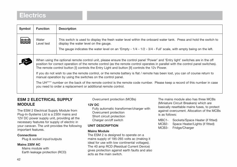
ESM 2 ELECTRICAL SUPPLYMODULEThe ESM 2 Electrical Supply Module fromPlug-In-Systems Ltd is a 230V mains and12V DC power supply unit, providing all thenecessary features for supply of electric inyour caravan. The unit provides the followingimportant features.
ConnectionsPlug & socket input/outputs
Mains 230V ACMains module withEarth leakage protection (RCD)
Overcurrent protection (MCBs)
12V DC Fully automatic transformer/charger withOvercurrent protectionShort circuit protectionCharger on/off switch
UNIT DESCRIPTION
Mains ModuleThe ESM 2 is designed to operate on amains supply of 185-265 volts ac (making itideal for use with low continental voltages).The 40 amp RCD (Residual Current Device)gives protection against earth faults and alsoacts as the main switch.
The mains module also has three MCBs(Miniature Circuit Breakers) which arebasically resettable mains fuses, to protectagainst overcurrent. Allocation of the MCBsis as follows:
MBC1- Sockets/Space Heater (if fitted)MCB2- Space Heater/Lights (if fitted)MCB3- Fridge/Charger
Symbol Function Description
Water This switch is used to display the fresh water level within the onboard water tank. Press and hold the switch to Level test display the water level on the gauge.
The gauge indicates the water level on an ‘Empty - 1/4 - 1/2 - 3/4 - Full’ scale, with empty being on the left.
When using the optional remote control unit, please ensure the control panel ‘Power’ and ‘Entry light’ switches are in the offposition for correct operation of the remote control (as the remote control operates in parallel with the control panel switches).The remote control button [I] controls the Entry Light and button [II] controls the 12v Power.
If you do not wish to use the remote control, or the remote battery is flat / remote has been lost, you can of course return tomanual operation by using the switches on the control panel.
The UH**** number on the back of the remote control is the remote code number. Please keep a record of this number in caseyou need to order a replacement or additional remote control.
+ -

Electrics
43
TRANSFORMER/CHARGERThe ESM 2 employs a fully automatic mainsto 12 volt dc transformer and batterycharger, able to operate with a wide range ofinput voltages and provide a stable outputvoltage even under load.
The unit can provide up to 12 ampsmaximum, after which it will begin to shutdown to protect itself.
To use the charger simply place the rockerswitch to the ON position, at which point itshould illuminate and charging willcommence.
ROADS LIGHTS FUSESThe fuses are located on the front bulkheadof the right hand front locker.
Fuse Ratings
1 LH ROAD 5A
2 RH ROAD 5A
3 LH INDICATOR 7.5A
4 RH INDICATOR 7.5A
5 FOG 7.5A
6 STOP 7.5A
ECM ELECTRICAL CONTROLMODULEPUMP SWITCH & INDICATORIncluded on this panel is a pump isolationswitch and pump running indicator. Thepump isolation switch is used to isolatepower to the water pump in the event of apump fault or merely as a safeguard againstunwanted pump operation. The red pumprunning indicator will light up as a warningwhen the water pump has been activated.
AUX SWITCHThis switch may be used to power anyauxiliary dc circuits the user may wish tohave added to the system.
Battery Condition MeterThis meter indicates the power remaining inyour caravan battery.
Readings should be taken as follows:
Green region - Fully charged (no charge necessary
Yellow region - Adequate charge (re-charge if desired)
Red region - Low charge(turn on charger switch to re-charge)
A car/caravan changeover switch is providedin this module and should be used in thefollowing way:
ESM2

Caravan positionWhen in this position dc power is availablefrom the caravan battery to power all 12 voltelectric circuits.If the charger is switched ONthe caravan battery will be charged up viathe charger/transformer unit.
Central positionWhen in this position with the charger switchON, power is provided to all 12 volt circuitsvia the charger/transformer only.With the charger OFF all dc circuits areisolated.
Note: The switch should be placed in thisposition when the van is being towed.
Car positionNote: First of all the towing vehicle shouldbe electrically connected to the caravan viathe 12S socket.
The switch can be placed in this positionshould the caravan battery become discharged and no mains power is available.
ELECTRICAL SUPPLY MODULEESM2000The ESM2000 Electrical Supply Module is a230 volt ac and 12 volt dc power controlunit. It provides all the necessary featuresfor control of the electrics in a caravan. Theunit provides the following features:
Mains 230V ac - MAINS MODULEwith EARTH LEAKAGE PROTECTION
OVERCURRENT PROTECTION (RCD)REVERSE POLARITY INDICATION
12 volt dc - FULLY AUTOMATICTRANSFORMER/CHARGERwith OVERCURRENT PROTECTION
SHORT CIRCUIT PROTECTION
SWITCH & FUSE MODULEwith BATTERY CHANGEOVER SWITCH
CHARGER ON/OFF SWITCH8 FUSED DC OUTPUT CIRCUITS
UNIT DESCRIPTION
Mains ModuleThe ESM2000 is designed to operate on amains supply of 207 - 253 volts ac (making itideal for use with low continental voltages).The 40 amp RCD (Residual Current Device)gives protection against earth faults and alsoacts as the main switch. The mains modulealso has three MCB's (Miniature CircuitBreakers) which are basically resettablemains fuses, to protect against overcurrent.Allocation of the MCB's is as follows:-
For Abbey, Sterling and Swift modelsMCB1 - SOCKETS/BLOWN-AIR HEATING
(if fitted)MCB2 - WATER HEATER/LIGHTS (if fitted)MCB3 - FRIDGE/CHARGER
For Bessacarr modelsMCB1 - HEATING SYSTEMMCB2 - SOCKETSMCB3 - LIGHTS/FRIDGE/CHARGER
Using a generatorWhen using a generator in conjunction withthe ESM2000 the following must beobserved, failure to do so may result indamage to the unit:
i) Always start the generator with the mainsisolator in the caravan turned off.
ii) Allow the generator to warm up for a few minutes before energising power in the caravan, as the output voltage can be higher when cold.
Electrics
44

Electrics
45
iii) Check the generator output voltage regularly to ensure it is within the specification of the ESM2000 system (i.e. 230 volts +/- 10%)
Transformer/ChargerThe ESM2000 employs a fully automaticmains to 12 volt dc transformer and batterycharger, able to operate with a wide range ofinput voltages and provide a stable outputvoltage even under load. The unit canprovide upto 12 amps maximum, after whichit will begin to shut down to protect itself.
Switch & Fuse Module
Car/Van Selector Switch
The car/caravan changeover switch providedin this module should be used in thefollowing way:
Caravan position -When in this position dc power is availablefrom the caravan battery to power all 12 voltelectric circuits.
If the charger is switched on, the caravanbattery will be charged via thecharger/transformer unit.
Central position -When in this position with the charger switchon, power is provided to all 12 volt circuitsvia the charger/transformer only.
With the charger off all dc circuits areisolated.
Note: The switch should be placed in thisposition when the van is being towed.
Car position -The switch can be placed in this positionshould the caravan battery becomedischarged and no mains power is available.
Note: First of all the towing vehicle shouldbe electrically connected to the caravan viathe 12S socket.
Charger switchWhen the caravan battery requires charging,press this switch to the on position (it shouldthen illuminate). Also ensure the SelectorSwitch is in the van position.
DC FusesEight fuses are provided in this module toprotect all dc circuits, the fuse allocation isshown below. Fuses must be replaced onlywith the specified values.
Distribution PanelsFuse 1 - Front roof lightingFuse 2 - Rear roof lightingFuse 3 - Blown-Air HeatingFuse 4 - RadioFuse 5 - 12v sockets/Hitchlight/TV ampFuse 6 - Fan circuitsFuse 7 - Water pumps/Water sensor/
Thetford toiletFuse 8 - Ignitions
For KT9/2000 BT, GP Distribution PanelsFuse 1 - Front roof lightingFuse 2 - Rear roof lightingFuse 3 - Heating SystemFuse 4 - RadioFuse 5 - 12v sockets/Hitchlight/TV ampFuse 6 - Fan circuitsFuse 7 - Water system/Thetford toiletFuse 8 - Ignitions
Note: For models fitted with central heating,there is an additional 10 amp fuse locatedbehind the ESM 2000 distribution panel.

Electrics
46
BATTERYIt is recommended that a good qualityleisure battery is always in circuit when thesystem is in use.
A deep cycling heavy duty 12v batteryshould be purchased to provide power forlights and other electrical appliances. Aproprietary brand leisure battery with an85amp capacity is recommended.
Note: 85amp batteries and above should bechecked dimensionally before purchasing, toensure fitment within the batterycompartment, as brands vary in size.
It should be remembered that batteriessuitable for the electrical demands of acaravan differ in design from those for usewith a car, and whilst the system mayoperate with a car battery it is stronglyrecommended that only a leisure typebattery, maintained in good condition isused. The battery should be kept topped upat all times.
The battery should be positioned in itscompartment, which is vented to theoutside, and be properly secured beforetravelling
WARNING: Do not block battery boxvents.
WARNING: When connecting the battery,ensure that the correct polarity is observed (black is negative and red is positive) and that the terminals are securely fastened.
Under normal circumstances it should not benecessary to remove the battery other thanfor routine inspection of terminals and“topping up”.
WARNING: Explosive gases may be present at the battery. Take care to prevent flames and sparks in the vicinity.
Your caravan has been fitted with an in-linefuse between the battery terminal and stripconnector. It is recommended that the fuserating fitted in this location does not exceed20 amps.
WARNING: Switch off all appliances and lamps before disconnecting the battery.
Smoking is prohibited around the battery compartment.
To preserve the life of your leisure batteryand charger please observe the following:
i) Do not leave all 12v lights powered at thesame time as this will drain your leisure battery more rapidly.
ii) If all 12v lights must be powered together,ensure the battery is 'in-circuit' i.e. selector switch in the 'van' position and that the battery charger is turned on.
iii) For optimum performance use the transformer/charger unit with a leisure battery attached.
SUPPORT SERVICEPLUG-IN SYSTEMS LIMITED PROVIDE ANON-CALL SERVICE FOR WARRANTY ORNON-WARRANTY REPAIRS.
IF YOU WISH TO TAKE ADVANTAGE OFTHIS SERVICE FOR PLUG-IN-SYSTEMSONLY
Telephone (01482) 652523 and ask forPRODUCT SUPPORT SERVICE.
HABITATION RELAYTo conform with European Safety Standards(EMC) all caravans have been equipped witha habitation relay.
This relay is actuated when the 12N/12Splugs are connected to the car’s sockets andthe car ignition is turned on.
The relay automatically isolates all 12Vequipment within the caravan, excluding thefridge’s 12V power supply, from the car.
GENERATOR GUIDELINES• Lack of regular servicing can be the
cause of most generator problems, gensets under 2kW are mainly dependenton engine speed for output frequency and voltage, poor or no servicing may cause the engine speed governor to run the genset engine too fast. Therefore frequency and output voltage can rise above the specification of the machine data plate i.e. 230V at 50Hz, this may

Electrics
47
cause damage to electrical/electronic equipment (such as battery chargers).
• A generator should always be run for a few minutes prior to connection with the caravan or motorhome electrics, to allow it to warm up and the output to settle to asteady level.
• The AC output of generators is often derived from an AC alternator, rectified to DC then inverted back to AC. In essence this means the output sinewave may not be very smooth and may not run sophisticated electronics efficiently. Someof the new wave of gensets are more sophisticated in their production of a sinewave output and are more suited to run electronic equipment.
• If in doubt consult your genset dealer or manufacturer for advice.
SAS 200 MOBILE ALARMSYSTEMUsing the latest microprocessor technologythe SAS200 provides all year roundprotection for your caravan.
Please read all sections of these userinstructions before attempting to operate theSAS200.
If you are unsure of any of the point, pleasecontact your local dealer or the manufacturerdirect (see point 5)
1. Operation
1.1 Arm/Disarm
The SAS200 Alarm System is armedand disarmed by pressing the buttonon the key fob remote controller.
The alarm has four modes ofoperation:
a) Disarmed
b) Fully armed with internalmovement sensor and tilt sensoractive
c) Partially set with only the tilt sensoractive
d) Partially set with only themovement sensor active.
The alarm indicates arm/disarmstatus by beeping. One beep =armed, two beeps in quicksuccession = disarmed.
To part set the alarm (modes c or d)hold down the arm button until thedesired mode has been selected:
Hold down and release after 2 longbeeps, mode (c) selected.
Hold down and release after 3 longbeeps, mode (d) selected.
Note: if the arm button is continuallyheld down the system will disarm andthen repeat the above sequence.
1.2 PIR Movement Sensor
The SAS200 Alarm System comescomplete with a 120° x 360° PassiveInfra Red movement sensor thatdetects body movement within thevehicle.
If you are leaving pets within thevehicle the system should be armedin mode (c) to prevent nuisancetriggering.
1.3 Tilt Sensor
The SAS200 Alarm System has aninbuilt tilt sensor that detects tilting ofthe vehicle during the hitchingprocess. If the tilt sensor is not setcorrectly, the alarm will not arm andwill indicate a fault by beeping 4times in rapid succession.
During normal (on the flat) operationthere is no need to alter the tiltsensor.
If the vehicle is parked on a steepslope it may be necessary to adjustthe tilt sensor. With the alarmdisarmed, while viewing themovement sensor lens, move the tiltadjustment lever forward until thegreen light illuminates. Note theposition of the lever.
Now move the lever backwards andagain note the position of the leverwhen the green light illuminates.

Set the lever mid way between thetwo positions.
Remember to return the lever to thecentre (locked) position whenreturning to 'on the flat' use.
1.4 Alarm Siren
When the alarm is triggered the sirenwill sound for 2 minutes. Followingthe 2 minute period the alarm willthen deactivate for 15 seconds thenrearm.
The alarm siren can be turned off atany point by pressing the key fobbutton. If the movement sensorcaused the alarm trigger, the alarmwill give a standard 'two beeps inquick succession' disarm indication.If the tilt sensor caused the alarmtrigger, the alarm will give 'two beepsin quick succession' followed by afurther 'two beeps in quicksuccession'.
1.5 Sleep mode
The SAS200 Alarm Systemincorporates a sleep mode thatextends battery life over a long periodof time.
If a charged leisure battery is fittedand is supplying 12 volts to the alarmsystem the alarm will operate instandard 'quick response' mode.
If the alarm is operating from theinternal alarm battery only, the alarmwill operate in 'slow response' batterysaving sleep mode. In this mode youwill need to press and hold thearm/disarm button for up to 3seconds to arm or disarm the alarm.
2. Key Fobs
The SAS200 Alarm System comescomplete with 2 key fob remotecontrollers. If an additional controller isrequired these can be ordered from yoursupplier.
2.1 Key Fob Battery Replacement
1. Remove the key fob from your keyring.
2. Prise the casing apart near the keyring fixing slot.
3. While holding the base part of thecasing, prise out the old Lithiumbattery and replace with a newCR2032 battery. Ensure the [+]terminal is located towards theouter case.
4. Relocate the two casing halfs andsnap together.
5. Refit the key fob onto your keyring.
6. Remember to dispose of oldbatteries in accordance with localregulations.
3. Battery
The SAS200 Alarm System incorporates a3.3Ah sealed lead acid battery that ischarged from the vehicles 12v supply.This battery has been selected to run thealarm without any external supply voltagefor up to 9 months depending on ambienttemperature/initial charge.
The battery is fully charged when thealarm system is despatched, but mayneed further charging if the vehicle isstood for a number of months without a12v supply to the alarm.
To charge the alarm battery either fit afully charged leisure battery to the vehicleor connect the vehicle to the mainssupply and switch on the 12vcharger/power supply.
The internal battery should be replacedapproximately every 3 years to ensurecorrect operation. Replacement batteriescan be ordered from your supplier.Always dispose of old batteries inaccordance with local regulations.
4. Specification
4.1 Control Box
Supply voltage: 10.5 to 15v DC
Supply current: 250mA max
Operating temperature: -5 to +30°C
Battery capacity: 3.3Ah at 12v
Electrics
48

Electrics
49
Operating time (armed) with 9 months no supply: at 20°C
Siren output: 110 dB +/- 10%
4.2 Movement Sensor
Range: 120° x 360° x 8M
Current consumption: <1mA typical
4.3 Key Fob
Range: >10M typical
Battery: CR2032 Lithium Cell
Typical battery life: 1 year
5. Spare Parts/Service
For spare parts, local supplier contactdetails or other service information pleasecontact:
Sargent Electrical Services Ltd.service desk on 01482 678981 duringnormal office hours.
12 VOLT ELECTRICAL SUPPLYIf your car is fitted with the appropriate relay,please note the following points:
1. The caravan battery will be charged by thecar charging system independently of thedistribution panel.
2. If the caravan battery level is “low”, power for the caravan 12 volt system canbe obtained from the car battery, by connecting the 12S (grey) plug to the car, and setting the distribution panel selectorswitch to “car”. This will draw power fromthe car battery and care should be taken not to reduce the level of the car battery so low that the car engine cannot be started. (The battery level indicator in the caravan distribution panel will show the condition of the car battery in these circumstances).
3. When the car and caravan are connected through the 12N and 12S plugs and thecar engine is running, 12 volt power will be supplied to the refrigerator, provided the refrigerator selector switch is set to the 12v position, regardless of the position of the distribution panel selector switch.
4. If an extension lead from the 12S socket on a towing vehicle to the 7-core connecting cable is used while a caravan is parked on a caravan pitch, its length should be kept to a minimum and not exceed 5 metres. The minimum cross sectional area of the supply and return leads in the extension cable should be 2.5mm2.

Electrics
50
Note:If using a combination relay, ensure the supply fuse is the correct amperage. A lower rating will ‘blow’ causing the fridge, if switched on,to be connected directly to the caravan battery. While towing, the caravan battery will be discharged instead of being charged.
WIRING OF 12S SOCKET TO TOWING VEHICLE

FITTEDEQUIPMENT
Truma Ultrastore Water Heater.............................................. 52Truma S 3002 P and S 3002 Auto Space Heater ................. 55Truma Ultraheat for S 3002 (P), S 5002 and
S 55 T Heaters .....................................................................57ALDE Heating System .............................................................59TP5 Electronic Programmable Room Thermostat ...............67Refrigerator ............................................................................. 68
Dometic RM7271L, RM7275L, RM7291L, RM7295L, RM7361L, RM7365L, RM7401 and RM7405L ................. 68
Model RM4501 ..................................................................... 80Thetford Absorber Refrigerators ............................................80
Stoves Hobs, Grills & Ovens ................................................. 90The Hob ............................................................................... 90Electric Hotplates ...................................................................91The Grill ..................................................................................91The Oven................................................................................91Cleaning .................................................................................92
Thetford Cassette Porta Potti ............................................... 94Thetford Cassette C-200 CW & C-200 CWE........................ 97
TV Inlet ................................................................................... 101External Barbeque Point ...................................................... 101Bedding ................................................................................. 102Cassette Blinds and Flyscreens ......................................... 104Doorscreen ........................................................................... 104Seitz Entrance Door ...............................................................105Roof Lights and Windows .....................................................105Air Conditioning .....................................................................106Ash Framed Doors ................................................................107Shower .................................................................................. 107Tables .....................................................................................107Fixing of Awnings ................................................................. 108
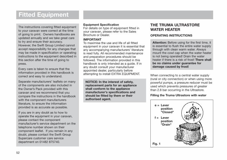
Fitted Equipment
The instructions covering fitted equipmentto your caravan were correct at the timeof going to print. Owners handbooks areupdated annually and we take great careto try and ensure their accuracy.However, the Swift Group Limited cannotaccept responsibility for any changes thatmay be made in specification or operatinginstructions to the equipment described inthis section after the time of going topress.
Every care is taken to ensure that theinformation provided in this handbook iscorrect and easy to understand.
Separate manufacturers’ leaflets on manyof the components are also included inthe Owner’s Pack provided with thiscaravan and we recommend that youcompare the instructions in the handbookwith the component manufacturersliterature, to ensure the informationprovided is as accurate as possible.
If you are in any doubt as to how tooperate the equipment in your caravan,please contact the componentmanufacturer’s service department on thetelephone number shown on theircomponent leaflet. If you remain in anydoubt, please contact the Swift GroupSupercare customer care servicedepartment on 01482 875740.
THE TRUMA ULTRASTOREWATER HEATEROPERATING INSTRUCTIONS
Attention: Before using for the first time, it is essential to flush the entire water supplythrough with clean warm water. Alwaysmount the cowl cap when the water heater is not being operated! Drain the waterheater if there is a risk of frost! There shallbe no claims under guarantee fordamage caused by frost!
When connecting to a central water supply(rural or city connection) or when using morepowerful pumps, a pressure reducer must beused which prevents pressures of greaterthan 2.8 bar occurring in the Ultrastore.
Filling the Truma Ultrastore with water
Equipment SpecificationFor details on type of equipment fitted inyour caravan, please refer to the SalesBrochure or Dealer.
IMPORTANTTo maximise the use and life of all fittedequipment in your caravan it is essential thatany accompanying manufacturers’ literatureis read fully. All recommended maintenanceand preparation procedures should befollowed. The information provided in thishandbook is only intended as a guide. If inany doubt consult your manufacturerappointed dealer, particularly beforeattempting to install EXTRA EQUIPMENT.
NOTICE: In the interest of safety, replacement parts for an appliance shall conform to the appliance manufacturer's specifications and should be fitted by them or their authorised agent.
52
e = Lever position "Closed"
f = Lever position "Drain"
Fig. 1

Fitted Equipment1. Check that the safety/drain valve in the
cold-water intake is closed. Lever should be in the horizontal position, position (e).
2. Open the hot tap in the bathroom or kitchen with pre-selecting mixing taps or single lever fittings set to hot.
3. Switch on power for water pump (main switch or pump switch). Leave the tap open to let air escape while the water heater is filling. The heater is filled when water flows out of the tap.
Residues of frozen water can prevent filling if there is a frost. The water heater can be defrosted by switching on the heater for a short period (max 2 mins). Frozen pipes can be defrosted by heating the room.
Note: If just the cold water system is beingused, without water heater, the heater tank isalso filled up with water. In order to avoiddamage through frost, the water contentsmust be drained by actuating the safety/drainvalve, also when the heater has not beenused. As an alternative, two shut-off valves,resistant to hot water, can be fitted in front ofthe cold and hot water connection.
Draining the water heater
1. Disconnect power for water pump (mainswitch or pump switch).
2. Open hot water taps in bathroom andkitchen.
3. Open safety/drain valve: Lever in verticalposition, position (f).
4. The water heater is now drained directly tothe outside via the safety/drain valve.Check that the water contents have beencompletely drained (10 litres).
Gas operating instructions
Attention: Never operate the water heaterwithout water in it!
If the wall cowl is positioned close to anopening window (or hatch) - in particulardirectly under it - it must remain closedwhen the water heater is in use (seewarning plate).
1. Remove cowl cover.
53
2. Open gas cylinder and open quick-actingvalve in the gas supply line.
3. Select required water temperature at rotaryknob (c) infinitely variable from approx. 30°to 70°c.
4. Switch on water heater at the rotary switch(a) on the control panel, green indicatorlamp "Operation" lights up.
5. If there is air in the gas supply line, it maytake up to a minute before the gas isavailable for combustion. If the applianceswitches to "Failure" during this period,switch off the appliance - wait 5 minutes -and switch on again!
a = Rotary switch "On" "Gas operation"
b = Rotary switch "Off'"
c = Rotary knob for temperatureselection (illuminated by green lamp "Operation")
d = Red indicator lamp "Failure"

Fitted EquipmentSwitching off (gas operation)
Switch off the water heater at the rotaryswitch (b).
Drain the water heater if there is a risk offrost!
If the water heater is not to be used for alonger period, mount cowl cover (non-observance of this point can lead to thefunction of the appliance being impairedthrough water, dirt or insects), close quick-acting valve in the gas supply line and closethe gas cylinder.
There shall be no claim under guarantee ifthis point is not observed.
Always remove the cowl cover prior tooperating the water heater!
Red indicator lamp "Failure"
The red indicator lamp (d) lights up if there isa failure.
The reason for such an indication is, forexample, no gas available or air in the gassupply system, triggering of the excesstemperature monitor etc. To unlock, switchoff the appliance, wait 5 minutes, and switchon again.
In event of faults, always contact theTruma Service on Tel: 01283 511092.
Electrical Operating Instructions
Switch the switch on the control panel to"On". This indicates the electrical water-heating element is operative.
When using the vehicle switches refer tooperating instructions of the vehiclemanufacturer or see switch labels.
Note: The water temperature cannot beselected, automatic temperature limitation atapprox. 70°C. For a faster heating up periodthe appliance can be simultaneouslyoperated with gas and electrical power.
Note: The water tank in the Truma-Ultrastoreis made of high quality food-proof stainlesssteel VA.
Use wine vinegar for de-scaling the watersupply. Allow the product to react and thenthoroughly flush out the appliance withplenty of fresh water. To sterilise the waterwe recommend "Certisil- Argento". Otherproducts, particularly those containingchlorine are unsuitable.
In order to avoid the proliferation of micro-organisms, heat the Ultrastore to 70° atregular intervals.
Do not use the water as drinking water!
Important Operating Notes
1. If the cowl is positioned close to an opening hatch (window), keep this closedduring operation. See warning plate. Always mount the cowl cover if the heater
is not being used. Non-observation of this point can lead to the function of the appliance being impaired through water, dirt or insects.
2. The guarantee will be invalidated if this point is not observed. Always remove thecowl cover prior to operating the water heater!
3. If there is a defect in the electronics, return the control Printed Circuit Board well padded. If you fail to pack it correctly the guarantee will be invalidated. Only use original Truma Ultrastore control P.C.B's as spare parts.
4. If just the cold water system is being used, without water heating, the header tank becomes more vulnerable to frost damage. Accordingly the contents should be drained by operating the safety/drain valve. This also applies when the motorhome is in storage.
General Safety Notes
In the event of leaks in the gas system or ifthere is a smell of gas:
• Extinguish all naked flames
• Do not smoke
• Switch off the appliance and gas cylinder
• Open the windows
• Do not operate any electrical switches
• Have the entire system checked by an expert
54

Fitted Equipment
55
1. Repair jobs are only to be carried out by an expert.
2. The following would invalidate the guarantee:a. Any alteration to the appliance
(including cowl)b. The use of non-Truma spare
parts/accessoriesc. Non observance of the operating
instructions.
3. The operating pressure for the gas supplyis 30mbar (or 28mbar butane/37mbar propane) and must correspond to the operating pressure of the appliance (see name plate).
4. Do not operate the water heater when refuelling the vehicle and when in the garage.
5. During the initial operation of a brand newappliance (or after it has not been used for some time), a certain amount of fumes, and a slight smell, may be noticedfor a short time. Remedial action is to immediately run the heater at maximum output and to ensure adequate room ventilation.
6. If the burner makes an unusual noise or ifthe flame lifts off, it is likely that the regulator is faulty and it is essential to have it checked.
Technical Data
Water contents: 10 litres
Water pressure: up to max. 2.8 bar
Type of gas: Liquid Gas (propane or butane)
Operating Pressure: 30mbar (or 28mbar butane, 37mbar propane)
Rated thermal output: 1500W
Gas consumption: 120g/h
Heating time to approx. 70°C:Gas operation: approx. 35 minsElectrical operation: approx. 70 minsGas and electrical operation: approx. 20 mins
Power consumption 12VIgnition: 0.17AHeating Up: 0.08AStandby: 0.04A
Power consumption 230VHeating Up: (3.7A) 850WWeight (empty): 6.7Kg
THE TRUMA S 3002 P & S 3002AUTO SPACE HEATERINSTRUCTIONS FOR HEATERS FITTEDWITH AUTOMATIC IGNITOR OR PIEZOIGNITOR
Switching On
1. Open the valve on the gas cylinder. Openquick-acting valve in gas supply line.
2. Turn control knob to thermostat setting 1-10 and press it down as far as the stop.At the same time keep operating the piezo ignitor rapidly until the flame ignites.
3. Keep the control knob depressed for a further 10 seconds to allow the safety pilot to operate.
4. (Piezo only) Watch through the flame window for another 10 seconds to make sure that the flame does not go out through air in the supply pipe (caused by the valve being closed or changing the cylinder).
Attention: Always wait at least 2 minutesbefore attempting to re-ignite, otherwisethere is a risk of blowbacks (misfiring).This also applies if a working heatergoes out has to be re-lit.

Fitted EquipmentAutomatic Ignitor
Prior to first ignition, make sure that thebatteries have been inserted; observe correctfit battery cassette (see changing batteries,page 57).
Thermostat
Set the required room temperature at thecontrol knob (numbers 1-10). For anaverage room temperature of approx. 22°Cwe recommend setting:
3-5 Without the Trumavent Fan (switched on)
4-8 With the Trumavent Fan
Switching Off
Set control knob to "0". If turning off for along period of time, close the quick-actingvalve in the gas supply line. Close valve ofgas cylinder.
Important Operating Notes
1. If the gas supply line is filled with air, it may take up to a minute before the gas becomes available for combustion. During this time depress the control knob and continuously operate the piezo ignitor until the flame ignites.
2. You will have to find out the exact thermostat setting yourself, depending onhow much heat you need.
3. Repairs are only to be carried out by a competent service engineer.
Attention: A new O-ring must always be installed after dismantling theexhaust duct.
4. Any alteration to the appliance (including exhaust duct and cowl) or the use of spare parts and accessories, which are important to the function of the heater and which are not original Truma parts, aswell as the non-observance of the installation and operating instructions, willlead to the cancelling of the guarantee and exclusion of liability claim.
5. During the initial operation of a brand newappliance, a certain amount of fumes anda slight smell may be noticed for a short while. Remedial action is to immediately run the heater at maximum output and to ensure adequate room ventilation.
6. In winter, before switching on the heater, remove all snow from the cowl.
7. Inspect the exhaust duct and all connections at regular intervals and always whenever there is a blowback (misfire). It is essential that the exhaust duct is installed so that it slopes upwardsover its whole length and is securely fixedwith several clamps. Never place any object on the exhaust duct, since this could result in damage. The exhaust duct connection to both the heater and the cowl must be firm and well sealed.
56
a = Control knobb = Integrated control panel for
Trumavent fan TEBc = Piezo ignitor or automatic ignitord = Flame observation windowe = Name plate (remove casing)f = Thermostat probe
In the case of left-handed installation,the parts are arranged on the other side.

Fitted Equipment
57
Do not operate heaters with incorrectly fitted or damaged exhaust ducts.
8. Never allow the warm air outlet on the heater to be obstructed in any way. For instance never hang washing on or in front of the heater to dry. Misusing your heater in this way could cause serious damage from overheating. Do not place flammable objects near the heater. Please follow these guidelines in the interest of your own safety.
9. If the burner makes an unusual noise or ifthe flame lifts off while burning, it is likely that the regulator is faulty and it is essential to have it checked.
10.Cleaning (with switched off appliance): It is recommended that at least once a year,before the heating season starts, you remove any dust that has collected on the heat exchanger base plate.
Technical Data:
Type of gas: Liquid gas (propane/butane)
Operating pressure: 30mbar (28mbar butane, 37mbar propane)
Rated thermal output: 3400W
Gas consumption: 30-280 g/h
Product Indent. No: CE-0085AP0325
Automatic Ignitor
Power consumption: 50 MA (ignition)0.01 MA (monitoring)
Operating voltage: 3V
CHANGING OF BATTERIES
Changing the Batteries on the AutomaticIgnitor
Only change the batteries with the heaterswitched off.
Always insert new batteries at the beginningof the heating season.
Remove front of heater retaining screw,located through centre of black grill. Unclipfront of heater, slide up battery cover toreveal battery. Change the batteries.Observe plus/minus.
Only use temperature resistant (+70°C), leak-proof Mignon round cells (LR 6, AA, AM 3,Art. no. 30010-23600). Other batteries couldlead to malfunctions!
TRUMA ULTRAHEATADDITIONAL ELECTRIC HEATINGFOR TRUMATIC S 3002 (P), S5002 AND S 55 T HEATERSFunction description
Truma-Ultraheat is an additional 230Velectric heater for the LPG heater modelsTrumatic S 3002/S 5002.
Heater operation is basically possible withgas only, electricity only or simultaneouslywith electricity and gas.
When using simultaneously the electrical unitwill switch itself off before overheatingoccurs as a result of the stronger gas burner.
When using electrical only we recommend toset the fan control on position 3 (manual orauto), remembering to set the output level to2000W (ensure that the fuse protection forthe power supply of the camp site issufficient).
If more than 2kw are required (heatingup/cold temperatures) you must refer backusing gas operations as the 230V electricaloperation is a secondary heater only.

Fitted Equipment
58
The electric heater can also be operatedwithout the Trumavent fans.
WARNING: Due to the design, the heaterfront case will become hot duringoperation. The operator is obliged toensure that due care is taken to protectthird parties (small children in particular).
OPERATING INSTRUCTIONS
Before operating the heater for the firsttime it is essential to observe theoperating instructions, enclosed with the heater.
Control panel with thermostat
a = Rotary switch "Off"
b = Rotary switch "On"power settings: 500 - 1000 - 2000 W
c = Rotary control knob for roomtemperature (illuminated by greenindicator lamp "operation")
Switching On
Attention: Before switching on, ensure thatthe fuse protection for the power supply ofthe campsite is sufficient for the selectedpower setting (b) (see Technical Data).
Important: The electric feed line for thecaravan must be fully unwound from thecable drum.
1. To switch on, turn the rotary switch to thedesired output level (b).
2. Set rotary control knob (c) to the desiredroom temperature.
The thermostat setting on the operatingelement (1-9) must be determinedindividually depending on the heatingrequirement and the type of vehicle. For anaverage room temperature of about 23°C,we recommend a thermostat setting of about6 -8.
The electric heater can also be operatedwithout the Trumavent fans.
If the heater is operated simultaneously withelectricity and gas, the electrical unit willswitch itself off before overheating occurs asa result of the stronger gas burner.
Switching off
Switch the heating system off at the rotaryswitch (a).
IMPORTANT OPERATING NOTES
1. Repairs may only be carried out by anexpert.
2. The heater's hot air outlet should underno circumstances be blocked. Neverhang clothes or similar in front of or ontop of the heater to dry. This could causeserious damage to the heater as a resultof overheating. Do not place inflammablematerials near the heater! Please observethese instructions for your own safety.
3. The performance of the room thermostatwill be affected if temporarily covered orobstructed
4. When operating a brand-new heater forthe first time (or after it has been idle for alengthy period) you may temporarilynotice a slight smoke and smell. Weadvise running the heater at full powerand thoroughly ventilating the room.
5. Any modifications to the appliance or theuse of spare parts and accessoriesimportant for operation which are notoriginal Truma parts, of non-observance

Fitted Equipment
59
Blown air
The air ducting outlets are generally of thebutterfly type and may be opened or closedby adjusting the butterfly valves. Twisting thedisc in its housing directs the flow in thedirection required.
One outlet on each leg of the air ductinglayout must be kept open at all times.
Switching off
Push slide switch (a) to the "OFF" position.
IMPORTANT OPERATING NOTES
1. Repairs may only be carried out by an expert.
2. Under no circumstances should the hot air outlet be blocked. Never hang clothes or similar in front of or on top of the heater to dry. This could cause serious damage to the heater as a result of overheating. Do not place inflammable materials near the heater! Please observethese instructions for your own safety.
3. When operating a brand new heater for the first time (or after it has been idle for alengthy period) you may temporarily notice a slight smoke and smell. We advise running the heater at full power and thoroughly ventilating the room
4. Any modifications to the appliance or the use of spare parts and accessories important for the operation, which are not original Truma parts, or non-observance
of the instructions for installation and usewill result in the guarantee becoming invalid and no liability will be assumed. Furthermore, the approval for operating the appliance will become invalid and in some countries also the approval for operating the vehicle.
TECHNICAL DATA
Power supply: 230 V ~, 50 Hz
Power consumption at power setting:500 W: 2,2 A 1000W: 4,5 A 2000 W: 8,5 A
Weight: approx. 2 kg
ALDE HEATING SYSTEMPlease read these instructions carefullybefore using the boiler.
These instructions are approved for AldeCompact 3000 92X, 93X and 94X boilersfitted in caravans, motor caravans andbuildings in accordance with CE no. 048 AP-0013.
A professional may only carry out installationand repairs. National regulations must beadhered to.
BOILER DESIGN
The boiler consists of three eccentricallyfitted cylinders (heat exchanger, water jacketfor the heating system and, outermost, waterjacket for hot water). The two outer pipes, aswell as their ends and connections, are madeButterfly Outlet
of the instructions for installation and usewill result in the guarantee becominginvalid and no liability will be assumed.
Furthermore the approval for operating theappliance will become invalid and in somecountries also the approval for operatingthe vehicle.
TECHNICAL DATA
Power supply: 230 V ~, 50 Hz
Power consumption at power setting:500 W: 2.2 A1000 W: 4.5 A2000 W: 8.5 A
Weight: approx 2kg
BUTTERFLY OUTLETS
The butterfly plate may be opened or closedto control the quantity of air and may also betwisted around to control direction.
For uniform distribution, outlets nearest theheater should be closed more than thosefurther away.

Fitted Equipment
60
from stainless steel, while the heatexchanger is made from aluminium.
The heat exchanger is divided into two semi-circles. The burner is located in the upperhalf, the combustion chamber, and thecombustion gases are expelled through thelower half. The burner unit is fitted on theend of the heat exchanger. It consists of acombustion fan, burner, solenoid valve andintake/exhaust connections. One or twoheating cartridges are fitted to the waterjacket of the heating system. Output is 2 or3 kW, depending on model.
DESCRIPTION OF FUNCTIONS
Using LPG
When the sliding switch on the control panelis set to LPG, the combustion fan starts.The fan creates pressure against thepressure gauge. When the fan pressure issufficiently high, the pressure gauge signalsthe electronics box that the boiler can be lit.The electronics box sends ignition sparks tothe spark plug at the same time as it sendselectricity to the solenoid valves, which opento allow gas in. The burner ignites, and asensor transmits a signal back to theelectronics box that the boiler is lit andignition spark stops. The burner keepsburning until the boiler thermostat or theroom thermostat reaches the settemperature reading. Should the boiler goout for any reason, the sensor is activated
and the electronics box ensures that a newattempt is made to start the boiler (in about10 seconds).
Using the heating cartridge
When the heating cartridge sliding switch isset to any of the output settings on thecontrol panel, the 12-volt relays on thecircuit board trip, allowing the 230-voltsupply to reach the cartridge. The heatingcartridge is controlled in the same way asthe gas boiler.
IMPORTANT INFORMATION
- The LPG boiler and heating cartridge maybe operated in parallel.
- The heating system may be heated up without the warm water heater being filledwith fresh water.
- Always drain the warm water heater of fresh water if there is a risk of frost.
- The LPG boiler must not be operated when filling the vehicle with fuel, in a garage or elsewhere.
- The boiler must not be started if there is no glycol in the system.
Note: If heating is to be operationalwhilst unattended, ensure mains hook up is connected. System can causebattery to run flat, if battery is the solepower source.
THE CONTROL PANEL
The boiler is controlled using slidingswitches on the control panel. The desiredtemperature in the vehicle is set andregulated via the thermostat on the controlpanel.
Control panel functions:
A. Heating cartridge switched off.
B. Heating cartridge switched on at 1050 W.
C. Heating cartridge switched on at 2100 W.
D. Heating cartridge switched on at 3150W (if the boiler is fitted with this output setting).
E. LPG boiler switched off.
F. LPG boiler switched on.
G. LED indicates that the LPG boiler is in blocking mode (the burner has not ignited, or has gone out for some reason).
H. Warm water setting. The circulationpump switched off. The heatingcartridge/LPG boiler is operated by theboiler's built-in thermostat. Used whenonly hot water is wanted.
I. Normal setting. The circulation pump is switched on and is controlled by the thermostat on the control panel. The operation of the heating cartridge/LPG boiler is controlled by the boiler's built-in thermostat. Used when both heating andwarm water is wanted.

Fitted Equipment
61
J. Permanent setting. The circulation pump is switched on and runs constantly. The thermostat on the control panel controls the operation of the heatingcartridge/LPG boiler. This setting is usedin particular circumstances, mostly duringthe winter. Provides an even flow of heat,but also reduces the hot water capacity.
K. Knob for setting the desired room temperature.
L. Index marking for a room temperature of approx. 22°C.
THE WARM WATER HEATER
ABOUT LPG
The properties of LPG
LPG is a petroleum product, formally knownas 'liquid petroleum gas'. It is mainly madeup of propane and butane gas. Theadvantage of propane is that it remainsgaseous at temperatures as low as -40∞,while butane loses effectiveness at +10∞C.For this reason, propane is used in coldercountries. The cylinders contain LPG both inliquid and gaseous form. Then the cylindersare filled, the pressure turns the gas intoliquid. When the cylinder valve is opened,the LPG becomes a gas again. The riskinvolved in using LPG is that any leaking gasmay ignite and explode. Since LPG isheavier than air, any leaking gas will collectat the lowest point.
LPG contains no toxic substances butbreathing in concentrated gas may have acertain anaesthetising effect, and can alsoresult in shortness of breath and symptomsof suffocation. These symptoms quicklydisappear if the sufferer breathes in ordinaryair or oxygen. Naturally, it is inadvisable toinhale either LPG or exhaust fumes. Tomake it easier to detect gas leaks, asubstance with a distinctly rank smell hasbeen added.
CombustionComplete combustion of LPG only generatescarbon dioxide (CO2) and water vapour, justlike the air we exhale. A good supply of airis essential to ensure complete combustion.The centre of the flame should beblue/green. LPG is extremelyenvironmentally compatible and does notgenerate any soot during completecombustion.It can be stored in cylinders for an unlimitedtime period, without any deterioration ofquality.PressureThe LPG burner usually works at a lowerpressure than that in the cylinder. The mostcommon pressure is a low pressure (0-50mbar), which is created by allowing the gasto pass through a reduction valve. There isalso intermediate pressure (50 mbar-2.0 bar)and, finally, high pressure (over 2.0 bar),which is unreduced pressure mainly used in
camping equipment. Low pressure andintermediate pressure are always reducedpressure.
FAULT FINDING
The boiler does not start
1. No LPG?
2. Is the main tap fully open?
3. If the boiler has not been operated for some time, or if the gas cylinder has beenchanged, it may take longer than normal to light the boiler.
4. Check that the boiler is connected to the electricity supply (> 11 V).
5. Check that the fuse (T) for the boiler is intact.
6. Check whether the overheating protectionhas been tripped by unscrewing the blackplastic cap (U) and pressing the reset button (V).
NB! If the overheating protection has been tripped it cannot be reset until the boiler has cooled down by 10-20°C. Before restarting the boiler, check that it has been properly bled.
7. Check whether the red LED on the control panel has gone out. If not, switchoff the boiler. Wait 30 seconds and then try restarting it.
8. Check that the boiler's electrical connections are properly attached.

Fitted Equipment9. If none of these help, please contact a
service company.The heating cartridge is not working
1. Check that there is an electricity supply (230 V~) to the heating cartridge.
2. Check that the relays fitted to the boiler come on (a slight click can be heard fromthe relays when the heating cartridge is switched on at the control panel).
3. Check whether the overheating protectionhas been tripped by unscrewing the blackplastic cap (U) and pressing the reset button (V).
4. If none of these work, please contact a service company.
GUARANTEE
Alde's guarantee is valid for one year fromthe date of delivery and only coversmaterials or manufacturing faults, providedthat the directions for installation and usehave been followed. The guarantee doesnot cover frost damage.
NB! Only Alde original parts should be usedas replacement parts.
The boiler is fitted with a built-in warm waterheater with a volume of approx. 8.5 litresfresh water. The warm water heater canproduce around 12 litres of 40°C water perhalf-hour (at a cold water temperature of10°C). If the heating cartridge is used insteadof gas for heating the boiler, the capacity isslightly reduced.
Always rinse out the heater before it is used,particularly if it has not been in operation forsome time.
NB! The hot water is not intended fordrinking or cooking. When the heater is incontinuous use, it should be emptiedapprox. once a month, to ensure that a newair cushion is formed in the heater. The aircushion is essential for absorbing pressuresurges in the heater.
For emptying specially adapted boilers, aswell as any other freshwater systems in thevehicle, please refer to the manufacturer'sinstructions.
NB! The warm water heater should alwaysbe drained of fresh water when there is a riskof frost and when the caravan is not in use.The guarantee does not cover frost damage.
Draining the heater using the combinedsafety/drain valve:
1. Switch off the freshwater pump.
2. Open all water taps.
3. Then open the safety/drain valve by raising the yellow lever (M) to a vertical position.
4. The heater will now drain directly below the vehicle through the safety/drain valve hose. Check that all the water is emptiedout (about 7-10 litres). Leave the valve in the open position until the next time the heater is used.
62

Fitted EquipmentNB! Check that the automatic check valve(N) is open and is allowing air to enter theheater when it is being drained, and that thehose (O) is not blocked.
THE HEATING CARTRIDGE
All compact boilers are fitted with one or two230 V heating cartridges with a maximumoutput of either 2100 or 3150 W. Select theheating cartridge output by sliding the switch
on the control panel to the desired outputposition. Always check that the input fuse ofthe vehicle has the correct amperage inrelation to the selected output.
1050 W requires a 6-amp fuse.
2100 W requires a 10-amp fuse.
3150 W requires a 16-amp fuse.
THE CIRCULATION PUMP
A 12 V circulation pump is fitted in theexpansion tank. It circulates the heatedglycol fluid in the heating system. Use thesliding switch on the control panel to startthe circulation pump. The room thermostaton the control panel controls the circulationpump, i.e. switches it on or off according tothe amount of heat required. The circulationpump may also be operated continuously.(See the control panel section.
Please note that continuous operation ofthe 12 V circulation pump considerably reduces the service life of the motor.
SYSTEM TEMPERATURE
The boiler is set to a system temperature of80°C, i.e. the temperature of the glycol fluidas it circulates in the heating system. Thesystem temperature may be reduced whenrequired, i.e. if the warm water becomes toohot.
Lowering the system temperature
Turn the spindle (Q) anti-clockwise. Aquarter turn represents a temperaturereduction of 10°C. To increase the systemtemperature, turn the axle clockwise until itreaches its maximum position and cannot beturned any further. The system temperatureis then reset to 80°C.
AIR CIRCULATION
In order to achieve the best possible resultfrom the principle of waterborne heat, it isimportant to allow air to circulate freelyunder bunks, and behind backrests andwall-mounted cabinets. If the vehicle has afitted carpet, ensure that the carpet does notobstruct the air supply to the radiators. It isjust as important that cushions or blanketsdo no interrupt the flow of air behindbackrests and wall cabinets.
63

Fitted EquipmentMAINTAINING THE HEATING SYSTEM
Winter camping
While camping during the winter, ensure thatthe flue is kept clear of snow and ice sincethe inlet air to the LPG boiler enters throughthe flue. Do not start the LPG boiler until theflue is completely free of snow. A flueextension (part no. 300 320) for fitting on theroof is recommended for winter camping.
The LPG system
A professional, who will ensure that there areno leaks from connections or hoses, shouldcheck the LPG system regularly. LPG hosesshould be changed every second year, sincetheir propensity to dry out and crack willeventually result in leaks.
To increase safety, we recommend fitting anAlde leak gauge, type 4071, as close aspossible to the pressure reduction valve.
The heating system
Regularly check the heating system's fluidlevel in the expansion tank. The level shouldbe about 1cm above the minimum indicatorin a cold tank.
The heating system should be filled with amixture of water and glycol. For preference,use high quality ready-mixed glycol (withinhibitor) intended for use in aluminiumheating systems. If using concentratedglycol, the mixture should consist of 60%water and 40% glycol. If the heating system
will be exposed to temperatures below -25°C, the glycol content must be increased,but not to more than 50%.
Any vessels used for the liquid must bespotlessly clean, and the pipes in the heatingsystem must be free of contamination. Thiswill prevent the growth of bacterial in thesystem.
The glycol mixture should be checked beforetopping up with new liquid. This will ensurethat the concentration of glycol in themixture is not too high.
If the fluid level in the expansion tank falls forreasons other than evaporation, pleasecheck all joints, drain cocks and bleederscrews to ensure that they are not leaking. Ifthe glycol-water mixture leaks out, rinse withwater and wipe up. New allow the heatingsystem to stand empty of glycol.
FILLING THE SYSTEM WITH GLYCOLFLUID
NB! Any vessels used for the liquid must bespotlessly clean, and the pipes in the heatingsystem must be free of contamination. Thiswill prevent the growth of bacterial in thesystem.
The system is filled through the expansiontank, either manually or using the Alde fillingpump which both tops up and bleeds thesystem. For manual filling, unfasten thecirculation pump nut (R) and life the pump(S) out of the tank. Slowly pour the glycol
mixture into the tank. Bleed the system.Top up with more liquid if the level has fallenafter bleeding. Bleed a newly filled systemregularly during the first days the heatingsystem is in operation.
BLEEDING THE SYSTEM
Depending on how the pipes have beenfitted, air pockets may form when thesystem is filled with glycol fluid. A sign thatthere is air trapped in the system is that theheat released into the pipes only extends ametre or so from the boiler even though the
64

Fitted Equipmentcirculation pump is operating. In newly filledsystems, small air bubbles can form in theexpansion tank, creating a murmuring sound.If the circulation pump is stopped for a fewseconds, the bubbles will disappear.
Bleeding
If a bleeder screw is fitted to the outgoingpipe on the rear of the boiler, open thisbleeder screw and leave it open until it startsto discharge water. If the boiler is fitted withan automatic bleeder, there is no need tobleed it manually.
Start the LPG boiler. The circulation pumpshould be switched off. Open the remainingbleeder screws in the system (please refer tothe instruction manual of the vehicle for theirlocations). Leave the bleeder screws openuntil they start discharging fluid. Start thecirculation pump and let it run for a while.Check that the pipes and radiators aroundthe vehicle are heating up. If they still fail toheat up, try the following:
Single-axle caravans: Stop the circulationpump. Using the jockey wheel, lower thefront of the caravan as far as possible so thatthe rear is tilted upwards. Leave it in thisposition for a few minutes to allow the air totravel upwards in the system. Open thebleeder screw at the highest point. Leave itopen until it discharges glycol fluid.
Using the jockey wheel, raise the front of thecaravan as far as possible and repeat the
procedure in this position. Then position thecaravan horizontally and start the circulationpump. Check that the pipes and radiatorsaround the vehicle are heating up.
Motor caravan or twin-axle caravan: Theeasiest way to bleed the heating system is toplace the vehicle on a sloping surface or toraise one end of the vehicle using a jack.Bleed the system as described above.
SETTINGS FOR OPERATION OF THEHEATING SYSTEM AND WARM WATERHEATER
For more information on the settings on thepanel, please refer to the 'Control Panel'section.
WARM WATER ONLY WITH 230 VHEATING CARTRIDGE
1. Switch the circulation pump switch to position (H).
2. Switch the LPG switch to position (E).
3. Switch the electric cartridge switch to position (B).
(When the system is being used for warmwater only, the electronics limit output to1kW, irrespective of the output actuallyselected).
WARM WATER ONLY WITH LPG BOILER
1. Open the LPG shut-off valve.
2. Switch the circulation pump switch to position (H).
65
A
B CD
E
FG
H
I

Fitted Equipment
66
3. Switch the LPG switch to position (F).
4. Switch the heating cartridge switch to position (A).
HEATING AND WARM WATER WITH 230 VHEATING CARTRIDGE
1. Switch the circulation pump switch to position (I).
2. Switch the LPG switch to position (E).
3. Switch the heating cartridge switch to the desired output position (B, C or D).
In the illustration, an output of 2100 W has been selected.
4. Adjust the temperature to the desired level (5-30°C) using the TPS control thermostat (K).
HEATING AND WARM WATER WITH LPGBOILER
1. Open the LPG shut-off valve.
2. Switch the circulation pump switch to position (I).
3. Switch the LPG switch to position (F).
4. Switch the heating cartridge switch to position (A).
5. Adjust the temperature to the desired level (5-30°C) using the TPS control thermostat (K).
HEATING AND WARM WATER WITH BOTH230 V HEATING CARTRIDGE AND LPGBOILER
(Use only when electricity or gas alone is notsufficient)
1. Open the LPG shut-off valve.
2. Switch the circulation pump switch to position (I).
3. Switch the LPG switch to position (F).
4. Switch the heating cartridge switch to the desired output position (B, C or D).
In the illustration, an output of 2100 W has been selected.
5. Adjust the temperature to the desired level (5-30°C) using the TPS control thermostat (K).
SETTINGS FOR OPERATION OF THEHEATING SYSTEM AND WARM WATERHEATER
For more information on the settings on thepanel, please refer to the 'Control Panel'section.
SWITCHING OFF THE LPG BOILER,HEATING CARTRIDGE AND CIRCULATIONPUMP
1. Switch all three switches on the control panel to the O-position (H, E, A).
2. Close the main switch to the heating system if the vehicle will not be used.
If the main switch is not closed, the boiler will remain in the stand-by position and use a small amount of electricity.
3. Close the LPG shut-off valve.
IF THE RED LED-LIGHT COMES ON
The boiler is fitted with an ionised flamesensor. This means that if the flame goes outfor some reason, the electronics will attemptto re-light it. If the flame is not re-lit withinten seconds, the solenoid valve switches offthe gas supply, the electronics are blockedand the red LED (G) on the control panel isswitched on. The electronics must be resetbefore the boiler can be started.
Resetting from the blocked position:
1. Switch the LPG switch to position (E). The LED (G) will go out.
2. Wait approx. 30 seconds while the electronics reset the block.
3. Switch the LPG switch to position (F). The electronics will once again attempt to start the boiler.

Fitted Equipment
TP5 ELECTRONICPROGRAMMABLE ROOMTHERMOSTATFEATURES
- Controls central heating systems to provide different room temperatures up to6 times a day
- The TP5 has one programme for Monday to Friday, with a different programme for Saturday and Sunday.
- Setting the TP5 to the lowest temperaturewill effectively switch off the heating, whilst providing frost protection for the controlled area*
RESET
The unit may be reset to 12:00PM (MO) andthe factory set programme by pressing andholding down the four buttons, temperatures and t , time + and - , until the displaygoes blank.
SETTING THE CLOCK
Press the PROGRAMME button once; thecolon is no longer flashing. Use the + and -button to set the time. Hold down a buttonto change the time quickly; press andrelease a button to change the time by oneminute. When the time and AM or PM arecorrect, press the PROGRAMME button tostart the clock, now only the day and the
colon are on display. Use + or - button toselect the correct day. Press PROGRAMMEto display the first setting.
REVIEWING THE EXISTING SETTINGSAND PROGRAMME YOUR OWN
Now each press of the PROGRAMME buttonshows, in, turn, the set times, (twelve withthe TP5), together with their associatedcontrol temperatures. The time and/ortemperature of each setting may be alteredto your own requirements using the + and -(time) and s and t (temperature) buttons.
LIMITS OF ADJUSTMENT FOR TIMESETTINGS
Time setting 1 can be at any time of the dayor night, but would normally be in themorning.
Each of the time settings 2 to 6 can be atany time between the proceeding settingand 1.59am. Time settings 2 to 5 can be setlater than the next setting, but doing thischanges the next setting as well.....E.g.changing setting 2 in any of the above to3.00pm would also change setting 3 and 4to 3.00pm.
This feature prevents times being set out ofsequence. If you wish to return to the pre-setprogramme reset the unit as describedabove.
EVERYDAY OPERATION
When all twelve time/temperature settingshave been checked and/or
altered, ensure the Programmable RoomThermostat is in the RUN mode with thecolon blinking before sliding the cover shut.
MANUAL OVERRIDE
If you wish to temporarily change the control temperature from the automatic setting, there is no need to re-programme the thermostats; just press theup or down button until the temperature you
67
12:00 PM
Set time
:MO
6:30 AM20
MOTUWETHFR
1
Set day
Setting 1
8:30 AM16
MOTUWETHFR
2
Setting 2
10:30PM16
SASU
12
Last Setting
RUN
6:30 AM19
MO

Fitted Equipmentwant is displayed. An up or down arrow willappear in the display to remind you that youhave over-ridden the programmedtemperature. The unit will revert toprogrammed temperature at the start of thenext programmed event.
CONSTANT LOW TEMPERATURECONTROL
To set the thermostat to control at its lowsetting (5°C to 16°C depending on model) for24 hours a day press both t and u buttons atthe same time. The display will show theblinking colon, the low setting and thesnowflake symbol. To return to the automaticprogramme press the t and u buttonstogether again.
BATTERY REPLACEMENT
When the batteries approach the end of their life, a battery symbol blinks in the display. Have the new batteriesunwrapped and ready, slide the battery coverfully off to the left, remove the old batteriesand insert the new ones WITHIN ONEMINUTE.
REFRIGERATORWhen using your refrigerator for the first time,it is advisable to wash the interior and itsaccessories.
When the caravan is on tow, the refrigeratorshould be operated electrically, i.e. from the12V battery in the towing vehicle, and not bymeans of bottled gas.
CONTROLSThe refrigerator can be run on either 230V,12V or LP gas. Changing between thesemodes of operation is carried out by meansof the controls shown on the relevant controlpanel.
Caution!Only use one source of energy at a time.
DOMETIC RM7271L, RM7275L,RM7291L, RM7295L, RM7361L,RM7365L, RM7401L ANDRM7405LYou have made an excellent choice inselecting the Dometic AbsorptionRefrigerator. We are sure that you will be fullysatisfied with your new appliance in allrespects.
The appliance, which works silently, meetshigh quality standards and guarantees theefficient utilisation of resources and energythroughout its entire life cycle, during manufacture, in use and when beingdisposed of.
Before you start to use the appliance, pleaseread the installation and operatinginstructions carefully.
The refrigerator is designed for installation inleisure vehicles such as caravans ormotorcaravans. The appliance has beencertified for this application in accordancewith EU Gas Directive 90/396/EEC.
WARNING AND SAFETY NOTICES
Warning: Never use a naked flame tocheck the appliance for leaks.
• Protect children!
• When disposing of the refrigerator, removeall refrigerator doors and leave the storage
68
12:00AM16
MO

Fitted Equipment
69
rack in the refrigerator. This will preventaccidental locking in or suffocation.
• If you smell gas:
- close the locking tap of the gas supplyand the valve on the cylinder.
- open the windows and leave the room.
- do not switch on anything electrical.
- extinguish naked flames.
• Never open the cooling unit; it is underhigh pressure.
• Work on the gas, flue system andelectrical components must only becarried out by qualified service personnel.
• It is imperative that the operatingpressure should correspond to the datagiven on the model plate of theappliance.
• Compare the operating pressure datagiven on the model plate with the data onthe pressure monitor of the liquid gascylinder.
• Gas operation of the appliance is notpermitted while travelling on ferries.
• Covers ensure electrical safety and mustonly be removed using a tool.
• The appliance must not be exposed torain.
• The refrigerator is not suitable for theproper storage of medications.
COOLANT
Ammonia is used as a coolant.
This is a natural compound also used inhousehold cleaning agents (1 litre of Salmiak cleaner contains up to 200g ofammonia - about twice as much as is usedin the refrigerator). Sodium chromate is usedfor corrosion protection (1.8% of thesolvent).
In the event of leakage (easily identifiablefrom the unpleasant odour):
• switch off the appliance.
• air the room thoroughly.
• inform the authorised Customer Servicedepartment.
WARRANTY AND CUSTOMER SERVICE
Warranty arrangements are in accordancewith EC Directive 44/1999/CE and thenormal conditions applicable for the countryconcerned. For warranty or other servicing,please contact our Dometic Servicedepartment. Any damage due to impro- peruse is not covered by the warranty. Thewarranty does not cover any modifications tothe appliance or the use of non-originalDometic parts;
the warranty does not apply if the installationand operating instructions are not adheredto and no liability shall be entertained. Partscan be ordered throughout Europe from ourDometic Service department. Your Service
Centre contact numbers numbers are foundin the "European Service Network" booklet
When contacting Dometic Service, pleasestate the model, product number and serialnumber together with the MLC Code, ifapplicable. You will find this information onthe data plate inside the refrigerator.
DESCRIPTION OF MODEL
Refrigerator Mobile /Mobile Absorption Refrigerator
"L" with interior light
RM 7401 L
Last digit 1 = manual energy selectionLast digit 5 = automatic and manual
energy selection
CLEANING
Before using the refrigerator, it is advisableto clean the appliance both inside and out.
• Use a soft cloth and lukewarm water witha mild detergent.
• Then rinse the appliance with clean waterand dry thoroughly.
• Remove dust from the refrigerator unit atyearly intervals using a brush or softcloth.

Warning: To avoid deterioration ofmaterials:
• Do not use soap or hard, abrasive orsoda-based cleaning agents.
• Do not allow the door seal to comeinto contact with oil or grease.
Using the refrigerator• The cooling unit is silent in operation.
• When the appliance is first put intooperation, there may be a mild odourwhich will disappear after a few hours.
• Ensure the living area is well ventilated.
• The refrigerator will take several hours toreach its operating temperature in thecooling compartment
• The freezer compartment should be coldabout one hour after switching on therefrigerator.
ControlsA. Manual energy selection MES (e.g. RM
7XX1 L)
B. Automatic and manual energy selectionAES ( e.g. RM 7XX5 L)
Note: The refrigerator is equipped to operateon mains power, DC or liquid gas (propane/butane). The desired power option isselected by means of energy selector switch(A). Energy selector switch (A) has foursettings: AC mains power, DC (12V), Gas(liquid gas), OFF.
Appliances with automatic energy selectionhave the additional setting "AUTO" .
MANUAL ENERGY SELECTION
ELECTRICAL OPERATION
12V - operation (DC)
Warning: The refrigerator should only be used while the motor is running,otherwise the on-board-battery wouldbe discharged within a few hours!
1. Set energy selector switch (A) to 12V .
2. Operating display "C", 12V lights "green".
Appliance is in function.
3. Use rotary switch (B) to regulate thetemperature in the main refrigerator compartment.
Fitted Equipment
70
A = energy selection switchB = gas/electric thermostat AC/DCC = operating displays (3 LEDs)
A = energy selection switchB = gas/electric thermostat AC/DCC = operating displays (4 LEDs)D = temperature setting displayE = dimmer for LED-displays
(only accessible when door opens)
GasAC mains power12V DCAutomatic energy selection
OFF

Fitted EquipmentNote: If the operating display fails to light up( it lights up "red" at AES models ) the deviceis not in operation. (For troubleshooting seepage 77).
Mains power
This option should only be selected wherethe supply voltage of the connection forpower supply corresponds to the valuespecified on the data plate. Any difference invalues may result in damage the appliance.
1. Set energy selector switch (A) to 230V .
2. Operating display "C", 230V lights"green".
Appliance is in function.
3. Use rotary switch (B) to regulate thetemperature in the main refrigeratorcompartment.
Note: If the operating display fails to light up( it lights up "red" at AES models ) the deviceis not in operation. (For troubleshooting seepage 78)
GAS OPERATION
• The refrigerator should only be operatedusing liquid gas (propane, butane). Do notuse town gas or natural gas.
• If the refrigerator is operated during travelusing gas, the precautions stipulated bythe legislation in the respective countrymust be taken (in conformity with theEuropean standard EN 732).
• Operating the refrigerator with gas is notpermitted during travel in France andAustralia.
• As a basic rule, operation using gas isprohibited in petrol stations.
1. Open the valve of the gas cylinder
2. Open the shut-off valve to the gas supply.
1. Set energy selector switch (A) to gas
2. Set rotary switch (B) to "MAX" position.
The ignition process is activatedautomatically, accompanied by a tickingsound approx. 30 sec. Upon successfulignition, the display LED (C) "Gas" lightsyellow.The refrigerator is in function. Userotary switch (B) to regulate the temperaturein the main refrigerator compartment.
GAS FAULTS
In the event of a gas fault (e.g. gas cylinderempty), the operating display (C) flashesyellow.
Remedies:
Set the energy selector switch (A) toposition "OFF".
1. Is there any gas in the gas bottle?
2. Is the gas bottle valve open?
3. Is the on-board shut-off valve open?
4. Set the main switch (A) to "on"
The reignition starts again.
71

Fitted EquipmentIf after about 30 seconds the operatingdisplay (C) starts flashing red again, thegas fault has not been cleared (e.g. air inthe gas pipe).
5. Briefly switch the refrigerator off and thenon again using main switch (A).
To remove air from the gas pipes, repeatthis procedure 3-4 times.
If these actions do not help, please call anauthorised Dometic Service Centre.
AUTOMATIC ENERGY SELECTION (ONLYWITH RM 7XX5 L)
"AUTO"-OPERATION
RM7XX5 L - models are equipped with an"AUTO"-MATIC function.
1. Set energy selection switch (A) to position"AUTO" .
The LED "AUTO" illuminates.
Note: Manual operation is possible at anytime.
Explanations
Upon switching on, the electronicsautomatically select one of the threepossible energy types: 230V - 12V - liquidgas. The control electronics
automatically ensure that the refrigerator issupplied with the optimum source of energyin each respective case.
Priority 1.) Solar (12V DC)2.) 230V AC3.) 12V DC 4.) Liquid gas
The selected energy is displayed by thecorresponding LED (i.e. 230V).
230 V - operation
If sufficient supply voltage is available (morethan 200V), this power source is selected asthe first option ( no solar-system installed).
12 V - operation
12V operation should only be selected whilethe vehicle motor is running or there issufficient voltage available from the solar
system. This can be detected from the D+connection of the alternator to theelectronics, or from the respective signal onthe solar charge regulator.
GAS OPERATION
Gas operation is selected in the followingcircumstances:
• No supply voltage available.
• The vehicle engine is not running.
• Supply voltage less than 200V
Refuelling Stop
In order to prevent unintended switching togas operation during refuelling, the electronicsystem starts gas operation of therefrigerator, after the motor has been turnedoff for 15 mins. During this time theappliance is in stand-by operation mode andonly the "AUTO" LED lights up.
The use of naked flames is prohibited inpetrol station environments. If therefuelling stop lasts longer than 15 mins.,the refrigerator should be switched off atthe main switch (A), or switched over toanother energy type.
72

Fitted Equipment
73
Gas faults at "AUTO"- mode
If gas faults occur the operating LED "C"flashes yellow.
Remedies:
Set the energy selector switch (A) to position"OFF".
1. Is there any gas in the gas bottle?
2. Is the gas bottle valve open?
3. Is the on-board shut-off valve open?
4. Set the main switch (A) to "on"
The ignition starts again.
If after about 30 seconds the operatingdisplay (C) starts flashing red again, thegas fault has not been cleared (e.g. air inthe gas pipe).
5. Briefly switch the refrigerator off and thenon again using main switch (A).
To remove air from the gas pipes, repeatthis procedure 3-4 times.
If these actions do not help, please call anauthorised Dometic Service Centre.
Additional functions (RM 7XX5 L - modelsonly)
• Temperature setting display (D) with 4LED to indicate the selected temperature(MIN - MAX)
• LED - dimmer (E) for adjusting thebrightness of the display-LED (onlyaccessible when door opens)
Underneath the fascia is a knurled knob foradjusting the brightness (see item E above)
Temperature setting cooling compartment
As shown, you are able to regulate thetemperature of the cooling compartment, ifnecessary, by turning rotary knob (B) .
The cooling unit’s performance is influencedby ambient temperatures.
Tip: Please select the medium setting forambient temperatures between +15°C and+25°C. The unit operates within its optimumperformance range.
STORING FOOD
• Always store food in sealed containers,aluminium foil or similar.
• Never put hot food into the refrigerator,always let it cool down first.
• Products that could emit volatile,flammable gases must not be stored inthe refrigerator.
• Store quickly perishable foods directlynext to the cooling fins.
The freezer compartment is suitable formaking ice cubes and for short-term storageof frozen food. It is not suitable as a meansof freezing foods.

Fitted EquipmentMAKING ICE CUBES
Ice cubes are best frozen overnight. At night,the refrigerator has less work to do and theunit has more reserves.
1. Fill the ice cube tray with drinking water.Only use drinking water!
2. Place the ice cube tray in the freezer compartment.
DEFROSTING
As time goes by, frost builds up on the fins.
When the layer of frost is about 3mm thick,the refrigerator should be defrosted.
1. Switch off the refrigerator, as describedon page 74 - "Switching off".
2. Remove the ice cube tray and food.
3. Leave the refrigerator door open.
4. After defrosting (freezer compartment andfins free of frost), wipe the cabinet drywith a cloth.
5. Use a cloth to mop up the water from thefreezer compartment.
6. Switch the refrigerator back on again.
Warning: The layer of ice must never beremoved forcibly, nor may defrosting beaccelerated using a heat source.
Note: Water thawing in the maincompartment of the refrigerator runs into anappropriate container at the back of therefrigerator. From there, the waterevaporates.
POSITIONING THE STORAGE RACK
Dismantling:
1. Loosen the front and back securing brackets.
2. Move the storage rack to the left and remove it.
To fit the storage rack, the reverse orderapplies.
DOOR LOCKING
Open
Close
Park-position/ vent-position
SWITCHING OFF
1. Set energy selector switch (A) to position"0" (OFF). The appliance is now fullyswitched off.
2. Secure the door open by means of the door stop. The door will be slightly ajar. This is to prevent mould from forming inside the appliance.
74
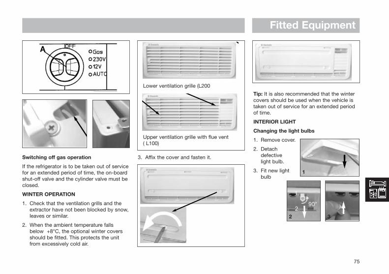
Fitted Equipment
75
Switching off gas operation
If the refrigerator is to be taken out of servicefor an extended period of time, the on-boardshut-off valve and the cylinder valve must beclosed.
WINTER OPERATION
1. Check that the ventilation grills and theextractor have not been blocked by snow,leaves or similar.
2. When the ambient temperature fallsbelow +8°C, the optional winter coversshould be fitted. This protects the unitfrom excessively cold air.
3. Affix the cover and fasten it.
Tip: It is also recommended that the wintercovers should be used when the vehicle istaken out of service for an extended periodof time.
INTERIOR LIGHT
Changing the light bulbs
1. Remove cover.
2. Detach defective light bulb.
3. Fit new light bulb
Lower ventilation grille (L200
Upper ventilation grille with flue vent ( L100)
1
2 3

Fitted Equipment4. Clip the cover
back in place.
Note: For 12V DC : 1 light bulb 12V, 2W
Please contact Dometic Service Centres forreplacement light bulbs.
CHANGING THE DECOR PANEL
1. Open the door and loosen the hinge screw.
2. Take off the door by moving it upwards.
3. Unscrew the door strip (3 screws).
4. Remove the decor plate and insert a newdecor plate.
5. Screw the door strip back in position.
6. Put the door back on.
7. Tighten the hinge screw.
Dimensions of the panels in mm:
Model Height Width Thickness
RM 7271 /..75 713+/-1 453.5+/-1 3.2RM 7361 /..65 713+/-1 453.5+/-1 3.2RM 7291 /..95 718+/-1 491.5+/-1 3.2RM 7401 /..05 718+/-1 491.5+/-1 3.2
Changing the doorhang
It is not always possible to change the doorwhen the refrigerator is installed.
1. Open the door, unscrew the hinge screw and keep it to hand.
2. Take off the door by moving it upwards.
5. Attach the door.
8. Screw the hinge screw back in
76
4
1 2
3 4
5
7
6

Fitted Equipment
77
TROUBLESHOOTING
Before calling the authorised Service Department, please checkwhether:
1. The instructions in the section "Using the refrigerator" have beenfollowed.
2. The refrigerator is not tilted excessively.
3. It is possible to operate the refrigerator with an available powersource
Note: The Seven Series refrigerator requires a constant 12 voltsupply for the fridge to operate on gas. Disconnecting the leisurebattery will switch off the gas operation of the fridge.
1 2
3
5
6 7
84
Failure : The refrigerator does not work in gas operation mode
Possible cause Action you can take
Gas bottle empty
Is the supply cut-out deviceopen?
Air in the gas pipe?
Change gas bottle
Open the cut-out device
Switch device off and on again3-4 times to remove air from thegas pipe
Failure : The refrigerator does not work on 12V
Possible cause Action you can take
On-board fuse defective
On-board battery discharged
Engine not running
Fit new fuse
Check battery, charge it
Start engine

Fitted Equipment
78
Failure : The refrigerator does not work on 230V
Possible cause Action you can take
On-board fuse defective.
No connection to supply voltage.
AES: gas operation despite connectionto the supply voltage?
Fit new fuse.
Establish power connection.
Appliance switches to gas operation due toinsufficient supply voltage (automaticallyswitches back to 230 V operation)
Failure : The refrigerator does not cool sufficiently
Possible cause Action you can take
Inadequate ventilation to the unit.
The thermostat setting is too low.
There is too much ice on the condenser.
Too much warm food put inside.
Appliance running for a short time.
Check that the ventilation grilles are notcovered.
Turn the thermostat to a higher setting.
Check that the refrigerator door sealswhen shut.
Let food cool down first.
Wait several hours, check again.
MAINTENANCE
• Works on gas components and electricalinstallation may only be carried out byauthorised personnel. We recommend tocontact your Dometic Service Centre.
• EN 1949 stipulates that the appliance´sgas equipment and it’s associated fumesystem must be inspected afterinstallation and a certificate issued.
Afterwards a qualified technician mustinspect according to EN 1949 every twoyears and a certificate issued.
It is the user’s responsibly to arrangefor inspections after purchase.
• It is recommended that the gas burner beinspected and cleaned as necessary at least once a year.
• We recommend maintenance following anextended shutdown of the vehicle.
PRODUCT LIABILITY
Product liability of Dometic GmbH does notinclude damages which may arise from faulty operation, improper alterations orintervention in the equipment, adverse effectsfrom the environment such as changes intemperature and air humidity, which may impact the equipment itself or the directvicinity of the equipment or persons in the area.

Fitted Equipment
79
ENVIRONMENTAL HINTS
Refrigerators manufactured by DometicGmbH are CFC-free.
Ammonia (a natural compound of hydrogenand nitrogen) is used in the cooling unit as acoolant. The non-ozone-hazardouscyclopentan is used as a propellant in themanufacture of the PU foam insulation.
DISPOSAL
In order to ensure that the recyclablepackaging materials are re-used, theseshould be sent to the usual local collectionsystem.
The appliance should be transferred to asuitable waste disposal company that willensure re-use of the recyclable componentsand proper disposal of the rest.
For eco-friendly draining of the coolant fromall absorber refrigeration units, a suitabledisposal plant should be used.
ENERGY-SAVING TIPS
• At an average ambient temperature ofapprox. 25°C, it is sufficient to operatethe refrigerator at the middle thermostatsetting (for both gas and mains voltage).
• Where possible, always store goods thathave previously been cooled.
• Do not position the refrigerator in directsunlight.
• Constant circulation of air must besupplied to the refrigerator unit.
• Defrost regularly.
• Open the door only for a short time whenremoving goods from the refrigerator.
• Run the refrigerator for about 12 hoursbefore filling it.
TECHNICAL DATA
Model Dimensions Gross capacity Usable Connection *Consumption Netweight Ignition SteppedH x W x D (mm) incl. freezer capacity of Mains / Battery electricity / gas Burn Control cabinetdepth incl. door compartment freezer in 24 hrs Device /
compartment Ignition unit
RM7271L 821x586cx541 77 litre 9.5 litre 125 W / 120 W ca.2.5 KWh / 260g 26kg 3 3
RM7275L 821x586cx541 77 litre 9.5 litre 125 W / 120 W ca.2.5 KWh / 260g 26kg 3 3
RM7291L 821x525cx541 86 litre 10.5 litre 125 W / 120 W ca.2.6 KWh / 260g 26kg 3 3
RM7295L 821x525cx541 86 litre 10.5 litre 125 W / 120 W ca.2.6 KWh / 260g 26kg 3 3
RM7361L 821x586cx541 88 litre 9.5 litre 135 W / 130 W ca.2.6 KWh / 260g 26kg 3
RM7365L 821x586cx541 88 litre 9.5 litre 135 W / 130 W ca.2.6 KWh / 260g 26kg 3
RM7401L 821x525cx541 97 litre 10.5 litre 135 W / 130 W ca.2.6 KWh / 260g 26kg 3
RM7405L 821x525cx541 97 litre 10.5 litre 135 W / 130 W ca.2.6 KWh / 260g 26kg 3
We reserve the right to make technical changes.*Average consumption measured at an average ambient temperature of 25°C in pursuance of ISO Standard.

Fitted Equipment
80
MODEL RM4501The refrigerator can be run on 230V, 12 V or LP gas. Changing between these modesof operation is carried out by means of thecontrol buttons positioned as shown in fig. C.
The energy selection (A) can be set at either"AC" (230V), "DC" (12 V), "GAS" (LP gas) or"OFF".
An indicator lamp (B) at the control panelflashes when the automatic ignitor attemptsto light the burner. Otherwise this lamp isoff.
The refrigerator is fitted with a safety device,which automatically shuts off the supply ofgas if the flame goes out. The safety devicecan be opened manually be depressing knob(C).
The refrigerator temperature is controlled bya thermostat (D) when the refrigerator runson 230V and LP gas. Please note that the
thermostat has no "off" position when therefrigerator runs on LP gas.
STARTING THE REFRIGERATOR
LP Gas operation
After initial installation, servicing, or changinggas cylinders etc., the gas pipes maycontain some air, which should be allowed toescape by briefly turning on the refrigeratoror other appliances. This will ensure that theflame lights immediately.
To start gas operation:
1. Open the shut off valve of the gas bottle (check that there is enough gas). Open any on-board shut-off valve.
2. Set the thermostat knob (D) to the highest setting.
3. Turn the energy selector (A) to position "GAS". A ticking sound will be heard andthe lamp (B) will start flashing.
4. Press the button (C). This opens the flame failure device and allows gas to flow to the burner.
5. When the flame lights, the sparking stopsautomatically and the lamp stops flashing.
6. Keep the knob (C) depressed for another 10-15 seconds to activate the flame failure device, then release it.
If the lamp starts flashing again, repeat steps4-6.
To terminate gas operation, turn the knob (A)to "OFF" position.
230V operation
Before taking the refrigerator into operation,check that the voltage stated on the dataplate is the same as the main voltage in use.
• Turn the thermostat knob (D) to its highest (coldest) position.
• Set the energy selector (A) to position "AC"
12 V operation
Only operate your refrigerator on 12 V whenthe engine of the vehicle is running - other-wise your battery will soon be discharged.
• Set the energy selector (A) to position "DC"
REGULATING THE TEMPERATURE
It will take a few hours for the refrigerator toreach normal operating temperature. Wetherefore suggest you start it well in advanceof a trip and if possible store it with pre-cooled foodstuffs.
On 230V operation and LP gas operation therefrigerator is controlled by a thermostat andthe thermostat knob (D) should be set at 3-5.If a lower (colder) temperature is desired, setthe thermostat to a higher figure.
On 12 V operation the refrigerator workscontinuously.
Fig. C Control Panel - RM4501 Manual Ignition
A B C D

Fitted Equipment
81
THETFORD ABSORBERREFRIGERATORSThis user’s information is for all N80 modelsof Thetford absorber refrigerators. It explainshow to use your refrigerator correctly andsafely. Read the manual carefully beforeusing the refrigerator for the first time toobtain a quick overview of how to operateand use the refrigerator.
Thetford absorber refrigerators are speciallydesigned to store fresh and frozen food andmake ice cubes in caravans and campers.The control panel allows you to select thepreferred energy source. Different energysources allow you to use your refrigeratorunder different conditions.
Thetford absorber refrigerators belong tocategory C11: gas appliances that must beinstalled so that they are isolated from theliving space.
To find out more about how your absorberrefrigerator works, visit our website atwww.thetford-europe.com .
PRECAUTIONS AND SAFETYINSTRUCTIONS
Alerts
The following alerts are used in this user’smanual:
Warning! “Warning” alerts the user to thedanger of damage to the
product or to the user if the userfails to carry out the describedprocedures carefully. Non-observance of the proceduresmay result in serious injury tothe user or damage to theproduct.
Caution! “Caution” alerts the user to thepossibility of damage to theproduct if the user fails to carryout the described procedurescarefully.
Important! “Important” denotessupplementary information forthe user and alerts the user topotential problems.
Tip! “Tip” provides the user withsuggestions and advice forcarrying out certain actions moreeasily or handily.
Warnings
• This refrigerator must be installedaccording to the manufacturer’sinstructions and in compliance with localand national regulations.
• Read this manual carefully before youstart to use your refrigerator.
• Always consult the warnings before youperform any maintenance or gas checks.
Repairs/maintenance
• Never open or damage the coolingsystem. The cooling system is pressurisedand contains substances harmful tohealth.
• Never attempt to repair gas, extractor orelectrical parts yourself. They must berepaired by a qualified service engineer.Contact the Customer Service departmentof Thetford for a list of qualified parties.
• Always switch off the refrigerator beforeyou perform any kind of maintenance orcleaning.
Use
• Never cover the ventilation gratings in thewalls of a caravan. Good ventilation isessential for the correct working of theabsorber system.
• Never expose the refrigerator to rain.
• Never operate the refrigerator by gaswhile driving. If a road accident results infire, there is a risk of explosion.
What to do if...
• You smell gas:
- close the valve of the gas bottle;
- extinguish any naked flames;
- do not switch on any electrical devicesor lighting;

- open the windows and leave the room;
- contact the Customer Servicedepartment of Thetford.
• You suspect a leak in the cooling system:
- switch off the refrigerator;
- extinguish any naked flames;
- provide sufficient ventilation;
- contact the Customer Servicedepartment of Thetford.
ABOUT YOUR REFRIGERATOR
Your refrigerator has a cold space and afreezer compartment. After starting up therefrigerator, allow it to cool for at least eighthours before placing any food in it.
Cold space
The condenser is located on the inside ofyour refrigerator. The absorber system usesthe condenser to draw off heat from therefrigerator. Therefore, never place plastic orpaper over the condenser. Air must be ableto circulate freely through the refrigerator sothat heat can be extracted.
Important! Do not cover the condenser atthe back of the refrigerator with plastic orpaper. The refrigerator cools optimally whenair is allowed to move freely through therefrigerator.
• To limit frosting on the condenser:
- always cover liquid foods before placingthem in the refrigerator;
- always let hot food cool before placingit in the refrigerator;
- never keep the refrigerator open longerthan necessary.
Fitting racks
Inside your refrigerator there are two or threestorage racks. You can adjust the racks to aconvenient height by means of a simple clicksystem:
• click the plastic bracket to the right shortside of the rack;
• turn the bracket into the horizontalposition and insert the rack tipped in asloping position into the refrigerator;
• place the short side without bracket intoone of the grooves on the left wall of therefrigerator;
• place the short side with bracket in thecorresponding groove on the right wall ofthe refrigerator;
• turn the bracket downwards to fix it intothe groove.
To move a rack, turn the bracket upwardsand remove the rack. Place the rack at therequired height in the way described above.
Securing products for driving
One of the racks in your refrigerator has asystem for securing products for driving. Thesystem consists of a simple click-and-slideplastic strip. To secure products on the rackwhile driving, push the plastic strip as tightlyas you can against the products on the rack.
In the storage space on the inside of therefrigerator door, there is the unique Thetfordflexible bottle slide. The slide prevents bottlesfrom sliding around during driving. Push theslide against the products in the door orplace the products between the bottle slide.
Fitted Equipment
82

Fitted Equipment
83
Freezer compartment
The two-star freezer compartment (N80) issuitable for making ice cubes and for storingfrozen foods for a short time.
Important!
- The freezer compartment is unsuitableas a means of freezing food.
- Use only drinking water to make icecubes.
- Do not place any other products in thefreezer compartment when you aremaking ice cubes.
- Water freezes fastest with the thermostatat the highest setting.
Tip!
- Make ice cubes at night when yourrefrigerator has more spare capacity.
Door locking mechanism
The refrigerator door has an automaticlocking mechanism. The door locksautomatically when you press it shut firmly.The lock releases unnoticed when you openthe refrigerator with your hand. Thisautomatic locking mechanism also keeps therefrigerator door shut during driving. Forsome models an additional security device isfitted below the refrigerator. By pushing thelocking bar over the closed refrigerator door
you can make doubly sure that the doordoes not come open during your journey.
If you are not going to use the refrigerator fora prolonged period of time, you can use thespecial hook of the door locking mechanismto prevent odours. Turn the hook a quarter ofone rotation to position it at right-angles tothe refrigerator. In this position, the hookprevents the door from closing.
Technical data
Category: C11
AC: 230V (50/60 Hz)
DC: 12V
Gas types: I3+ (28-30/G3: 37mbar) (Countries: BE,FR, IE, LU, PT, GB, GR,IT)
I3B/P (G30/G31: 28-30 mbar) (Countries: DK, DE, IS, NL, SE, FI, NO)
(G30 = butane, G31 = propane)
Model: N80 x Exxx
DimensionsH x W x D (mm)Depth incl. door: 821 x 525 x 543
Gross volumeincl. Freezer (L): 80
Net volumeincl. Freezer (L): 75
Volume freezer (L): 9.5
Input * (kWh/24h): 2.5
Input * (gr./24h): 238
Net weight (kg): 23
Ignition: Electrical
*average energy consumption at ambienttemperature of 25°
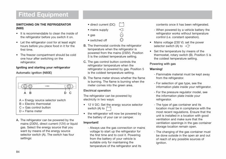
SWITCHING ON THE REFRIGERATOR(N80)
• It is recommendable to clean the inside ofthe refrigerator before you switch it on.
• Let the refrigerator cool for at least eighthours before you place food in it for thefirst time.
• The freezer compartment should be coldone hour after switching on therefrigerator.
Igniting and starting your refrigerator
Automatic ignition (N80E)
A. The refrigerator can be powered by themains (230V), direct current (12V) or liquidgas. Select the energy source that youwant by means of the energy sourceselector switch (A). The switch has foursettings:
• direct current (DC)
• mains supply
• gas
• switched off
B. The thermostat controls the refrigeratortemperature when the refrigerator ispowered from the mains (230V). Position5 is the coldest temperature setting.
C. The gas control button controls therefrigerator temperature when therefrigerator is powered by gas. Position 5is the coldest temperature setting.
D. The flame meter shows whether the flameis burning. The flame is burning when themeter comes into the green area.
Electrical operation
The refrigerator can be powered byelectricity in two ways:
• 12 V DC: Set the energy source selectorswitch (A) to
• the refrigerator will now be powered bythe battery of your car or camper.
Important!
- Always use the gas connection or mainsvoltage to start up the refrigerator forthe first time and to cool it. Poweringfrom the battery of your vehicle issuitable only for maintaining thetemperature of the refrigerator and its
contents once it has been refrigerated.
- When powered by a vehicle battery therefrigerator works without temperaturecontrol (i.e. constant operation).
• Mains voltage (230 V): set the powerselector switch (A) to
• Set the temperature by means of thethermostat, rotary switch (B). Position 5 isthe coldest temperature setting.
Powering with gas
Warning!
- Flammable material must be kept awayfrom the refrigerator.
- For selection of gas type, see theinformation plate inside your refrigerator.
- For the pressure regulator model, seethe information plate inside yourrefrigerator.
- The type of gas container and itslocation must be in compliance with themost recent regulations. Ensure that theunit is installed in a location with goodventilation and make sure that theventilation openings in the gas containerstorage location remain open.
- The changing of the gas container mustbe done outside in the open air and outof reach of any possible sources ofignition.
Fitted Equipment
84
A = Energy source selector switch B = Electric thermostatC = Gas control button D = Flame meter
A B D C

Fitted Equipment
85
- It is prohibited to use gas to power therefrigerator while you are driving. If aroad accident results in fire, there is adanger of explosion.
- It is prohibited to use gas to power therefrigerator in the vicinity of petrolstations.
1. Open the valve of the gas bottle and thegas taps.
2. Set the gas control button to the 5thposition.
3. Set the energy source selector switch (A)to
4. Ignite the gas flame:
Automatic ignition (N80E)
- Press the gas control button, rotaryswitch (C), and keep it depressed.
- Ignition takes place automatically. Youwill hear a ticking noise. If ignition wassuccessful, the noise will stop and theflame meter will turn green. Release thegas control button.
- If the flame goes out, ignition will berepeated automatically.
- Set the desired refrigeration level bymeans of the gas control button, rotaryswitch (C). Position 5 is the coldestsetting.
Switching off the refrigerator
1. Set the energy source selector switch (A)to ;
2. Turn the gas control button, rotary switch(C) to 0 (Off);
3. The refrigerator is now completelyswitched off.
Note!
- The refrigerator is only fully switched offwhen both the energy source selectorswitch and the gas control button are atzero. In the case of a refrigerator withelectrical ignition, when the gas controlbutton is not set to 0, the ignitionmechanism will keep sparking. This cancause a flat battery.
4. Use the door locking mechanism to lockthe open door. This prevents unpleasantodours and mould in the refrigerator.
Important!
- If you are not going to use therefrigerator for a prolonged period, closethe valve of the gas bottle and the gastaps.
MAINTENANCE
Regular maintenance is necessary to ensurethe correct functioning of your refrigerator.
Cleaning
Tip!- A good time to clean your refrigerator is
straight after you have defrosted it.
- Clean the refrigerator with a soft clothand mild detergent.
- Dust the refrigerator with a soft,moistened cloth.
- Use a brush or soft cloth to removeonce a year any dust from thecondenser at the inside of therefrigerator.
Important!
- Do not use soap or aggressivedetergents that are abrasive or soda-based.
- Make sure that the door closingmechanism does not come into contactwith oil or grease.
Defrosting
Frost will gradually build up on thecondenser of the refrigerator. You shoulddefrost the refrigerator as soon as the frostlayer is about 3 mm thick. Frost reduces therefrigerating capacity and life of yourrefrigerator.
• Remove the ice cube tray and all food.
• Switch off the refrigerator in the waydescribed previously.

• Leave the refrigerator door open.
• Place dry towels in the refrigerator toabsorb the water.
• Place trays containing hot water in thefreezer compartment.
• After defrosting (when the freezercompartment and condenser are frost-free), remove the towels and the watertrays and use a cloth to dry off therefrigerator.
• Switch the refrigerator on again in theway described previously.
Important!
- Do not use force or sharp objects toremove frost.
- Do not try to accelerate defrosting byusing a heat source, such as a hairdryer.
Door locking mechanism
Frost will form in the refrigerator if the door isnot closed properly. To determine whetherthe door closes properly, close the door witha piece of paper between the door and therefrigerator. Pull at the piece of paper. If youfeel resistance, the refrigerator door closesproperly. If you feel no resistance, the doordoes not close properly. Perform this testregularly on all four sides of the refrigeratordoor.
Take the following action if you find that thedoor does not close properly:
• check whether the screws of the hingesof the refrigerator door are securely inplace;
• check whether the door lockingmechanism keeps the door properly shut.
Winter operation
If you use the refrigerator when the outdoortemperature is below 0°C, install the Thetfordwinter cover on the ventilation gratings. Thecover protects your refrigerator fromexcessively cold air. The winter cover is arefrigerator accessory obtainable from yourcaravan dealer.
Tip!- It is advisable to use the winter cover if
you are not going to use the vehicle fora long period of time.
Maintenance of gas equipment
A qualified service engineer must maintainand inspect gas and electrical equipment. Itis advisable to have this maintenance workperformed by a customer service centre.Contact the Customer Service department ofThetford for a list of qualified parties.
Important!
European laws covering gas appliances andextractors prescribe observance of thefollowing rules (which are the user’sresponsibility):
- gas appliances and extractors must beinspected prior to first usage andthereafter every two years;
- appliances that run on liquid gas mustbe inspected each year. After eachinspection a certificate will be issued;
- the gas burner must be cleaned at leastonce a year or more frequently ifnecessary.
- If a gas hose is used, it must bechecked annually. This hose has alimited life and, thus, must be regularlyreplaced. Check the hose regularly forcracks, splits and ageing. If in doubt,replace the hose. Pay attention to themaximum life of the hose and replace itin time, as advised by the manufactureror in conformance with local regulations.
Fitted Equipment
86
Ventilation grating with winter cover

Fitted Equipment
87
- For replacement, a gas hose approvedin accordance with the local regulationsmust be used . Position the hose so thatit can rotate, is not kinked, and will allowno bends to occur.
- Due to the limited life of the gas hose, itmust be installed so that replacement ispossible.
Replacing bulbs
If a bulb in your refrigerator is defective, youcan replace it by clicking in a new one:
• remove the cover by pressing both sides;
• remove the defective bulb;
• fit the new bulb;
• click back the cover.
For details regarding spare bulbs pleasecontact the Customer Service department ofThetford.
Maintenance checklist
This refrigerator will give you many years oftrouble-free use if you simply run through thefollowing checklist regularly:
• keep the refrigerator clean (see section“Cleaning”);
• defrost the refrigerator as often as isnecessary (see section “Defrosting”);
• check the door closing mechanismregularly (see section “Door lockingmechanism”);
• make sure that the ventilation gratings arenot blocked.
STORAGE
If you do not expect to use your refrigeratorfor a lengthy period, carry out the followingactions:
• Remove all food
• Switch off the refrigerator
• Clean the refrigerator as described inSection ‘Cleaning’
• Shut off the gas tap to the refrigerator
• Leave the door of the refrigerator ajarusing the special door closure hook(storage position)
• Place the winter protection on theventilation grating.
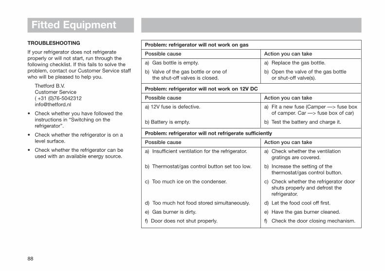
TROUBLESHOOTING
If your refrigerator does not refrigerateproperly or will not start, run through thefollowing checklist. If this fails to solve theproblem, contact our Customer Service staffwho will be pleased to help you.
Thetford B.V. Customer Service( +31 (0)76-5042312 [email protected]
• Check whether you have followed theinstructions in “Switching on therefrigerator”.
• Check whether the refrigerator is on alevel surface.
• Check whether the refrigerator can beused with an available energy source.
Fitted Equipment
88
Problem: refrigerator will not work on gas
Possible cause Action you can take
a) Gas bottle is empty. a) Replace the gas bottle.
b) Valve of the gas bottle or one of b) Open the valve of the gas bottlethe shut-off valves is closed. or shut-off valve(s).
Problem: refrigerator will not work on 12V DC
Possible cause Action you can take
a) 12V fuse is defective. a) Fit a new fuse (Camper —> fuse boxof camper. Car —> fuse box of car)
b) Battery is empty. b) Test the battery and charge it.
Problem: refrigerator will not refrigerate sufficiently
Possible cause Action you can take
a) Insufficient ventilation for the refrigerator. a) Check whether the ventilation gratings are covered.
b) Thermostat/gas control button set too low. b) Increase the setting of the thermostat/gas control button.
c) Too much ice on the condenser. c) Check whether the refrigerator door shuts properly and defrost the refrigerator.
d) Too much hot food stored simultaneously. d) Let the food cool off first.
e) Gas burner is dirty. e) Have the gas burner cleaned.
f) Door does not shut properly. f) Check the door closing mechanism.

Fitted Equipment
89
GUARANTEE, CUSTOMER SERVICE ANDLIABILITY
Guarantee
Thetford B.V offers the end users of Thetfordrefrigerators a three-year guarantee, insteadof the normal guarantee of two years. Thisextra year guarantee applies only if it can bedemonstrated that the refrigerator has beenproperly maintained (as described in thismanual) and serviced by a qualified partyduring the second year following purchase. Inthe case of defects within the guaranteeperiod, Thetford will replace or repair theproduct. In this instance, the costs ofreplacement, labour costs for thereplacement of defective components and/orthe costs of the parts themselves will be paidby Thetford.
1. To make a claim under this guarantee, theuser must take the product to a ServiceCentre recognised by Thetford. The claimwill be assessed here.
2. If components are replaced during repairunder guarantee, these become theproperty of Thetford.
3. This guarantee does not prejudice currentconsumer protection law.
4. This guarantee is only applicable if theproduct is supplied within the EuropeanCommunity.
5. This guarantee is not valid in the case ofproducts that are for, or are used for,commercial purposes.
6. No claim under the guarantee will beaccepted in the following circumstances:
- the product has been improperly usedor the instructions in the manual havenot been followed
- the product has not been installed inaccordance with the instructions
- alterations have been made to theproduct
- the product has been repaired by aService Centre not recognised byThetford
- the serial number or product code hasbeen changed
- the product has been damaged bycircumstances outside the normal useof the product
Liability
Thetford is not liable for loss and/or damagecaused directly or indirectly by use of therefrigerator.
ENVIRONMENT
Refrigerators manufactured by Thetford B.V.are PCB-free. Most of the refrigerator isrecyclable.
If the refrigerator has reached the end of itsservice life, contact your local wasteprocessing company to dispose of therefrigerator in an environment-friendly way.
Energy-saving tips
• Install the refrigerator and switch it onabout 12 hours before you put anything init.
• Do not expose the refrigerator to directsunlight.
• At an ambient temperature ofapproximately 25°C you can let therefrigerator operate at the middle positionof the thermostat (both with gas operationand mains voltage).
• Store foods that have been pre-cooled.
• Open the door only briefly when you takethings out of the refrigerator.
• Defrost the refrigerator regularly.

When cooking with fat or oil, never leaveunattended.
Turn pan handles inwards so they are out ofreach of children and cannot be caughtaccidentally.
Glass lids may shatter when heated, turn offall burners before shutting the lid.
Models without ignition button: For safetyreasons, we recommend the use of a handheld spark ignitor or gas lighter to ignite theburner, rather than a match or taper, whichcould allow burning debris to fall behind theappliance.
When you have finished cooking, checkthat all controls are in the off position.
THE HOB
Caution:• Do not use foil on the hob, as it creates a
fire hazard
• Glass lids may shatter when heated, turn off all burners before shutting the lid
• Note: When positioning the pan support, ensure that the fingers are central to the burners (Fig 1).
Always use the most appropriate size ofburner for the pan you wish to use. Usepans with a flat base of minimum 100mm/4ins diameter, and maximum 200mm/8 insdiameter, which are stable in use. Avoid oldor misshapen pans as these may causeinstability.
following information so the appliance can becorrectly identified:
1. The name of the appliance from the facia, and its colour.
2. The model number and the serial number of the appliance (from the data badge).
BE SAFE - NOT SORRY
Warning: Good ventilation is essential to thecontinuing safe operation of all gasappliances. Do not allow any ventilationopenings to become accidentally ordeliberately blocked.
Keep all flammable materials (such ascurtains, furnishings, towels and clothing)away from the appliance.
Parts of the appliance may be hot during orimmediately after use. Allow sufficient timefor the appliance to cool after switching off.
When opening the appliance door, take careto avoid skin contact with any steam whichmay escape from the cooking.
Do not use aluminium foil to cover the grillpan, or put items wrapped in foil under thegrill as this can create a fire hazard.
Do not use the oven with the door inner glasspanel removed (glass oven doors only).
If the cooker has a storage compartmentbelow the oven, this should only be used tostore oven furniture. Do not store anyflammable materials in this compartment.
Fitted Equipment
90
PLEASE READ THE MANUFACTURERSINSTRUCTIONS BEFORE OPERATING THEAPPLIANCE
WARNING: When you are cooking it isessential to provide additional ventilationsuch as opening windows near the grill,cooker and oven.
WARNING: When using cooking orheating appliances, surfaces and handlesmay become hot. Care should be takenand if necessary hand protection used.
STOVES HOBS, GRILLS ANDOVENSBURNER IGNITION
The hotplate lid must be open for thehotplate, grill or oven burners to ignite.
The ignition should not be operated for morethan 15 seconds. If, after 15 seconds theburner has not lit, stop operating the ignition,open the compartment door and wait at least1 minute before attempting to ignite theburner.
In the event of the burner flames beingaccidentally extinguished, turn off the burnercontrol and do not attempt to re-light theburner for at least 1 minute.
SPARE PARTS
When ordering spare parts, please give the

Fitted Equipment
91
The high speed hotplate ring (if fitted) isidentified by its central red spot - this ringhas a faster response time.
THE GRILL
• Note: The door must be open when the grill is used.
• Caution: When the grill is being used, accessible parts may be hot; young children should be kept away.
• Never cover the grill pan or grid with cooking foil, or allow fat to build up in the grill pan as this creates a fire hazard.
• Keep all flammable material away from theappliance.
To light the grillPush in the control knob and turnanticlockwise to the large flame symbol.Keep the knob depressed, and press theignition button (if fitted), or use a hand heldspark ignitor or gas lighter. The knob mustbe held in for 15-20 seconds beforereleasing.
Detachable grill handle (if supplied)Place the handle (shield uppermost) over theedge of the grill pan at the recess and slidealong to position centrally between the twolocator bumps. To remove the handle, placethe grill pan down, and lift the handle slightlyas you slide it along the recess.
Using the grillPush in the grill pan until it locates centrallyunder the grill burner
There are three different grilling positions asthe trivet can be inverted to give a high orlow position or it may be removed.
1. The high trivet position is suitable for toasting bread.
2. The low trivet position is suitable for grilling all types of meat.
3. With the trivet removed the food is placeddirectly on the base of the grill pan, eg; when cooking dishes such as whole fish.
Always preheat the grill for 3 minutes forbest results.
When you have finished grilling, check thecontrol knob is in the off position
THE OVEN
Caution: When you are cooking, keep children away from the vicinity of the oven.
• Important: A safety device stops the ignition being used when the oven door is closed.
• Do no use foil on the oven shelves as this creates a fire hazard, and can hinder circulation of heat.
• Keep all flammable material away from the appliance.
Important: Any spillage of liquid should becleaned away immediately to reduce the riskof fluid entering the appliance.
Ignition - Push in the control knob and turnanticlockwise to the large flame symbol.Keep the knob depressed, and press theignition button (if fitted), or use a hand heldspark ignitor or gas lighter. The knob mustbe held in for 15-20 seconds beforereleasing.
ELECTRIC HOTPLATES
Before using for the first time, prime thehotplate - switch it on without a pan toharden and burn off the coating. Use amedium-high setting for 3 - 5 minutes. Anon-toxic smoke may occur.
To switch on, turn the hotplate control knobto the required setting.
Stoves Hob

Fitted Equipment
92
To light the oven
1. Open the oven door and turn the control knob anticlockwise to the required gas mark. Push in and hold in the control knob, and either press the ignition button (if fitted) or use a hand held spark ignitor or gas lighter.
2. Once the burner has lit, close the oven door and hold the knob in for 15-20 seconds.
3. If the flame goes out, the flame sensing device cuts off the gas supply to the burner. To light the oven again, wait for 3
minutes then repeat the above procedure.
To turn off - Push in the control knob andturn clockwise.
PreheatingThe oven must be preheated for 10 minuteswhen reheating frozen or chilled food, and werecommend preheating for all yeast mixtures,batters, soufflés and whisked sponges.
Using the ovenThe shelf positions in the oven can bealtered. If you prefer darker cooked results,cook on a higher shelf. For paler results usea lower shelf.
The cake tray and roasting tin that aresupplied with this appliance are the largestwhich can be used for good results and evenbaking. Extra shelves, tins or trays can beordered from your supplier.
Place food items on the tray and position thetray on the centre of the shelf, leaving oneclear shelf position between shelves to allowfor circulation of air.
CLEANING
Caution: Any cleaning agent usedincorrectly may damage the appliance.
Always let the appliance cool beforecleaning.
Some cooking operations generate aconsiderable amount of grease. Thiscombined with spillage can become a hazardif allowed to accumulate on the appliancethrough lack of cleaning. In extreme cases
this may amount to misuse of the applianceand could invalidate your guarantee.
Do not use caustic pastes, abrasive cleaningpowders, coarse wire wool or any hardimplements as they will damage thesurfaces.
All parts of the appliance can be safelycleaned with a cloth wrung out in hot soapywater.
Burner caps and heads
Important: Allow burners to cool beforecleaning.
Caution: Hotplate burners can be damagedby soaking, automatic dishwashers (ordishwater powders/liquids), caustic pastes,hard implements, coarse wire wool andabrasive cleaning pastes.
For the burners to work safely, the slots inthe burner head, where the flames burn,need to be kept clear of deposit. Clean witha nylon brush, rinse and dry thoroughly.
Clean with a mild cream cleaner eg; Jif, oruse a moist soapy Brillo pad.
Note: Fixed burners (if fitted): Some versionsincorporate fixed burners. These burners aresecured to the hob with 2 screws. Fixedburners must be cleaned whilst in position.Make sure that the gap between the burnerand the hotplate does not become blockedwith grease.

Fitted Equipment
93
Glass parts (if fitted)
DOOR PANELS, FACIA PANEL, HOTPLATE LID
Do not use abrasive cleaners or polishes.Use a mild cream cleaner, eg; Jif. Rinsethoroughly and dry with a soft cloth.
The inner door glass panel can be removedfor cleaning; open the door wide, hold thebottom and top edges and slide out. Whenreplacing the glass panel, hold it level andstraight with the grooves in the door trimsbefore sliding back in.
Painted, plastic and gold coloured parts
DOOR FRAME & HANDLES, CONTROLKNOBS
Only use a clean cloth wrung out in hotsoapy water.
Vitreous enamel parts
GRILL PAN, HEATGUARD, OVEN/GRILLCOMPARTMENT(S), HOB SPILLAGE WELL,PAN SUPPORTS
Use a mild cream cleaner. Look for one thathas the Vitreous Enamel Council'srecommendation seal, eg; Jif.
Chrome plated parts (Fig 1)
GRILL GRID, SHELVES, SHELF RUNNERS
Do no use abrasives or polishes. Use amoist soap pad, eg; Brillo. Shelf runners can
be removed for cleaning. Grasp the runnersand slide out of the hanging holes as shownin fig 1.
Stainless steel surfaces (stainless steel models only)
Only use a clean cloth wrung out in hopsoapy water, and dry with a soft cloth. Donot use undiluted bleach or any productscontaining chlorides as they can permanentlydamage the steel.
Some foods are corrosive, eg; vinegar, fruitjuices and salt, and they can mark ordamage stainless steel if they are left on thesurface for any length of time. Wipe anyspillage immediately.
Sharp objects can mark the surface ofstainless steel but will become lessnoticeable with time.
Electric hotplates
Important: Ensure that elements are switched off and cool before cleaning
For normal cleaning use a clean damp cloth.For heavy cleaning, use a clean damp clothor scouring pad with a cream cleaner.
Follow the circular grooved pattern on thehotplate. Rinse off any cleansing agentthoroughly, then switch on to a low-mediumsetting for few minutes to dry. When cleaningtake care to avoid the red dot on the highspeed hotplate (if fitted).
Fig. 1 Chrome Plated Parts

Fitted Equipment
94
THETFORD CASSETTE PORTA POTTIINTRODUCTIONThe Cassette Porta Potti is constructed ofhigh quality plastics for durability and has ahigh gloss finish that is easy to clean andmaintain. The unit consists of two sections, apermanently installed toilet system and aslide out waste holding tank — CASSETTE.
The toilet section includes a seat and cover,flush and valve blade opener knob, toilettissue compartment and holder, waste levelindicator, built-in toilet fluid storagecompartment, a drip tray — a drain tubeassembly and a fresh water tank.
The unique Cassette section is locatedunderneath the toilet and is removed foremptying from outside the caravan throughan access door. A rotating pour-out spout,automatic holding tank vent, air releasevalve, valve blade, carrying handles andhand grips are incorporated into theCassette.
PREPARING FOR USE1. Open access door on the side of the
caravan and swing out fresh water fill funnel.
2. Fill fresh water tank using a hose or jerrycan until water funnel level reaches neck. Tank capacity is 15 litres. Aqua Rinse may be added to improve cleaning of bowl and flushing of unit.
3. Replace cap. Swing water fill funnel inward until it touches side of water tank. Note: 150ml of water will remain in fill bottle when fresh water tank is empty.
4. Next add Aqua Kem to Cassette for controlling odours. Depress retaining clip.
5. Remove cassette by pulling straight out. When Cassette hits stop, tilt downward slightly and remove (stop for safety when Cassette is full).
6. Position tank vertical and swivel pour out spout upward.
7. Remove cap. Remove deodourant from storage compartment. Add 100ml of AquaKem or 120ml of Aqua Kem Bio through pour out spout. Add small amount of water through spout to cover tank bottom. Replace cap and return pour out spout to its original stored position.
Note: As an alternative deodourant can beadded to Cassette through the valve bladeopening. Hotter weather or longer retentiontime may require addition of more Aqua Kem.
CAUTION: Do not add Aqua KemConcentrate or Aqua Kem Bio directly intotoilet bowl while Cassette tank valve blade isclosed. Pressure due to heat and altitudechange can build up in the Cassette tankcausing bowl contents to splash upwardupon opening the valve blade, if opened toofast. Before each use, open and shut theCassette valve blade to vent the tank
1 2
3 4
5 6
7

Fitted Equipment
95
8. Slide the Cassette, pour out spout facing outside into the caravan through access door. Never force insertion or removal of the Cassette tank, damage to system can occur.
9. Make sure the Cassette is secured by the retaining clip. Close and lock access door.
OPERATION
Flushing (Electric Models)10.Before using the toilet we advise to add
some water to the bowl by pressing downthe flush knob. This avoids marking the bowl. Water will stop flowing when knob is released.
11.To flush after use, press the flush knob down while turning in an anti-clockwise direction. The turning motion opens the valve blade, emptying the toilet bowl. Thisprocedure results in the best bowl rinse and most efficient use of water. After flushing, turn the knob in a clockwise direction to close the valve blade. The toilet can also be used with valve blade open, which allows the waste to go directly into the holding tank.
Flushing (Manual Models)10.Before using the toilet, we advise you to
add some water to the bowl by turning the flush knob in clockwise direction. When flush knob is released it will turn automatically back.
11.To flush after use, turn the valve knob in anti-clockwise direction and turn the flush knob. This procedure results in the best bowl rinse and most efficient use of water.
TOILET TISSUE12.Toilet tissue is stored in the specially
designed storage compartment that helpskeep tissue clean and dry (electric modelsonly). Tissue can also be suspended on a tissue holder using the special wall mountbracket, if desired.
13.To replace tissue, remove tissue holder from compartment by pulling up on tissue cover. Hold bottom of tissue holder in onehand and cover in the other, and turn in opposite directions until you hear a click. Pull apart. Place tissue on holder, insert prongs of cover into holder. Hold cover and holder and twist in opposite direction until locked. Aqua Soft toilet tissue is recommended for best results.
Emptying the CassetteThe Cassette capacity is 20 litres and shouldbe emptied when the waste level gaugeindicator goes from green to full red.
The gauge does not begin to move fromgreen to red until the tank is over half full.
8 9
10 ELECTRIC 10 MANUAL
11 ELECTRIC 11 MANUAL
12 ELECTRIC 13 ELECTRIC

Caution: Do not allow Cassette to becomeoverfilled, see Trouble Shooting section foremergency emptying procedure.
The holding tank features a unique slidingcover (1) which guarantees optimal hygiene.The sliding cover moves automatically whenthe holding tank is inserted. When holdingtank is removed, the cover automaticallyassumes its correct position. To clean theholding tank, you may remove the covermanually by sliding it towards the pour-outspout.
To empty Cassette be sure that the valveblade is in the closed position.
14.Open the access door on side of caravan.Depress the retainer clip, pull Cassette until stop, tilt and remove Cassette.
15.Carry the Cassette using the lower carrying handle, pour out spout up, to a normal household type toilet or other authorised disposal point. Set Cassette invertical position on the ground and rotate pour out spout upward.
16.Remove spout cap. Grasp unit by upper carrying handle nearest to pour out spout.Place other hand on upper rear grip so that the air relief valve button can be depressed with thumb while emptying, to ensure smooth outflow of tank contents. When empty, rinse tank and valve blade with water.
Note: Depress air release valve button only when pour out spout is pointed downwards.
17.After preparing for use, slide the Cassetteinto the caravan. Check to make sure thatthe retaining clip secures the tank in a locked position. The pour out spout end of the tank should be visible through the access door opening. Add water to the fresh water tank as outlined in “Preparing for Use” section. Close and lock access door.
CLEANING AND MAINTENANCENo routine maintenance is required on theThetford Cassette Porta Potti. The use ofAqua Rinse helps to clean and protect thetoilet bowl, valve blade and seals duringflushing. Do not use strong householddetergents or cleaners with chlorine, solventsor acid contents, as they will damage valveseals.
Empty Cassette and rinse tank with clearwater. Use a mild soap to clean toilet bowl,seat and cover, as well as exterior of toilet
Fitted Equipment
96
unit and Cassette. Replace tank insidecaravan.
Note: Pour-out spout and vent plug can beremoved. Seals should be greased ifnecessary with acid-free vaseline.
14 15
16 17
18 19 ELECTRIC

Fitted Equipment
97
C-200 CW only C-200 CWE onlyC-200 CWonly
THETFORD CASSETTEC-200 CW (Manual)and C-200 CWE (Electric)FEATURES1. Removable seat and cover.2. Rotatable bowl.3. Valve blade handle: opens and closes
valve blade.4. Flush-handle activates the flush by lifting
and pushing down the handle.4a C-200 CWE. Flush button: activates
flush.4b C-200 CWE. Valve blade buttons: open
and close valve blade electronically.5. Power-supply for the waste-level
indicator: two batteries, type: Penlite 1,5VAA alkaline.
6. Waste-level indicator: indicates when holding tank requires emptying.
7. Rotating pour-out spout: makes emptyingholding tank easy and convenient.
8. Upper carrying handle9. Automatic holding tank vent: vents the
holding tank when the tank is inserted in the toilet. This prevents under- or overpressure in the holding tank.
10. Valve blade opener.11. Sliding cover: closes automatically when
holding tank is taken out. Guarantees optimal hygiene.
12. Valve-blade13. Vent button: vents the holding tank to
avoid splashing while emptying.14. Hand grip15. Access door16. Waterfill door
05
04
0604a 06 16
04b
03
0102
08 07 09 14 12
1311
14
10
15
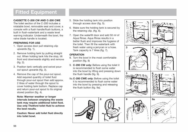
CASSETTE C-200 CW AND C-200 CWE The toilet section of the C-200 includes arotatable bowl, removable seat and cover, aconsole with a flush handle/flush buttons, abuilt in flush-watertank and a waste levelwarning indicator. Underneath the bowl, thevalve blade handle is located.
PREPARING FOR USE1. Open access door pull retaining clip
upwards (fig. 1).
2. Remove holding tank by pulling straight out. When holding tank hits the stop, tilt front end downwards slightly and remove (fig. 2).
3. Position tank vertically and swivel pour-out spout upwards (fig. 3).
4. Remove the cap of the pour-out spout. Add required quantity of toilet fluid through pour-out spout then add approx. 2 litres of water through the spout to cover holding tank bottom. Replace cap and return pour-out spout to its original stored position (fig. 4).
Note: Warmer weather or longer intervals between emptying the waste tank may require additional toilet fluid. Use only Thetford toilet fluid to achievethe best results.
Caution: Never add toilet fluid directly into toilet bowl.
5. Slide the holding tank into position through access door (fig. 5).
6. Make sure the holding tank is secured by the retaining clip. (fig. 6).
7. Open the waterfill door and add 50 ml of Aqua Rinse. Aqua Rinse results in a better flush and improves the hygiene of the toilet. Then fill the watertank with fresh water using a jerrycan or a hose. Tank capacity is 7 litres (fig. 7).
OPERATION8. Turn the bowl in the most comfortable
position (fig. 8)
9. C-200 CW only: Before using the toilet it is recommended to flush some water into the bowl by lifting and pressing downthe flush handle (fig. 9).
9a.C-200 CWE only: Before using the toilet it is recommended to flush some water into the bowl by pressing and releasing the flush button (fig. 9a).
Fitted Equipment
98
87
1 2
3 4
5 6
9 9a

Fitted Equipment
99
10. After use open the blade by turning the blade-handle anti-clockwise (fig. 10).
10a.C-200 CWE only: After use open the blade by pressing the ‘open’ button (fig. 10a).
11. C-200 CW only: To flush, lift the flush handle and press it down (fig. 11). After flushing, close the blade by turning the blade handle clockwise.
11a. C-200 CWE only: To flush press the flush button (fig. 9a). After flushing, closethe blade by pressing the close button on panel (fig. 11a).
The toilet may also be used with the valve blade open, which allows the waste to pass directly into the holding tank.
The waste holding tank is located underneaththe toilet and is removed for emptying fromthe outside of the vehicle through an accessdoor. A rotating pour-out spout, automaticholding tank vent, air release valve, valveblade, carrying handles and hand grip areincorporated in the waste holding tank. Asliding cover guarantees you optimalhygiene.
EMPTYING THE HOLDING TANKThe holding tank capacity is approx. 17 litresand the tank should be emptied when thewaste-level indicator lights up. The waste-level indicator lights up when the holdingtank contains more than 15 litres of waste.
CAUTION: Do not allow the holding tank tobecome overfilled. See trouble shootingsection for emergency emptyingprocedure.
12. Open access door and remove the holding tank. The holding tank can only be removed when the valve blade is closed (fig. 12).
13. Carry the holding tank to a normal household type toilet or other authoriseddisposal point. Place the holding tank in vertical position and rotate pour-out spout upwards (fig. 13).
14. Remove the spout cap. Grasp unit by upper carrying handle nearest to pour-out spout. Place other hand on upper rear hand grip so that vent button can be depressed with the thumb while emptying. This ensures a smooth outflow of the tank contents. (fig. 14).
Note: Only depress the vent button when pour-out spout is pointed downwards.
Rinse the holding tank with clean water. For preparing for use again, see steps 1 to 7.
CLEANING AND MAINTENANCEThe lipseal and the seal of the automatic ventare made of rubber and therefore these partsneed regular maintenance (depending onfrequency of use, once or twice a month).
10 10a
11 11a
12 13
14 15

Lipseal: Remove the sliding cover. Open thevalve-blade by turning the blade-openerknob anti-clockwise. Clean the seal withwater. Dry the seal and grease with siliconespray/oil or vegetable oil.
Seal of automatic vent: Turn the automaticvent 60° anti clockwise and remove gently.Clean the seal with water. Dry the seal andgrease with silicone spray/oil or vegetableoil.
To clean the holding tank, empty the tank,and rinse with clean water. Use a mild soapto clean toilet bowl, seat and cover, as wellas exterior of toilet unit and holding tank.
NOTE: Do not use strong householddetergents or cleaners that contain chlorine,solvents or acid contents.
WINTERING/STORAGEThe Thetford Cassette C-200 CW/CWE iseasily winterised for storage.
Empty remaining fresh water into the bowlby activating the flush handle up and down(C-200 CW) or by pressing the flush button(C-200 CWE).
Once pump has been cleared and water flowhas stopped completely, release into wastetank. Remove waste tank and emptycontents in normal way.
To evacuate any remaining water from thefresh water tank. place a container
underneath the drainplug and removedrainplug.
When procedure has been completedreplace drainplug and waste holding tank(fig. 15). Clean the seals and grease themafter drying (see cleaning and maintenance).
Leave the blade of the holding tank open. Donot replace cap on the pour out spout, toventilate the holding tank. (Also grease theseal of the pour out spout cap.)
COLD WEATHER USEThe toilet can be used in cold weatherconditions provided that the toilet is inheated surroundings. If this is not the case,you can use a nontoxic antifreeze (propyleneglycol) or an antifreeze such as those used incar radiators. Add the antifreeze to the waterin the tank. Add the quantity specified in theinstructions, paying due regard to the safetyinstructions.
HIGH ALTITUDE AND WARM WEATHER USEPressure may build up in the holding tank ifthe tank is not inserted while driving at highaltitudes or in warm weather conditions. Theautomatic holding tank vent will vent thetank when there is over- or under-pressure.High temperatures may require additionalThetford toilet fluid.
Fitted Equipment
100
THETFORD WARRANTY1. The Thetford Cassette is warranted for
one year from the date of purchase, please fill in and return the warranty card.
2. The warranty covers replacement of defective or flawed parts and the inadequate performance of the toilet.
3. In case of a defect apply to an original dealer or Thetford Service Centre with proof of purchase.
4. Defects, which in our judgement occurred from misuse, negligence or accident, are
not covered by the warranty. In addition, the warranty does not apply if the product is installed or handled improperly
or if other than the prescribed toilet fluids have been used or if the product has been altered in any way or has been repaired by unqualified persons, or if the serial number and/or date has been altered or removed.
5. Should the original buyer wish to return tous parts believed to be defective, the parts should be sent prepaid. If we find the parts defective and covered by warranty, they will be repaired and returned. If warranty does not apply or has expired, a nominal charge will be made. Any transport costs are for the account of the owner.
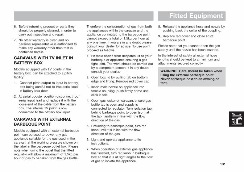
Fitted Equipment
101
8. Release the appliance hose and nozzle bypushing back the collar of the coupling.
9. Replace red cover and close lid of barbeque point.
Please note that you cannot open the gassupply until the nozzle has been inserted.
In the interest of safety all external hoselengths should be kept to a minimum andattachments secured correctly.
WARNING: Care should be taken whenusing the external barbeque point. Never barbeque next to an awning ortent.
6. Before returning product or parts they should be properly cleaned, in order to carry out inspection and repair.
7. No other warranty is given and no personal representative is authorised to make any warranty other than that is contained herein.
CARAVANS WITH TV INLET INBATTERY BOXModels equipped with TV points in thebattery box can be attached to a pitchfacility:
1. Connect pitch output to input in batterybox being careful not to trap aerial leadin battery box door.
2. At aerial booster position disconnect roofaerial input lead and replace it with theloose end of the cable from the batterybox. The internal TV point is nowconnected to the battery box input.
CARAVANS WITH EXTERNALBARBEQUE POINTModels equipped with an external barbequepoint can be used to power any gasappliance suitable for the gas used in thecaravan, at the working pressure shown onthe label in the barbeque outlet box. Pleasenote when using the outlet that the fittedregulator will allow a maximum of 1.5kg perhour of gas to be taken from the gas bottle.
Therefore the consumption of gas from boththe appliances within the caravan and theappliance connected to the barbeque pointcannot exceed a total of 1.5kg per hour atany one time. If you are in any doubt pleaseconsult your dealer for advice. To use pointproceed as follows:
1. Fit male nozzle from despatch kit to yourbarbeque or appliance ensuring a gastight joint. The work should be carried outby a competent person; if in any doubtconsult your dealer.
2. Open box lid by pulling tab on bottomedge and lifting. Remove red cover cap.
3. Insert male nozzle on appliance intofemale coupling, push firmly home untilclick is felt.
4. Open gas locker on caravan, ensure gasbottle tap is open and supply isconnected to regulator. Turn isolation tapbehind barbeque point to open (so thatthe tap handle is in line with the flowdirection of the gas.
5. Returning to barbeque point, turn redknob until it is inline with the flowdirection of the gas.
6. Light and operate appliance to itsinstructions.
7. When operation of external gas appliancehas finished, turn red knob in barbequebox so that it is at right angles to the flowof gas to isolate the appliance.

Fig. C
Fig. A
Fitted Equipment
102
Fig. B
BEDDINGSleeping bags and continental quilts can becompressed into small spaces and can beready to use in minutes.
LOWER SINGLE BEDS ASSEMBLY(Figs. A & B)
1. Unroll bed slat bundle and place between the recess in both seats.
2. Arrange seat cushions as appropriate.
DOUBLE BED ASSEMBLY(Fig. C)
1. Grip front of slatted bed and walk backwards until bed is fully extended.
2. Arrange seat cushions as appropriate.

Fitted Equipment
103
PULLMAN BUNKS
1. Release catches, one at a time.
2. Release press studs on the bed board.
3. Grasp the bunk as shown and pull carefully in direction of arrows.
4. The bunk is designed to automatically move into the correct position.
5. Where a bed board is fitted, unfold and make sure it is secured by press studs when lifted into position. (The bed board is required to protect both the occupant and the window from damage during use of the bunk.)
6. Locate safety boards.
7. Arrange seat cushions as appropriate.
BUNKS ARE DESIGNED TO CARRY ACHILD TO A MAXIMUM OF 70KG (11 STONE)
WARNING: Always ensure safety boards are located before entering the bunk.
WARNING: Care should be taken against the risk of falling out, whenupper bunks are used by children,especially under 3 years of age.

Fitted Equipment
104
KOMFORTROLLO BLINDS (SEITZ)
Blinds and FlyscreensFlyscreen and blinds operate in the samemanner. The flyscreen can only be ‘fully up’or ‘fully’ down, but the blind also has anintermediate position.
To operate, pull down by holding thefingergrip(s), gently ease towards the windowto locate the catches. To retract, pull downeasing away from the window to release thecatches and guide to the required position.
• ONLY OPERATE BY HOLDING THE FINGERGRIP(S) - pulling on one side will cause uneven running and snagging.
• DO NOT ALLOW THE BLIND OR FLYSCREEN TO RE-COIL WITHOUT CONTROL.
• It is not recommended that blinds and/or flyscreens are left in the down position for long periods, or when travelling, as this can result in fatigue of the spring.
• Clean the cassette, side track and fabrics with mild detergent and water.
• Lubrication of mechanism or spring is not required or recommended. However, if components should require cleaning, use only WD40 or similar with fluff-free cloth. Other lubricants may result in damage to fabrics and plastics.
Tension AdjustmentRemove plastic cover (if fitted) to locatetension lugs. The tension lugs have a slotand are located in the cassette on a‘bayonet’ principle. Insert screwdriver intoslot (ensure a good fit), turn lug clockwise toallow the spring tension to push the lugs justfree of the cassette. Keep fingers away fromscrewdriver tip to avoid accidental injury.Spring can now have more or less tensionapplied as required.
If in doubt of tension to be applied, releaseall tension and re-start. In which case, withblind fully wound on the roller, apply 12revolutions of lug (factory setting).
Refitting is a reversal of removal procedure.
For more detailed information, seemanufacturer’s instructions.
Cassette Blind and FlyscreenAlways hold the end rod in the middle. Whenclosing blinds, slide the end rod of theflyscreen blind on to the end rod of the sunblind and engage. To open the blind push theend rods towards the darkening blind to theedge and disengage the end rods. Nowmove the end rod of the flyscreen back byhand - do not let it recoil.
DOORSCREEN
When drawing or releasing the doorscreen,care should be taken not to let it spring backfreely, this may result in damage to thescreen or its fittings.

Fitted Equipment
105
Always pull the doorscreen close to thecentre. It is not advisable to pull close to thetop or bottom as this will cause snaggingand uneven running.
CautionWhen opening or releasing thedoorscreen, care must be taken to avoidtrapping fingers.
Do not allow the doorscreen to slamopen.
SEITZ ENTRANCE DOOR
To open from the outside, pull the openinglever in the door handle.
To open from the inside, pull the openinglever in the recessed handle.
To lock the door from the outside turn thekey to the left, to unlock turn the key to theright.
To lock the door from the inside, depress thelocking button. To unlock pull the handle.
The window is opened by depressing thebutton on the catches and turning through90°, open the pane fully until it locates. Toclose pull the pane back and close thecatches.
The door flynet and blind operateindependently by sliding together andengaging.
ROOF LIGHTSWhen opening the roof lights, care must betaken to release the locking mechanism asthe unit is raised.
Roof lights must be fully closed whentowing.
Roof lights provide 12,500mm2 of fixedventilation each.
WINDOWSTo open press the knobs in the middle of thecatches and turn through 90°. Swivel thepane open as required.
To close the window, open the window as faras possible and slowly close again, turn thecatches through 90° to close.
All opening windows have two catchpositions. The first position is for ventilationthe second seals the window from ventilationand rain.
HEKI-2 ROOF LIGHT (SEITZ)The lift/tilt roof light can be set in 3 positionsby means of pneumatic springs.
Position 1 lifts the pane 12mm withoutallowing rain to enter the caravan.
Position 2 sets the pane to a 150mmopening and locks with a bar.
Position 3 opens the pane through 55°.
A fully adjustable flyscreen and black-outscreen are built into the inner frame. Theflyscreen can be drawn independently andthe black-out screen is variable for partial orfull black-out.
Forced ventilation functions via a brush linedduct instead of a ventilated pane.
A cover hood can be fitted for winterprotection.
Heki-2 roof lights provide 13,200mm2 of fixedventilation
MINI HEKI ROOFLIGHTTo open depress button and push barupwards. The rooflight has two openventilation positions and a fully openposition.
The blind and flynet operate independentlyof each other and are engaged byconnecting to each other and sliding.

Fitted Equipment
106
THE OMNIVENT (12V) ROOFLIGHT
The Omnivent is a double glazed rooflightconstructed from a synthetic ultra-violetscreened material. Its side operatingmechanism allows a completely free centralopening with built-in fixed ventilation whenclosed.
Red Switch = Mode of OperationInduction (IN)Expel (OUT)
Black Switch = Speed Control1, 2 and 3
Omnivents give no fixed ventilation when seton induction.
INOFFOUT
THE BLIZZARD 1500 AIR CONDITIONER
To set the required temperature adjust theRED/BLUE selector control knob against theindicator mark on the outer bezel. Airflowdirection can be achieved fore and aft byadjustment of the air outlet louvres.
AttentionNever obstruct the air inlets and outlets
The air conditioning compressor runs duringthe refrigerating phase, if switched on and offat once it may get damaged. Therefore, it isvery important to wait at least 3 minutesbefore attempting to switch it on again.
Electrolux
MainSwitch
Position air conditioner ONPosition air conditioner OFF
Position fresh airPosition warm air
ON-OFF
Warm/ColdDual Switch
Starting and function selection
Warm-Cold
FanSwitch
Position high speedPosition low speed
Air Speed
Thermostat By rotating the knob clockwise, temperatureincreases (max 40°C)By rotating the knob anti-clockwise,temperature reduces (min 18°C)
Air Temperature(18°C-40°C)

Fitted Equipment
107
WARNING: Never introduce your hands or other object within the air inlet openings.
MaintenanceTo ensure trouble free running it isrecommended that the unit be cleaned onceor twice a year.
Never attempt the following until the power isdisconnected and the unit is cool
Remove dust and dirt with a damp cloth (donot use petrol or solvents).
Check that water trap holes are not clogged.
Periodically open cover and clean filters bywashing with a mild detergent solution andallow to dry before refitting.
The Blizzard air conditioning unit provides nofixed ventilation.
ASH FRAMED DOORSIn order to provide customers with the latestdesigns of door furniture it is possible, due tothe use of natural wood, that warping mayoccur. This should not detract from thecorrect functioning of items fitted in thecaravan.
Fig. A
SHOWERWhen using the shower, always ensure thatthe shower curtain is fully drawn thusavoiding water spray on unprotected areas.
TABLESSlide top of drawers out and fold back toform convenient table. (Fig. A)
The pedestal table can be swung round foreasy access to the seating and then re-positioned afterwards. (Fig. B)
Tables stored in the table storagecompartment must be securely clipped intoplace whilst in transit.
CAUTIONWhen erecting the free standing table, becareful to avoid trapping fingers.
Fig. B

Fitted Equipment
108
NOT TO SCALE
FIXING OF AWNINGSIn order to avoid puncturing the outer skin ofthe caravan wall, it is recommended thatawning poles are fixed to your caravan usingload spreading eyelet pads or rubber suckerpads.
Attaching awning brackets and associatedfixings to your caravan by using mechanicalmethods which pierce the outer skin of thecaravan wall can allow water ingress whichwill invalidate the product warranty.
Important:Care must be taken when using an awningas poles and suckers can cause damage toexterior side panels.
Awnings should be taken down in strongwinds to protect the side panels fromcosmetic damage and dents from the awningpoles.
Note:Awnings should be kept ventilated whendischarging products of combustion exhaustinto them.
Awning SizesDue to the various awning types and sizesthe awning sizes provided in the Service andWarranty Handbook are for guidance only.
Specific awning sizes must be confirmedwith the dealer or awning manufacturer priorto purchase.
POSITION OF AWNING BLOCK
20mmAvailable block on sweep forawning bracket
Inner line ofawning channel
DETAIL OFSWEEP
Block - 5” x 17⁄8” (125 x 45mm)
Block
Wheel Arch

MAINTENANCE
Modifications ........................................................................ 110Caravan Exterior .................................................................. 110Caravan Interior .................................................................... 110Winterisation/Storage .......................................................... 111Alko Running Gear ............................................................... 113
Care and Maintenance ....................................................... 113Axle Types ........................................................................... 115Spare Parts ........................................................................ 116Braking System Adjustments.............................................. 117AK160, AK300 and AK350 Operation................................. 120AKS 2004 Operation ............................................................122Trouble Shooting ................................................................. 132
Accessories .......................................................................... 134Corner Steadies ................................................................. 134Shock Absorbers ................................................................ 134Stabilisers............................................................................ 134Road Wheels ....................................................................... 134Jockey Wheel ..................................................................... 135Spare Wheel Carriers .......................................................... 135

Maintenance
MODIFICATIONS - DIY WORKOwners need to be aware that carrying outDIY modifications to your caravan may incertain instances, invalidate the warrantycover and could also affect the safety andstructure of the caravan.
Before carrying out any DIY work within thewarranty period (3/5) years please check withyour nearest Swift Group dealer or contactSupercare customer services on 01482875740 for advice.
CARAVAN EXTERIORAluminium PanelsThe stove enamelled paintwork is verydurable and easy to clean owing to the highgloss properties.
Plastic Panels (GRP/ABS)These are used for front and rear panels and,in some cases, for roof and side panels.
CleaningFor both aluminium panels and plastic panels.
1. Wash the caravan regularly with mild detergent. Rinse with cold water and leather off.
2. For better protection a similar coloured good quality car wax may be applied.
When cleaning Sikaflex sealed areas, useDomestos/water.
WARNING: Under no circumstances use any abrasive cleaning agents or solventson the exterior panels.
Care should be taken as the silicon in some polishes can attack the rubber used on the exterior for seals and gaskets.
MouldingsAll mouldings are of anodised aluminium andwill retain their lustre for a long period if noabrasive materials are used to clean them.
Acrylic WindowsWash windows carefully, as you would withthe paintwork of your car, do not scrubwindows prior to removing surface dirt andfilm with a hose pipe - trapped dirt couldcause scratching.
Wash with a solution of warm soapy water,windows can then be dried off with a leather.
Small scratches can be removed, consultyour dealer.
Catches and stays do not require any specialattention or lubrication.
CondensationAs your caravan is double glazed you mayoccasionally get condensation inside thedouble glazing. This is particularly so insevere weather change (usually spring andautumn) and is easily cured in dry weather.
i) Remove the plastic plugs from interior top of each window.
ii) Leave unplugged for approximately 1-4 hours until condensation has cleared.
WARNING: Do not wash your caravan with a high pressure washer as these can permanently damage the seals of your caravan.
CARAVAN INTERIORFollow these guidelines to ensure yourinvestment is receiving the very bestattention.
Side Walls, Roof LiningA simple wipe over with a damp cloth and avery mild detergent is all that is needed.
Soft FurnishingsShould be vacuumed occasionally to removegrit and sand and help to keep its smartappearance and ensure long life. Theupholstery can be cleaned with a mild,reputable upholstery cleaner. It isrecommended that the curtains and pelmetsare specialist cleaned only. The foam used incushions is manufactured to meet fireregulations. It requires time to return to itsnormal position after prolonged use.
Work SurfacesYou should not stand very hot items on anyof the work surfaces, especially models withpolycarbonate moulded sinks and drainers.
110

Maintenance
111
Cupboard CatchesIt is advisable to lightly oil all cupboardcatches, sliding bolts and hinges from timeto time.
Bathroom, Shower Room and KitchenEquipmentAll the Thermoplastic parts in these areashave easy clean surfaces. To ensure long lifeand prevent damage you must not use anycleaning materials at all and ensure watertemperatures do not exceed 70°C, (puttingcold water in first is suggested). After everyuse it is essential that you rinse with cleanwater only and wipe with a soft damp cloth.Failure to follow these simple instructionsmay result in premature failure or crackingwhich will not be covered by any guarantees(including extended warranties).
FurnitureA simple wipe over with a damp cloth shouldbe all that is required. Polishing with aproprietary brand of wax polish enhancesand maintains furniture in showroomcondition.
It must be remembered that because theframes of the doors are made of ash, whichis a natural product, they can be affected bytemperature and humidity and may bowunder certain conditions. As conditionschange they should revert to their originalpositions.
Kitchen Drainer and Cutting BoardYou should not stand hot items on to theremoveable plastic kitchen drainer. To washuse only warm soapy water, do not usechemicals and bleach.
The round wooden kitchen cutting board canbe lightly brushed with vegetable oil toenhance it.
WINTERISATION/STORAGEThis is probably an opportune moment toarrange for the caravan to have its annualservice at your appointed dealer.
The following applies wherever your caravanis stored particularly during the wintermonths.
Do not park near trees or larch type fences,due to possible wind damage.
Keep any grass around the floor of thecaravan short, to maintain air flow and stopany possible damp getting into the caravan.
It is advised that the caravan is ventilatedregularly throughout the winterisation/storage period, opening windows, doorsand rooflights when possible.
GeneralAll moving parts should be checked for freeoperation.
Clean all cooking appliances and refrigerator.
Lubrication should be carried out at thepoints illustrated in the general notes onchassis maintenance (page 98).
Charge up the on-board battery every 2months.
Check alarm battery condition every 2months and charge if necessary.
Leave the refrigerator door open.
Leave furniture doors and lockers open toallow air to circulate fully.
CondensationCondensation will occur when humiditylevels rise. Correct heating and ventilationwill help reduce this. When cooking or in wetinclement weather increased ventilationthrough windows and rooflight will berequired.
Soft FurnishingsClean and dust the upholstery and ifpossible remove before placing the caravaninto winter storage. Alternatively, stand thecushions on their edges to allow circulationof air. This will reduce the possibility ofdampness from condensation.
Keep curtains or blinds closed, to minimisefading of furniture.
If the blinds and/or flyscreens remain downfor a prolonged period of time, re-tensioningof the springs will be necessary before re-use.

Fig. 1
MaintenanceWheels and TyresDo not store in one position with partiallydeflated tyres. The tyre walls will suffer and dopresent a real danger of blow outs, especiallywhen travelling at faster speeds than areallowed in the UK.
The wheels should be turned every couple ofweeks or even better, the wheels removed andthe caravan placed on “winter wheels” or axlestands.
If you are removing the wheels, follow thejacking procedure for changing a wheel.
Check your tyres regularly for signs of ageand deterioration, particularly wear, crackingand blistering. If in doubt consult a reputabletyre fitter.
Water System
Ensure water pump is turned off.
Lift kitchen sink unit lid and clip in openposition.
All single lever mixer taps, including theshower control, should have the lever movedto the central position and lifted to the openposition for hot and cold.
All conventional taps should be opened.
Remove shower head. Let the shower hosedrain into the shower tray and then return toholder.
Drain water tanks if fitted:Internal tanks- open inline valve adjacent to
the tank. Valve is open when handle is inlinewith valve.External underslung tanks - remove drainpipe from retaining clip and open tap. Allowwater to drain. Clip pipe back in position.
Open system drains. Remove red drain plugfrom under the floor of the vehicle (Fig.1) andplace in drawer.
Drain water heater. Open yellow handle oninline valve adjacent to heater. Valve is openwhen handle is vertical.
Before recomissioning the system reverse allabove actions. (See Taps in Services section)
The Thetford Cassette porta potti is easilywinterised for storage. Empty the fresh watertank using the drain tube/fresh water tanklevel indicator (level indicator on electronicmodels only). Pull the lever indicator/draintube down from top plug position andoutward through door opening to drain water
from the tank.
Empty the water fill funnel by pulling thebottle away from tank. Remove the smallwater cap on the filler bottom, allowing waterto drain from the water funnel. (Not C-200toilet).
Do not tighten caps, this helps in keepingunit dry.
The pour out spout and vent plug can beremoved. Seals should be greased ifnecessary with acid-free vaseline.
Recomissioning the Water SystemFill the fresh water tank on the ThetfordCassette porta potti using a hose or jerrycanuntil the water in the funnel reaches the neck.Tank capacity is 15 litres. Aqua Rinse may beadded to improve cleaning of bowl andflushing of unit.
Replace cap. Swing back the water fill funneluntil it touches the water tank.
Add Aqua Kem (100 ml) into the Cassette (or120 ml if using Aqua Kem Bio) through thepour out spout. Add small amount of waterthrough the pour out spout and replace thecap.
It is advisable after storage to flush the watersystem initially with a sterilising agent (suchas Milton), and then with water repeating untilthe system is well flushed through.
Connect the pump.
Fill the system with water until water flows
112
Push up collar (A) torelease and pull plug(B) down to remove.
B
A

Maintenance
ALKO RUNNING GEARCARE & MAINTENANCE INSTRUCTIONSFOR YOUR AL-KO CHASSIS ANDCOMPONENTS
General InformationThe AL-KO lightweight chassis has beenperfected by many years of research anddevelopment, supported by an exhaustivetest programme.
Manufactured from high quality steel, thechassis has extra deep sections to providestrength at points of maximum stress. Largeelongated holes are punched in thelongitudinal chassis members, to reduceweight to a minimum. Each hole incorporatesa return flange to maintain the requiredstrength and provide rigidity in the extradeep sections.
The chassis frame is of a bolted constructionwhich allows replacement of individual partsshould the need arise.
The chassis is Hot Dipped Galvanised. Thisis regarded as one of the best forms ofcorrosion protection. It does howeverrequire minimal maintenance in certaincircumstances and should, if properlymaintained, last the lifetime of the vehicle.
When new, the chassis is of a bright andshiny appearance. As the galvanising curesduring the initial 2/3 month period, this will
gradually change to a medium/dark greycolour. This grey finish is the ideal, giving thecorrect protective coating. During this curingperiod the surface should be protected toavoid possible wet storage stain, in theform of a soft, light coloured, porous,oxidation layer. If the chassis members are incontact with any salt deposits from roadsthis should immediately be washed off with ahigh pressure washer. Salt attracts moistureallowing the surfaces to remain wet, thisprevents curing and also allows formation ofwet storage stain.
It is recommended that the chassis/components are washed off, using apressure washer on an annual basis(especially after winter usage), to avoidundesirable build up of salt and dirt deposits.
The galvanised chassis should not bepainted or subjected to any other protectivetreatment.
Should the galvanising become superficiallydamaged exposing the steel core, thisshould be cleaned and treated with a ColdGalvanising Spray obtainable from vehicleaccessory outlets.
Damage to chassis members through impactetc, MUST NOT be straightened or welded.Damaged chassis members MUST bereplaced.
113
freely from the hot taps. About 2 gallons ofwater will be required. Close the hot taps.
AppliancesBefore starting caravanning after storagecheck all gas appliances and electricalpoints.
Note: Preferably not less than once a year,the electrical installation should be inspectedand tested by a qualified electrician.
After storage it is advisable to air the caravanand clean throughout, especially cookingappliances and the refrigerator.
Replace the bedding and wheels if they wereremoved for storage.
ImportantAlways follow the manufacturersrecommended procedures after use of fittedequipment in the caravan and before storingfor any length of time.

Maintenance
114
Drilling or Welding of Parts or Accessories
The chassis is designed and built to precisetolerances and must not be drilled orwelded (except in accordance with certainAL-KO Accessory Operating Instructions).Failure to comply will invalidate allwarranties.
Independent Suspension
The AL-KO rubber suspension is designedand developed to suit all types of roadconditions and is maintenance free. Threerubber elements are contained within ahexagonal axle tube. These providesuspension and have inherent dampingcharacteristics. (Only the hubs and wheelbrakes require attention - see axle section).
Loadings on Coupling Heads, OverrunAssemblies and Axles
The permitted ‘nose’ weights of the couplinghead/stabiliser, overrun assembly anddrawbars, must never exceed the lowestvalue stamped on the assemblies.
The maximum axle loading is that stampedon the oval (Fig. 1) plate located in thecentre of the axle, facing rearwards. Thethird line down marked “Capacity” is themaximum permitted axle loading andmust not be exceeded.
Where the Caravan Manufacturer states amaximum loading weight, then this is themaximum permitted load. This figure mustnot exceed the maximum axle load.
Enter your Axle details for future reference:
Loading
Loads to be carried in the caravan should beplaced directly over, or as close as possibleto the axles, otherwise the handling will beimpaired.
Maximum gross weight, as advised by thecaravan manufacturer, must not beexceeded without approval from AL-KO.
Maximum loading is defined as thedifference between ex-works weight and thepermitted total weight.
Load Too Far Forward (Fig 2)Steering and braking ability reduced.Increased loading on the rear axle andchassis of the tow vehicle.
Load Too Far Back (Fig. 3)High skid risk together with poor brakingeffect.
Load Over Axle (Fig 4)Optimum road holding together withmaximum braking effect. Exceptionally heavyloads should packed directly over the axle.
Attention should be paid to the legalregulations regarding the permittedpressure exerted by the towbar on thetowed unit.
Fig. 1
Fig. 2
Fig. 3

Maintenance
115
AXLE TYPES
Safety Precautions
No welding is permitted on AL-KO Axles
It is important that the wheel and hub/ brakedrum are compatible. This mean that thePCD, wheelbolts and inset must all becompatible with both the hub/brake drumand the wheel rim.
Particular attention must be paid to therecommended torque figures for thewheelbolts (see pg 16).
The axle type details shown on axle typeplates must not be obscured or madeillegible by application of any additionalsurface finish.
Operating Instructions
Service Brake
When the towing vehicle is braking ortravelling down hill, the overrun device shaftis pushed in (dependent on the magnitude ofthe thrust on the shaft) and presses on theoverrun lever. This acts on the bowdencables and expander mechanism, which in
turn expands the brake shoes applying thewheel brakes.
Reversing
When the towing vehicle is reversing, theoverrun device shaft is pushing in, applyingthe brakes via the overrun lever, brake rodsystem, bowden cables and the expandermechanism.
The backwards rotation of the brake drumcauses the secondary brake shoe tocollapse cancelling out the braking effect,allowing the trailer to move backwards. Atthe same time the transmission lever swingsback and compensates for the entire travel.
When reversing up a slope or on a loosesurface the brakes may apply themselves,Correct maintenance and set up of thebrakes will help prevent this. Incorrectadjustment of the wheel brakes or Linkageswill result in making reversing difficult.
Hand Brake
With the gas strut version, pull thehandbrake lever until upright. With the springcylinder version, pull the handbrake leverright up to the last tooth. The caravan is thenbraked.
IMPORTANT NOTE
Please note that with the handbrake fullyapplied, the caravan/trailer is able to movebackwards by 25 cms until the springcylinder/gas spring takes effect.
Maintenance and Cleaning
Maintenance of Euro-Plus/Euro-Compactand Euro-Delta.
The above semi-trailing axles come fittedwith maintenance free wheel bearings(greased and sealed for life) and noadjustment is necessary.
NOTE: The hub bearing is not protectedagainst water ingress. Check wheel brakelinings for wear every 10,000 kilometers orevery 12 months via the inspection hole (Fig. 5/Item 1). Adjust if necessary. Wherecontinuous travel in hilly regions or highmileage is experienced, earlier inspectionand adjustment may be necessary.
NOTE: The flanged hub-nut, located underthe dust cap, used to keep the brake drumin situ, is a ONE-SHOT NUT (ie. must onlybe used once). If removed it must be
Fig. 4
Fig. 5

Maintenance
116
replaced with a NEW flanged nut - torquedto 290 ± 10 Nm (214+/1 7.5 lbs/ft). A smallamount of special mineral grease, availablefrom AL-KO must be applied to stub axlethread prior to fitting the new flanged nut.After fitting excess grease must be removedwith white sprit.
The rear hexagon cap head bolt locatedunder the black plastic cap MUST NOT BEDISTURBED under any circumstance.Interference with this nut will result inimmediate tyre wear and damage to thebraking system and WILL INVALIDATE ALLWARRANTIES. Should the rear nutaccidentally be disturbed then the completeaxle must be returned to AL-KO for resettingof the toe-in and camber.
No attempt should be made to remove thebearing. In the event of damage to thebearing or drum, only the drum completewith bearing and circlip will be available as aspare. No grease is used in the hub otherthan the mineral grease on the stub axle. Nogrease should be placed in the DUST cap.This is not a grease cap as used in allprevious hubs
“Standard Axle” Maintenance (taper rollerbearings)
After 1500 km or 6 months
Have the axial play of the hub bearingchecked and adjusted if necessary.
After 10,000 km or 12 months
Check quantity and quality of grease, renewif necessary.
Check the wear of the wheel brake liningsevery 10,000 Km or every 12 monthsthrough inspection hole (Fig. 5) and adjust ifnecessary. Where continuous travel in hillyregions or high mileage is experienced,earlier inspection and adjustment may benecessary.
SPARE PARTS
Spare parts are safety critical parts! For thisreason when fitting spare parts in ourproducts we recommend the use of originalAL-KO parts or those parts that we haveexplicitly approved. The reliability, safety andsuitability of parts designed especially forour products, has been determined using aspecial test procedure. In spite of constantlymonitoring the market we are unable toassess or vouch for other products.
If repair work or servicing is required, AL-KOhave a large network of AL-KO servicestations throughout Europe.
To establish the correct spare parts requiredfor your axle you should always quote theaxle type (axle identification plate Fig. 1) andSpare Part Identification no. (ETI No.), whichwill be stamped onto the wheel brake or onthe identification plate (Fig. 6). Pleaseestablish these numbers before contactingAL-KO or a Service Agent.
The AL-KO rubber suspension axle has beendesigned and developed to suit all types ofroad conditions and is maintenance free.
Three rubber elements are contained withinan hexagonal axle tube. These providesuspension and have inherent dampingcharacteristics.
Figs. 7, 8 & 9 show the deformation of therubber elements at the extremes ofsuspension movement.
The axle is designed to ride with thesuspension drop arm at, or slightly below,the horizontal position.
For Trouble Shooting & Fault Finding pleasesee Table 1 on page 132.
Fig. 6

Maintenance
117
AL-KO BRAKING SYSTEM ADJUSTMENT
1. Ensure the towing shaft with couplinghead is pulled FULLY FORWARD. (Fig.10).
2. Release the handbrake to the FULLY OFFposition. If the handbrake will not godown the whole way because of thefairing or any other obstruction; then thefairing must be cut away and/or theobstruction removed to achieve thisdesired position. It will not be possible toset up the braking system properly whenthe handbrake is not in the FULLY OFFposition. (Fig. 10).
3. Jack up one side of the caravan, usingthe AL-KO Side Lift Jack System. (seeJack Operating Instructions).
4. Remove the inner plastic bung from thebackplate to expose the “starwheel”adjuster access. (Figs. 10 & 11).
5. ALWAYS rotating the road wheel in theforward direction - NEVER backwards;adjust the starwheel with a suitablescrewdriver, in the direction of the arrowembossed on the backplate until there isresistance in the wheel rotation. (Fig. 11).
6. Slacken off the starwheel adjuster untilthe road wheel turns freely in theFORWARD direction. (Fig. 11).
7. Check the adjustment at the end of thebrake cable where it is secured to the
abutment (bracket), welded to the centreof the axle. When the inner cable is pulledout it should extend between 5 and 8mm. (Fig.12). (On tandem axles a doubleabutment (bracket) is fitted to the frontaxle ONLY).
8. Repeat for other wheel or wheels.
9. On tandem axles the brake cables fromthe rear axle should pass over this axleand cross over each other, before beingconnected to the abutment (bracket) onthe front axle.
10. Ensure the balance bar (compensator) isbeing pulled evenly (Figs.10 & 12).Excessive movement to this bar (doubleon tandem axles) would indicate possibleincorrect adjustment (if appropriate,repeat step No. 7 - Fig. 12).
11. Check the brake rod support bracket,(fixed to the floor) IS supporting thebrake rod evenly. The brake rod MUSTALWAYS run straight, NEVER bent orcurved under any fittings. On tandemaxles, using the double balance bar, abrake rod support tube (Part No. 228827)MUST ALWAYS be fitted on the end ofthe brake rod, passing through thecentre aperture on the abutment.
12. Remove the slack in the brake rod byadjusting the long ball nut, rear of thebalance bar, ensuring the overrun levermakes contact with the end of the
Fig. 7 Rebound or Free Position
Fig. 8 Normal or Laden Position
Fig. 9 Maximum Bump
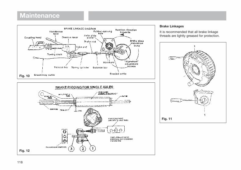
Maintenance
118
Fig. 10
Fig. 11
Fig. 12
Brake Linkages
It is recommended that all brake linkagethreads are lightly greased for protection.
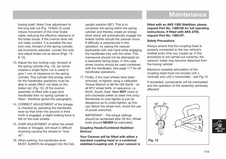
Maintenance
119
towing shaft. Note! Over adjustment tothe long ball nut (Fig. 12/Item 2) couldinduce movement of the inner brakecable, reducing the effective clearance ofthe brake shoes. If the overrun lever willnot make contact, it is possible the twolock nuts, forward of the spring cylinder,are incorrectly adjusted. Loosen the nutsand adjust brake rod as above (Figs. 10& 12).
13. Adjust the two locking nuts, forward ofthe spring cylinder (Fig. 10), (on somechassis a single Nyloc nut is used) togive 1 mm of clearance on the springcylinder. This cylinder (the energy storefor the handbrake operation) must beable to rotate ONLY, not slide on thebrake rod. (Fig. 12). (If the overrunassembly is fitted with a gas struthandbrake then no spring cylinder isfitted - therefore ignore this paragraph).
14. CORRECT ADJUSTMENT of the linkageis checked by operating the handbrakelever so that when the second or thirdtooth is engaged, a slight braking force isfelt on the road wheels.
15. OVER ADJUSTMENT of either the wheelbrakes or linkages, will result in difficultreversing causing the wheels to “lock-up”.
16. When parking, the handbrake leverMUST ALWAYS be engaged into the fully
upright position (90°). This is tocompress the spring within the springcylinder and thereby create an energystore which will automatically engage thebrakes further should the caravan move.If difficulty is experienced in thisoperation, try easing the caravanbackwards with one hand while engagingthe handbrake fully with the other. Thismanoeuvre should not be attempted ona rearwards facing slope. In this casewheel chocks should be used combinedwith the handbrake. See page 117 for allhandbrake operations.
17. Finally, if the road wheels have beenremoved, re-tighten using a calibratedTorque Wrench to 88 Nm (65 lbs/ft) - onall M12 wheel bolts -in sequence, i.e.North, South, East, West NOT clock oranti-clockwise (refers to steel rims only).Remember to over-tighten is just asdangerous as to under-tighten, as thiscan distort the wheel rims. Avoid the useof power wrenches.
IMPORTANT - The torque settingsshould be rechecked after 50 Km. Wheelbolts should NEVER be lubricated.
Coupling Heads/Combined StabiliserDevices
Your Caravan will be fitted with either astandard coupling head or a combinedstabiliser/coupling unit. If your caravan is
fitted with an AKS 1300 Stabiliser, pleaserequest Part No. 1385106 for full operatinginstructions. If fitted with AKS 2700,request Part No. 1385107.
Safety Precautions
Always ensure that the coupling head isproperly connected to the tow vehicle’stowball every time you couple up. If thisprocedure is not carried out correctly, thecaravan/ trailer may become detached fromthe towing vehicle!
Maximum possible articulation of thecoupling head must not exceed ±25 overtically and ±20 o horizontally - see Fig 13.
If exceeded, components will be overloadedand the operation of the assembly adverselyaffected!
Fig. 13

MaintenanceOperation
For Coupling types AK160, AK300 &AK350.
Coupling Up
Open coupling handle. To do this pull thecoupling handle up (Fig. 14) in the directionof the arrow.
The coupling mechanism has a fixed openposition, ie. as long as the coupling head isnot placed on the ball the coupling willremain open.
Put the open coupling onto the towball. Thecoupling handle automatically and audiblyclicks into position. In the interests of safety,press the handle down by hand (Fig. 14).
The coupling head is correctly connectedwhen the green cylinder part of the safetyindicator is visible (when viewed from theside - Fig. 14/Item 2).
The coupling mechanism is correctlyengaged when the coupling handle can nolonger be pressed down any further (byhand).
Caution
If the coupling head is not correctly hitchedonto the towball, then the caravan/trailer canbecome disconnected from the towingvehicle.
Uncoupling
Open the coupling handle and lift thecoupling head from the towball. When thereare higher nose loads, coupling anduncoupling can be made easier by using thejockey wheel.
Wear Indicator
A wear indicator on the coupling head (Fig.15) shows whether the wear limit of thetowing vehicle’s towball or the trailercoupling has been reached or not.
For this purpose, hitch up the trailer to thetowball and drive the unit for approx. 500 m.This will set the coupling head adjustment.Following this, check the wear indicator asfollows.
If the green indicator is visible on thecoupling (with the coupling engaged Fig. 15),the coupling head is in good condition or thewear on the towball is within permissiblelimits.
When the green indicator on the couplinghandle is completely covered over and onlythe red portion is visible (Fig. 15), this couldbe caused by the following:
- The towball has reached the lowest wearlimit of 49.61 mm dia.
- Both coupling head and towball areshowing signs of wear.
120
Fig. 14
Fig. 15

Maintenance
121
Fig. 16
- Towball is in good condition with 50mmdia, but the coupling head is showing anexcessive level of wear.
Caution
Under these circumstances, the couplinghead can become detached from the towballand the caravan/ trailer can breakaway fromthe tow vehicle. The coupling head andtowball must therefore be checkedIMMEDIATELY before future use. Any faultyparts must be changed IMMEDIATELY.
All maintenance work should be carried outby AL-KO Approved Workshops.
Operation
For coupling types AK7, AK 10/2 orAK252. (This type of coupling is normallyfitted to trailers or older model caravans).
Coupling Up
Push the safety lever (Fig. 16/Item 1) up withthe index finger and lift the handle up andforwards. Put the opened coupling onto thetowball with the handle pulled up and inaddition press down by hand. The couplingwill close by applying a light pressure. Pressthe handle down by hand until the catchsnaps out (Fig. 16).
The coupling head is correctly engagedwhen the green cylinder part of the safetyindicator is visible (Fig. 16/Item 2).
Caution
It is most important to check that thecoupling head is properly engaged on thetowball each time.
Uncoupling
Lift coupling handle fully and remove thecoupling head from the towball. Where thereare higher nose loads, coupling anduncoupling can be made easier by using thejockey wheel.
Wear Indicator:
If the handle reaches the back of thecutaway portion of the housing, when thecoupling head is engaged (Fig. 17) there willbe play between the towball and couplinghead. Automatic re-adjustment is no longerpossible and the assembly will needinspecting.
Caution:
Under these circumstances, the couplinghead can become detached from the towballand the caravan/ trailer can breakaway fromthe tow vehicle. The coupling head andtowball must therefore be checkedIMMEDIATELY before future use. Any faultyparts must be changed IMMEDIATELY.
All maintenance work should be carried outby AL-KO Approved Workshops.
Fig. 17

MaintenanceServicing & Cleaning
Lubrication Points (Fig. 18)
Clean Towball
Lightly grease, or oil ball socket, joints andbearing points as appropriate. Generalpurpose grease to DIN 6=51825 KTA 3K.
For Troubleshooting and Fault Finding pleasesee Table 2 on Page 133.
Operating Instructions for AKS2004REGULATIONS
1. The AKS 2004 must be used inconjunction with 50 mm dia. towballswhich conform to EC Directive 94/20 (DIN74058 or local equivalent).
2. Suitable for attachment to drawbars orapproved overrun braking equipment forsingle (and tandem axle) caravan/trailers,with a minimum weight of 200 Kg and amaximum permissible weight of 2000 Kg.
3. EC design approval has been given to theAL-KO AKS 2004 coupling under permitNo. e1*94/20*0930*00.
RESTRICTIONS OF USE
1. The trailer coupling may only beconnected to towing vehicles where theclearances for the stabiliser can beobserved, in accordance with ECDirective 94/20 (DIN 74058). If theseclearances are infringed by specialattachments, then the use must bechecked separately.
Clearances for Stabiliser Handle (Fig. 19)
The area above the towball of the vehiclemust be free from vehicle components orattachments (A) (eg spare wheels,platforms etc.)
The clearance for the stabiliser handlemust be at least 330 mm (B) + the strokemovement (D) (85mm-100mm), whichequates to 440 mm when used inconjunction with an AL-KO overrun.
Max. 50 mm (C) clearance between thecentre of the towball and top of theoverrun assembly or fairing, to ensure
both coupling handle and stabiliserhandle do not foul on operation.
Maintain the same clearances for othermanufacturers’ overrun assemblies.
2. Not suitable for use with overrun deviceswhich can revolve above 25 (Fig. 20).
3. Swan Neck towbars (fixed or detachable) are suitable for use with the AKS 2004providing they comply to EC Directive94/20 and have the required minimum 60mm clearance, measured from the centreof the towball (Fig. 20).
122
Fig. 18
Fig. 19
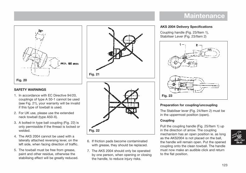
Maintenance
SAFETY WARNINGS
1. In accordance with EC Directive 94/20,couplings of type A 50-1 cannot be used(see Fig. 21), your warranty will be invalidif this type of towball is used.
2. For UK use, please use the extendedneck towball (type A50-X).
3. A bolted-in type ball coupling (Fig. 22) isonly permissible if the thread is locked orwelded.
4. The AKS 2004 cannot be used with alaterally attached reversing lever, on theleft side, when facing direction of traffic.
5. The towball must be free from grease,paint and other residue, otherwise thestabilising effect will be greatly reduced.
6. If friction pads become contaminatedwith grease, they should be replaced.
7. The AKS 2004 should only be operatedby one person, when opening or closingthe handle, to reduce injury risks.
AKS 2004 Delivery Specifications
Coupling handle (Fig. 23/Item 1),Stabiliser Lever (Fig. 23/Item 2)
Preparation for coupling/uncoupling
The Stabiliser lever (Fig. 24/Item 2) must bein the uppermost position (open).
Coupling
Pull the coupling handle (Fig. 25/Item 1) upin the direction of arrow. The couplingmechanism has an open position ie. as longas the AKS2004 is not placed on the ball,the handle will remain open. Put the openedcoupling onto the clean towball. The handlemust now make an audible click and returnto the flat position.
123
Fig. 20
Fig. 23
Fig. 21
Fig. 22

Maintenance
Warning: The coupling is correctly engagedwhen the green edge of the safety indicatorbutton is visible (Fig. 26/Item 3).
Stabiliser Unit
To operate the Stabiliser (once coupled tothe towball), simply press the stabiliser leverdown as far as it will go (Fig. 26/Item 2).
Uncoupling
Pull the stabiliser lever handle up as far as itwill go, open the coupling handle and lift theAKS2004 from the towball. With larger noseloads, coupling and uncoupling can be madeeasier by using the jockey wheel to assistlifting.
Please Note: The friction pads (Fig.27/1,2,3) are pressed against the towball andhence generate a stabilising/damping force.These pads are therefore subject to wearover time, however they will have a longservice life (circa.30,000 Miles), providedthey are well maintained and kept free ofgrease/dirt.
Checking the efficiency of the left/rightfriction pads
1. Couple up AKS 2004.
2. Open Stabiliser lever (Fig. 28/Item1).
3. Close Stabiliser lever until resistance isfelt (ie friction pads are in contact with theball but not yet under pressure).
4. If the arrow on the arm (Fig. 28/Item 4) isbefore or on the marked area (Fig.28/Item 2) the friction pads are still asnew (See A)
124
Fig. 24
Fig. 26
Fig. 27
Fig. 25

Maintenance
5. The arrow on the arm should lie betweenthe marked area on the soft dock (See B)
6. If the arrow on the plate reaches orpasses the marked area on the soft dockthen the friction pads need replacing (See C).
Please Note: It is not necessary to adjustthe friction pads
Manoeuvring
For easier manoeuvring (on campsites etc),pull the stabiliser lever to the ‘up’ position.
Please do not use the stabiliser lever as anmanoeuvring handle. Please use the handleson the Caravan or fit the AL-KOmanoeuvring handle to your jockey wheel(available separately).
1. During opening or closing, the AKS mustonly be operated by one person.
2. Press stabiliser lever down by hand forceonly DO NOT use your foot or anextension bar, this will damage thecomponents (Fig. 29).
3. When opening or closing thestabiliser lever, please ensure your handdoes not touch the coupling handle - youmay accidentally trap your fingers! (Fig.29).
Noises whilst driving
As a rule, the friction pads of the AKS 2004do not make a noise during driving. Anyclicking, creaking or squeaking noises thatdo arise may be due to the following:
a) Foreign bodies or dirt between the frictionpad and tow ball.
b) Dry operation of the drawshaft inside theoverrun device.
c) A detachable towball which has too muchplay in the locking mechanism.
125
Fig. 28
Fig. 29

MaintenanceRemedial Action
a) Clean the tow ball and friction pads bylightly rubbing the surface (100-120 gritemery paper).
b) Lubricate the drawshaft sleeve via thegrease nipples. In addition, push thegaiter forward and grease (DIN 51 825KTA 3K) the exposed part of the shaft(Fig. 30).
c) Visit a specialist workshop to have theball holding area checked for damageand the locking mechanism for function.If necessary, change the towball.
Servicing and Cleaning
Friction Pad Replacement (please replaceone at a time)
1. Uncouple AKS 2004.
2. Remove protective caps (Fig. 31/Item 1)with the aid of a small screwdriver.
3. Press worn out pad inwards and remove(use punch and hammer) (Fig. 31/2)
4. Insert new friction pad from below (afterfirst re-inserting shim washers if theywere present) and press in as far as it willgo (Fig. 31/Item 4 & Fig. 32).
Checking the efficiency of the front/rearfriction pads
1. Couple the AKS 2004 to the towball butdo not activate the stabiliser.
2. If a green indicator is visible (on thehandle), then the AKS 2004 is in a newcondition or the pads and towball arewithin the permissible limits (Fig. 33/Item2).
3. If only a red indicator is visible (Fig.34/Item 3), then this may have thefollowing causes:
a) AKS 2004 is okay but the towball hasreached the lowest limit of 49.61mm
b) AKS 2004 shows signs of wear
c) Towball is in a new condition (50mm)but the front/rear friction pads show ahigh degree of wear.
Establish the diameterof the towball so thatconclusions may bedrawn as to the wearof the friction pads(ball diameter mustnot be less than49.61mm)
126
Fig. 30
Fig. 31
Fig. 33 Fig. 34
Fig. 32

MaintenanceFriction Pad Replacement (Front/Rear only)
1. Uncouple the AKS 2004
2. Remove the rubber soft dock (pull up andoff) Fig. 35/Item 1 & Fig 36.
3. Press the safety indicator outwards andsecure with SW14 hex. spanner (notincluded), (Fig. 35/Item 2).
4. Remove cheese-head screws (Fig. 35/item 3 & Fig 36), using special torx tool.
5. Press friction lining recess (Fig. 35/Item 4)inwards and pull down and out.
6. Open coupling handle (Fig. 35/Item 8).
7. Remove countersunk head cap screwusing special torx tool (Fig. 35/Item 5 &Fig. 37).
8. Press friction pad inwards with ascrewdriver and remove from ball cup.
9. Fitment of new linings takes place inreverse. Tighten screws 3 & 5 to 5 Nm.
10) Replace rubber soft dock, insert topsection first then bottom.
Important Maintenance and CleaningAdvice:
1. The towball should be cleaned regularlyto remove grease or other residue, theuse of Thinners, White Spirit or BrakeCleaner is recommended - otherwise thestabilising effect will be severely reduced.
2. If friction pads are contaminated, theyshould not be cleaned but replaced.
3. The surface of the towball must be free ofgrooves, rust or seizing marks.
4. Towballs coated (with paint or similar)must have this surface completelyremoved (use 100 or 120 grain emerypaper). If this is not done, increasedtowball wear will occur and may cause
damage to the AKS 2004 components.
5. In Winter, carefully spray only the visualindicator with de-icer.
Lubrication
Should lubrication of the stabiliser partsbecome necessary, then the following mustbe observed.
a) Clean all parts thoroughly.
b) Areas may only be covered with a thinfilm of grease (Fig. 38).
c) Use multipurpose grease DIN 51825 KTA3K.
Warning: When lubricating, ensure nonegets into the friction pad or towball holdingarea.
127
Fig. 35
Fig. 38
Fig. 36 Fig. 37

MaintenanceOverrun Devices
In the importance of Safety, pleasefamiliarise yourself with the operation of thisoverrun device BEFORE using yourcaravan/trailer.
Safety Precautions
When parking your tow vehicle andcaravan/trailer on site, you must apply thecaravan handbrake. If the unit is parked butdisconnected from the tow vehicle, it isstrongly recommended that each wheel ischocked using AL-KO or suitable wheelchocks.
If a ‘detachable’ type drawbar is fitted (aswith catering trailers). the drawbar must notbe removed from the trailer with the hand-brake applied.
Caution: Please note when parking thecaravan/ trailer, the wheelbrake auto-reverse mechanism will allow thecaravan/trailer to travel backwards forapproximately 25 cm (please allowsufficient clearance when parking).
Operation
AL-KO overrun devices are a mechanicaltype, using a hydraulic damper.
Coupling Up
Manoeuvre towing vehicle or trailer tocoupling point.
Overrun devices fitted with 50 mmcoupling head
Fully open coupling head handle and securehitch onto the towball. See pages 10 and123 (coupling up).
Thread the breakaway cable through thebreakaway cable guide provided (Fig. 40)and connect it to attachment point providedon towing bracket (Fig. 39). Please refer to‘Braked Trailers Use of Breakaway Cables’for further detail.
Caution: The breakaway cable operates thehandbrake (emergency brake), in the eventof the caravan/trailer becoming detachedfrom the towing vehicle during towing. Forthis emergency brake to work correctly, it isabsolutely essential that the following pointsare observed:
1. The breakaway cable MUST run throughthe breakaway cable guide.
2. The breakaway cable MUST NOT bewrapped around the jockey wheel, as thisdisables the emergency brake (Fig. 41).
3. The cable MUST run as straight aspossible and not be restricted.
4. Ensure the cable is long enough to allowfor cornering and will not become taut orsnag during use, as this could result inthe handbrake operating whilst towing.
Please refer to ‘Braked Trailers Use ofBreakaway Cables’ Information sheet,supplied with your caravan/trailer.
128
Fig. 39
Fig. 40 Fig. 41

Maintenance
129
Overrun device fitted with Eye End
Lock the eye end into the eye end jawassembly and see operating instructions forvehicles fitted with eye end jaw assembly.
Overrun Device Fitted with 50 mmCoupling Head
Connect trailer electric plug controlling lightsand indicators etc. into towing vehiclesocket.
Wind the jockey wheel up fully and clampsecurely in position, ensuring that it does notfoul the brake rod or breakaway cable.
Ensure handbrake is fully off by pushing itfully down (Figs. 42-46).
Remove wheel chocks if fitted and stowsafely.
Caution: Failure to comply with this couldresult in the brakes overheating.
Coupling Up (Euro-Overrun Devices)
Fully retract Jockey Wheel inner tube so thatit locks against Jockey Wheel outer tube.
Slacken Jockey Wheel Clamp handle andraise complete assembly through cutout inbody to its highest position (ensure it doesn’tcome into contact with the brake rodassembly), fully tighten Jockey Wheel Clamphandle to ensure the Jockey Wheel is firmlyheld in position (Fig. 45).
Fig. 42
Fig. 43
Fig. 44
Fig. 45
Fig. 46

MaintenanceUncoupling (All Types)
Secure caravan/trailer by chocking bothwheels. Apply handbrake fully. There are 4different handbrake systems (See Figs 42-46). With all four systems please observe thefollowing:
Handbrake Lever With Gas Strut (Fig. 42)
Ensure handbrake is fully applied (ashighlighted). This will ensure that the gasstrut will automatically re-apply the wheelbrakes if the trailer starts to roll backwards.
To Release
Press the handbrake push button fully homeand firmly press the handbrake lever backinto the off position (handbrake horizontal).
Caution: If the handbrake is not fullyapplied as detailed above, there is dangerthat the trailer could roll backwards!
Caution: The brake rod must not be undertension/bowed when the handbrake isdisengaged, otherwise the breakawaymechanism will not function.
Handbrake Lever With Spring Cylinder(Fig. 43)
Apply handbrake fully ensuring thathandbrake is in the vertical position. This willensure that the spring cylinder energy storeis fully loaded and will automatically re-applythe wheel brakes if the trailer starts to rollbackwards.
Caution: If the handbrake is not fullyapplied as detailed above, there is dangerthat the trailer could roll backwards!
Automatic Handbrake Lever (Fig. 44)
Ensure handbrake is fully applied (ashighlighted). This will ensure that the gasstrut or spring cylinder will automatically re-apply the wheel brakes if the trailer starts toroll backwards.
Caution: If the handbrake is not fullyapplied as detailed above, there is dangerthat that the trailer could roll backwards!
To Release
Firmly push the handbrake lever back intothe off position (Handbrake horizontal).
Handbrake Lever With Spring Cylinderand Gas Strut (Fig. 46), normally fitted tocommercial units:
Ensure handbrake is fully applied (asdescribed). This will ensure that the gas strutor spring cylinder will automatically re-applythe wheel brakes if trailer starts to rollbackwards.
Caution: If the handbrake is not fullyapplied as detailed above, there is dangerthat the trailer could roll backwards!
To Release
Press the handbrake push button fully homeand firmly press the handbrake lever backinto the off position (handbrake horizontal).
Servicing
Every 10,000 - 15,000 Km or every 12months: Lubricate/grease all sliding andmoving parts of the overrun device as showin Fig. 47.
Recommended lubricant. General purposegrease to DIN 51825 KTA 3KA.
130
Fig. 47
Maintenance
131
Servicing and care of hot dip galvanisedparts
The formation of white rust is only a surfacecoating and has no adverse effect on theanti-corrosion properties of galvanising. Inorder to minimise the potential for theformation of white rust the followingprecautions should be taken:
- Ensure there is adequate air circulationwhen storing hot dip-galvanised parts.
- After winter journeys it is recommendedthat surfaces are washed with cleanwater.
Spare Parts
Spare parts are safety critical parts! For thisreason when fitting spare parts in ourproducts we recommend the use of originalAL-KO parts or those parts that we haveexplicitly approved. The reliability, safety andsuitability of parts designed especially forour products, has been determined using aspecial test procedure. In spite of constantlymonitoring the market we are unable toassess or vouch for other products.
If repair work or servicing is required, AL-KOhave a large network of AL-KO servicestations throughout Europe. To establish thecorrect spare parts required you shouldalways quote the model and type of overrundevice in question along with the ETI No.which is stamped into the overrun device
housing. The ETI number for the EuroOverrun can be found on the handbrakelever (See Fig. 45).
For Troubleshooting and Fault Finding,please see Table 3 on Page 132.

MaintenanceTrouble Shooting & Fault Finding
Table 1 Axles
132
Poor Braking
Difficulty in Reversing
Brakes Overheating
Handbrake Force Low
Uncomfortable ride orUneven Braking
Fault
Linings worn or damaged.
Brake Linings not bedded in.
Brake set up incorrect.
Braking system set too tightly.
Auto-Reverse lever too stiff.
Incorrect setting.
Braking system not fully released.
Overrun lever stuck.
Damage or Corrosion to braking system
Incorrect setting of the brakes.
Linings not bedded in.
Loose braking adjustment.
Damper defective.
Axle shock absorbers defective.
Replace Brake Linings.
Will pass after braking a few times.
Reset Brakes as page 117 & ensure system is lubricated.
Reset Brakes as page 117.
Lubricate and free off Reverse Lever.
Reset Brakes as page 117.
Check Handbrake has been released & the system is running freely.
Lubricate and free off Reverse Lever.
Check system as page 117 and repair or renew parts as necessary.
Reset brakes as page 117 and lubricate as necessary.
Will pass after braking a few times.
Reset brakes as page 117.
Check and replace damper if necessary.
Replace shock absorber.
Cause Remedy

Maintenance
133
Table 2 Coupling Heads
Coupling does not engageonto ball
Difficulty in Uncoupling
Too much play in thecoupling
Fault
Ball diameter too large. Ball could be damaged or deformed. Coupling head dirty or defective.
Ball damaged or deformed. Coupling damaged or deformed. Coupling head under pressure from damper.
Coupling damaged or deformed Ball too small
Change ball to correct size.Fit new ball.Clean & Lubricate coupling and replace if necessary.
Fit new ball.Replace if necessary.Pull forward a few inches to to relieve pressure
Replace if necessary.Fit new ball.
Cause Remedy
Table 3 Overrun Devices
Poor Braking
Brakes Overheating DuringTowing
Handbrake Force Low
Brakes Apply DuringDeceleration or Downhill Travel.
Fault
Overrun shaft tight. Overrun shaft corroded. Body housing damaged.
Handbrake not fully released. Braking system incorrectly set. Incorrect attachment of breakaway cable.
Defective gas strut. Incorrect setting of spring cylinder.
Overrun damper is defective.
Lubricate overrun shaft and replace any damaged parts.
Release handbrake.Reset brakes as page 117.Ensure correct attachment as listed on page ? or refer to Braked TrailersUse of Breakaway Cables sheet.
Replace gas strut.Reset spring cylinder as page 117.
Replace the overrun damper.
Cause Remedy

MaintenanceACCESSORIES
Corner Steadies
Corner Steadies are as stated, for thepurpose of steadying the caravan corners.They are NOT JACKS AND SHOULD NEVERBE USED AS SUCH. The screw and pivotpins should be lubricated periodically toensure their satisfactory operation. (See alsoJack Operation).
Shock Absorbers
All AL-KO chassis have pre punched holesto accommodate Shock Absorbers, in frontof the axle. On the Euro-Axle System, axleswing arms have a removable rectangularplastic cap exposing a slot to accommodateretro-fit brackets for the Octagon ShockAbsorbers. (See Accessory Price List). DeltaAxles have Shock Absorbers fitted asstandard which MUST NOT BE REMOVED.
Stabilisers
AL-KO overruns can be fitted with a range ofAL-KO Stabiliser devices (if not already fittedas standard), dependent on the maximumgross weight of the caravan. AL-KOstabilisers operate on a friction type basis,whereby friction pads grip onto a Dry,Grease Free Towball. It is important to notethat the AKS range of stabilisers are suitablefor use with swan neck, fixed or detachabletype towbars or the special AL-KO ExtendedNeck Bolt-On Towball. We do not approve
the use of any other bolt-on type towball,other than the AL-KO Towball. Failure to usethe correct towball may result in productfailure and will invalid your warranty.
The AKS range is available in three differentmodels: The AKS 1300 is suitable forcaravans up to a maximum gross weight of1360 Kg, the AKS 2700 up to 2700 Kg andthe new AKS 2004 up to 2000 Kg. EachStabiliser can also be retro-fitted with an AL-KO Security Device and Safety ball, toensure maximum theft Deterrent (please seeour accessory price list for further details).All ‘Red’ coloured AL-KO Security Deviceshave full TUV and Sold Secure Approvalsand are available from most good caravandealers or direct from AL-KO Mail Order on0800 074 4334.
AKS 1300 &SecurityDevice
AKS 2700 &SecurityDevice
AKS 2004 &SecurityDevice
Road Wheels
In most instances the road wheels and tyresare supplied by the Caravan Manufacturer.The condition of wheels and tyres should bechecked regularly, particularly for distortionof flanges and the wheel dish. Wheels thatare damaged or distorted, or have wheel boltseatings cracked or deformed must not berepaired or used in service - these mustbe replaced.
Important: Standard AL-KO caravan chassisuse M12 wheel bolts. These must alwaysonly be tightened to the correct torquesetting of 88 Nm (65 lbs/ft), in sequence, (i.e.North, South, East, West); NEVER clock oranti-clockwise. ALWAYS use a calibratedtorque wrench, do not use a corner steadybrace, power or electric wrench. It is asdangerous to overtighten wheel bolts as it isto not tighten them sufficiently.
Important: The torque settings should be re-checked after 50 Km.
If other wheel bolts are used please ensurethe torque settings are as follows:
134
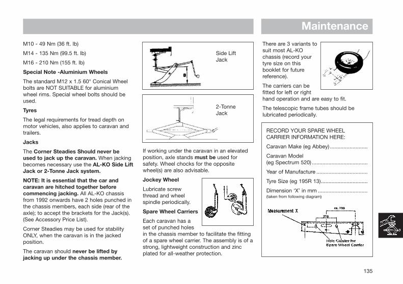
M10 - 49 Nm (36 ft. lb)
M14 - 135 Nm (99.5 ft. lb)
M16 - 210 Nm (155 ft. lb)
Special Note -Aluminium Wheels
The standard M12 x 1.5 60° Conical Wheelbolts are NOT SUITABLE for aluminiumwheel rims. Special wheel bolts should beused.
Tyres
The legal requirements for tread depth onmotor vehicles, also applies to caravan andtrailers.
Jacks
The Corner Steadies Should never beused to jack up the caravan. When jackingbecomes necessary use the AL-KO Side LiftJack or 2-Tonne Jack system.
NOTE: It is essential that the car andcaravan are hitched together beforecommencing jacking. All AL-KO chassisfrom 1992 onwards have 2 holes punched inthe chassis members, each side (rear of theaxle); to accept the brackets for the Jack(s).(See Accessory Price List).
Corner Steadies may be used for stabilityONLY, when the caravan is in the jackedposition.
The caravan should never be lifted byjacking up under the chassis member.
Side LiftJack
2-TonneJack
If working under the caravan in an elevatedposition, axle stands must be used forsafety. Wheel chocks for the oppositewheel(s) are also advisable.
Jockey Wheel
Lubricate screwthread and wheelspindle periodically.
Spare Wheel Carriers
Each caravan has aset of punched holesin the chassis member to facilitate the fittingof a spare wheel carrier. The assembly is of astrong, lightweight construction and zincplated for all-weather protection.
There are 3 variants tosuit most AL-KOchassis (record yourtyre size on thisbooklet for futurereference).
The carriers can befitted for left or righthand operation and are easy to fit.
The telescopic frame tubes should belubricated periodically.
RECORD YOUR SPARE WHEEL CARRIER INFORMATION HERE:
Caravan Make (eg Abbey) .........................
Caravan Model (eg Spectrum 520) .....................................
Year of Manufacture ..................................
Tyre Size (eg 195R 13)...............................
Dimension ‘X’ in mm .................................(taken from following diagram)
Maintenance
135

GENERALDATA
Fault Finding ......................................................................... 138Water .................................................................................. 138Gas ..................................................................................... 140Cassette Toilet .................................................................... 141
Useful Information ............................................................... 142Owners Club ...................................................................... 142Spares and After Sales ...................................................... 142Repair Facilities .................................................................. 142Caravan Clubs......................................................................143Motoring Associations .........................................................143Trade Association.................................................................143CRIS .....................................................................................143

Water not flowing fromany tap when operatedbut pump runs
Problem
Freshwater tank empty Check
Pump wired in reverse Check wiring, refer to pump manufacturers instructions
Pump not primed Refer to pump manufacturers instructions
Pipe inlet or outlet pipe disconnected Check connections
Pump pipes restricted by kinking Check pipes run
Blockage in pump inlet or outlet pipe Check, starting inside freshwater tank
Blocked in-line filter of pump filter Dismantle and clean
Air leak in suction line to pump Check for bubbles & secure with clip
Possible Cause Remedy
Pump does not run Pump or tap incorrectly wired Refer to pump/tap manufacturers instructions
Pump fuse blown Check wiring connection and then replace with fuse of correct rating
Battery disconnected Check connections
Pump seized or overheated Refer to pump manufacturers servicing instructions
Pressure pump sensing switch may have failed Refer to pump manufacturers servicing instructions
Contacts may be faulty Check contacts in plug and socket are clean and making contact
Wiring connections may be faulty Check wiring connections
On switched tap version, microswitch could be faulty Disconnect wires from microswitch and join together. If the pump operates, microswitch should be replaced
Water flows from cold tapbut not from hot
Feed pipe to water heater incorrectly connected to Refer to installation instructionsthe heater outlet
Blockage in hot pipeline Disconnect pipes and inspect
Heater inlet or outlet pipes kinked preventing flow Check and re-route if necessary. Ensure that hose is Carverrecommended type
Hot tap not connected Refer to installation manual
Hot tap failed or blocked Disconnect and inspect
Heater non-return valve jammed Seek service attention
Fault Finding
WATER
138

Fault Finding
139
Problem Possible Cause Remedy
Water flows from hot tapbut has reduced flow fromcold
Cold water pipe kinked preventing flow Check and re-route if necessary
Blockage in cold pipe line Disconnect pipes after 1st Y connector and check up to tap
Cold tap not connected Refer to installation instructions
Cold tap failed or blocked Disconnect and inspect
If a water filter is fitted, the cartridge is exhausted Replace cartridge
Reduced flow from bothhot and cold taps
Battery condition low causing pump to run slowly Check battery state of charge, refer to electrical supply note
If new taps have been fitted they may be restricting flow Disconnect and check that they have at least 1/4" (6.3mm) bore
Pump needs servicing Refer to pump servicing instructions
Partially blocked pump filter or in-line filter, if fitted Dismantle and clean if necessary
Pump outlet pipe kinked restricting flow Check and re-route if necessary
Water leak Check all water connections
Reduced flow fromeither tap
Y’ connector(s) fitted incorrectly Refer to installation instructions
Pipe kinking restricting flow Check and re-route if necessary
Bore size difference in taps Use taps of equal bore size
WATER (continued)
Warm water flows out ofcold tap
Hot water back-feeding into cold line, usually if mixer Fit non-return valve in cold supply, near taptap or single outlet hot and cold taps being used
If pump motor runssteadily and will not stop
Battery voltage may be too low (below 10.5 volts) Check that there is water in the container
Adjust switch and/or re-charge battery
Check all connections in pipework

Fault Finding
140
Hob does not light No gas Check level of gas in bottleCheck gas bottle valve is onCheck gas taps are on
Air in pipe Purge systemRefer to hob manufacturers instructions
Oven does not light No gas Check level of gas in bottleCheck gas bottle valve is onCheck gas taps are on
Air in pipe Purge systemRefer to oven manufacturers instructions
Space heater or centralheating
No gas Check level of gas in bottleCheck gas bottle valve is onCheck gas taps are onCheck exhaust outlet is clear
Over gassed Turn off appliance, wait 2 minutes and try againAir in pipe Purge system
Refer to space heater or central heating boiler manufacturers instructions
GAS
Fridge does not light No gas Check level of gas in bottleCheck gas bottle valve is onCheck gas taps are on
Air in pipe Purge systemRefer to fridge manufacturers instructions
Water heater does notlight
No gas Check level of gas in bottleCheck gas bottle valve is onCheck gas taps are on
Air in pipe Purge systemRefer to water heater manufacturers instructions
Problem Possible Cause Remedy

Problem
Fault Finding
141
Bowl does not drain whentoilet is flushed.
Cassette is overfilled
DO NOT REMOVE CASSETTE. While inside the caravan turn flush knob anti-clockwise to open valve blade andleave it in the open position.Open access door on side of caravan. Rotate pour-out spout outward. Place appropriate size container under spout cap. Remove cap carefully. Allow bowl contents to drain into container. This will lower the water level in the bowl.Replace cap and return pour-out spout to stored position. DO NOT REMOVE CASSETTE.Go inside the caravan and turn the flush knob clockwise to close valve blade. Now, the cassette may be removed following the normal removal and emptying procedure.
Odours Use proper amount of holding tank deodourant specified on bottle.
CASSETTE TOILET
Toilet tissue does not fitinto compartment.
Since some tissues are supplied on larger rolls, it may be necessary to use some tissue before storing into compartment.
Soiled bowl after flushing Partially fill bowl to cover soiled portion of bowl. Next flush will dissolve waste. Tip: Leave valve blade open during use.
No power to add water totoilet bowl
Check cassette safety sensor switch and fuse-holder for proper engagement and operation.Note: Cassette has to be removed to reach switch and fuse.Insert cassette and try adding water to toilet bowl.Toilet can be flushed manually. Add water. Add water to bowl from a separate container. Turn flush knob anti-clockwise to open valve blade. Turn clockwise to close valve blade.
Cassette cannot beremoved
Check for obstacles under retaining clip. Depress retaining clip several times to check operation. Remove cassette.Flush knob and valve blade in partial open position. Close valve blade by moving knob clockwise.CAUTION: If valve blade is open during cassette removal, severe damage to system can occur. Never force insertion or removal of the cassette tank.
Valve blade mechanismsticks or is hard to open
Spray light film of silicone on blade.
Major unit malfunction Contact your original Caravan Dealer.
Remedy

Useful InformationOWNERS CLUBThe Owners Club is a completelyindependent organisation run for the benefitof the caravan owners. They have numerousrallies during the year in various parts of thecountry and every third year there is a‘Works Rally’ where owners have theopportunity to visit the factory. Apart fromthe friendliness and companionship the Clubgenerates it is also actively engaged incharity work for those less fortunate thanourselves. The address of the Secretary ofthe Owners Club can be obtained fromSupercare (SML Ltd), Tel: 01482 875740 orfrom the Swift Group website.
SPARES AND AFTER SALESSUPERCAREThere are numerous items available fromyour dealer ranging from door catchesthrough to spare wheels and touch-uppaints. Please note that all after salesenquiries must be directed through yoursupplying dealer. The after sales service atthe factory is geared to support our dealernetwork as is the service provided byappliance manufacturers.
In the interest of safety, replacement partsfor an appliance shall conform to theappliance manufacturers specifications andshould be fitted by them or their authorisedagents.
Note: Please remember to quote chassisnumber when ordering any items from yourdealer.
Customer CareTel: 01482 875740Fax: 01482 840082
NOTE:The times for contacting Customer Care bytelephone are:
9am to 4pm Monday to Thursday.9am to 12.45pm Friday.
Swift Group Websitewww.swiftleisure.co.uk
Swift Group E-Mail [email protected]
REPAIR FACILITIESShould you be unfortunate enough to suffera major accident with your caravan it iscomforting to know that we have acompletely separate repair shop facilitywhere their fully trained experts will undertake all types of major damage repair work.
Repairs of a minor nature should be referredfirst to your local dealer.
142

Useful InformationThe enjoyment of caravanning can be greatly enhanced by membership of one ormore of the various caravanning, motoringand holiday clubs. Here are some usefuladdresses:
CARAVAN CLUBS
The Caravan Club,East Grinstead House,East GrinsteadWest Sussex, RH19 IUATel: 01342 326944www.caravanclub.co.uk
The Camping and Caravanning Club,Greenfields House,Westwood Way,Coventry,West Midlands.Tel: 01203 694995www.campingandcaravanningclub.co.uk
MOTORING ASSOCIATIONS
Automobile Association (AA)Fanum House,Basingstoke,Hants. RG1 2EATel: 0990 448866www.theaa.co.uke-mail: [email protected]
RAC Motoring ServicesRAC House,M1 Cross,Brent Terrace,London, NW2 1BXTel: 0990 722722www.rac.co.uk
Green Flag National BreakdownPO Box 300,1, Cote Lane,Leeds, LS99 2LZTel: 0345 670345
TRADE ASSOCIATION
National Caravan CouncilCatherine House,Victoria Road,Aldershot,Hampshire, GU11 1SSTel: 01252 318251www.martex.co.uk/ncce-mail: [email protected]
CRIS
HPI EquifaxDolphin House,New Street,Salisbury,Wiltshire SP1 2TBTel: 01722 411430/422422
Swift Group LimitedDunswell Road, Cottingham,East Yorkshire HU16 4JXTel: (01482) 875740e-mail: [email protected] site: www.swiftleisure.co.uk
© 2000 SWIFT GROUP LTD
143

Index
A Accessories ...................................134Air Conditioning.............................106Alarm System ..................................47Alde Heating System.......................59AL-KO Running Gear.....................113Arrival on Site ..................................17Ash Framed Doors ........................107Awnings .........................................108
B Barbeque Point..............................101Battery .............................................46Bedding .........................................102Blinds.............................................104Blizzard Air Conditioner.................106Brake Linkages..............................118Braking System .............................117Breakaway Cable ............................13Bunks.............................................103
C Caravan Clubs...............................143Caravan Terms...................................2Cassette Toilets ...............................94Chassis Number ..............................22Children ...........................................21Comet Roma Single Lever
Mixer Tap......................................27Corner Steadies...............................10CRIS ..............................................143
D DoorsEntrance .....................................105Ash Framed................................107
Doorscreen ....................................104Driving Licence..................................4
E Electrical Control Module ................43Electrical Control Panels .................40Electricity Supply.............................34
Arrival on Site...............................34Consumption Figures...................37Generator .....................................46Mains Inlet Cable .........................36Overseas Connections.................3512V ...............................................49
Electrical Supply Module ...........42/44Escape Paths ..................................19
F Fault Finding..................................138AL-KO Running Gear .................132Cassette Toilet............................141Gas.............................................140Water ..........................................138
Fire ..................................................20Fire Extinguisher ..............................21Flyscreens......................................104Fumes..............................................22Fuses (DC) .......................................45Fuses (road lights) ...........................43
G Gas Supply ......................................30Butane..........................................31Connection...................................33Fault Finding ..............................140Flue Installations ..........................33Gas Bottles ..................................31Hoses ...........................................31Precautions ..................................32Propane........................................32Regulator......................................31Safety Advice ...............................32Ventilation.....................................32
Generator Guidelines.......................46Glossary and Checklist .....................4Grill ..................................................91
H Habitation Relay ..............................46Handling ..........................................15Heating ............................................55Heki Rooflight ................................104Hob..................................................90Hotplates .........................................91
I Inboard Water Tanks........................26Insurance .........................................22
J Jacking Points .................................16Jockey Wheel ................................135
L Levelling...........................................17Loading and Distribution of Weight...7
M Maintenance ..................................110Exterior .......................................110Interior ........................................110Modifications/DIY.......................110Winterisation/Storage.................111
Microswitch Taps.............................27Mirrors .............................................15Motoring Associations...................143Motorway Driving ............................16Moving Off .......................................15
N Noseweight........................................4
O Omnivent Rooflight........................104Oven ................................................91Overseas Electrical Connections ....35Owners Club..................................142
P Passengers ......................................13Preparing for the Road......................7
Loading & Distribution of Weight ...7Other Considerations .....................9Pre-load Checklist..........................7Pre-tow Checklist and
Hitch Up....................................10Stability ..........................................8Towing Vehicle - Rear
Suspension .................................8Pullman Bunks...............................103
R Refrigerators ....................................68Dometic RM7271L, RM7275L,RM7291L, RM7295L, RM7361L, RM7365L, RM7401L and RM7405L......................................68Thetford Absorber ........................81RM4501........................................67
Reich Kama Single Lever Mixer Tap......................................28
Repair Facilities .............................142Reversing.........................................15Road Lighting ..................................13Rooflights ......................................104
S Safety and Security .........................19Security............................................22
Services ...........................................23Electricity......................................34Gas...............................................30Water ............................................24
Shock Absorbers...........................134Shower ..........................................107Smoke Alarm ...................................20Space Heaters.................................55Spares and After Sales..................142Speed Limits....................................15Stability..............................................8Stopping on a Hill............................17Stoves Hobs, Grills and Ovens .......90
T Tables ............................................107Taps .................................................27Thermal Insulation ...........................33Thermostat ......................................67Thetford Absorber Refrigerator .......72Thetford Cassette Porta Potti .........94Thetford Cassette C-200.................97Towing Code......................................2Towing Vehicle Terms ........................3Trade Associations ........................143Transformer/Charger Unit ................43Truma Compact Crystal 2 ...............25Truma Space Heaters......................55Truma Ultraheat Heating .................57Truma Ultrastore Water Heater........52Truma Waterline...............................26TV Inlet...........................................101Tyres ..............................................135
V Ventilation ........................................21
W Water ...............................................24Heater...........................................52Pumps ..........................................25Tanks and Systems......................26
Weights..............................................2Wheels......................................10/134
Changing......................................16Rims .............................................10Torque ..........................................16
Windows........................................104Winter Maintenance
and Storage ...............................111
146
NCC Approved
All Swift Group models have been certified by the National Caravan Council for compliancewith stringent European Standards, British Legislation and industry set Codes of Practicespecifically relating to health and safety issues. The approval process covers the testing andinspection of critical areas of the product from fire safety, weights and dimensions, to gas,electrics and ventilation. Every Swift caravan carries the "NCC Approved Caravan" badge.The NCC also conduct unannounced inspections at the Swift factory to ensure continuedcompliance. NCC Approval gives you peace of mind that your caravan is legal and safe.
Quality with Style
Swift Caravans, Dunswell Road, Cottingham, East Yorkshire HU16 4JX. Tel: 01482 875740 Fax: 01482 840082
e-mail: [email protected] website: www.swiftcaravans.co.uk
Issued September 2003 1051572000


