Electric cylinders EPCO, with spindle drive TOC Bookmark ...
39
Electric cylinders EPCO, with spindle drive
Transcript of Electric cylinders EPCO, with spindle drive TOC Bookmark ...
Electric cylinders EPCO, with spindle drive
TOC BookmarkElectric cylinders EPCO, with spindle driveCharacteristics
Type codes
Data sheet
Technical data
Materials
Dimensions
Ordering data
Ordering data – Modular product system
Accessories
Foot mounting
Flange mounting
Swivel mounting
Adapter kit
Trunnion flange
Trunnion support
Swivel flange
Rod eye
Self-aligning rod coupler
Coupling piece
Rod clevis
Guide unit
Proximity switch
Connecting cable
Sensor mounting
Sensor rail
Mounting kit
Motor cable
Encoder cable
Motor controller
2 d Internet: www.festo.com/catalogue/... Subject to change – 2021/08
Electric cylinders EPCO, with spindle drive
Characteristics
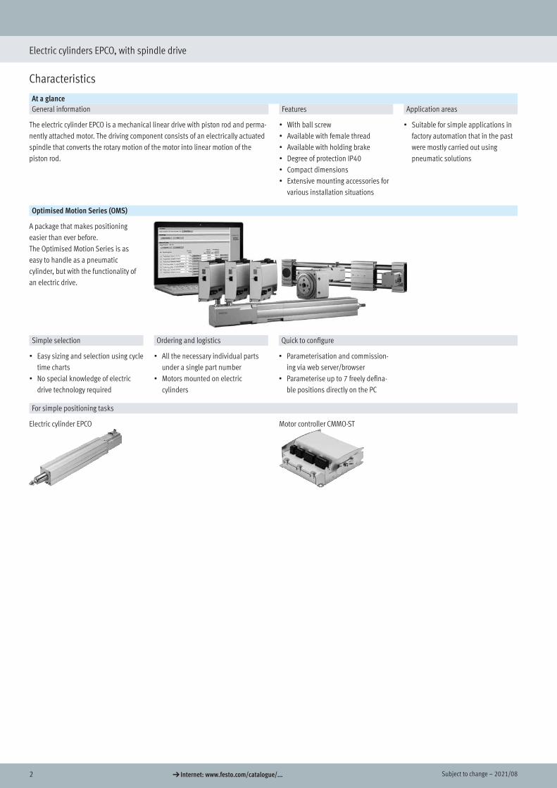
At a glanceGeneral information Features Application areas
The electric cylinder EPCO is a mechanical linear drive with piston rod and perma-nently attached motor. The driving component consists of an electrically actuated spindle that converts the rotary motion of the motor into linear motion of the piston rod.
• With ball screw• Available with female thread• Available with holding brake• Degree of protection IP40• Compact dimensions• Extensive mounting accessories for
various installation situations
• Suitable for simple applications in factory automation that in the past were mostly carried out using pneumatic solutions
Optimised Motion Series (OMS)
A package that makes positioning easier than ever before.The Optimised Motion Series is as easy to handle as a pneumatic cylinder, but with the functionality of an electric drive.
Simple selection Ordering and logistics Quick to configure
• Easy sizing and selection using cycle time charts
• No special knowledge of electric drive technology required
• All the necessary individual parts under a single part number
• Motors mounted on electric cylinders
• Parameterisation and commission-ing via web server/browser
• Parameterise up to 7 freely defina-ble positions directly on the PC
For simple positioning tasks
Electric cylinder EPCO Motor controller CMMO-ST
Characteristics
32021/08 – Subject to change d Internet: www.festo.com/catalogue/...
Electric cylinders EPCO, with spindle drive
Characteristics
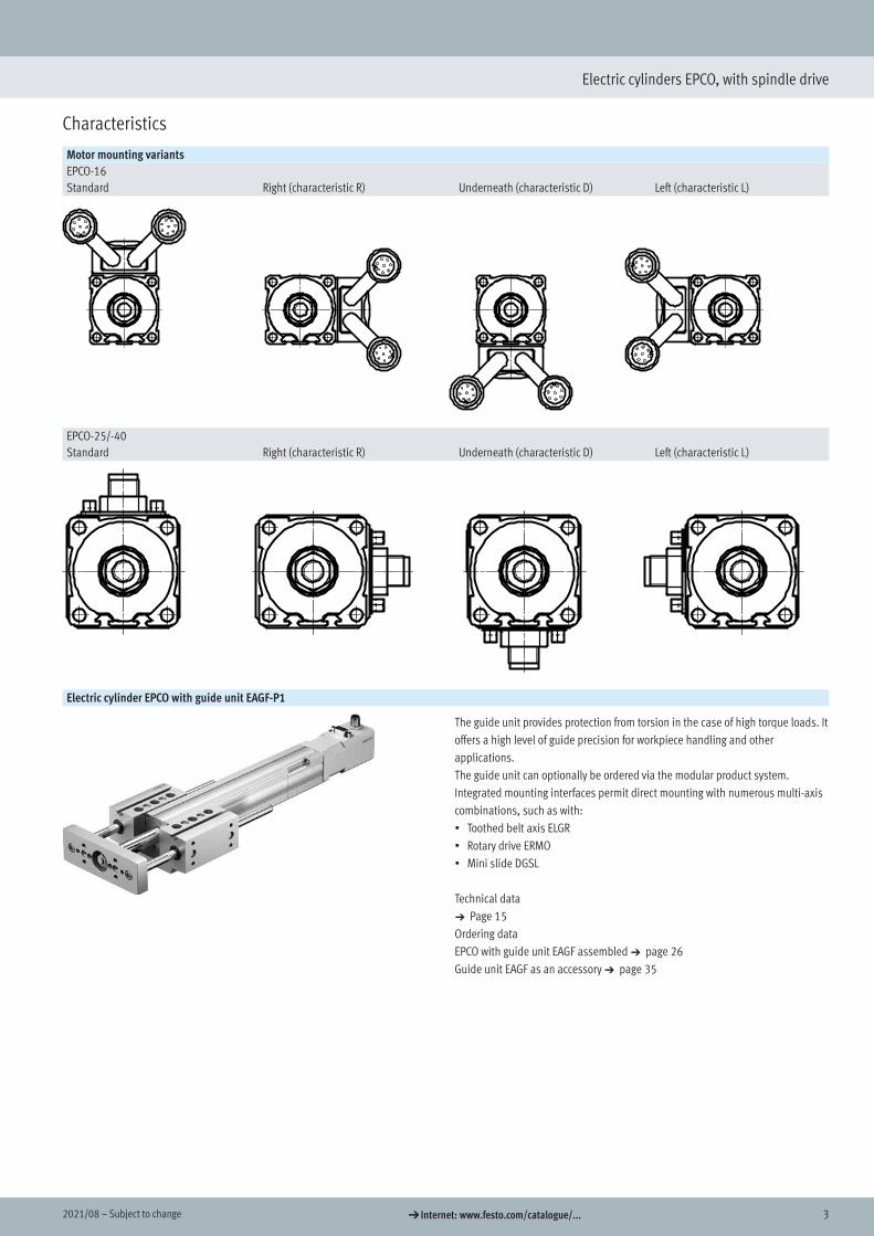
Motor mounting variantsEPCO-16Standard Right (characteristic R) Underneath (characteristic D) Left (characteristic L)
EPCO-25/-40Standard Right (characteristic R) Underneath (characteristic D) Left (characteristic L)
Electric cylinder EPCO with guide unit EAGF-P1
The guide unit provides protection from torsion in the case of high torque loads. It offers a high level of guide precision for workpiece handling and other applications.The guide unit can optionally be ordered via the modular product system.Integrated mounting interfaces permit direct mounting with numerous multi-axis combinations, such as with:• Toothed belt axis ELGR• Rotary drive ERMO• Mini slide DGSL
Technical data a Page 15Ordering data EPCO with guide unit EAGF assembled a page 26 Guide unit EAGF as an accessory a page 35
4 d Internet: www.festo.com/catalogue/... Subject to change – 2021/08
Electric cylinders EPCO, with spindle drive
Characteristics
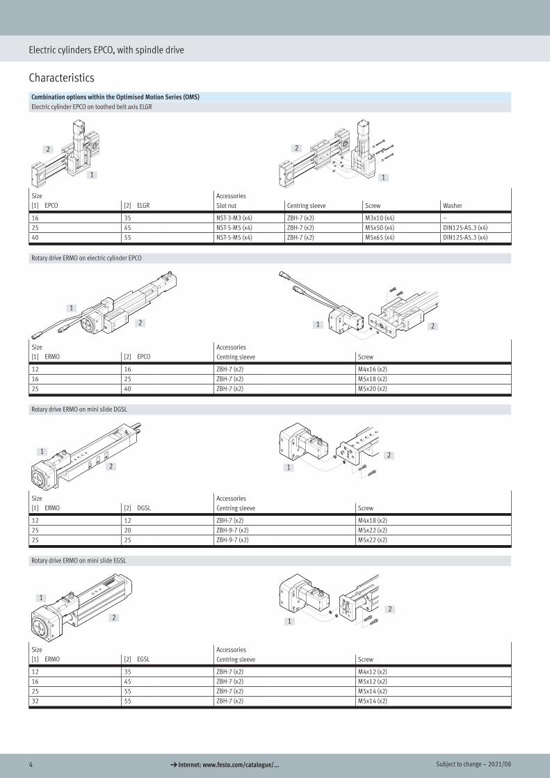
Combination options within the Optimised Motion Series (OMS)Electric cylinder EPCO on toothed belt axis ELGR
1
2
1
2
Size Accessories[1] EPCO [2] ELGR Slot nut Centring sleeve Screw Washer
16 35 NST-3-M3 (x4) ZBH-7 (x2) M3x10 (x4) –25 45 NST-5-M5 (x4) ZBH-7 (x2) M5x50 (x4) DIN125-A5.3 (x4)40 55 NST-5-M5 (x4) ZBH-7 (x2) M5x65 (x4) DIN125-A5.3 (x4)
Rotary drive ERMO on electric cylinder EPCO
1
2 1 2
Size Accessories[1] ERMO [2] EPCO Centring sleeve Screw
12 16 ZBH-7 (x2) M4x16 (x2)16 25 ZBH-7 (x2) M5x18 (x2)25 40 ZBH-7 (x2) M5x20 (x2)
Rotary drive ERMO on mini slide DGSL
1
2 1
2
Size Accessories[1] ERMO [2] DGSL Centring sleeve Screw
12 12 ZBH-7 (x2) M4x18 (x2)25 20 ZBH-9-7 (x2) M5x22 (x2)25 25 ZBH-9-7 (x2) M5x22 (x2)
Rotary drive ERMO on mini slide EGSL
1
2 1
2
Size Accessories[1] ERMO [2] EGSL Centring sleeve Screw
12 35 ZBH-7 (x2) M4x12 (x2)16 45 ZBH-7 (x2) M5x12 (x2)25 55 ZBH-7 (x2) M5x14 (x2)32 55 ZBH-7 (x2) M5x14 (x2)
52021/08 – Subject to change d Internet: www.festo.com/catalogue/...
Electric cylinders EPCO, with spindle drive
Characteristics
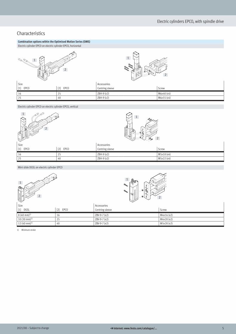
Combination options within the Optimised Motion Series (OMS)Electric cylinder EPCO on electric cylinder EPCO, horizontal
1
2
1
2
Size Accessories[1] EPCO [2] EPCO Centring sleeve Screw
16 25 ZBH-9 (x2) M6x40 (x4)25 40 ZBH-9 (x2) M6x55 (x4)
Electric cylinder EPCO on electric cylinder EPCO, vertical
1
2
1
2
Size Accessories[1] EPCO [2] EPCO Centring sleeve Screw
16 25 ZBH-9 (x2) M5x18 (x4)25 40 ZBH-9 (x2) M5x22 (x4)
Mini slide DGSL on electric cylinder EPCO
1
2
1
2
Size Accessories[1] DGSL [2] EPCO Centring sleeve Screw
8 (40 mm)1) 16 ZBV-9-7 (x2) M4x16 (x2)10 (30 mm)1) 25 ZBV-9-7 (x2) M4x20 (x2)12 (40 mm)1) 40 ZBV-9-7 (x2) M5x20 (x2)
1) Minimum stroke

6 d Internet: www.festo.com/catalogue/... Subject to change – 2021/08
Electric cylinders EPCO, with spindle drive
Peripherals overview
24
18
19
20
21
4
1
23
8
9
10
11
12
2223
5
67
13
14
916
17
3
15
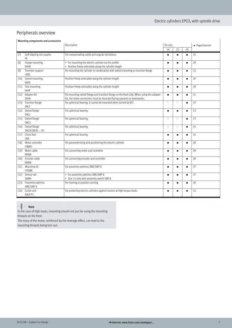
Mounting components and accessoriesDescription For size a Page/Internet
16 25 40
[1] Right angle clevis footLQG
For rod eye SGS – – h 34
[2] Rod clevisSGA
For rod eye SGS, for swivelling cylinder mounting – – h 35
[3] Clevis footLBG
For rod eye SGS, for spherical bearing – – h 34
[4] Rod eyeSGS/CRSGS
For spherical bearing h h h 35
[5] Coupling pieceKSG
For compensating radial deviations – – h 35
[6] Rod clevisSG/CRSG
Permits a swivelling movement of the cylinder in one plane h h h 35
72021/08 – Subject to change d Internet: www.festo.com/catalogue/...
Electric cylinders EPCO, with spindle drive
Peripherals overview
Mounting components and accessoriesDescription For size a Page/Internet
16 25 40
[7] Self-aligning rod couplerFK
For compensating radial and angular deviations h h h 35
[8] Flange mountingEAHH
• For mounting the electric cylinder via the profile• Position freely selectable along the cylinder length
h h h 29
[9] Trunnion supportLNZG
For mounting the cylinder in combination with swivel mounting or trunnion flange h h h 32
[10] Swivel mountingEAHS
Position freely selectable along the cylinder length h h h 30
[11] Foot mountingEAHF
Position freely selectable along the cylinder length h h h 28
[12] Adapter kitEAHA
For mounting swivel flange and trunnion flange on the front side. When using the adapter kit, the motor connection must be mounted facing upwards or downwards.
h h h 31
[13] Trunnion flangeZNCF
For spherical bearing. It cannot be mounted when turned by 90°. – – h 32
[14] Swivel flangeSNCL
For spherical bearing h h h 33
[15] Swivel flangeSNCS
For spherical bearing – – h 33
[16] Swivel flangeSNCB/SNCB-...-R3
For spherical bearing – – h 34
[17] Clevis footLBN
For spherical bearing h h h 34
[18] Motor controllerCMMO
For parameterising and positioning the electric cylinder h h h 38
[19] Motor cableNEBM
For connecting motor and controller h h h 38
[20] Encoder cableNEBM
For connecting encoder and controller h h h 38
[21] Mounting kitCRSMB
For proximity switches SME/SMT-8 h h h 37
[22] Sensor railSAMH
• For proximity switches SME/SMT-8• Size 25 only with proximity switch SMT-8
h h h 37
[23] Proximity switchesSME/SMT-8
For homing or position sensing h h h 36
[24] Guide unitEAGF-P1
For protecting electric cylinders against torsion at high torque loads h h h 35
H- - NoteIn the case of high loads, mounting should not just be using the mounting threads on the front.The mass of the motor, reinforced by the leverage effect, can lead to the mounting threads being torn out.
8 d Internet: www.festo.com/catalogue/... Subject to change – 2021/08
Electric cylinders EPCO, with spindle drive
Type codes
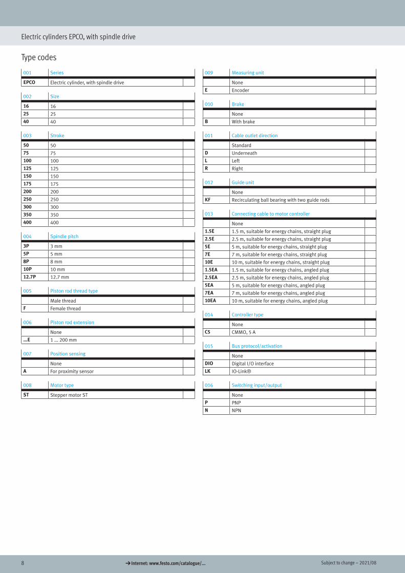
Type codes
001 Series
EPCO Electric cylinder, with spindle drive
002 Size
16 16
25 25
40 40
003 Stroke
50 50
75 75
100 100
125 125
150 150
175 175
200 200
250 250
300 300
350 350
400 400
004 Spindle pitch
3P 3 mm
5P 5 mm
8P 8 mm
10P 10 mm
12.7P 12.7 mm
005 Piston rod thread type
Male thread
F Female thread
006 Piston rod extension
None
...E 1 ... 200 mm
007 Position sensing
None
A For proximity sensor
008 Motor type
ST Stepper motor ST
009 Measuring unit
None
E Encoder
010 Brake
None
B With brake
011 Cable outlet direction
Standard
D Underneath
L Left
R Right
012 Guide unit
None
KF Recirculating ball bearing with two guide rods
013 Connecting cable to motor controller
None
1.5E 1.5 m, suitable for energy chains, straight plug
2.5E 2.5 m, suitable for energy chains, straight plug
5E 5 m, suitable for energy chains, straight plug
7E 7 m, suitable for energy chains, straight plug
10E 10 m, suitable for energy chains, straight plug
1.5EA 1.5 m, suitable for energy chains, angled plug
2.5EA 2.5 m, suitable for energy chains, angled plug
5EA 5 m, suitable for energy chains, angled plug
7EA 7 m, suitable for energy chains, angled plug
10EA 10 m, suitable for energy chains, angled plug
014 Controller type
None
C5 CMMO, 5 A
015 Bus protocol/activation
None
DIO Digital I/O interface
LK IO-Link®
016 Switching input/output
None
P PNP
N NPN
92021/08 – Subject to change d Internet: www.festo.com/catalogue/...
Electric cylinders EPCO, with spindle drive
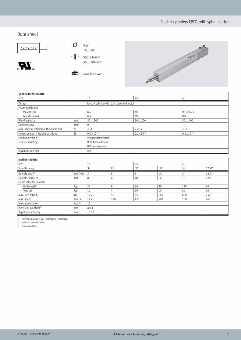
Data sheet
-N- Size 16 ... 40
-T- Stroke length 50 ... 400 mm
-É- www.festo.com
General technical dataSize 16 25 40
Design Electric cylinder with ball screw and motorPiston rod thread
Male thread M6 M8 M10x1.25Female thread M4 M6 M8
Working stroke [mm] 50 ... 200 50 ... 300 50 ... 400Stroke reserve [mm] 0Max. angle of rotation at the piston rod [°] š ±2 š ±1.5 š ±1Impact energy in the end positions [J] 0.1 x 10⁻³ 0.2 x 10⁻³ 0.4 x 10⁻³
Position sensing Via proximity switchType of mounting With female thread
With accessoriesMounting position Any
Mechanical dataSize 16 25 40Spindle design 3P 8P 3P 10P 5P 12.7P
Spindle pitch1) [mm/rev] 3 8 3 10 5 12.7Spindle diameter [mm] 8 8 10 10 12 12.7Guide value for payload
Horizontal2) [kg] 24 8 60 20 120 40Vertical [kg] 12 4 30 10 60 20
Max. feed force Fx [N] 125 50 350 105 650 250Max. speed [mm/s] 125 300 150 500 180 460Max. acceleration [m/s2] 10Reversing backlash3) [mm] š 0.1Repetition accuracy [mm] ±0.02
1) Nominal value varies due to component tolerances
2) Note max. transverse load
3) In new condition
Data sheet
Technical data
10 d Internet: www.festo.com/catalogue/... Subject to change – 2021/08
Electric cylinders EPCO, with spindle drive
Data sheet
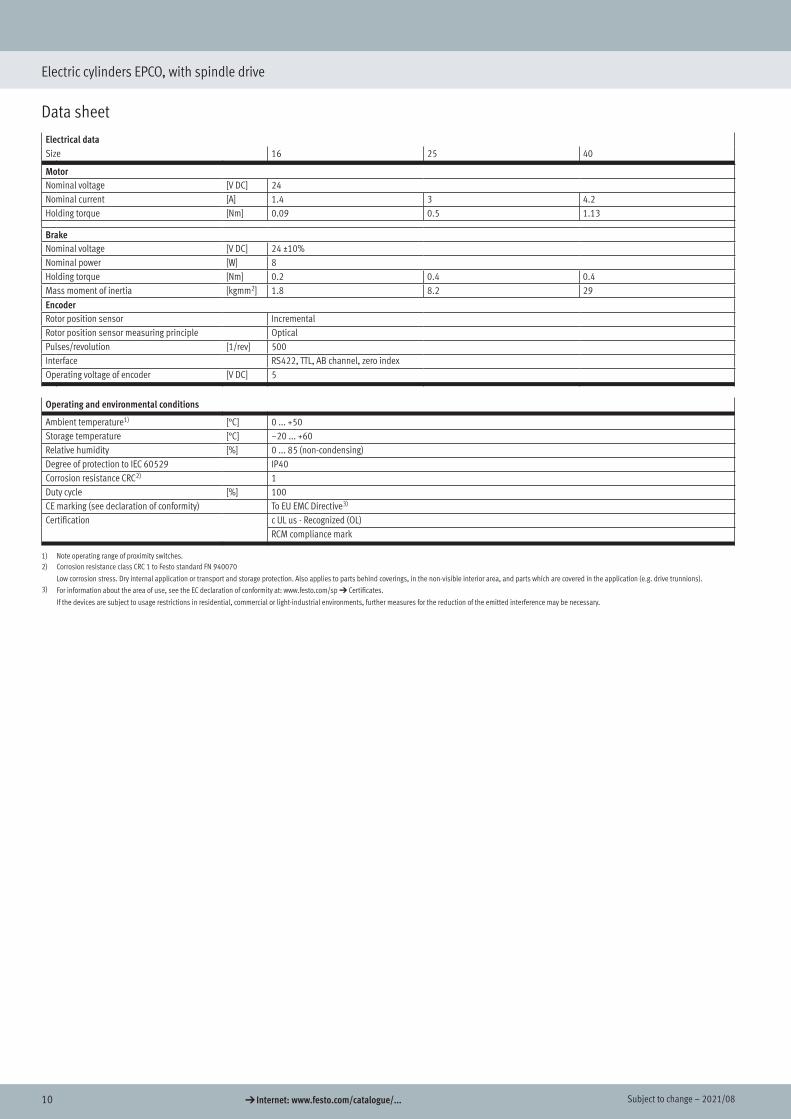
Electrical dataSize 16 25 40
MotorNominal voltage [V DC] 24Nominal current [A] 1.4 3 4.2Holding torque [Nm] 0.09 0.5 1.13
BrakeNominal voltage [V DC] 24 ±10%Nominal power [W] 8Holding torque [Nm] 0.2 0.4 0.4Mass moment of inertia [kgmm2] 1.8 8.2 29EncoderRotor position sensor IncrementalRotor position sensor measuring principle OpticalPulses/revolution [1/rev] 500Interface RS422, TTL, AB channel, zero indexOperating voltage of encoder [V DC] 5
Operating and environmental conditions
Ambient temperature1) [°C] 0 ... +50Storage temperature [°C] –20 ... +60Relative humidity [%] 0 ... 85 (non-condensing)Degree of protection to IEC 60529 IP40Corrosion resistance CRC2) 1Duty cycle [%] 100CE marking (see declaration of conformity) To EU EMC Directive3)
Certification c UL us - Recognized (OL)RCM compliance mark
1) Note operating range of proximity switches.2) Corrosion resistance class CRC 1 to Festo standard FN 940070
Low corrosion stress. Dry internal application or transport and storage protection. Also applies to parts behind coverings, in the non-visible interior area, and parts which are covered in the application (e.g. drive trunnions).3) For information about the area of use, see the EC declaration of conformity at: www.festo.com/sp d Certificates.
If the devices are subject to usage restrictions in residential, commercial or light-industrial environments, further measures for the reduction of the emitted interference may be necessary.
112021/08 – Subject to change d Internet: www.festo.com/catalogue/...
Electric cylinders EPCO, with spindle drive
Data sheet
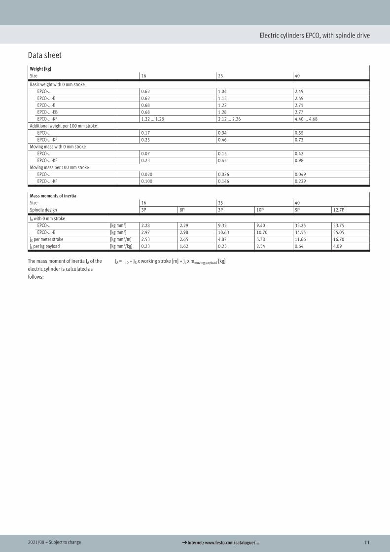
Weight [kg]Size 16 25 40
Basic weight with 0 mm strokeEPCO-... 0.62 1.04 2.49EPCO-...-E 0.62 1.13 2.59EPCO-...-B 0.68 1.22 2.71EPCO-...-EB 0.68 1.28 2.77EPCO-...-KF 1.22 ... 1.28 2.12 ... 2.36 4.40 ... 4.68
Additional weight per 100 mm strokeEPCO-... 0.17 0.34 0.55EPCO-...-KF 0.25 0.46 0.73
Moving mass with 0 mm strokeEPCO-... 0.07 0.15 0.42EPCO-...-KF 0.23 0.45 0.98
Moving mass per 100 mm strokeEPCO-... 0.020 0.026 0.049EPCO-...-KF 0.100 0.146 0.229
Mass moments of inertiaSize 16 25 40Spindle design 3P 8P 3P 10P 5P 12.7P
J0 with 0 mm strokeEPCO-... [kg mm2] 2.28 2.29 9.33 9.40 33.25 33.75EPCO-...-B [kg mm2] 2.97 2.98 10.63 10.70 34.55 35.05
jS per meter stroke [kg mm2/m] 2.53 2.65 4.87 5.78 11.66 16.70jL per kg payload [kg mm2/kg] 0.23 1.62 0.23 2.54 0.64 4.09
The mass moment of inertia JA of the electric cylinder is calculated as follows:
JA = J0 + jS x working stroke [m] + jL x mmoving payload [kg]

12 d Internet: www.festo.com/catalogue/... Subject to change – 2021/08
Electric cylinders EPCO, with spindle drive
Data sheet
MaterialsSectional view
1 65432
Electric cylinder
[1] Bearing cap Smooth-anodised wrought aluminium alloy[2] Cylinder barrel Smooth-anodised wrought aluminium alloy[3] Piston rod High-alloy stainless steel[4] Spindle Rolled steel[5] Spindle nut Steel[6] Drive cover Wrought aluminium alloy
Note on materials RoHS-compliantContains paint-wetting impairment substances
Piston rod deflection f as a function of projection A and transverse load F
EPCO-...
l [mm]
f[m
m]
0 100 200 300 400 500 6000
1
2
3
4
5
6
EPCO-16 (F = 2 N)EPCO-25 (F = 3 N)EPCO-40 (F = 6 N)
Materials
132021/08 – Subject to change d Internet: www.festo.com/catalogue/...
Electric cylinders EPCO, with spindle drive
Data sheet
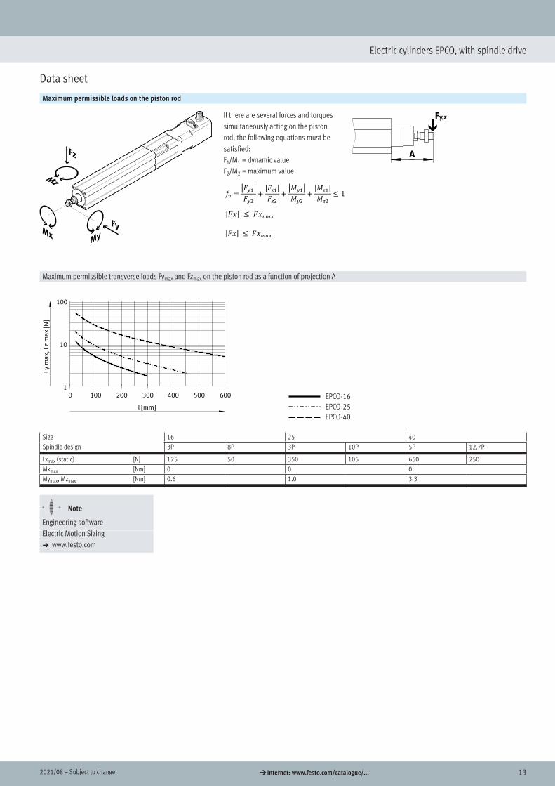
Maximum permissible loads on the piston rod
𝑓𝑓𝑓𝑓𝑣𝑣𝑣𝑣 =�𝐹𝐹𝐹𝐹𝑦𝑦𝑦𝑦1�𝐹𝐹𝐹𝐹𝑦𝑦𝑦𝑦2
+|𝐹𝐹𝐹𝐹𝑧𝑧𝑧𝑧1|𝐹𝐹𝐹𝐹𝑧𝑧𝑧𝑧2
+�𝑀𝑀𝑀𝑀𝑦𝑦𝑦𝑦1�𝑀𝑀𝑀𝑀𝑦𝑦𝑦𝑦2
+|𝑀𝑀𝑀𝑀𝑧𝑧𝑧𝑧1|𝑀𝑀𝑀𝑀𝑧𝑧𝑧𝑧2
≤ 1
If there are several forces and torques simultaneously acting on the piston rod, the following equations must be satisfied:F1/M1 = dynamic valueF2/M2 = maximum value
|𝐹𝐹𝐹𝐹𝐹𝐹𝐹𝐹| ≤ 𝐹𝐹𝐹𝐹𝐹𝐹𝐹𝐹𝑚𝑚𝑚𝑚𝑚𝑚𝑚𝑚𝑚𝑚𝑚𝑚 |𝐹𝐹𝐹𝐹𝐹𝐹𝐹𝐹| ≤ 𝐹𝐹𝐹𝐹𝐹𝐹𝐹𝐹𝑚𝑚𝑚𝑚𝑚𝑚𝑚𝑚𝑚𝑚𝑚𝑚
Maximum permissible transverse loads Fymax and Fzmax on the piston rod as a function of projection AEPCO-...
l [mm]
Fym
ax,
Fzm
ax
[N]
0 100 200 300 400 500 6001
10
100
EPCO-16EPCO-25EPCO-40
Size 16 25 40Spindle design 3P 8P 3P 10P 5P 12.7P
Fxmax (static) [N] 125 50 350 105 650 250Mxmax [Nm] 0 0 0Mymax, Mzmax [Nm] 0.6 1.0 3.3
H- - Note
Engineering softwareElectric Motion Sizinga www.festo.com
14 d Internet: www.festo.com/catalogue/... Subject to change – 2021/08
Electric cylinders EPCO, with spindle drive
Data sheet
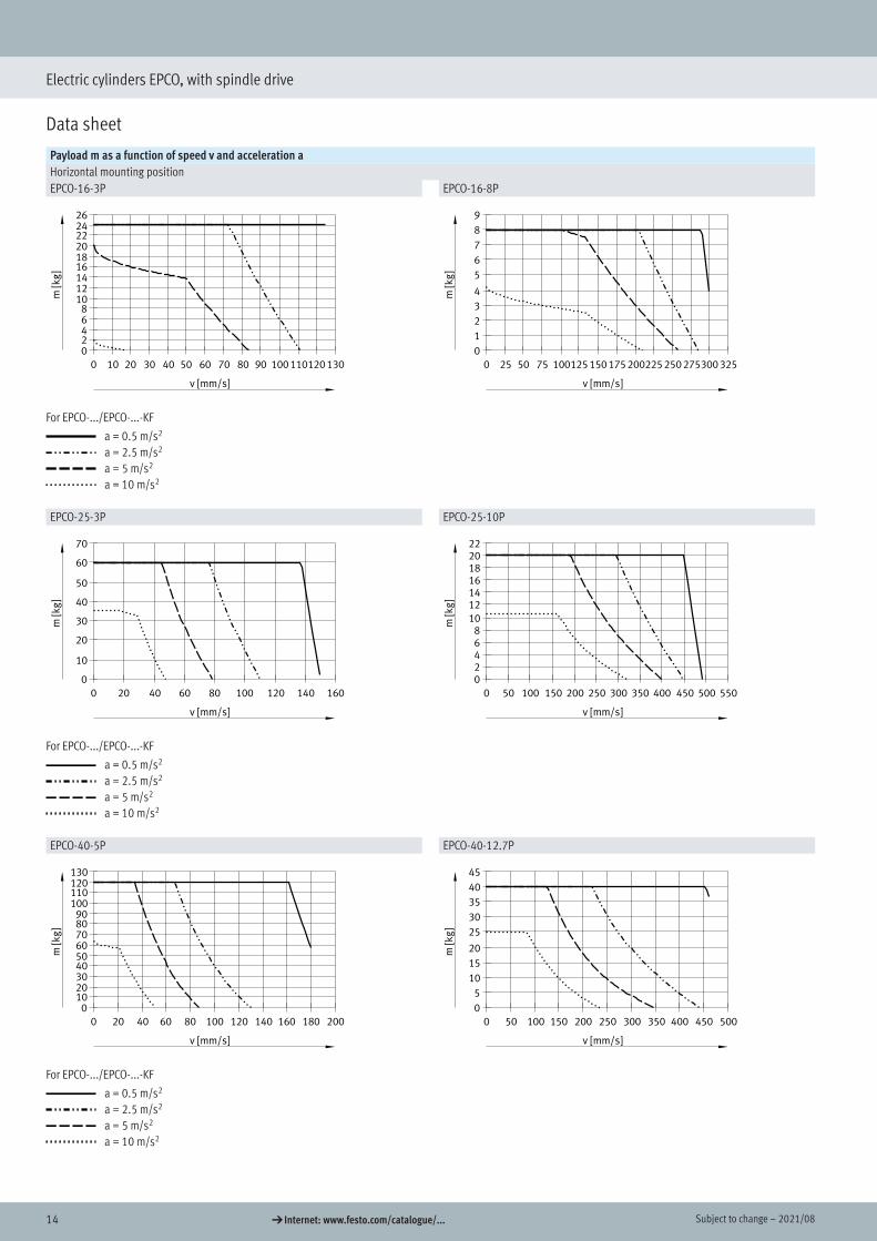
Payload m as a function of speed v and acceleration aHorizontal mounting positionEPCO-16-3P EPCO-16-8P
For EPCO-.../EPCO-...-KF
a = 0.5 m/s2
a = 2.5 m/s2
a = 5 m/s2
a = 10 m/s2
EPCO-25-3P EPCO-25-10P
For EPCO-.../EPCO-...-KF
a = 0.5 m/s2
a = 2.5 m/s2
a = 5 m/s2
a = 10 m/s2
EPCO-40-5P EPCO-40-12.7P
For EPCO-.../EPCO-...-KF
a = 0.5 m/s2
a = 2.5 m/s2
a = 5 m/s2
a = 10 m/s2
152021/08 – Subject to change d Internet: www.festo.com/catalogue/...
Electric cylinders EPCO, with spindle drive
Data sheet
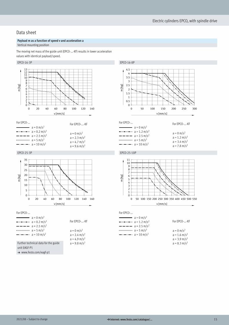
Payload m as a function of speed v and acceleration aVertical mounting position
The moving net mass of the guide unit (EPCO-...-KF) results in lower acceleration values with identical payload/speed.
EPCO-16-3P EPCO-16-8P
For EPCO-...
a = 0 m/s2
a = 0.2 m/s2
a = 2.5 m/s2
a = 5 m/s2
a = 10 m/s2
For EPCO-...
a = 0 m/s2
a = 1.2 m/s2
a = 2.5 m/s2
a = 5 m/s2
a = 10 m/s2
EPCO-25-3P EPCO-25-10P
For EPCO-...
a = 0 m/s2
a = 0.2 m/s2
a = 2.5 m/s2
a = 5 m/s2
a = 10 m/s2
For EPCO-...
a = 0 m/s2
a = 1.2 m/s2
a = 2.5 m/s2
a = 5 m/s2
a = 10 m/s2
Further technical data for the guide unit EAGF-P1 a www.festo.com/eagf-p1
For EPCO-...-KF
a = 0 m/s2
a = 2.3 m/s2
a = 4.7 m/s2
a = 9.6 m/s2
For EPCO-...-KF
a = 0 m/s2
a = 1.2 m/s2
a = 3.4 m/s2
a = 7.8 m/s2
For EPCO-...-KF
a = 0 m/s2
a = 2.4 m/s2
a = 4.9 m/s2
a = 9.8 m/s2
For EPCO-...-KF
a = 0 m/s2
a = 1.6 m/s2
a = 3.9 m/s2
a = 8.3 m/s2
16 d Internet: www.festo.com/catalogue/... Subject to change – 2021/08
Electric cylinders EPCO, with spindle drive
Data sheet
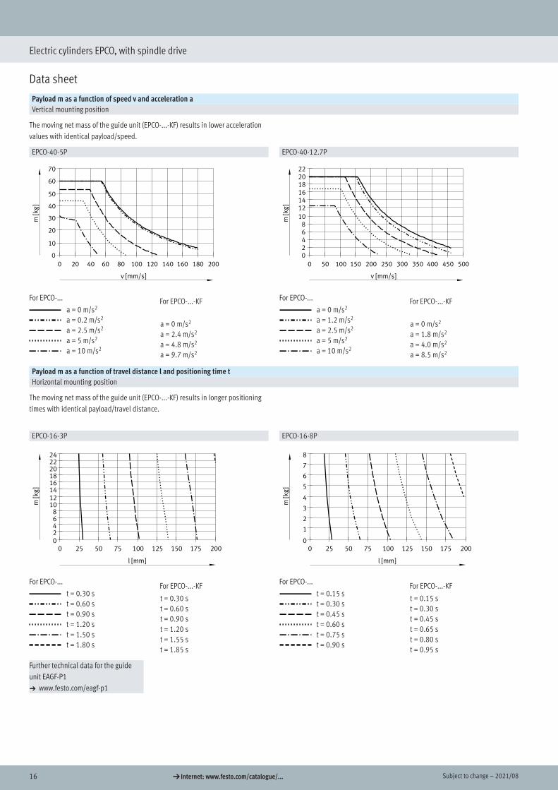
Payload m as a function of speed v and acceleration aVertical mounting position
The moving net mass of the guide unit (EPCO-...-KF) results in lower acceleration values with identical payload/speed.
EPCO-40-5P EPCO-40-12.7P
For EPCO-...
a = 0 m/s2
a = 0.2 m/s2
a = 2.5 m/s2
a = 5 m/s2
a = 10 m/s2
For EPCO-...
a = 0 m/s2
a = 1.2 m/s2
a = 2.5 m/s2
a = 5 m/s2
a = 10 m/s2
Payload m as a function of travel distance l and positioning time tHorizontal mounting position
The moving net mass of the guide unit (EPCO-...-KF) results in longer positioning times with identical payload/travel distance.
EPCO-16-3P EPCO-16-8PEPCO-16-3P (horizontal)
l [mm]
m[k
g]
0 25 50 75 100 125 150 175 20002468
1012141618202224
EPCO-16-8P (horizontal)
l [mm]
m[k
g]
0 25 50 75 100 125 150 175 2000
1
2
3
4
5
6
7
8
For EPCO-...
t = 0.30 st = 0.60 st = 0.90 st = 1.20 st = 1.50 st = 1.80 s
For EPCO-...
t = 0.15 st = 0.30 st = 0.45 st = 0.60 st = 0.75 st = 0.90 s
Further technical data for the guide unit EAGF-P1 a www.festo.com/eagf-p1
For EPCO-...-KF
a = 0 m/s2
a = 2.4 m/s2
a = 4.8 m/s2
a = 9.7 m/s2
For EPCO-...-KF
a = 0 m/s2
a = 1.8 m/s2
a = 4.0 m/s2
a = 8.5 m/s2
For EPCO-...-KF
t = 0.30 st = 0.60 st = 0.90 st = 1.20 st = 1.55 st = 1.85 s
For EPCO-...-KF
t = 0.15 st = 0.30 st = 0.45 st = 0.65 st = 0.80 st = 0.95 s
172021/08 – Subject to change d Internet: www.festo.com/catalogue/...
Electric cylinders EPCO, with spindle drive
Data sheet
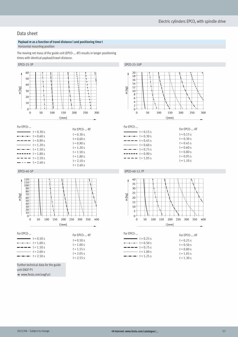
Payload m as a function of travel distance l and positioning time tHorizontal mounting position
The moving net mass of the guide unit (EPCO-...-KF) results in longer positioning times with identical payload/travel distance.
EPCO-25-3P EPCO-25-10PEPCO-25-3P (horizontal)
l [mm]
m[k
g]
0 50 100 150 200 250 3000
10
20
30
40
50
60
EPCO-25-10P (horizontal)
l [mm]
m[k
g]
0 50 100 150 200 250 3000
2
4
6
810
12
14
16
1820
For EPCO-...
t = 0.30 st = 0.60 st = 0.90 st = 1.20 st = 1.50 st = 1.80 st = 2.10 st = 2.40 s
For EPCO-...
t = 0.15 st = 0.30 st = 0.45 st = 0.60 st = 0.75 st = 0.90 st = 1.05 s
EPCO-40-5P EPCO-40-12.7PEPCO-40-5P (horizontal)
l [mm]
m[k
g]
0 50 100 150 200 250 300 350 4000
102030405060708090
100110120
EPCO-40-12.7P (horizontal)
l [mm]
m[k
g]
0 50 100 150 200 250 300 350 4000
5
10
15
20
25
30
35
40
For EPCO-...
t = 0.50 st = 1.00 st = 1.50 st = 2.00 st = 2.50 s
For EPCO-...
t = 0.25 st = 0.50 st = 0.75 st = 1.00 st = 1.25 s
Further technical data for the guide unit EAGF-P1 a www.festo.com/eagf-p1
For EPCO-...-KF
t = 0.30 st = 0.60 st = 0.90 st = 1.20 st = 1.50 st = 1.80 st = 2.10 st = 2.40 s
For EPCO-...-KF
t = 0.15 st = 0.30 st = 0.45 st = 0.60 st = 0.80 st = 0.95 st = 1.10 s
For EPCO-...-KF
t = 0.50 st = 1.00 st = 1.55 st = 2.05 st = 2.55 s
For EPCO-...-KF
t = 0.25 st = 0.50 st = 0.80 st = 1.05 st = 1.30 s
18 d Internet: www.festo.com/catalogue/... Subject to change – 2021/08
Electric cylinders EPCO, with spindle drive
Data sheet
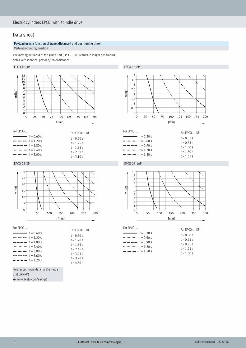
Payload m as a function of travel distance l and positioning time tVertical mounting position
The moving net mass of the guide unit (EPCO-...-KF) results in longer positioning times with identical payload/travel distance.
EPCO-16-3P EPCO-16-8PEPCO-16-8P (vertikal)
l [mm]m
[kg
]
0 25 50 75 100 125 150 175 2000
0.5
1
1.5
2
2.5
3
3.5
4
For EPCO-...
t = 0.60 st = 1.20 st = 1.80 st = 2.40 st = 3.00 s
For EPCO-...
t = 0.30 st = 0.60 st = 0.90 st = 1.20 st = 1.50 s
EPCO-25-3P EPCO-25-10PEPCO-25-3P (vertikal)
l [mm]
m[k
g]
0 50 100 150 200 250 3000
5
10
15
20
25
30
EPCO-25-10P (vertikal)
l [mm]
m[k
g]
0 50 100 150 200 250 3000
1
2
3
45
6
7
8
910
For EPCO-...
t = 0.60 st = 1.20 st = 1.80 st = 2.40 st = 3.00 st = 3.60 st = 4.20 s
For EPCO-...
t = 0.30 st = 0.60 st = 0.90 st = 1.20 st = 1.50 s
Further technical data for the guide unit EAGF-P1 a www.festo.com/eagf-p1
For EPCO-...-KF
t = 0.60 st = 1.25 st = 1.85 st = 2.50 st = 3.10 s
For EPCO-...-KF
t = 0.35 st = 0.65 st = 1.00 st = 1.30 st = 1.65 s
For EPCO-...-KF
t = 0.60 st = 1.20 st = 1.85 st = 2.45 st = 3.05 st = 3.70 st = 4.30 s
For EPCO-...-KF
t = 0.30 st = 0.65 st = 0.95 st = 1.25 st = 1.60 s
192021/08 – Subject to change d Internet: www.festo.com/catalogue/...
Electric cylinders EPCO, with spindle drive
Data sheet
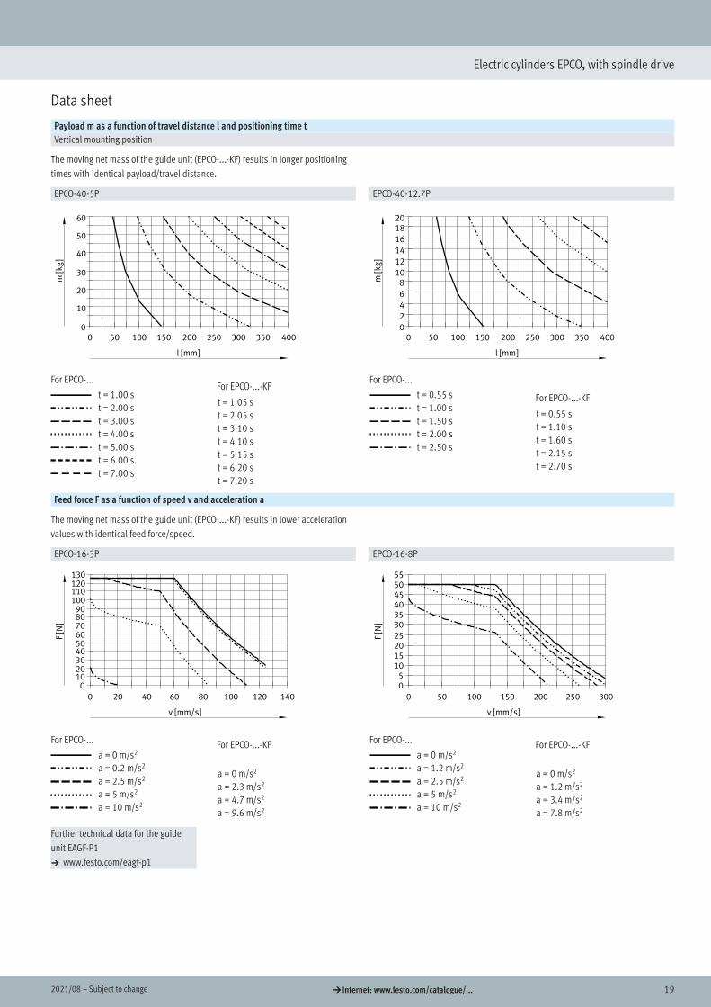
Payload m as a function of travel distance l and positioning time tVertical mounting position
The moving net mass of the guide unit (EPCO-...-KF) results in longer positioning times with identical payload/travel distance.
EPCO-40-5P EPCO-40-12.7PEPCO-40-5P (vertikal)
l [mm]
m[k
g]
0 50 100 150 200 250 300 350 4000
10
20
30
40
50
60
EPCO-40-12.7P (vertikal)
l [mm]
m[k
g]
0 50 100 150 200 250 300 350 4000
2
4
6
810
12
14
16
1820
For EPCO-...
t = 1.00 st = 2.00 st = 3.00 st = 4.00 st = 5.00 st = 6.00 st = 7.00 s
For EPCO-...
t = 0.55 st = 1.00 st = 1.50 st = 2.00 st = 2.50 s
Feed force F as a function of speed v and acceleration a
The moving net mass of the guide unit (EPCO-...-KF) results in lower acceleration values with identical feed force/speed.
EPCO-16-3P EPCO-16-8P
For EPCO-...
a = 0 m/s2
a = 0.2 m/s2
a = 2.5 m/s2
a = 5 m/s2
a = 10 m/s2
For EPCO-...
a = 0 m/s2
a = 1.2 m/s2
a = 2.5 m/s2
a = 5 m/s2
a = 10 m/s2
Further technical data for the guide unit EAGF-P1 a www.festo.com/eagf-p1
For EPCO-...-KF
t = 1.05 st = 2.05 st = 3.10 st = 4.10 st = 5.15 st = 6.20 st = 7.20 s
For EPCO-...-KF
a = 0 m/s2
a = 2.3 m/s2
a = 4.7 m/s2
a = 9.6 m/s2
For EPCO-...-KF
a = 0 m/s2
a = 1.2 m/s2
a = 3.4 m/s2
a = 7.8 m/s2
For EPCO-...-KF
t = 0.55 st = 1.10 st = 1.60 st = 2.15 st = 2.70 s
20 d Internet: www.festo.com/catalogue/... Subject to change – 2021/08
Electric cylinders EPCO, with spindle drive
Data sheet
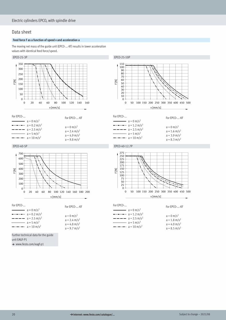
Feed force F as a function of speed v and acceleration a
The moving net mass of the guide unit (EPCO-...-KF) results in lower acceleration values with identical feed force/speed.
EPCO-25-3P EPCO-25-10P
For EPCO-...
a = 0 m/s2
a = 0.2 m/s2
a = 2.5 m/s2
a = 5 m/s2
a = 10 m/s2
For EPCO-...
a = 0 m/s2
a = 1.2 m/s2
a = 2.5 m/s2
a = 5 m/s2
a = 10 m/s2
EPCO-40-5P EPCO-40-12.7PEPCO-40-5P
v [mm/s]
F[N
]
0 20 40 60 80 100 120 140 160 180 2000
100
200
300
400
500
600
700
For EPCO-...
a = 0 m/s2
a = 0.2 m/s2
a = 2.5 m/s2
a = 5 m/s2
a = 10 m/s2
For EPCO-...
a = 0 m/s2
a = 1.2 m/s2
a = 2.5 m/s2
a = 5 m/s2
a = 10 m/s2
Further technical data for the guide unit EAGF-P1 a www.festo.com/eagf-p1
For EPCO-...-KF
a = 0 m/s2
a = 2.4 m/s2
a = 4.9 m/s2
a = 9.8 m/s2
For EPCO-...-KF
a = 0 m/s2
a = 1.6 m/s2
a = 3.9 m/s2
a = 8.3 m/s2
For EPCO-...-KF
a = 0 m/s2
a = 2.4 m/s2
a = 4.8 m/s2
a = 9.7 m/s2
For EPCO-...-KF
a = 0 m/s2
a = 1.8 m/s2
a = 4.0 m/s2
a = 8.5 m/s2

212021/08 – Subject to change d Internet: www.festo.com/catalogue/...
Electric cylinders EPCO, with spindle drive
Data sheet
Calculating the mean feed force Fxm with the electric cylinder EPCO
The peak feed force value must not exceed the maximum feed force within a movement cycle. The peak value is generally achieved in vertical operation during the acceleration phase of the upwards stroke. If the maximum feed force is exceeded, this can increase wear and thus shorten the service life of the ball screw. The maximum speed must likewise not be exceed-ed:
Fx š Fxmax.
andvx š vxmax.
Mean feed force (to DIN 69051-4)
During operation, the continuous feed force may be briefly exceeded up to the maximum feed force. The continuous feed force must, however, be adhered to when averaged over a movement cycle:
Fxm š Fxcontinuous
Fx [N]
q [100%]
Fxmax
Fxm Fx3
Fx2
Fx1
q1 q2 q3
Mean feed speed (to DIN 69051-4)
vx [mm/s]
q [100%]
vxmax
vxm vx3
vx2
vx1
q1 q2 q3
Fx Feed forceFxm Mean feed forceFxmax. Max. feed forceFxcontinuous Continuous feed force
vx Feed speedvxm Mean feed speedvx Max. feed speed
𝐹𝐹𝐹𝐹𝑥𝑥𝑥𝑥𝑥𝑥𝑥𝑥=��𝐹𝐹𝐹𝐹𝑥𝑥𝑥𝑥3 ∙𝑣𝑣𝑣𝑣𝑥𝑥𝑥𝑥𝑣𝑣𝑣𝑣𝑥𝑥𝑥𝑥𝑥𝑥𝑥𝑥
∙𝑞𝑞𝑞𝑞
1003
=
𝐹𝐹𝐹𝐹𝑥𝑥𝑥𝑥𝑥𝑥𝑥𝑥=�𝐹𝐹𝐹𝐹𝑥𝑥𝑥𝑥13 ∙
𝑣𝑣𝑣𝑣𝑥𝑥𝑥𝑥1𝑣𝑣𝑣𝑣𝑥𝑥𝑥𝑥𝑥𝑥𝑥𝑥
∙𝑞𝑞𝑞𝑞1
100+ 𝐹𝐹𝐹𝐹𝑥𝑥𝑥𝑥23 ∙
𝑣𝑣𝑣𝑣𝑥𝑥𝑥𝑥2𝑣𝑣𝑣𝑣𝑥𝑥𝑥𝑥𝑥𝑥𝑥𝑥
∙𝑞𝑞𝑞𝑞2
100+ 𝐹𝐹𝐹𝐹𝑥𝑥𝑥𝑥33 ∙
𝑣𝑣𝑣𝑣𝑥𝑥𝑥𝑥3𝑣𝑣𝑣𝑣𝑥𝑥𝑥𝑥𝑥𝑥𝑥𝑥
∙𝑞𝑞𝑞𝑞3
1003
+⋯
𝑣𝑣𝑣𝑣𝑥𝑥𝑥𝑥𝑥𝑥𝑥𝑥 = �𝑣𝑣𝑣𝑣𝑥𝑥𝑥𝑥 ∙𝑞𝑞𝑞𝑞
100= 𝑣𝑣𝑣𝑣𝑥𝑥𝑥𝑥1 ∙
𝑞𝑞𝑞𝑞1100
+ 𝑣𝑣𝑣𝑣𝑥𝑥𝑥𝑥2 ∙𝑞𝑞𝑞𝑞2
100+ 𝑣𝑣𝑣𝑣𝑥𝑥𝑥𝑥3 ∙
𝑞𝑞𝑞𝑞3100
+⋯
22 d Internet: www.festo.com/catalogue/... Subject to change – 2021/08
Electric cylinders EPCO, with spindle drive
Data sheet
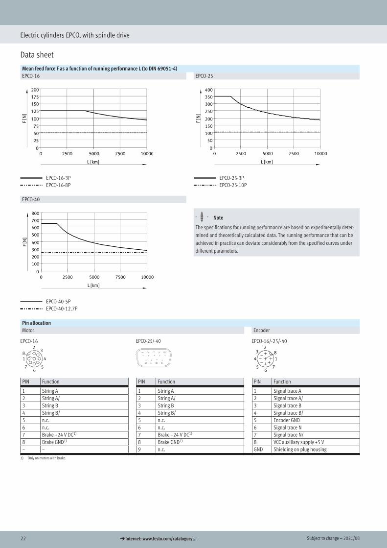
Mean feed force F as a function of running performance L (to DIN 69051-4)EPCO-16 EPCO-25
EPCO-16-3PEPCO-16-8P
EPCO-25
L [km]
F[N
]
0 2500 5000 7500 100000
50
100
150
200
250
300
350
400
EPCO-25-3PEPCO-25-10P
EPCO-40EPCO-40
L [km]
F[N
]
0 2500 5000 7500 100000
100
200
300
400
500
600
700
800
EPCO-40-5PEPCO-40-12.7P
H- - Note
The specifications for running performance are based on experimentally deter-mined and theoretically calculated data. The running performance that can be achieved in practice can deviate considerably from the specified curves under different parameters.
Pin allocationMotor Encoder
EPCO-16 EPCO-25/-40 EPCO-16/-25/-40
PIN Function PIN Function PIN Function
1 String A 1 String A 1 Signal trace A2 String A/ 2 String A/ 2 Signal trace A/3 String B 3 String B 3 Signal trace B4 String B/ 4 String B/ 4 Signal trace B/5 n.c. 5 n.c. 5 Encoder GND6 n.c. 6 n.c. 6 Signal trace N7 Brake +24 V DC1) 7 Brake +24 V DC1) 7 Signal trace N/8 Brake GND1) 8 Brake GND1) 8 VCC auxiliary supply +5 V– – 9 n.c. GND Shielding on plug housing
1) Only on motors with brake.
232021/08 – Subject to change d Internet: www.festo.com/catalogue/...
Electric cylinders EPCO, with spindle drive
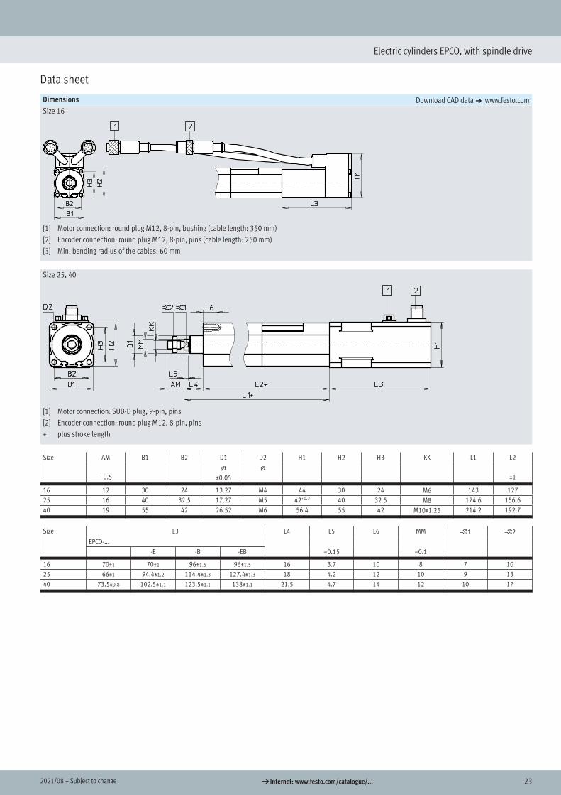
Data sheet
Dimensions Download CAD data a www.festo.comSize 16
[1] Motor connection: round plug M12, 8-pin, bushing (cable length: 350 mm)[2] Encoder connection: round plug M12, 8-pin, pins (cable length: 250 mm)[3] Min. bending radius of the cables: 60 mm
Size 25, 40
[1] Motor connection: SUB-D plug, 9-pin, pins[2] Encoder connection: round plug M12, 8-pin, pins+ plus stroke length
Size AM B1 B2 D1 D2 H1 H2 H3 KK L1 L2
–0.5@
±0.05@
±1
16 12 30 24 13.27 M4 44 30 24 M6 143 12725 16 40 32.5 17.27 M5 42+0.3 40 32.5 M8 174.6 156.640 19 55 42 26.52 M6 56.4 55 42 M10x1.25 214.2 192.7
Size L3 L4 L5 L6 MM ß1 ß2EPCO-...
-E -B -EB –0.15 –0.1
16 70±1 70±1 96±1.5 96±1.5 16 3.7 10 8 7 1025 66±1 94.4±1.2 114.4±1.3 127.4±1.3 18 4.2 12 10 9 1340 73.5±0.8 102.5±1.1 123.5±1.1 138±1.1 21.5 4.7 14 12 10 17
Dimensions
24 d Internet: www.festo.com/catalogue/... Subject to change – 2021/08
Electric cylinders EPCO, with spindle drive
Data sheet
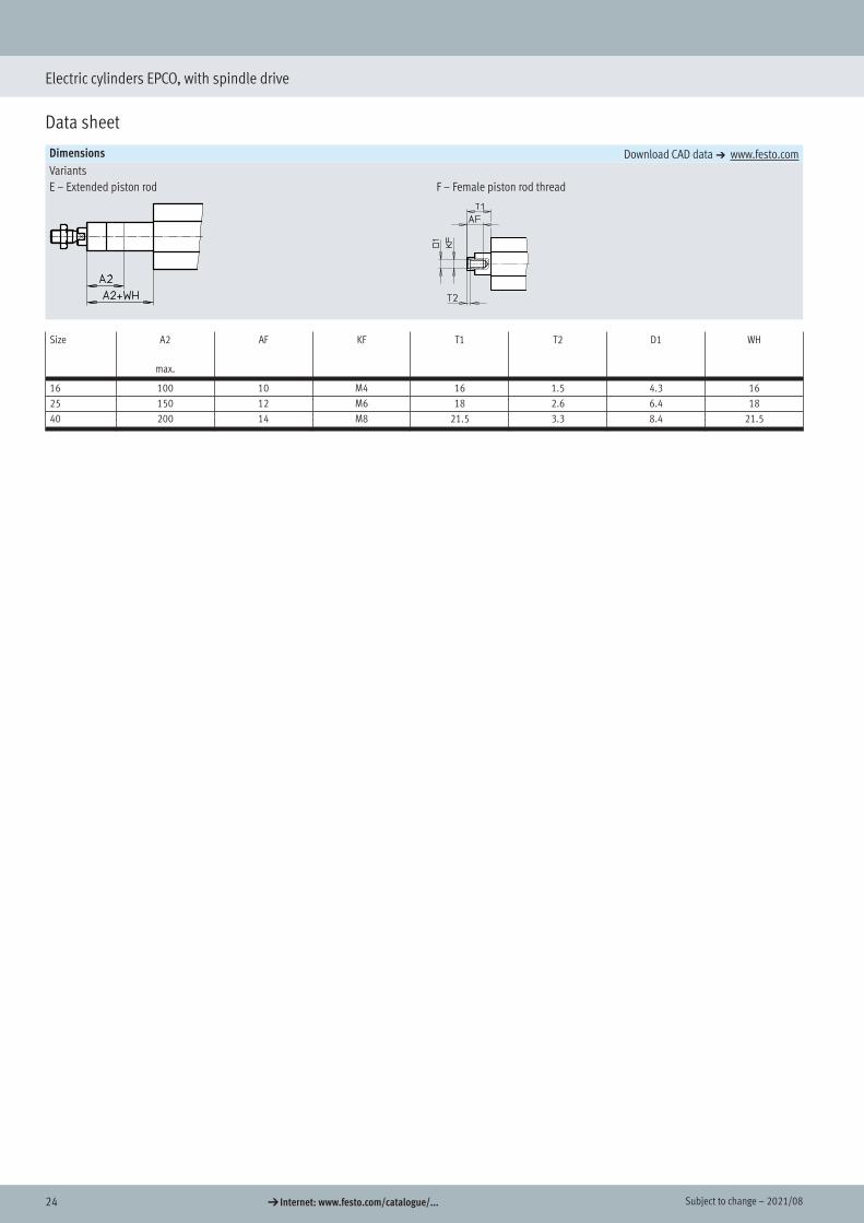
Dimensions Download CAD data a www.festo.comVariantsE – Extended piston rod F – Female piston rod thread
Size A2
max.
AF KF T1 T2 D1 WH
16 100 10 M4 16 1.5 4.3 1625 150 12 M6 18 2.6 6.4 1840 200 14 M8 21.5 3.3 8.4 21.5

252021/08 – Subject to change d Internet: www.festo.com/catalogue/...
Electric cylinders EPCO, with spindle drive
Data sheet
Ordering data – EPCO-16Stroke[mm]
Part no. Type Stroke[mm]
Part no. Type
Spindle pitch 3 mm/rev, with encoder Spindle pitch 8 mm/rev, with encoder50 1476415 EPCO-16-50-3P-ST-E 50 1476522 EPCO-16-50-8P-ST-E100 1476417 EPCO-16-100-3P-ST-E 100 1476524 EPCO-16-100-8P-ST-E150 1476419 EPCO-16-150-3P-ST-E 150 1476526 EPCO-16-150-8P-ST-E200 1476421 EPCO-16-200-3P-ST-E 200 1476528 EPCO-16-200-8P-ST-E
Ordering data – EPCO-25Stroke[mm]
Part no. Type Stroke[mm]
Part no. Type
Spindle pitch 3 mm/rev, with encoder Spindle pitch 10 mm/rev, with encoder50 1470698 EPCO-25-50-3P-ST-E 50 1470769 EPCO-25-50-10P-ST-E100 1470700 EPCO-25-100-3P-ST-E 100 1470771 EPCO-25-100-10P-ST-E150 1470702 EPCO-25-150-3P-ST-E 150 1470773 EPCO-25-150-10P-ST-E200 1470704 EPCO-25-200-3P-ST-E 200 1470775 EPCO-25-200-10P-ST-E300 1470706 EPCO-25-300-3P-ST-E 300 1470777 EPCO-25-300-10P-ST-E
Ordering data – EPCO-40Stroke[mm]
Part no. Type Stroke[mm]
Part no. Type
Spindle pitch 5 mm/rev, with encoder Spindle pitch 12.7 mm/rev, with encoder50 1472501 EPCO-40-50-5P-ST-E 50 1472617 EPCO-40-50-12.7P-ST-E100 1472503 EPCO-40-100-5P-ST-E 100 1472619 EPCO-40-100-12.7P-ST-E150 1472505 EPCO-40-150-5P-ST-E 150 1472621 EPCO-40-150-12.7P-ST-E200 1472507 EPCO-40-200-5P-ST-E 200 1472623 EPCO-40-200-12.7P-ST-E300 1472509 EPCO-40-300-5P-ST-E 300 1472625 EPCO-40-300-12.7P-ST-E
H- - Note
Variants ordered via modular product system a page 26
H- - Note
Position sensing is only possible in combination with characteristic "A" a page 26 (modular product system)
Ordering data
26 d Internet: www.festo.com/catalogue/... Subject to change – 2021/08
Electric cylinders EPCO, with spindle drive
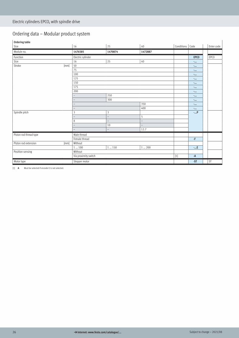
Ordering data – Modular product system
Ordering tableSize 16 25 40 Conditions Code Enter code
Module no. 1476585 1470874 1472887
Function Electric cylinder EPCO EPCOSize 16 25 40 -...Stroke [mm] 50 -...
75 -...100 -...125 -...150 -...175 -...200 -...– 250 -...– 300 -...– 350 -...– 400 -...
Spindle pitch 3 3 -...P– – 58 – –– 10 –– – 12.7
Piston rod thread type Male threadFemale thread -F
Piston rod extension [mm] Without1 ... 100 1 ... 150 1 ... 200 -...E
Position sensing WithoutVia proximity switch [1] -A
Motor type Stepper motor -ST ST
[1] A Must be selected if encoder E is not selected.
Ordering data – Modular product system
272021/08 – Subject to change d Internet: www.festo.com/catalogue/...
Electric cylinders EPCO, with spindle drive
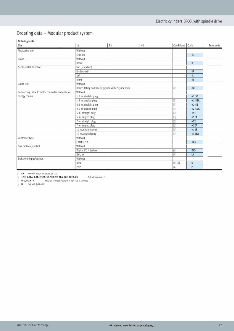
Ordering data – Modular product system
Ordering tableSize 16 25 40 Conditions Code Enter code
Measuring unit WithoutEncoder -E
Brake WithoutBrake B
Cable outlet direction Top (standard)Underneath -DLeft -LRight -R
Guide unit WithoutRecirculating ball bearing guide with 2 guide rods [2] -KF
Connecting cable to motor controller, suitable for energy chains
Without1.5 m, straight plug +1.5E1.5 m, angled plug [3] +1.5EA2.5 m, straight plug [3] +2.5E2.5 m, angled plug [3] +2.5EA5 m, straight plug [3] +5E5 m, angled plug [3] +5EA7 m, straight plug [3] +7E7 m, angled plug [3] +7EA10 m, straight plug [3] +10E10 m, angled plug [3] +10EA
Controller type WithoutCMMO, 5 A +C5
Bus protocol/control WithoutDigital I/O interface [4] DIOIO-Link [4] LK
Switching input/output WithoutNPN [4] [5] NPNP [4] P
[2] KF Not with piston rod extension ...E
[3] 1.5E, 1.5EA, 2.5E, 2.5EA, 5E, 5EA, 7E, 7EA, 10E, 10EA, C5 Only with encoder E
[4] DIO, LK, N, P Must be selected if controller type +C5 is selected
[5] N Not with IO-Link LK
28 d Internet: www.festo.com/catalogue/... Subject to change – 2021/08
Electric cylinders EPCO, with spindle drive
Accessories
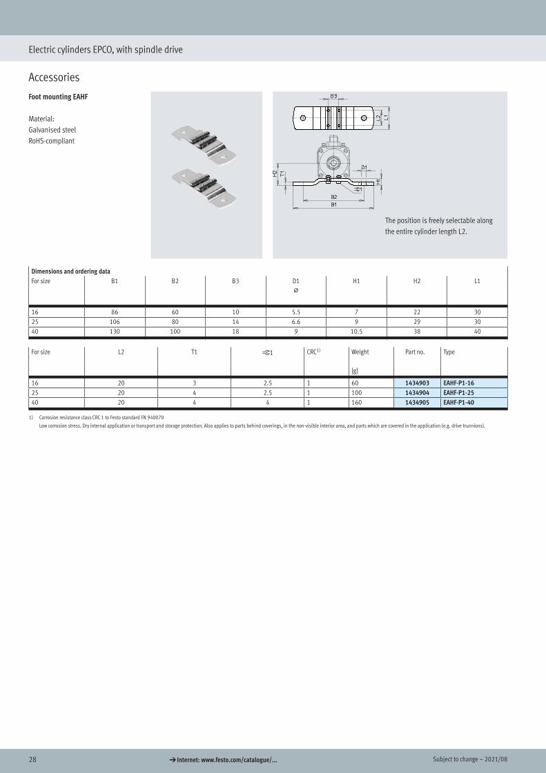
Foot mounting EAHF
Material:Galvanised steelRoHS-compliant
The position is freely selectable along the entire cylinder length L2.
Dimensions and ordering dataFor size B1 B2 B3 D1
@H1 H2 L1
16 86 60 10 5.5 7 22 3025 106 80 14 6.6 9 29 3040 130 100 18 9 10.5 38 40
For size L2 T1 ß1 CRC1) Weight Part no. Type
[g]
16 20 3 2.5 1 60 1434903 EAHF-P1-1625 20 4 2.5 1 100 1434904 EAHF-P1-2540 20 4 4 1 160 1434905 EAHF-P1-40
1) Corrosion resistance class CRC 1 to Festo standard FN 940070
Low corrosion stress. Dry internal application or transport and storage protection. Also applies to parts behind coverings, in the non-visible interior area, and parts which are covered in the application (e.g. drive trunnions).
Accessories
Foot mounting

292021/08 – Subject to change d Internet: www.festo.com/catalogue/...
Electric cylinders EPCO, with spindle drive
Accessories
Flange mounting EAHH
Material:Galvanised steelRoHS-compliant
The position is freely selectable along the entire cylinder length L2.
Dimensions and ordering dataFor size B1 B2 B3 B4 D1
@H1 H2 H3 L1
16 77.2 60 10 45 5.5 38.3 34.6 20 4325 102 80 14 59 6.6 52.3 50.6 32 4440 119 100 18 76 9 64.5 56 36 54
For size L2 L3 T1 ß1 CRC1) Weight Part no. Type
[g]
16 20 30 3 2.5 1 80 1434906 EAHH-P1-1625 20 30 4 2.5 1 150 1434907 EAHH-P1-2540 20 40 4 4 1 240 1434908 EAHH-P1-40
1) Corrosion resistance class CRC 1 to Festo standard FN 940070
Low corrosion stress. Dry internal application or transport and storage protection. Also applies to parts behind coverings, in the non-visible interior area, and parts which are covered in the application (e.g. drive trunnions).
Flange mounting

30 d Internet: www.festo.com/catalogue/... Subject to change – 2021/08
Electric cylinders EPCO, with spindle drive
Accessories
Swivel mounting EAHS
Material:Galvanised steelRoHS-compliant
The position is freely selectable along the entire cylinder length L2.
Dimensions and ordering dataFor size B1 B2 B3 B4 D1
@H1 H2
e9
16 71 60 10 45 8 33 2125 95 80 14 59 12 37.5 2740 118 100 18 76 16 55 36.5
For size L1 L2 T1 ß1 CRC1) Weight Part no. Type
[g]
16 30 20 3 2.5 1 80 1434909 EAHS-P1-1625 30 20 4 2.5 1 140 1434910 EAHS-P1-2540 40 20 4 4 1 260 1434911 EAHS-P1-40
1) Corrosion resistance class CRC 1 to Festo standard FN 940070
Low corrosion stress. Dry internal application or transport and storage protection. Also applies to parts behind coverings, in the non-visible interior area, and parts which are covered in the application (e.g. drive trunnions).
Swivel mounting

312021/08 – Subject to change d Internet: www.festo.com/catalogue/...
Electric cylinders EPCO, with spindle drive
Accessories
Adapter kit EAHA Material:Galvanised steel
RoHS-compliant
Dimensions and ordering dataFor size B1 B2 B3 D1 H1 H2 H3 H4
16 45 18 10 M4 35.9 29.8 18 1525 59 26 14 M5 49 44 26 2040 76 38 18 M6 66.9 60.8 38 27.5
For size L1 L2 L3 T1 ß1 CRC1) Weight Part no. Type
[g]
16 139 20 30 3 2.5 1 210 1434900 EAHA-P1-1625 174 20 30 4 2.5 1 480 1434901 EAHA-P1-2540 193.4 20 40 4 4 1 770 1434902 EAHA-P1-40
1) Corrosion resistance class CRC 1 to Festo standard FN 940070
Low corrosion stress. Dry internal application or transport and storage protection. Also applies to parts behind coverings, in the non-visible interior area, and parts which are covered in the application (e.g. drive trunnions).
Adapter kit
32 d Internet: www.festo.com/catalogue/... Subject to change – 2021/08
Electric cylinders EPCO, with spindle drive
Accessories
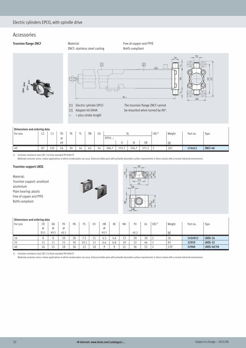
Trunnion flange ZNCF Material:ZNCF: stainless steel casting
Free of copper and PTFERoHS-compliant
[1] Electric cylinder EPCO[2] Adapter kit EAHA+ = plus stroke length
The trunnion flange ZNCF cannotbe mounted when turned by 90°.
Dimensions and ordering dataFor size C2 C3 TD TK TL TM US XL CRC1) Weight Part no. Type
@ EPCO-...
e9 -E -B -EB [g]
40 87 105 16 20 16 63 54 306.7 335.7 356.7 371.2 2 285 174412 ZNCF-40
1) Corrosion resistance class CRC 2 to Festo standard FN 940070
Moderate corrosion stress. Indoor applications in which condensation can occur. External visible parts with primarily decorative surface requirements in direct contact with a normal industrial environment.
Trunnion support LNZG
Material:Trunnion support: anodised aluminiumPlain bearing: plasticFree of copper and PTFERoHS-compliant
Dimensions and ordering dataFor size CR
@DA@
FK@
FN FS H1 HB@
KE NH TH UL CRC1) Weight Part no. Type
D11 H13 ±0.1 H13 ±0.2 [g]
16 8 8 10 20 7.5 11 4.5 4.6 13 20 30 2 26 1434912 LNZG-1625 12 11 15 30 10.5 15 6.6 6.8 18 32 46 2 83 32959 LNZG-3240 16 15 18 36 12 18 9 9 21 36 55 2 129 32960 LNZG-40/50
1) Corrosion resistance class CRC 2 to Festo standard FN 940070
Moderate corrosion stress. Indoor applications in which condensation can occur. External visible parts with primarily decorative surface requirements in direct contact with a normal industrial environment.
Trunnion flange
Trunnion support

332021/08 – Subject to change d Internet: www.festo.com/catalogue/...
Electric cylinders EPCO, with spindle drive
Accessories
Swivel flange SNCS Material:Die-cast aluminium
Free of copper and PTFERoHS-compliant
[1] Electric cylinder EPCO[2] Adapter kit EAHA+ = plus stroke length
Dimensions and ordering dataFor size CN
@E EP EX FL LT MS RA TG
+0.2 ±0.2 +1
40 12+0.015 54–0.5 12 16 25 16 17+0.5 17.5 38
For size XC CRC1) Weight Part no. TypeEPCO-...
-E -B -EB [g]
40 321.7 350.7 371.7 386.2 1 122 174398 SNCS-40
1) Corrosion resistance class CRC 1 to Festo standard FN 940070
Low corrosion stress. Dry internal application or transport and storage protection. Also applies to parts behind coverings, in the non-visible interior area, and parts which are covered in the application (e.g. drive trunnions).
Swivel flange SNCL Material:Wrought aluminium alloy
Free of copper and PTFERoHS-compliant
[1] Electric cylinder EPCO[2] Adapter kit EAHA+ = plus stroke length
Dimensions and ordering dataFor size CD EW FL L MR XC CRC1) Weight Part no. Type
@ EPCO-...
H9 h12 ±0.2 –0.5 -E -B -EB [g]
16 6 12 16 10 6 237 237 263 263 2 21 537791 SNCL-1625 8 16 20 14 8 269.6 298 318 331 2 41 537793 SNCL-2540 12 28 25 16 12 321.7 350.7 371.7 386.2 1 95 174405 SNCL-40
1) Corrosion resistance class CRC 1 to Festo standard FN 940070
Low corrosion stress. Dry internal application or transport and storage protection. Also applies to parts behind coverings, in the non-visible interior area, and parts which are covered in the application (e.g. drive trunnions).
Corrosion resistance class CRC 2 to Festo standard FN 940070
Moderate corrosion stress. Indoor applications in which condensation can occur. External visible parts with primarily decorative surface requirements in direct contact with a normal industrial environment.
Swivel flange
34 d Internet: www.festo.com/catalogue/... Subject to change – 2021/08
Electric cylinders EPCO, with spindle drive
Accessories
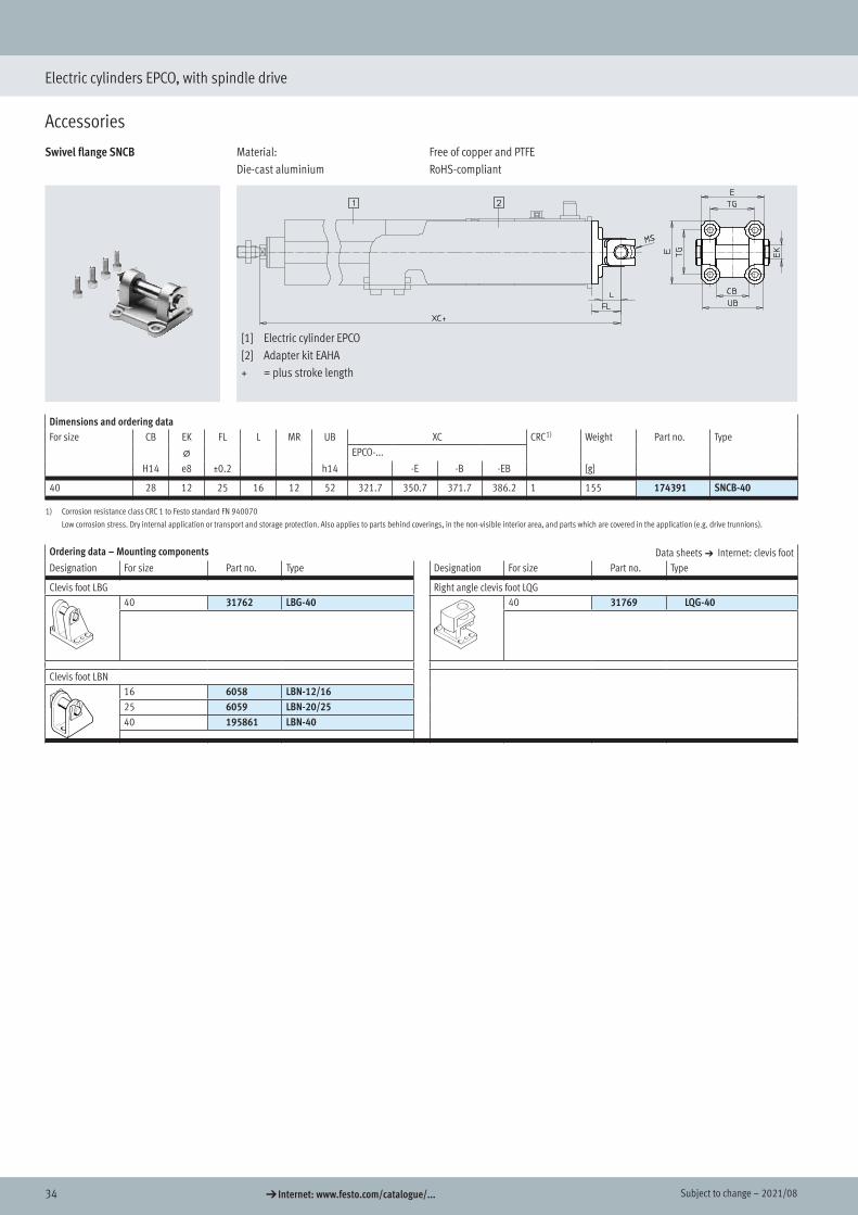
Swivel flange SNCB Material:Die-cast aluminium
Free of copper and PTFERoHS-compliant
[1] Electric cylinder EPCO[2] Adapter kit EAHA+ = plus stroke length
Dimensions and ordering dataFor size CB EK FL L MR UB XC CRC1) Weight Part no. Type
@ EPCO-...
H14 e8 ±0.2 h14 -E -B -EB [g]
40 28 12 25 16 12 52 321.7 350.7 371.7 386.2 1 155 174391 SNCB-40
1) Corrosion resistance class CRC 1 to Festo standard FN 940070
Low corrosion stress. Dry internal application or transport and storage protection. Also applies to parts behind coverings, in the non-visible interior area, and parts which are covered in the application (e.g. drive trunnions).
Ordering data – Mounting components Data sheets a Internet: clevis footDesignation For size Part no. Type Designation For size Part no. Type
Clevis foot LBG Right angle clevis foot LQG 40 31762 LBG-40 40 31769 LQG-40
Clevis foot LBN 16 6058 LBN-12/1625 6059 LBN-20/2540 195861 LBN-40
352021/08 – Subject to change d Internet: www.festo.com/catalogue/...
Electric cylinders EPCO, with spindle drive
Accessories
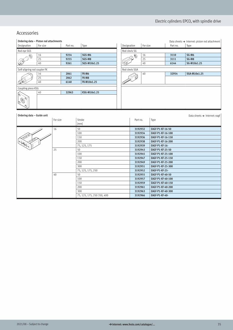
Ordering data – Piston rod attachments Data sheets a Internet: piston rod attachmentDesignation For size Part no. Type Designation For size Part no. Type
Rod eye SGS Rod clevis SG 16 9254 SGS-M6 16 3110 SG-M625 9255 SGS-M8 25 3111 SG-M840 9261 SGS-M10x1.25 40 6144 SG-M10x1.25
Self-aligning rod coupler FK Rod clevis SGA 16 2061 FK-M6 40 32954 SGA-M10x1.2525 2062 FK-M840 6140 FK-M10x1.25
Coupling piece KSG 40 32963 KSG-M10x1.25
Ordering data – Guide unit Data sheets a Internet: eagfFor size Stroke
[mm]Part no. Type
16 50 3192932 EAGF-P1-KF-16-50100 3192934 EAGF-P1-KF-16-100150 3192936 EAGF-P1-KF-16-150200 3192938 EAGF-P1-KF-16-20075, 125, 175 3192939 EAGF-P1-KF-16-
25 50 3192943 EAGF-P1-KF-25-50100 3192945 EAGF-P1-KF-25-100150 3192947 EAGF-P1-KF-25-150200 3192949 EAGF-P1-KF-25-200300 3192951 EAGF-P1-KF-25-30075, 125, 175, 250 3192952 EAGF-P1-KF-25-
40 50 3192955 EAGF-P1-KF-40-50100 3192957 EAGF-P1-KF-40-100150 3192959 EAGF-P1-KF-40-150200 3192961 EAGF-P1-KF-40-200300 3192963 EAGF-P1-KF-40-30075, 125, 175, 250 350, 400 3192966 EAGF-P1-KF-40-
Rod eye
Self-aligning rod coupler
Coupling piece
Rod clevis
Guide unit

36 d Internet: www.festo.com/catalogue/... Subject to change – 2021/08
Electric cylinders EPCO, with spindle drive
Accessories
Ordering data – Proximity switches for T-slot, magneto-resistive Data sheets a Internet: smtType of mounting Switching
outputElectrical connection Cable length Part no. Type
[m]
N/O contactInsertable in the slot from above, flush with the cylinder profile, short design
PNP Cable, 3-wire 2.5 574335 SMT-8M-A-PS-24V-E-2.5-OEPlug M8x1, 3-pin 0.3 574334 SMT-8M-A-PS-24V-E-0.3-M8DPlug M12x1, 3-pin 0.3 574337 SMT-8M-A-PS-24V-E-0.3-M12
NPN Cable, 3-wire 2.5 574338 SMT-8M-A-NS-24V-E-2.5-OEPlug M8x1, 3-pin 0.3 574339 SMT-8M-A-NS-24V-E-0.3-M8D
N/C contactInsertable in the slot from above, flush with the cylinder profile, short design
PNP Cable, 3-wire 7.5 574340 SMT-8M-A-PO-24V-E-7,5-OE
Ordering data – Proximity switches for T-slot, magnetic reed Data sheets a Internet: smeType of mounting Switching
outputElectrical connection Cable length Part no. Type
[m]
N/O contactInsertable in the slot from above, flush with the cylinder profile
Contacting Cable, 3-wire 2.5 543862 SME-8M-DS-24V-K-2.5-OE5.0 543863 SME-8M-DS-24V-K-5.0-OE
Cable, 2-wire 2.5 543872 SME-8M-ZS-24V-K-2.5-OEPlug M8x1, 3-pin 0.3 543861 SME-8M-DS-24V-K-0.3-M8D
N/C contactInsertable in the slot lengthwise, flush with the cylinder profile
Contacting Cable, 3-wire 7.5 160251 SME-8-O-K-LED-24
H- - Note
Position sensing is only possible in combination with characteristic "A" a page 26 (modular product system)
Ordering data – Connecting cable Data sheets a Internet: nebuDescription Connection Cable length Part no. Type
[m]
Straight socketUnion nut M8, both ends 3-pin 0.5 541346 NEBU-M8G3-K-0.5-M8G3
1.0 541347 NEBU-M8G3-K-1-M8G32.5 541348 NEBU-M8G3-K-2.5-M8G35.0 541349 NEBU-M8G3-K-5-M8G3
Proximity switch
Connecting cable
372021/08 – Subject to change d Internet: www.festo.com/catalogue/...
Electric cylinders EPCO, with spindle drive
Accessories
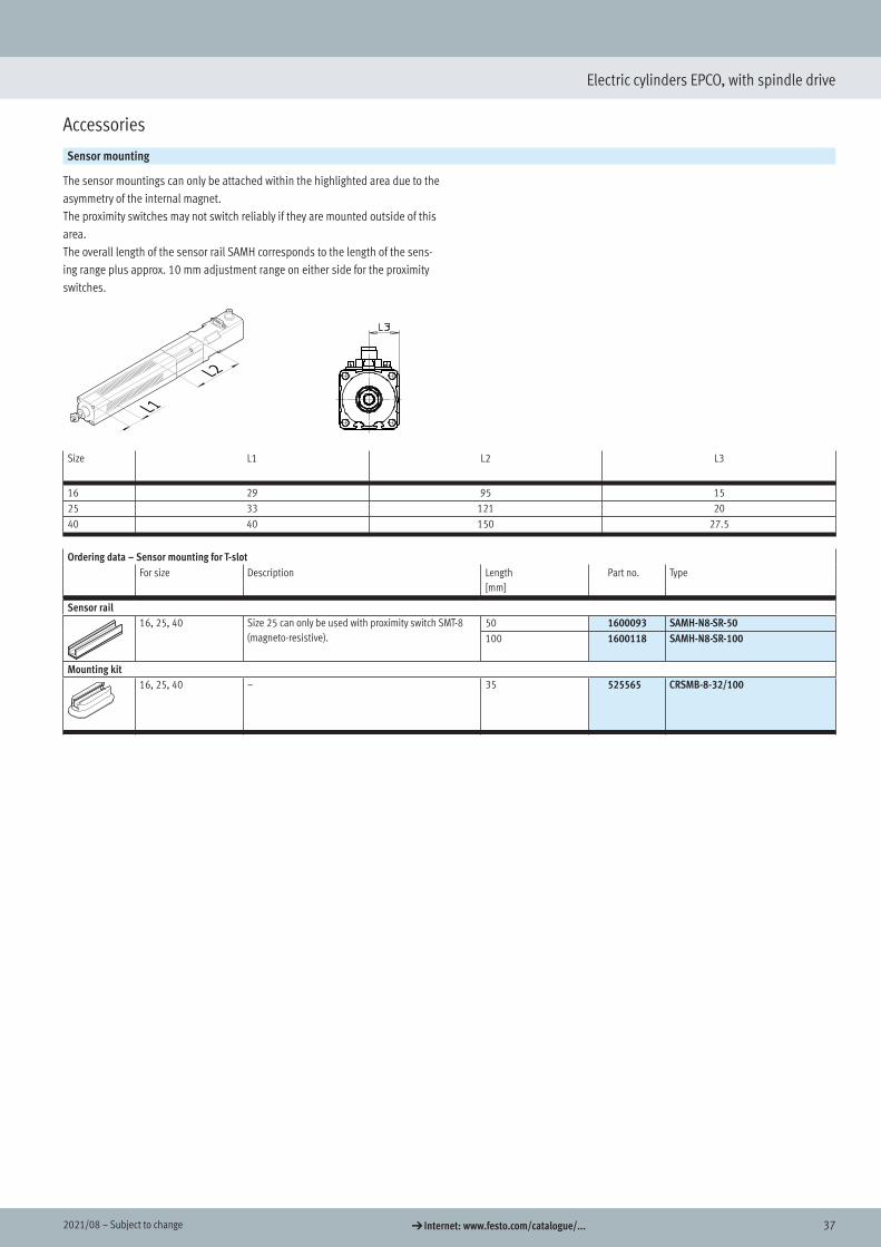
Sensor mounting
The sensor mountings can only be attached within the highlighted area due to the asymmetry of the internal magnet.The proximity switches may not switch reliably if they are mounted outside of this area.The overall length of the sensor rail SAMH corresponds to the length of the sens-ing range plus approx. 10 mm adjustment range on either side for the proximity switches.
Size L1 L2 L3
16 29 95 1525 33 121 2040 40 150 27.5
Ordering data – Sensor mounting for T-slotFor size Description Length
[mm]Part no. Type
Sensor rail16, 25, 40 Size 25 can only be used with proximity switch SMT-8
(magneto-resistive).50 1600093 SAMH-N8-SR-50100 1600118 SAMH-N8-SR-100
Mounting kit16, 25, 40 – 35 525565 CRSMB-8-32/100
Sensor mounting
Sensor rail
Mounting kit

38 d Internet: www.festo.com/catalogue/... Subject to change – 2021/08
Electric cylinders EPCO, with spindle drive
Accessories
Ordering data – Cables1)
For size Description Cable length[m]
Part no. Type
Motor cable16 Straight plug
• Min. bending radius: 62 mm• Suitable for energy chains• Ambient temp.:
–40 ... +80°C
1.5 1449600 NEBM-SM12G8-E-1.5-Q5-LE62.5 1449601 NEBM-SM12G8-E-2.5-Q5-LE65.0 1449602 NEBM-SM12G8-E-5-Q5-LE67.0 1449603 NEBM-SM12G8-E-7-Q5-LE610.0 1449604 NEBM-SM12G8-E-10-Q5-LE6
25/-40 Angled plug• Min. bending radius: 62 mm• Suitable for energy chains• Ambient temp.:
–40 ... +80°C
1.5 1450736 NEBM-S1W9-E-1.5-Q5-LE62.5 1450737 NEBM-S1W9-E-2.5-Q5-LE65.0 1450738 NEBM-S1W9-E-5-Q5-LE67.0 1450739 NEBM-S1W9-E-7-Q5-LE610.0 1450740 NEBM-S1W9-E-10-Q5-LE6
Straight plug• Min. bending radius: 62 mm• Suitable for energy chains• Ambient temp.:
–40 ... +80°C
1.5 1450368 NEBM-S1G9-E-1.5-Q5-LE62.5 1450369 NEBM-S1G9-E-2.5-Q5-LE65.0 1450370 NEBM-S1G9-E-5-Q5-LE67.0 1450371 NEBM-S1G9-E-7-Q5-LE610.0 1450372 NEBM-S1G9-E-10-Q5-LE6
Encoder cable16/-25/-40 Straight plug
• Min. bending radius: 68 mm• Suitable for energy chains• Ambient temp.:
–40 ... +80°C
1.5 1451586 NEBM-M12G8-E-1.5-LE82.5 1451587 NEBM-M12G8-E-2.5-LE85.0 1451588 NEBM-M12G8-E-5-LE87.0 1451589 NEBM-M12G8-E-7-LE810.0 1451590 NEBM-M12G8-E-10-LE8
25/-40 Angled plug• Min. bending radius: 68 mm• Suitable for energy chains• Ambient temp.:
–40 ... +80°C
1.5 1451674 NEBM-M12W8-E-1.5-LE82.5 1451675 NEBM-M12W8-E-2.5-LE85.0 1451676 NEBM-M12W8-E-5-LE87.0 1451677 NEBM-M12W8-E-7-LE810.0 1451678 NEBM-M12W8-E-10-LE8
1) Other cable lengths on request.
Ordering data – Motor controller Data sheets a Internet: cmmoDescription Part no. Type
With I/O interfaceSwitching input/output PNP 1512316 CMMO-ST-C5-1-DIOPSwitching input/output NPN 1512317 CMMO-ST-C5-1-DIONWith IO-LinkSwitching input/output PNP 1512320 CMMO-ST-C5-1-LKP
Motor cable
Encoder cable
Motor controller

Festo - Your Partner in Automation
www.festo.com
Connect with us
www.festo.com/socialmedia
1 Festo Inc. 2 Festo Pneumatic 3 Festo Corporation 4 Regional Service Center
5300 Explorer DriveMississauga, ON L4W 5G4Canada
Av. Ceylán 3,Col. Tequesquináhuac54020 Tlalnepantla, Estado de México
1377 Motor ParkwaySuite 310Islandia, NY 11749
7777 Columbia RoadMason, OH 45040
Festo Customer Interaction CenterTel: 1 877 463 3786Fax: 1 877 393 3786Email: [email protected]
Multinational Contact Center01 800 337 8669
Festo Customer Interaction Center1 800 993 37861 800 963 3786
Subj
ect t
o ch
ange


![Electric cylinders EPCO, with spindle drive · 2019-10-12 · Spindle design 3P 8P 3P 10P 5P 12.7P Spindle pitch1) [mm/rev] 3 8 3 10 5 12.7 Spindle diameter [mm] 8 8 10 10 12 12.7](https://static.fdocuments.us/doc/165x107/5f01fbb37e708231d401ff6d/electric-cylinders-epco-with-spindle-drive-2019-10-12-spindle-design-3p-8p-3p.jpg)