Santa Monica Homes for Sale | Call Kim and Kristine (310) 737-8173
www.lotsab.se +46 8 711 22 11
EkoTek System Installation and Configuration Manual
Survey
Installation
Configuration
Maintenance

EkoTek System Installation and Configuration Manual
9261-8173 issue: 9 Page i
Table of contents
Compliance ........................................................................................................................................... 4
FCC and Industry Canada Statement of Compliance ............................................................................ 4
WEEE Directive and Product Disposal .................................................................................................. 4
1. EkoTek principles .............................................................................................................................. 6
2. Location reporting ............................................................................................................................ 7
3. Alarms .............................................................................................................................................. 8
4. Location alarm ................................................................................................................................. 8
5. Beacons ............................................................................................................................................ 8
6. Two-way acknowledgement ............................................................................................................ 8
7. Two-way radio .................................................................................................................................. 8
8. Frequency hopping ........................................................................................................................... 9
9. ESPA and TAP paging I/O ................................................................................................................. 9
10. Configuration ................................................................................................................................. 9
11. Network parameters .................................................................................................................... 10
12. Diagnostics and statistics ............................................................................................................. 10
1. Hub ................................................................................................................................................. 11
2. Repeater and mains-powered repeater ......................................................................................... 11
3. Call point and mains-powered call point ........................................................................................ 12
4. Solar repeater (available on existing systems only) ....................................................................... 13
5. Call fob ........................................................................................................................................... 13
6. Pager .............................................................................................................................................. 14
7. Quad pager charging rack .............................................................................................................. 15
8. Call fob (Assist) ............................................................................................................................... 16
9. Pager (Assist) .................................................................................................................................. 16
10. Multi-way pager & fob charging racks (Assist) ............................................................................ 17
EkoTek System Installation and Configuration Manual
9261-8173 issue: 9 Page ii
1. Overview......................................................................................................................................... 18
1. Overview......................................................................................................................................... 20
2. Prerequisites ................................................................................................................................... 20
3. Placement rules .............................................................................................................................. 20
4. The survey unit ............................................................................................................................... 21
5. How to survey ................................................................................................................................. 24
1. Preparation .................................................................................................................................... 25
2. Installing the hub and IP slave hub ................................................................................................. 26
3. Installing the repeater, mains powered repeater and call point .................................................... 27
4. Installing the solar repeater ........................................................................................................... 30
5. Installing Synchronised Ethernet Repeater (SER) ........................................................................... 33
6. Installing the PPP modem .............................................................................................................. 34
7. Installing the four-way pager charging rack .................................................................................. 40
8. Browser interface setup ................................................................................................................. 41
9. Main menus .................................................................................................................................... 44
10. Maintenance menus ..................................................................................................................... 47
11. Configuration menus .................................................................................................................... 50
1. Overview......................................................................................................................................... 53
13. Final checks .................................................................................................................................. 74
14. Configuring SERs........................................................................................................................... 75
1. Personal security messages ............................................................................................................ 79
2. Pager response messages .............................................................................................................. 79
3. Maintenance messages .................................................................................................................. 79
1. Overview......................................................................................................................................... 82
2. Overlapping and mobile roaming systems ..................................................................................... 82
1. Overview......................................................................................................................................... 84
1. Overview of logging ....................................................................................................................... 85

EkoTek System Installation and Configuration Manual
9261-8173 issue: 9 Page iii
2. General formatting ......................................................................................................................... 85
3. Log examples .................................................................................................................................. 87
1. Revision history .............................................................................................................................. 93
2. Related documentation .................................................................................................................. 93
EkoTek System Installation and Configuration Manual
9261-8173 issue: 9 Page 4
Approvals
Compliance
This product complies with the requirements of the EU Radio & Telecommunications Terminal Equipment Directive 99/5/EC.
FCC and Industry Canada Statement of Compliance
This device complies with Part 15 of the FCC Rules and Industry Canada Standard RSS 210.
Operation is subject to the following two conditions: (1) this device may not cause harmful interference and (2) this device must accept any interference that may cause undesired operation.
Unauthorised modification to this equipment will void the user's authority to continue to operate the device within the scope of the Industry Canada and FCC Part 15 Rules.
A full technical specification for this product may be obtained from your Multitone representative.
WEEE Directive and Product Disposal
At the end of its serviceable life, this product should not be treated as household or general waste. It should be handed over to the applicable collection point for the recycling of electrical and electronic equipment, or returned to the supplier for disposal.
EkoTek System Installation and Configuration Manual
9261-8173 issue: 9 Page 5
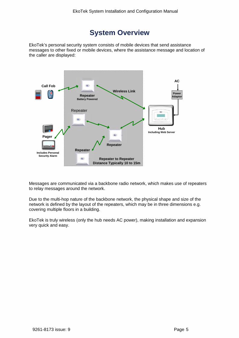
System Overview EkoTek’s personal security system consists of mobile devices that send assistance messages to other fixed or mobile devices, where the assistance message and location of the caller are displayed:
Includes Personal Security Alarm
HubIncluding Web Server
Repeater
Wireless LinkCall Fob
Pager
Repeater to RepeaterDistance Typically 10 to 15m
Repeater
Repeater
RepeaterBattery Powered
PowerAdaptor
AC
Messages are communicated via a backbone radio network, which makes use of repeaters to relay messages around the network.
Due to the multi-hop nature of the backbone network, the physical shape and size of the network is defined by the layout of the repeaters, which may be in three dimensions e.g. covering multiple floors in a building.
EkoTek is truly wireless (only the hub needs AC power), making installation and expansion very quick and easy.
EkoTek System Installation and Configuration Manual
9261-8173 issue: 9 Page 6
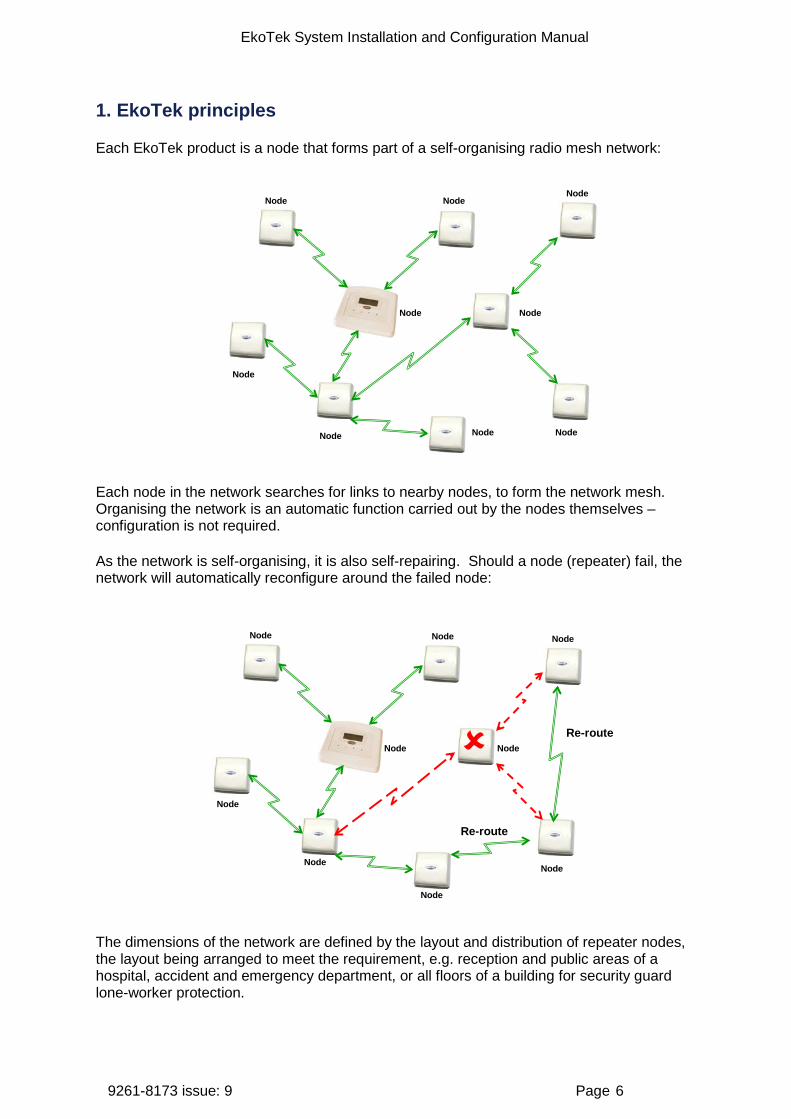
1. EkoTek principles
Each EkoTek product is a node that forms part of a self-organising radio mesh network:
Node NodeNode
Node
Node Node
Node
Node
Node
Each node in the network searches for links to nearby nodes, to form the network mesh. Organising the network is an automatic function carried out by the nodes themselves – configuration is not required.
As the network is self-organising, it is also self-repairing. Should a node (repeater) fail, the network will automatically reconfigure around the failed node:
Node Node Node
Node
Node
Node
Node
Node
Node
Re-route
Re-route
The dimensions of the network are defined by the layout and distribution of repeater nodes, the layout being arranged to meet the requirement, e.g. reception and public areas of a hospital, accident and emergency department, or all floors of a building for security guard lone-worker protection.
EkoTek System Installation and Configuration Manual
9261-8173 issue: 9 Page 7
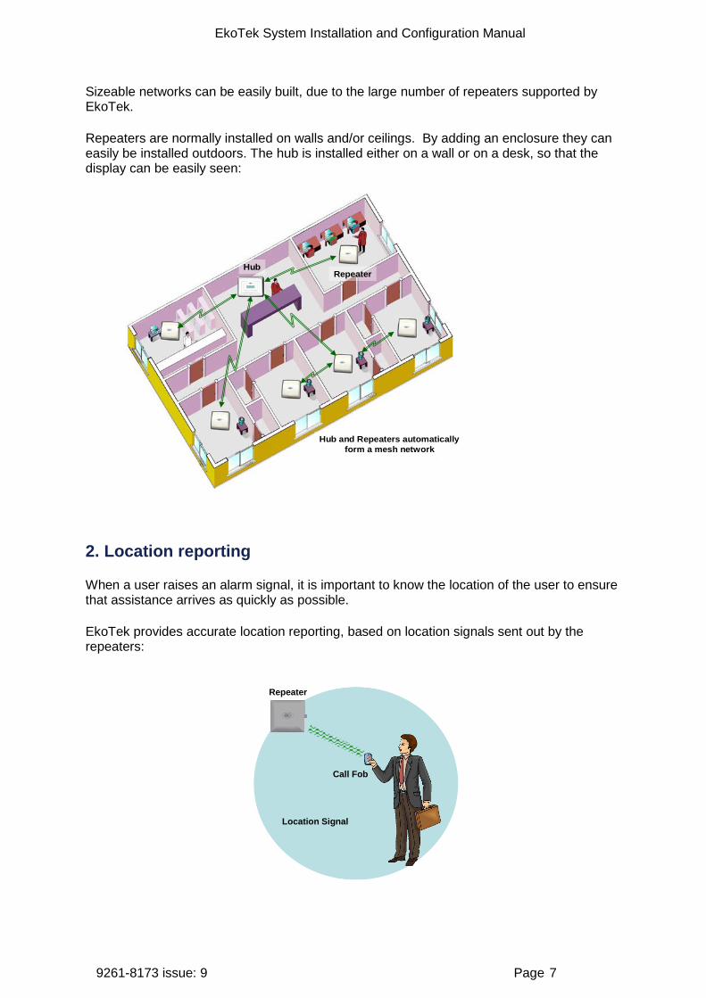
Sizeable networks can be easily built, due to the large number of repeaters supported by EkoTek.
Repeaters are normally installed on walls and/or ceilings. By adding an enclosure they can easily be installed outdoors. The hub is installed either on a wall or on a desk, so that the display can be easily seen:
HubRepeater
Hub and Repeaters automaticallyform a mesh network
2. Location reporting
When a user raises an alarm signal, it is important to know the location of the user to ensure that assistance arrives as quickly as possible.
EkoTek provides accurate location reporting, based on location signals sent out by the repeaters:
Repeater
Call Fob
Location Signal

EkoTek System Installation and Configuration Manual
9261-8173 issue: 9 Page 8
3. Alarms
A user may manually signal an alarm by pressing the red button on a pager or call fob, or alarms may be triggered automatically for man down, dead man or location alarms. When an alarm is triggered the user identification (name), location and alarm type are included in the alarm message displayed on the hub and sent to pagers.
Assist – Blue button
The Pagers (Assist) & Fobs (Assist) also have a Blue button added which is a lower level alert. This allows the user to call to request ‘Assistance’ when needed. The Red button in all products remains as an ‘Emergency’ button. When the Blue button is pressed it sends out a pre-programmed text message, there are no escalation and no requirement to clear alert. [Not available on previous mobile devices]
4. Location alarm
The location alarm feature allows pagers and call fobs to automatically raise an alarm should the device wearer enter a location where the local repeater indicates an unauthorised zone. Applications include ‘resident wander’, where an alarm would be raised if a resident wandered into a zone where they were not expected or not allowed, and ‘contractor/visitor’ location alarm where an alarm could be raised if a person entered a part of the building that they were not authorised to access.
5. Beacons
Beacon signals are used to update a device with information of who its parent is. The hub and all repeaters regularly transmit two types of beacon – system beacons and location beacons. Location beacons generally have a shorter range than System beacons. A repeater, pager or call fob can only ever have one parent at a time. Every 1000ms the repeater transmits to the pager or call fob, which is then updated with its location and will continue to receive subsequent beacons from the repeater (its parent). If the pager stays within range of the location beacon the location will be shown on the pager's display, ‘= [location name]’ (for example, ‘= Conference Room 1’). If the pager goes out of range of the location beacon but can still receive the system beacon, ‘- [location name]’ will be shown instead, where [location name] is the name of the last location beacon received. When a pager or call fob receives a new location beacon it picks up location information from the new repeater and updates itself with the new location.
6. Two-way acknowledgement
Messages from external systems and maintenance messages are one-way messages from the hub to the pager, whereas alarms generated by a user are two-way. For peace of mind of the user, the acceptance of an alarm at the hub or a pager by someone who will be coming to the aid of the user is signalled back to the user by the call fob lamp and beeper changing their alert patterns, or by the pager display indicating the status of the alarm.
7. Two-way radio
All EkoTek radio links are two-way, providing the ability to signal both to and from all devices on the network.
EkoTek System Installation and Configuration Manual
9261-8173 issue: 9 Page 9
Two-way radio provides the ability to quickly detect and correct any lost messages, for example, when a message is relayed from one repeater to a second repeater, the second repeater will acknowledge receipt of the message. If the first repeater does not receive an acknowledgement it retransmits the message. This ability allows EkoTek to function, even in environments where there is radio interference or poor signal.
A further benefit of two-way radio is the ability to download configuration parameters to all devices from the hub, using over-the-air programming. Fixed devices do not hold their own configuration, as this is sent by the hub upon request when each one is powered up. Even pagers and call fobs have their configuration held at the hub, making it unnecessary to recall mobile devices for configuration change, as all updates are made centrally at the hub.
8. Frequency hopping
EkoTek radio links can be configured to operate on a fixed frequency, or to hop across all 16 available frequencies. Frequency hopping increases the immunity of EkoTek systems to radio interference. If a message is lost due to interference on a frequency, the loss is immediately detected and the message retransmitted on the next frequency in the hopping sequence.
Frequency hopping is especially useful where the local radio environment may be unknown, or subject to change. EkoTek’s combination of message loss detection, automatic message retransmission and frequency hopping, makes for a very robust radio infrastructure.
9. ESPA and TAP paging I/O
In addition to the in-built support for EkoTek two-way pagers, the hub provides the ability to connect the EkoTek system to external systems via a one-way paging interface. This allows the EkoTek system to either receive or to send messages to a pre-existing one-way paging system.
The hub paging interface can be selected from ESPA or TAP as an input or output through Port A and by using Port B TAP or ESPA input only. This allows EkoTek to be used as a paging system, e.g. for connection to a nurse call system or to send messages to a pre-existing one-way paging system.
10. Configuration
All configuration of the EkoTek system is performed via web pages stored on the EkoTek hub. Access to this web server is either via the 10/100Base-T Ethernet port or using PPP via an RS232 serial port. Configuration for all devices is held on the hub and downloaded to each device at power-up.
The hub defaults allow a new system to operate ‘out-of-the-box’, only requiring the location names for the repeaters and user names for the mobile devices to be entered on the hub’s web server configuration page.
Each device has its own unique factory set serial number for identification, but there is no factory programming of the devices. The hub configuration set for the devices during installation defines whether device options (e.g. the man down alarm) are enabled or not.
EkoTek System Installation and Configuration Manual
9261-8173 issue: 9 Page 10
11. Network parameters
An EkoTek system controlled by a single hub is able to support up to 500 devices in this release. See Appendix 2: Specifications for maximum numbers for each type of device.
The network radio channels can be configured using the hub web server interface, with up to 16 channels being available for simultaneous use by a single EkoTek system. The default configuration is for all EkoTek devices to use channel 15. See the Multitone document ‘Example EkoTek System Configurations’ for more information on special configurations.
A single EkoTek radio channel can support up to 90 repeaters, but a limitation of 70 per channel is recommended to allow for dynamic reconfiguration (silent parent swapping). The repeaters can be configured in any physical deployment, as long as each repeater is able to establish and maintain a suitably strong signal with a nearby repeater that has a path back to the hub.
12. Diagnostics and statistics
Each EkoTek device collects statistics on network performance. These statistics are regularly sent to the hub and can be viewed using the web server.
Failure (e.g. loss of network coverage) and battery low indications for EkoTek devices are displayed on the status screen of the web interface; these messages are also reported on the hub and/or pager displays if the option to do this is configured.
EkoTek System Installation and Configuration Manual
9261-8173 issue: 9 Page 11
Components
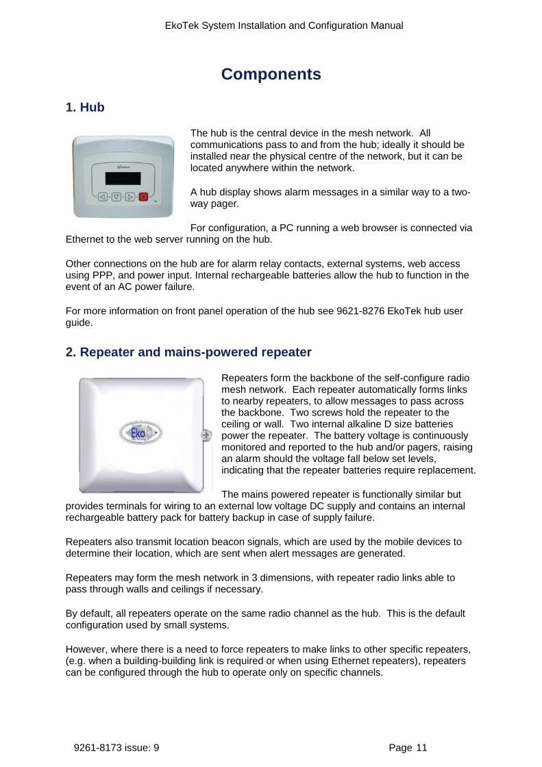
1. Hub
The hub is the central device in the mesh network. All communications pass to and from the hub; ideally it should be installed near the physical centre of the network, but it can be located anywhere within the network.
A hub display shows alarm messages in a similar way to a two-way pager.
For configuration, a PC running a web browser is connected via Ethernet to the web server running on the hub.
Other connections on the hub are for alarm relay contacts, external systems, web access using PPP, and power input. Internal rechargeable batteries allow the hub to function in the event of an AC power failure.
For more information on front panel operation of the hub see 9621-8276 EkoTek hub user guide.
2. Repeater and mains-powered repeater
Repeaters form the backbone of the self-configure radio mesh network. Each repeater automatically forms links to nearby repeaters, to allow messages to pass across the backbone. Two screws hold the repeater to the ceiling or wall. Two internal alkaline D size batteries power the repeater. The battery voltage is continuously monitored and reported to the hub and/or pagers, raising an alarm should the voltage fall below set levels, indicating that the repeater batteries require replacement.
The mains powered repeater is functionally similar but provides terminals for wiring to an external low voltage DC supply and contains an internal rechargeable battery pack for battery backup in case of supply failure.
Repeaters also transmit location beacon signals, which are used by the mobile devices to determine their location, which are sent when alert messages are generated.
Repeaters may form the mesh network in 3 dimensions, with repeater radio links able to pass through walls and ceilings if necessary.
By default, all repeaters operate on the same radio channel as the hub. This is the default configuration used by small systems.
However, where there is a need to force repeaters to make links to other specific repeaters, (e.g. when a building-building link is required or when using Ethernet repeaters), repeaters can be configured through the hub to operate only on specific channels.

EkoTek System Installation and Configuration Manual
9261-8173 issue: 9 Page 12
Battery replacement for the repeater is quickly achieved by sliding the repeater from the backing plate and lifting out the old batteries. No tools are required for this. An optional locking screw can be inserted where necessary to help prevent tampering with the repeater, for example, where the repeater is installed in a public environment, within reach of passers by.
Repeaters continually test links to adjacent repeaters, detecting link failures and automatically searching for and establishing new links should one fail.
Network moves and/or expansion are achieved by moving or adding new repeaters where required, making any network changes rapid and cost effective.
3. Call point and mains-powered call point
The call point allows alarms and assist calls to be raised by a red button on the front of the unit or an external closing contact input.
A call point can be used to connect to equipment that has a closing contact (a simple switch such as a ceiling mounted pull cord) to signal an alarm.
The assist message is configurable separately for the red button and external contact input.
The call point has an internal sounder (configurable on/off) to indicate call state.
The red button can be configured as either:
1. Disabled.
2. Single press raises alarm.
3. Double press raises alarm.
A long press of the red button always clears an alarm raised by the red button or the external alarm contact.
The mains powered call point is functionally similar but provides terminals for wiring to an external low voltage DC supply and contains an internal rechargeable battery pack for battery backup in case of supply failure.
The call point can also be used as a repeater while still retaining call point functionality. For mounting positions where the unit is at body height this is not recommended, as the quality of link that the call point can offer will degrade when someone stands near or in front of the unit. This may cause devices communicating through the call point repeater to lose contact with the network. For high positions such as operating in conjunction with a ceiling pull cord this should not be a problem.
EkoTek System Installation and Configuration Manual
9261-8173 issue: 9 Page 13
A situation where repeater operation may be acceptable if the unit is at body height is to allow the unit to be a repeater for mobile devices only. This can be achieved by setting the call point’s ‘Downstream channel’ to a channel that other repeaters cannot use as an ‘Upstream channel’.
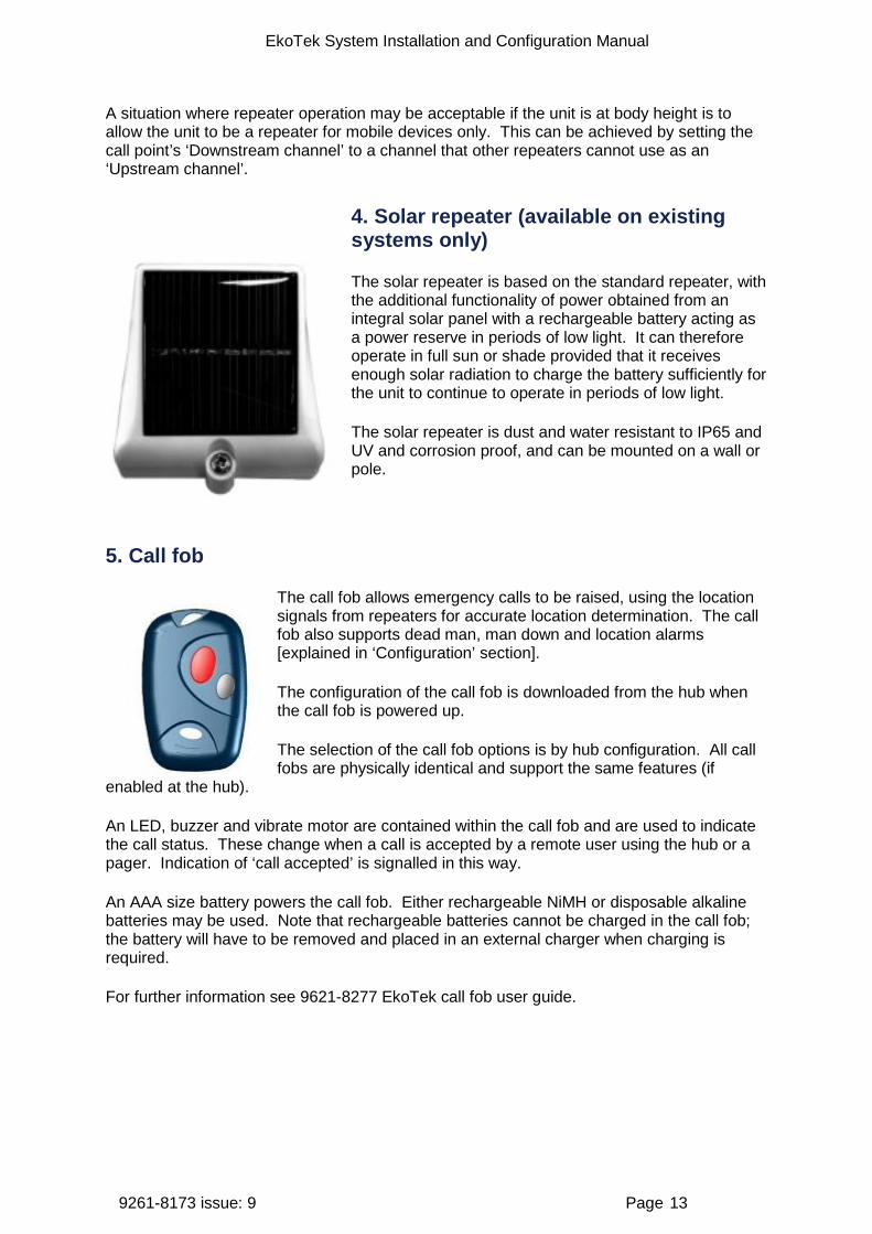
4. Solar repeater (available on existing systems only)
The solar repeater is based on the standard repeater, with the additional functionality of power obtained from an integral solar panel with a rechargeable battery acting as a power reserve in periods of low light. It can therefore operate in full sun or shade provided that it receives enough solar radiation to charge the battery sufficiently for the unit to continue to operate in periods of low light.
The solar repeater is dust and water resistant to IP65 and UV and corrosion proof, and can be mounted on a wall or pole.
5. Call fob
The call fob allows emergency calls to be raised, using the location signals from repeaters for accurate location determination. The call fob also supports dead man, man down and location alarms [explained in ‘Configuration’ section].
The configuration of the call fob is downloaded from the hub when the call fob is powered up.
The selection of the call fob options is by hub configuration. All call fobs are physically identical and support the same features (if
enabled at the hub).
An LED, buzzer and vibrate motor are contained within the call fob and are used to indicate the call status. These change when a call is accepted by a remote user using the hub or a pager. Indication of ‘call accepted’ is signalled in this way.
An AAA size battery powers the call fob. Either rechargeable NiMH or disposable alkaline batteries may be used. Note that rechargeable batteries cannot be charged in the call fob; the battery will have to be removed and placed in an external charger when charging is required.
For further information see 9621-8277 EkoTek call fob user guide.

EkoTek System Installation and Configuration Manual
9261-8173 issue: 9 Page 14
6. Pager
The pager has the following key functions:
Display of and response to emergency calls from other EkoTek devices Display of paging messages created using the hub’s web
server or an external system Raising emergency calls in a similar manner to the call fob Snatch cord operation (some models)
For further information see 9621-8275 EkoTek pager user guide.
EkoTek’s two-way radio network provides message interchange between devices, for example, when a call fob raises an emergency message this is displayed on the hub and the pagers. A pager or hub user can then accept the call, which is signalled back to the call fob and indicated to the user by a change in the LED and beep pattern being emitted by the call fob during the emergency call.
Paging messages can be generated either via the hub web server or an external system. Web server-originated pager messages can be configured to show delivery and request a ‘Yes/No’ response (only from EkoTek pagers with this two-way paging function); simple task management systems can be easily created.
In a similar way to call fobs, pagers are able to generate emergency calls using the red emergency button on the pager, the inbuilt man down or dead man functions, or location alarms. A pager can therefore function as both an alarm unit and a display, eliminating the need for users to carry both types of unit.
An AAA size battery powers the pager. Either rechargeable NiMH or disposable alkaline batteries may be used. Charging contacts on the pager are used when the pager is inserted into a charging rack. [Pager (Assist) devices are rechargeable batteries only]
Some pager devices are fitted with a snatch cord that is inserted into a socket on the body of the pager. The pager generates personal security assistance calls when the snatch cord is pulled and disconnected from the body of the pager when enabled. The snatch cord can be replaced with a blanking plug if this functionality is not required.

EkoTek System Installation and Configuration Manual
9261-8173 issue: 9 Page 15
7. Quad pager charging rack
The quad pager charging rack charges up to 4 pagers at one time in the rack, with a maximum charge times of 12 hours to charge a pager battery to 50% of its capacity.
The pager reports charging in its usual status report. An extra report is generated when a pager enters or leaves the charger so the hub can update its status quickly.
When a pager reports its battery status as charging, this is shown on the device status display.
Man down and dead man alarms are automatically disabled when a pager is inserted into the charging rack.
When a pager is installed in a charging rack, a user-configurable feature allows the pager to be set to receive or ignore messages, allowing the pager to continue to function in the charging rack if required.
The standard EkoTek PSU is used as the rack PSU and can be used to power up to two charging racks.
Note: The pager must be fitted with a NiMH rechargeable cell when used in a charging rack. Use of the charging rack with other types of cell may damage the pager. The Assist pagers must not be placed in this charging rack.
EkoTek System Installation and Configuration Manual
9261-8173 issue: 9 Page 16
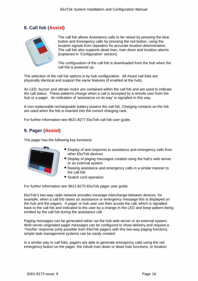
8. Call fob (Assist)
The call fob allows Assistance calls to be raised by pressing the blue button and Emergency calls by pressing the red button, using the location signals from repeaters for accurate location determination. The call fob also supports dead man, man down and location alarms [explained in ‘Configuration’ section].
The configuration of the call fob is downloaded from the hub when the call fob is powered up.
The selection of the call fob options is by hub configuration. All Assist call fobs are physically identical and support the same features (if enabled at the hub).
An LED, buzzer and vibrate motor are contained within the call fob and are used to indicate the call status. These patterns change when a call is accepted by a remote user from the hub or a pager. An indication of ‘assistance on its way’ is signalled in this way.
A non-replaceable rechargeable battery powers the call fob. Charging contacts on the fob are used when the fob is inserted into the correct charging rack.
For further information see 9621-8277 EkoTek call fob user guide.
9. Pager (Assist)
The pager has the following key functions:
Display of and response to assistance and emergency calls from other EkoTek devices Display of paging messages created using the hub’s web server
or an external system Raising assistance and emergency calls in a similar manner to
the call fob Snatch cord operation
For further information see 9621-8275 EkoTek pager user guide.
EkoTek’s two-way radio network provides message interchange between devices, for example, when a call fob raises an assistance or emergency message this is displayed on the hub and the pagers. A pager or hub user can then accept the call, which is signalled back to the call fob and indicated to the user by a change in the LED and beep pattern being emitted by the call fob during the assistance call.
Paging messages can be generated either via the hub web server or an external system. Web server-originated pager messages can be configured to show delivery and request a ‘Yes/No’ response (only possible from EkoTek pagers with this two-way paging function); simple task management systems can be easily created.
In a similar way to call fobs, pagers are able to generate emergency calls using the red emergency button on the pager, the inbuilt man down or dead man functions, or location

EkoTek System Installation and Configuration Manual
9261-8173 issue: 9 Page 17
alarms. A pager can therefore function as both an alarm unit and a display, eliminating the need for users to carry both types of unit.
A non-replaceable rechargeable battery powers the pager. Charging contacts on the pager are used when the pager is inserted into a charging rack.
10. Multi-way pager & fob charging racks (Assist)
The multi-way charging racks charge up to 4 pagers or 5 fobs at one time.
The Fob LEDs flash to show their charging status:
• Steady flash – charging • Dual flash - fully charged
A device charges to 50% of its charge in 12 hours and provides approx 8 hours of use from a 40 min charge.
Man-down and dead-man alarms are disabled when pagers are in the charger, but may be configured to receive or ignore messages when in the charger.
Power supplies are to be purchased separately from the multi-racks. The PSU can power up to 8 multi-racks at once.
Note: Non-Assist Fobs / Pagers must not be placed in these charging racks.
EkoTek System Installation and Configuration Manual
9261-8173 issue: 9 Page 18
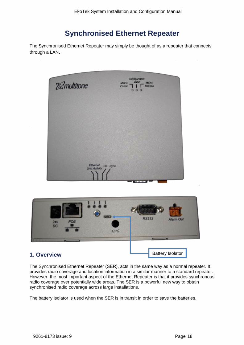
Synchronised Ethernet Repeater The Synchronised Ethernet Repeater may simply be thought of as a repeater that connects through a LAN.
1. Overview
The Synchronised Ethernet Repeater (SER), acts in the same way as a normal repeater. It provides radio coverage and location information in a similar manner to a standard repeater. However, the most important aspect of the Ethernet Repeater is that it provides synchronous radio coverage over potentially wide areas. The SER is a powerful new way to obtain synchronised radio coverage across large installations.
The battery isolator is used when the SER is in transit in order to save the batteries.
Battery Isolator
EkoTek System Installation and Configuration Manual
9261-8173 issue: 9 Page 19
If an external alarm is to be activated from the hub, connect a pair of wires from the alarm output shown in the interface connections above. The alarm output is a simple make/break contact and can be used to operate a customer provided alarm relay. This is not designed to provide a direct contact for AC mains operated equipment.
The upstream is connected to the hub via the LAN rather than as a radio link in the standard repeater.
The synchronous aspect should not be overlooked nor misunderstood – this is probably the most significant aspect of the SER.
When correctly configured, synchronised radio coverage is crucially important and supports the following functionality in EkoTek installations:
1. Replaces long chains of repeaters - linking between buildings would previously have required chains of repeaters to be set up.
2. Provides robust and reliable radio coverage – more effective in multi-floor environments because the radio path back to the hub is via LAN.
3. Up to 8 SERs can be connected to a single hub with one SER being master for system timing.
4. Allows the EkoTek hub to be remotely located on the customer’s LAN – previously required to be at the centre of the network coverage but can now be located in a Security Control Centre in a remote location.
5. Provides synchronised radio timing with other SER via the LAN. 6. Without synchronisation fixed networks could possibly interfere with each other and
mobile devices will not necessarily detect new networks.
Note: A stable and reliable customer LAN is essential when using SERs in the System.

EkoTek System Installation and Configuration Manual
9261-8173 issue: 9 Page 20
Network design and survey
1. Overview
The survey is used to assess the number of repeaters required and best locations for the repeaters. It is recommended that the surveyor reads the ‘System Overview’ section (page 5) to become familiar with the basic principles of operation.
2. Prerequisites
Two survey pagers (2WSU) Site plans Customer requirements Awareness of any WiFi in use
3. Placement rules
Each repeater connects to the hub or SER, either directly or via another repeater. The number of repeaters required depends on the size and layout of the building and the consistency of the radio coverage.
The EkoTek hub and repeaters must not be installed in areas where explosive gas or dust products may be present. Devices must be protected from liquids, extreme temperatures and strong magnetic fields. Do not install in places where they will be exposed to strong sunlight or electromagnetic interference.
Hub The hub should be placed in an area such as a control room or reception desk where it is possible to monitor the display when required. Other considerations are to minimise the number of hops required for any repeater to connect to the hub; it is better if possible that the hub be located at the centre of the network, unless using SERs. The hub must be located near an AC mains socket outlet and an Ethernet connection; it should also be borne in mind that connection via a modem link to the telephone network may be needed, so access to a telephone socket would also be necessary. It is important that there are multiple repeaters around the hub to ensure multiple paths to the rest of the network and overcome any possible ‘people blocking’ of the hub.
Repeaters Ideally repeaters should be spaced 10-15 metres apart. They should be no closer together than 6 metres, except where there is a structural barrier sufficient to attenuate the radio signal, such as a wall between repeaters. The maximum range is 20 metres, but placing repeaters at this distance should be avoided if possible, as any degradation of the radio path may result in the loss of connection between repeaters, distance will determined through a site survey.
For the positioning of a solar repeater see ‘Solar repeater positioning’.
Multi-storey buildings EkoTek can be used in multi-storey buildings, where the floors are of concrete construction. The concrete floor provides sufficient attenuation of the radio signal to ensure that the pager or call fob’s location is reported on the correct floor. In wooden floored buildings, the device
EkoTek System Installation and Configuration Manual
9261-8173 issue: 9 Page 21
may pick up a beacon from the floor above or even below, giving an inaccurate location for the device. Careful positioning of repeaters is therefore required when wooden or mezzanine floors are in use if location is important.
In order to establish which floor the pager or call fob is on, it is important that repeaters are placed at the entrances to the bottom and top of stairwells. The actual placement of the repeater may not necessarily be in the stairwell itself, but may be in a room leading to the stairwell, in order to provide sufficient radio separation between repeaters.
Corridors In long corridors it may be prudent to place a repeater in the middle of the corridor as well as at the ends, to ensure robust radio connection in the mesh.
Room placements If locating in individual rooms, place the repeater as central to the room as practical. Placing it on the edge of the room may allow sufficient strength of location signal to pass through the wall to be seen as a beacon by a device in the adjacent room or corridor.
It is however highly unlikely that the signal would pass through more than one wall.
In large rooms such as warehouses, it will be necessary to place more than one repeater to ensure adequate radio coverage.
Between buildings If buildings are sufficiently close together, radio signals may pass between them. However, if for example a vehicle passes between the buildings, it may cause signal deterioration and the repeater to lose contact with its parent. For this reason on a multi-storey building, it would be better to force the repeaters on the first floor to form the link between buildings. This is achieved by setting the downstream link of the parent on the first floor of one building to be a specific channel and the upstream link of the repeater on the first floor of the adjacent building to be also the same channel (unless using SERs).
Mesh structure A repeater can only have one parent at a time; however, the principle of a mesh network is that if a connection fails the repeater can search for an alternative parent in order to rejoin the network. If it is unable to locate a suitable new parent, its portion of the network will be broken. It is therefore important to ensure that any repeater has multiple potential paths to the hub.
4. The survey unit
The survey unit is designed to assist in the placement of repeaters and aid in trouble -shooting the network. It has several modes of operation, described below. The ▲▼buttons scroll through the menus. A long press on the button will switch the survey pager on and off.
When taking measurements always hold the pager by the left hand side to avoid masking the signal; the pager’s antenna is located on the right hand side. Also avoid placing your body between the pager and the measured device, as this will attenuate the signal.
Note: The survey pager is continuously transmitting a signal and its battery life is therefore short. To avoid unnecessarily draining the battery, switch off and/or remove the battery when not in use.
EkoTek System Installation and Configuration Manual
9261-8173 issue: 9 Page 22
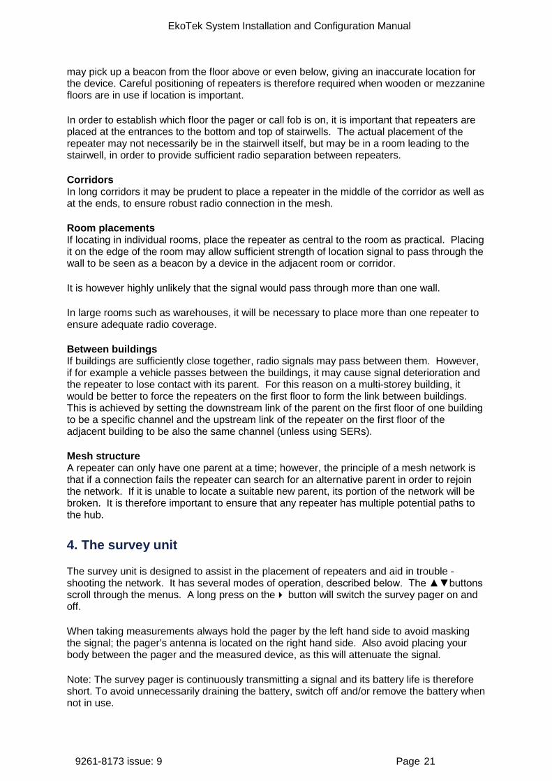
Survey pager modes RSSI
This screen indicates the signal strength for each channel in both the Rx and Tx paths. The measurement for each channel is displayed as a vertically stacked number. Ideally the RSSI should be 30 or above.
Quality
This screen indicates the quality for each channel in both the Rx and Tx paths. The measurement for each channel is displayed as a vertically stacked number. The range of reported values is 0 to 99 with 99 being the best quality. Ideally the quality should be 90 or above.
EkoTek System Installation and Configuration Manual
9261-8173 issue: 9 Page 23
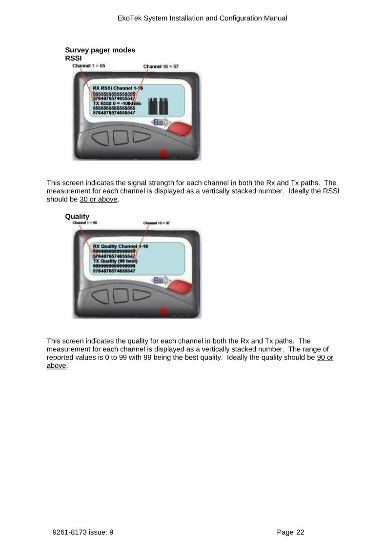
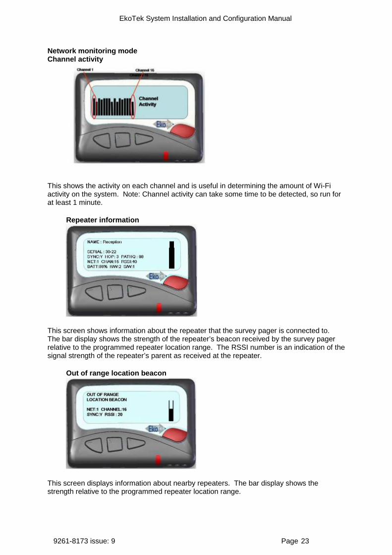
Network monitoring mode Channel activity
This shows the activity on each channel and is useful in determining the amount of Wi-Fi activity on the system. Note: Channel activity can take some time to be detected, so run for at least 1 minute.
Repeater information
This screen shows information about the repeater that the survey pager is connected to. The bar display shows the strength of the repeater’s beacon received by the survey pager relative to the programmed repeater location range. The RSSI number is an indication of the signal strength of the repeater’s parent as received at the repeater.
Out of range location beacon
This screen displays information about nearby repeaters. The bar display shows the strength relative to the programmed repeater location range.

EkoTek System Installation and Configuration Manual
9261-8173 issue: 9 Page 24
5. How to survey
Use a survey pager in “channel activity” mode to detect WiFi across site premises, and ask customer if they are aware of any WiFi.
Use a pair of survey pagers in RSSI mode to assess the attenuation caused by walls and partitions – it is not always possible to estimate from sight e.g. aluminium liners, and wire mesh in glass cause significant attenuation. It is not practical to survey every wall and floor but a representative few should give an understanding of the building construction.
Decide on the location for the hub. It is important that there are multiple repeaters around the hub to ensure multiple paths to the rest of the network and overcome any possible ‘people blocking’ of the hub.
Ask the customer which locations are critical for accurate call location reporting and mark on the plan those places as locations for repeaters. It may be every room, a defined area or different floors. In very large rooms use more than one repeater.
Also mark on the plan the positions for repeaters at the top and bottom of all stairwells, to allow location tracking between floors.
The customer may also want to have a location change when persons leave a critical area. If so, mark repeaters on the site plan at the exit of those critical areas.
When all the likely places for repeaters have been marked, inspect the site plan to estimate if the distance between repeaters exceeds the 10-15 metre maximum separation rule. If there appears to be a long gap between repeaters, consider if there are repeaters on the floor above or below that can form a path for the network.
If a repeater appears to be isolated, use survey pagers to check the RSSI. Place a pager at the repeater and measure the RSSI at its nearest neighbour. Remember its nearest neighbour may be on a different floor. If the nearest neighbour is the other side of a thick wall, other marked locations may provide a more viable route. If in doubt it is best to place in-fill repeaters, as the more repeaters in a network the more robust the network is liable to be. If the RSSI is below 20, then place another repeater in between.
EkoTek System Installation and Configuration Manual
9261-8173 issue: 9 Page 25
Installation
1. Preparation
Prerequisites Prior to installation, the following items are needed:
Site plans with position of the hub and all the likely repeater locations clearly marked An AC mains socket outlet for the hub An Ethernet connection to the customer LAN for the hub A working telephone line and AC mains socket for the PPP connection (if required) A line for external ESPA or TAP system connection (if required) Identify which PC is to be used for admin access and log file downloads If installing SERs they will need an AC mains socket outlet plus connection to the
customer’s LAN
Tools suggested Pozidriv screwdriver Screwdriver with 2.5mm blade Stepladder Cordless drill 5mm masonry bit 6mm masonry bit Metric rule Laptop with Ethernet port Ethernet patch cable Call fob and pager from customer system Survey pagers
Equipment required EkoTek hub with AC power supply unit If modem access to a telephone link is required then use current recommended modem
with AC supply unit and a RS232 (proprietary) connecting lead. See Appendix 3: RS232 cable pin-outs for connecting the modem to the hub
EkoTek repeaters: quantity as required by survey. It is also suggested that spare repeater/s are supplied, in case there is a need for infill that was not detected on the survey (Ethernet repeater/s as required)

EkoTek System Installation and Configuration Manual
9261-8173 issue: 9 Page 26
2. Installing the hub and IP slave hub
The hub can be freestanding on a desk, or wall mounted using the screws provided.
To remove the cover, depress the two protruding plastic tabs and separate the top from the back plate.
Wall mounting Mark the position of the screws on the wall. The two screws should be spaced precisely 120mm apart, as shown in the diagram of the back plate below:
Drill two holes with a 5mm masonry bit to a depth of 25mm.
Insert the wall plugs and screw the screws. Leave 7mm of the screw protruding. (Note: Screws and plugs not provided).
120mm
EkoTek System Installation and Configuration Manual
9261-8173 issue: 9 Page 27
Locate the screw heads in the holes in the back-plate and pull the unit down to lock into place.
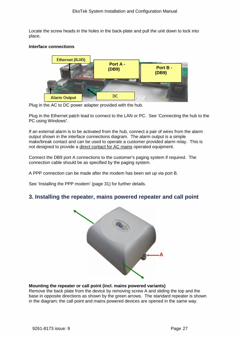
Interface connections
Plug in the AC to DC power adapter provided with the hub.
Plug in the Ethernet patch lead to connect to the LAN or PC. See ‘Connecting the hub to the PC using Windows’.
If an external alarm is to be activated from the hub, connect a pair of wires from the alarm output shown in the interface connections diagram. The alarm output is a simple make/break contact and can be used to operate a customer provided alarm relay. This is not designed to provide a direct contact for AC mains operated equipment.
Connect the DB9 port A connections to the customer's paging system if required. The connection cable should be as specified by the paging system.
A PPP connection can be made after the modem has been set up via port B.
See ‘Installing the PPP modem’ (page 31) for further details.
3. Installing the repeater, mains powered repeater and call point
Mounting the repeater or call point (incl. mains powered variants) Remove the back plate from the device by removing screw A and sliding the top and the base in opposite directions as shown by the green arrows. The standard repeater is shown in the diagram; the call point and mains powered devices are opened in the same way.
Port A - (DB9) Port B -
(DB9)
EkoTek System Installation and Configuration Manual
9261-8173 issue: 9 Page 28
When mounting the mains powered devices it may be easiest to detach the power cable from the circuit board first by gently pulling out the connector from the board. The mains powered repeater/call point may be supplied with the power cable already detached.
Use the back plate to mark the position of the screw holes on the wall or ceiling. The call point may be mounted at desk height but if it is also to be used as a repeater it should be mounted using the same criteria as a normal repeater. The contact for the call point should then be extended to a switch (such as a ceiling pull switch).
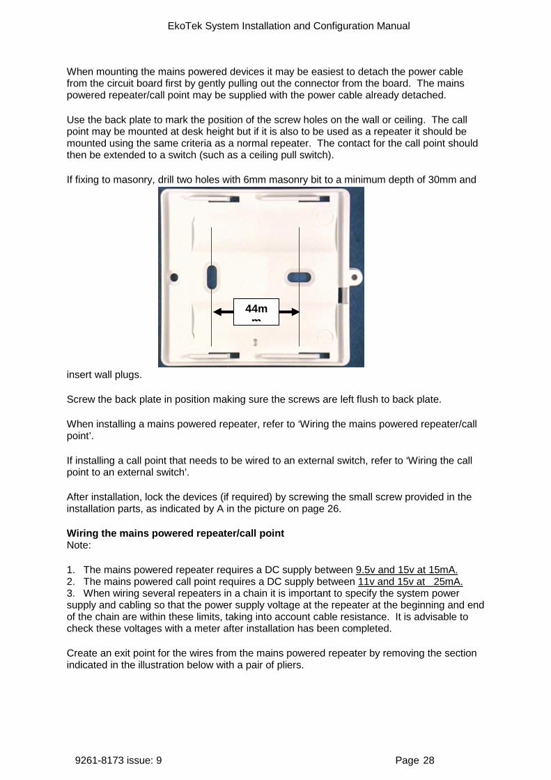
If fixing to masonry, drill two holes with 6mm masonry bit to a minimum depth of 30mm and
insert wall plugs.
Screw the back plate in position making sure the screws are left flush to back plate.
When installing a mains powered repeater, refer to ‘Wiring the mains powered repeater/call point’.
If installing a call point that needs to be wired to an external switch, refer to ‘Wiring the call point to an external switch’.
After installation, lock the devices (if required) by screwing the small screw provided in the installation parts, as indicated by A in the picture on page 26.
Wiring the mains powered repeater/call point Note:
1. The mains powered repeater requires a DC supply between 9.5v and 15v at 15mA. 2. The mains powered call point requires a DC supply between 11v and 15v at 25mA. 3. When wiring several repeaters in a chain it is important to specify the system power supply and cabling so that the power supply voltage at the repeater at the beginning and end of the chain are within these limits, taking into account cable resistance. It is advisable to check these voltages with a meter after installation has been completed.
Create an exit point for the wires from the mains powered repeater by removing the section indicated in the illustration below with a pair of pliers.
44mm
EkoTek System Installation and Configuration Manual
9261-8173 issue: 9 Page 29
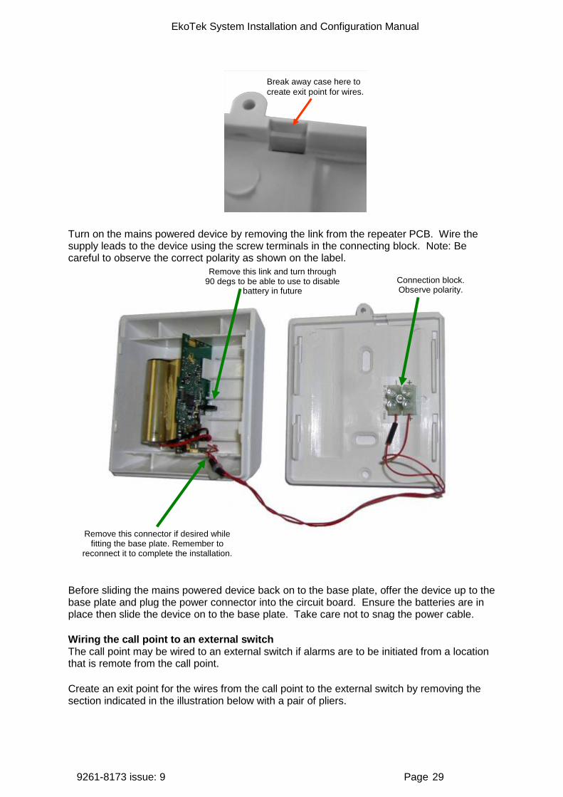
Break away case here to create exit point for wires.
Turn on the mains powered device by removing the link from the repeater PCB. Wire the supply leads to the device using the screw terminals in the connecting block. Note: Be careful to observe the correct polarity as shown on the label.
Before sliding the mains powered device back on to the base plate, offer the device up to the base plate and plug the power connector into the circuit board. Ensure the batteries are in place then slide the device on to the base plate. Take care not to snag the power cable.
Wiring the call point to an external switch The call point may be wired to an external switch if alarms are to be initiated from a location that is remote from the call point.
Create an exit point for the wires from the call point to the external switch by removing the section indicated in the illustration below with a pair of pliers.
Remove this connector if desired while fitting the base plate. Remember to
reconnect it to complete the installation.
Connection block. Observe polarity.
Remove this link and turn through 90 degs to be able to use to disable
battery in future
EkoTek System Installation and Configuration Manual
9261-8173 issue: 9 Page 30
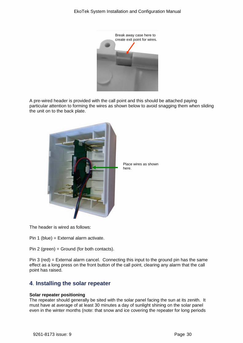
Break away case here to create exit point for wires.
A pre-wired header is provided with the call point and this should be attached paying particular attention to forming the wires as shown below to avoid snagging them when sliding the unit on to the back plate.
The header is wired as follows:
Pin 1 (blue) = External alarm activate.
Pin 2 (green) = Ground (for both contacts).
Pin 3 (red) = External alarm cancel. Connecting this input to the ground pin has the same effect as a long press on the front button of the call point, clearing any alarm that the call point has raised.
4. Installing the solar repeater
Solar repeater positioning The repeater should generally be sited with the solar panel facing the sun at its zenith. It must have at average of at least 30 minutes a day of sunlight shining on the solar panel even in the winter months (note: that snow and ice covering the repeater for long periods
Place wires as shown here.

EkoTek System Installation and Configuration Manual
9261-8173 issue: 9 Page 31
may cause problems). The normal annual maximum and minimum temperatures must be within the range -20ºC to +35ºC, although brief periods outside this range will probably not result in failure.
Solar insolation (solar radiation received at the earth's surface) maps can be used to help determine an area’s suitability. Near the equator, temperature may be more important than hours of sunshine and facing the solar repeater east so that the unit is not in direct sunlight in the hottest part of the day may be best.
The repeater should be sited so that there are no obstructions causing the solar panel to be shielded from the sun at any time during the year. For example, in London, England (latitude 51.5ºN) the sun only reaches 15º above the horizon on the shortest day of the year, so the ideal location will be facing south with no obstruction more than 15º above the horizon.
Use of a compass is recommended.
The solar repeater comes with the batteries pre-installed and must be mounted in a vertical position since the unit has been designed to be switched off when lying on its side.
The solar repeater is distributed with two fixing kits, one designed for wall mounting and one designed for pole mounting.
EkoTek System Installation and Configuration Manual
9261-8173 issue: 9 Page 32
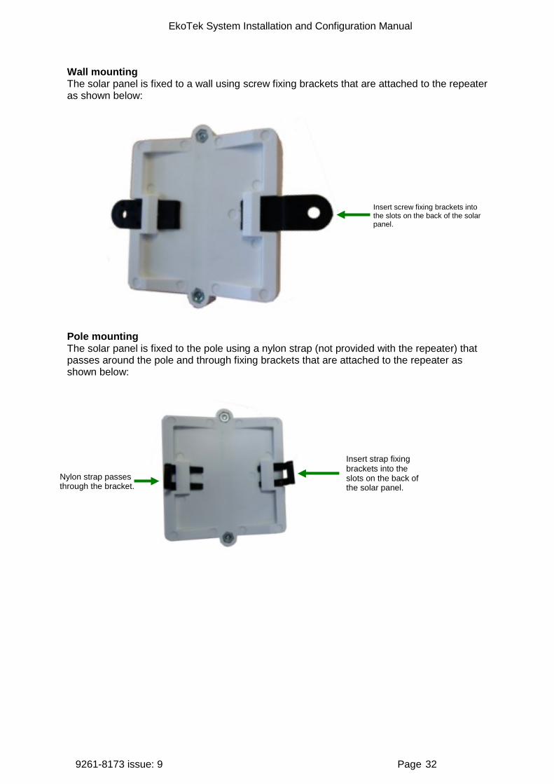
Wall mounting The solar panel is fixed to a wall using screw fixing brackets that are attached to the repeater as shown below:
Pole mounting The solar panel is fixed to the pole using a nylon strap (not provided with the repeater) that passes around the pole and through fixing brackets that are attached to the repeater as shown below:
Insert strap fixing brackets into the slots on the back of the solar panel.
Nylon strap passes through the bracket.
Insert screw fixing brackets into the slots on the back of the solar panel.
EkoTek System Installation and Configuration Manual
9261-8173 issue: 9 Page 33
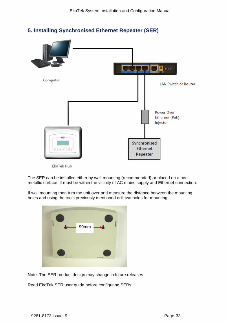
5. Installing Synchronised Ethernet Repeater (SER)
The SER can be installed either by wall-mounting (recommended) or placed on a non-metallic surface. It must be within the vicinity of AC mains supply and Ethernet connection.
If wall mounting then turn the unit over and measure the distance between the mounting holes and using the tools previously mentioned drill two holes for mounting.
Note: The SER product design may change in future releases.
Read EkoTek SER user guide before configuring SERs.
90mm
EkoTek System Installation and Configuration Manual
9261-8173 issue: 9 Page 34
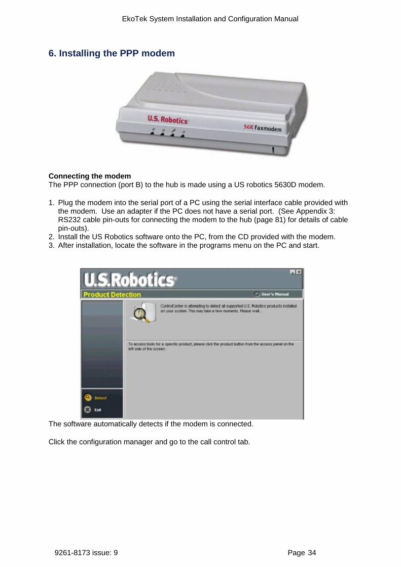
6. Installing the PPP modem
Connecting the modem The PPP connection (port B) to the hub is made using a US robotics 5630D modem.
1. Plug the modem into the serial port of a PC using the serial interface cable provided with the modem. Use an adapter if the PC does not have a serial port. (See Appendix 3: RS232 cable pin-outs for connecting the modem to the hub (page 81) for details of cable pin-outs).
2. Install the US Robotics software onto the PC, from the CD provided with the modem. 3. After installation, locate the software in the programs menu on the PC and start.
The software automatically detects if the modem is connected.
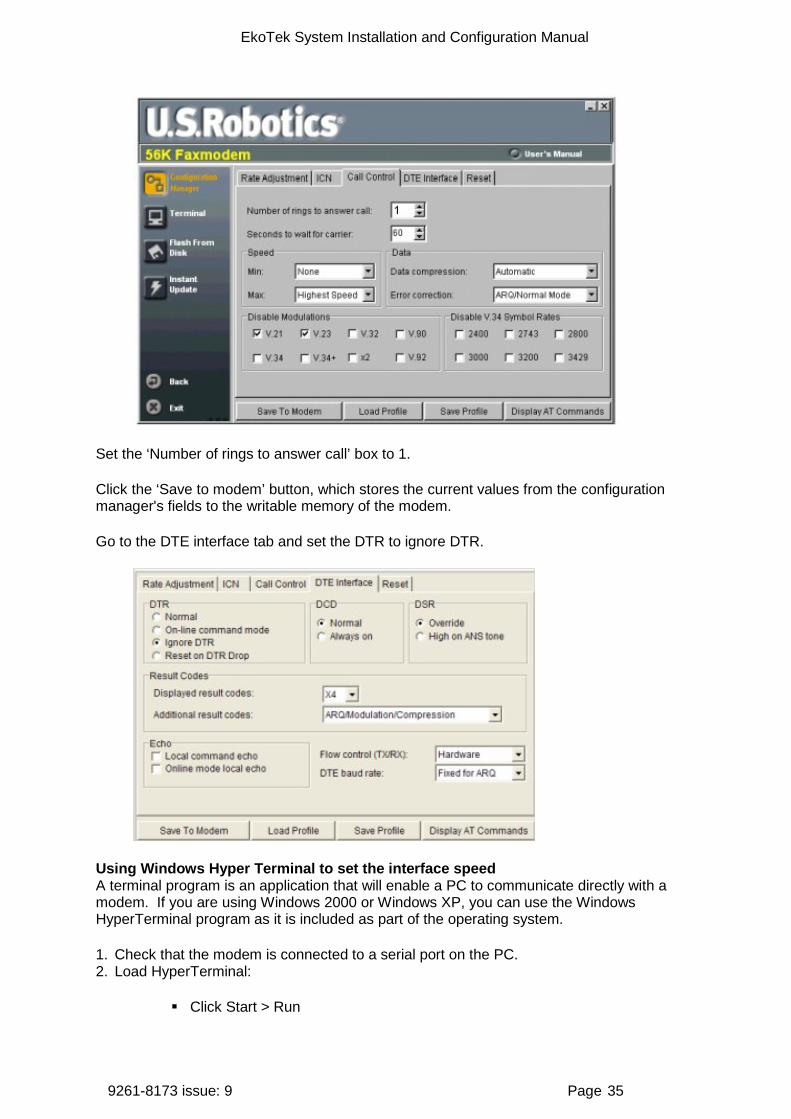
Click the configuration manager and go to the call control tab.
EkoTek System Installation and Configuration Manual
9261-8173 issue: 9 Page 35
Set the ‘Number of rings to answer call’ box to 1.
Click the ‘Save to modem’ button, which stores the current values from the configuration manager's fields to the writable memory of the modem.
Go to the DTE interface tab and set the DTR to ignore DTR.
Using Windows Hyper Terminal to set the interface speed A terminal program is an application that will enable a PC to communicate directly with a modem. If you are using Windows 2000 or Windows XP, you can use the Windows HyperTerminal program as it is included as part of the operating system.
1. Check that the modem is connected to a serial port on the PC. 2. Load HyperTerminal:
Click Start > Run

EkoTek System Installation and Configuration Manual
9261-8173 issue: 9 Page 36
In the box which appears, type HYPERTRM Click OK
If you see the error message 'Cannot find HYPERTRM' you will need to install HyperTerminal:
Click Start > Settings > Control Panel > Add / Remove Programs. In Add / Remove Programs select Properties and then click the Windows
Setup tab Double-click Communications Check the box for HyperTerminal Click OK, and then OK again to install Note: You may be asked for your Windows installation disk for this procedure
3. When Hyper Terminal starts you will be presented with a 'Connection description' dialogue box.
Click 'Cancel' to continue
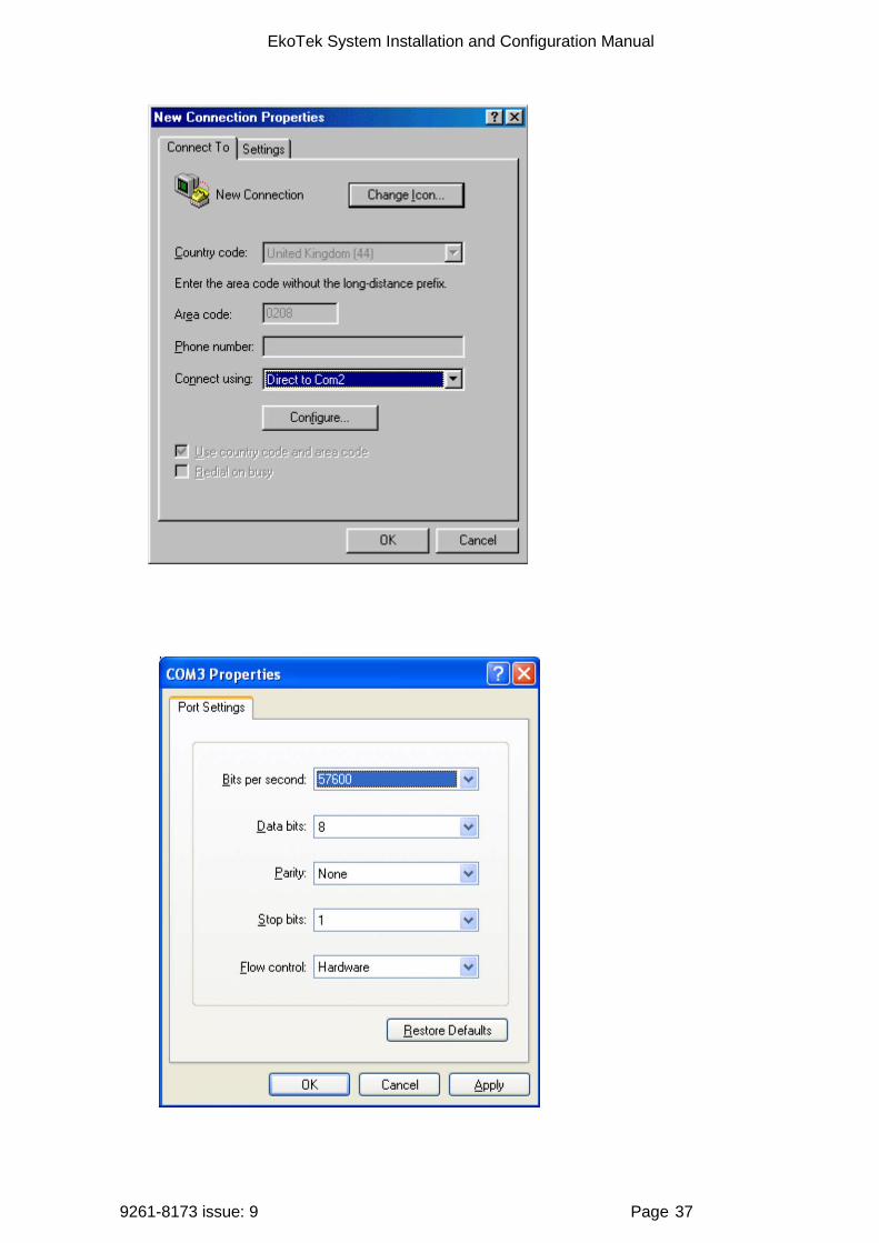
4. Select the preferred COM port:
Select 'File' then 'Properties' from the menu bar and the 'New connection properties' window will open
Click on the arrow for the 'Connect using' drop down box Select 'Direct to ComX' (where X is the COM port you are using to connect
the modem - e.g. COM1, or COM5, etc) Click OK
EkoTek System Installation and Configuration Manual
9261-8173 issue: 9 Page 37
EkoTek System Installation and Configuration Manual
9261-8173 issue: 9 Page 38
Configure the port to set the interface speed to 57600
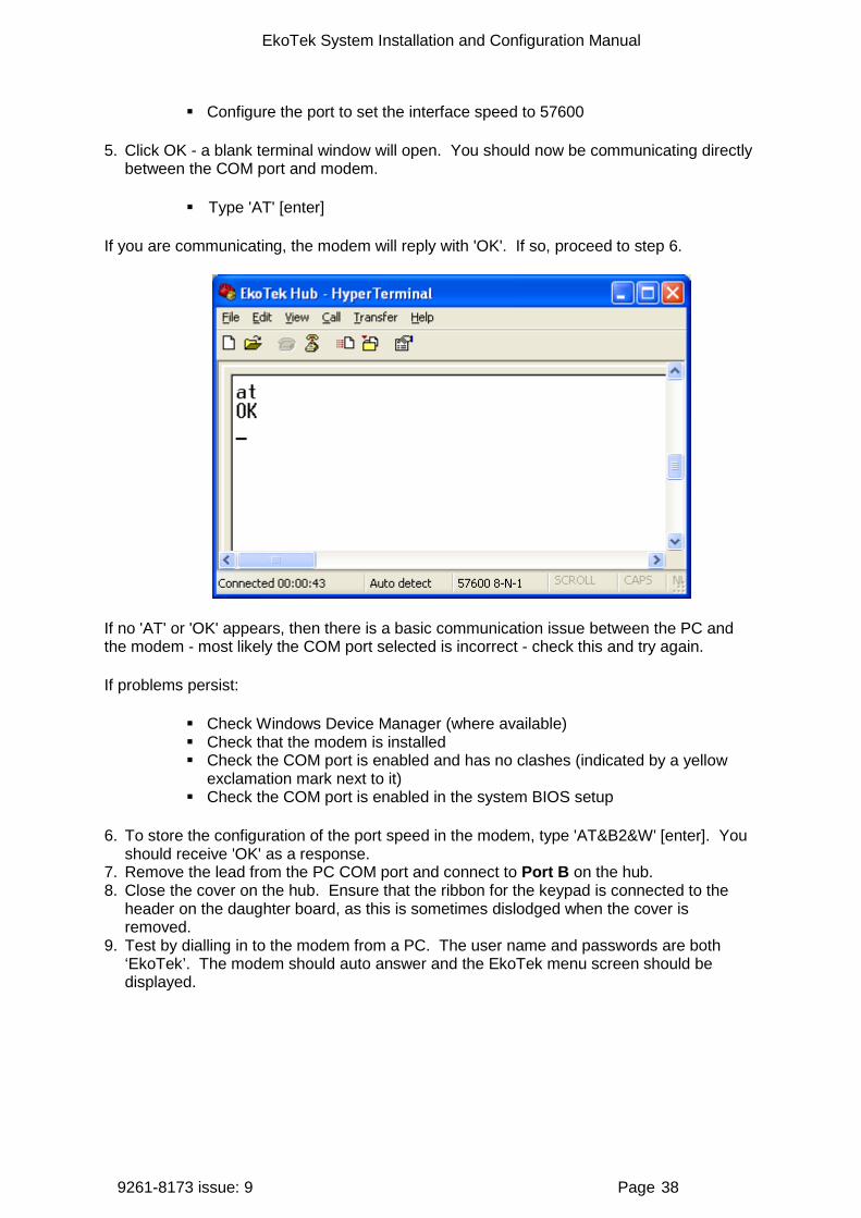
5. Click OK - a blank terminal window will open. You should now be communicating directly between the COM port and modem.
Type 'AT' [enter]
If you are communicating, the modem will reply with 'OK'. If so, proceed to step 6.
If no 'AT' or 'OK' appears, then there is a basic communication issue between the PC and the modem - most likely the COM port selected is incorrect - check this and try again.
If problems persist:
Check Windows Device Manager (where available) Check that the modem is installed Check the COM port is enabled and has no clashes (indicated by a yellow
exclamation mark next to it) Check the COM port is enabled in the system BIOS setup
6. To store the configuration of the port speed in the modem, type 'AT&B2&W' [enter]. You should receive 'OK' as a response.
7. Remove the lead from the PC COM port and connect to Port B on the hub. 8. Close the cover on the hub. Ensure that the ribbon for the keypad is connected to the
header on the daughter board, as this is sometimes dislodged when the cover is removed.
9. Test by dialling in to the modem from a PC. The user name and passwords are both ‘EkoTek’. The modem should auto answer and the EkoTek menu screen should be displayed.

EkoTek System Installation and Configuration Manual
9261-8173 issue: 9 Page 39
Set up system configuration using the browser as described in the ‘
8. Browser interface section’.

EkoTek System Installation and Configuration Manual
9261-8173 issue: 9 Page 40
7. Installing the four-way pager charging rack
Up to 2 four-way charging racks may be supplied from the PSU.
Wall mounting the four-way charging racks Measure and drill the wall according to the diagram
If two units are used, join together using the nylon screws and nuts provided as shown below:
Warning label Fix the warning label close to the rack where it is easily visible.
RECHARGEABLE
CELLS ONLY
Wall mounting the assist multi-way charger units
Up to 8 multi-way charging racks may be supplied from the PSU.
Measure and drill the wall according to the screw holes in the back of the multi-way chargers.
The PSU adaptor can also be wall mounted. Fix the bracket to the wall and attach the adaptor using the supplied cable tie.

EkoTek System Installation and Configuration Manual
9261-8173 issue: 9 Page 41
IDC connections Remove or cut off the power jack from the end of the PSU lead. Bare the ends and connect to the IDC connector in the first rack. Ensure the polarity is correct, (+ve black with the white stripe) as shown in the diagram above. Loop the supply through to the second rack if fitted, and terminate as shown in the diagram below.
+ +
- -21
21
+ve Black/White -ve Black
8. Browser interface setup
Initial setup In order to configure the system a PC or a network Ethernet connection needs to be made to the hub. This connection can also be used to monitor the EkoTek network. Once the connection has been made, then communication with the hub is achieved through a web browser.
Connecting the hub to the PC using Windows Ensure the isolator switch is turned on in order for the hub to power up.
On the PC:
1. Click the Windows start menu and select Control Panel. 2. Click ‘Network and Internet connections’. 3. Click ‘Network Connections’. With the network cable disconnected, the Local Area
connection will be shown as unplugged (X).
Port A - (DB9) Port B -
(DB9) Isolator Switch

EkoTek System Installation and Configuration Manual
9261-8173 issue: 9 Page 42
4. Open the hub. To open the hub, push the two locking tabs in and then separate the cover from the back plate.
5. Connect an Ethernet (RJ45) patch cable to the RJ45 connector - see the hub interfaces diagram.
6. Connect the other end of the patch cable to the Ethernet (RJ45) connector on the PC. Note: Some network cards require a crossover cable for direct connection.
7. If connected correctly the screen will change to show the cable connected.
8. Double click the ‘Local Area Connection’ icon to open the properties window.
9. Scroll the new window and select the ‘Internet Protocol TCP/IP’ menu item.
EkoTek System Installation and Configuration Manual
9261-8173 issue: 9 Page 43
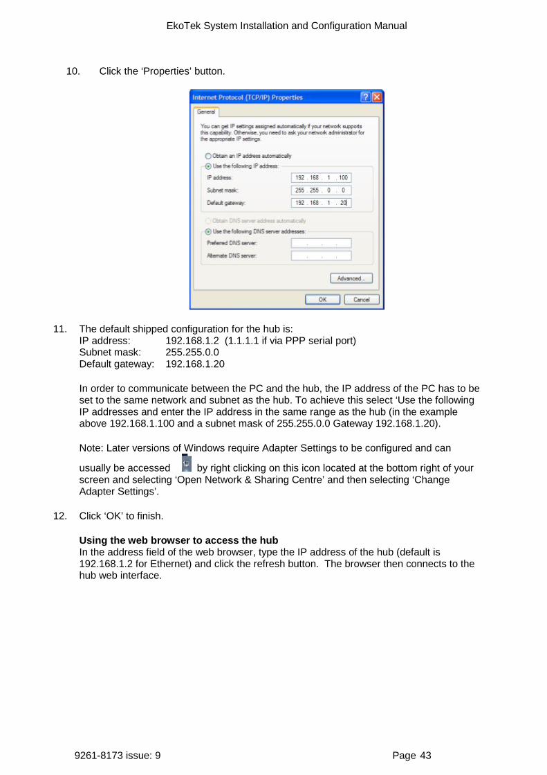
10. Click the ‘Properties’ button.
11. The default shipped configuration for the hub is: IP address: 192.168.1.2 (1.1.1.1 if via PPP serial port) Subnet mask: 255.255.0.0 Default gateway: 192.168.1.20
In order to communicate between the PC and the hub, the IP address of the PC has to be set to the same network and subnet as the hub. To achieve this select ‘Use the following IP addresses and enter the IP address in the same range as the hub (in the example above 192.168.1.100 and a subnet mask of 255.255.0.0 Gateway 192.168.1.20).
Note: Later versions of Windows require Adapter Settings to be configured and can
usually be accessed by right clicking on this icon located at the bottom right of your screen and selecting ‘Open Network & Sharing Centre’ and then selecting ‘Change Adapter Settings’.
12. Click ‘OK’ to finish.
Using the web browser to access the hub In the address field of the web browser, type the IP address of the hub (default is 192.168.1.2 for Ethernet) and click the refresh button. The browser then connects to the hub web interface.
EkoTek System Installation and Configuration Manual
9261-8173 issue: 9 Page 44
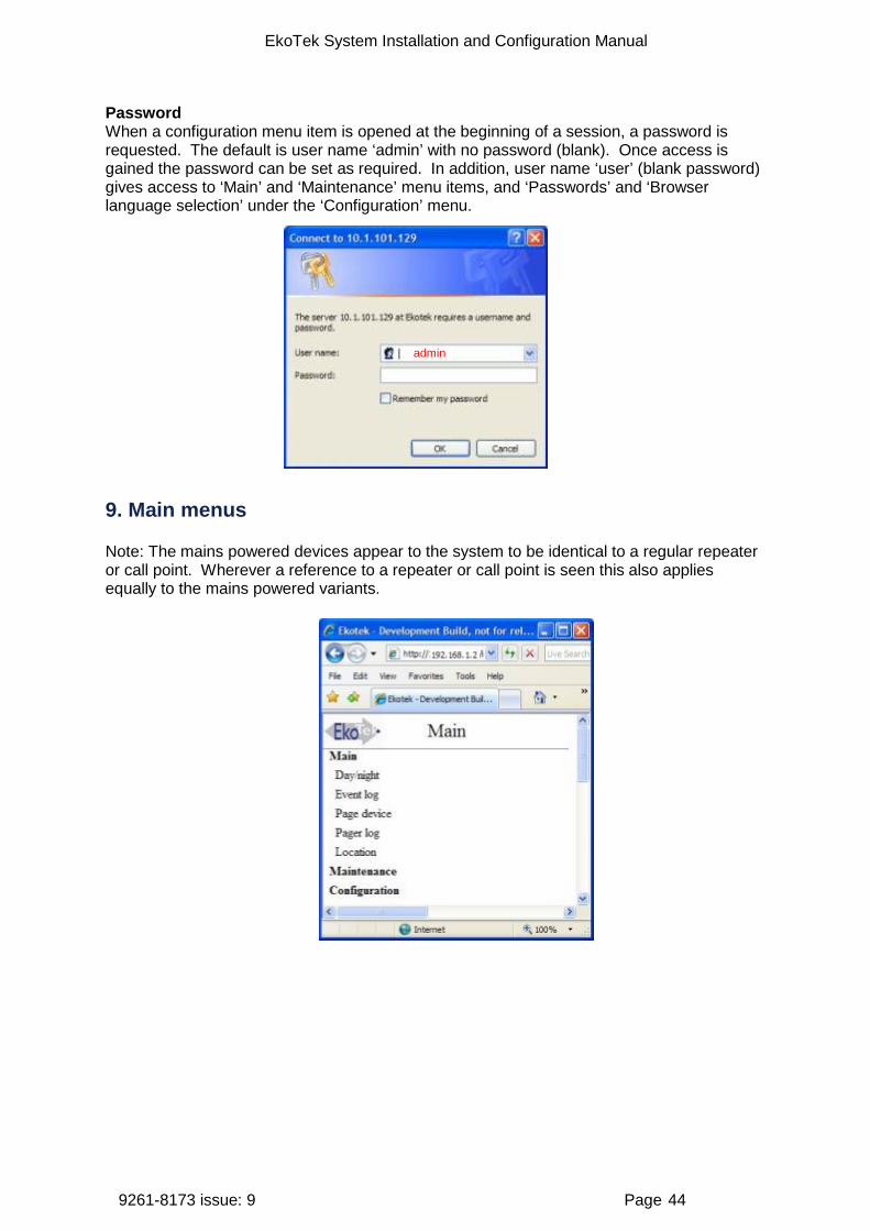
Password When a configuration menu item is opened at the beginning of a session, a password is requested. The default is user name ‘admin’ with no password (blank). Once access is gained the password can be set as required. In addition, user name ‘user’ (blank password) gives access to ‘Main’ and ‘Maintenance’ menu items, and ‘Passwords’ and ‘Browser language selection’ under the ‘Configuration’ menu.
9. Main menus
Note: The mains powered devices appear to the system to be identical to a regular repeater or call point. Wherever a reference to a repeater or call point is seen this also applies equally to the mains powered variants.
admin
EkoTek System Installation and Configuration Manual
9261-8173 issue: 9 Page 45
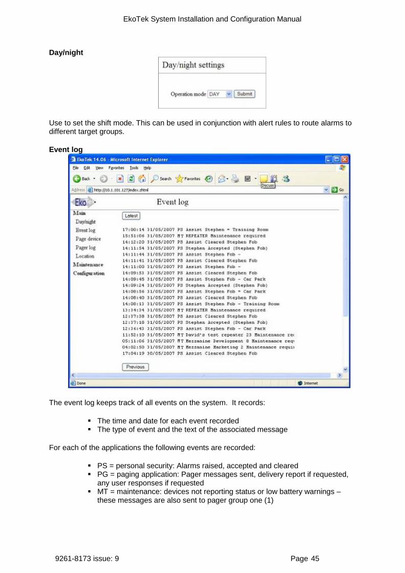
Day/night
Use to set the shift mode. This can be used in conjunction with alert rules to route alarms to different target groups.
Event log
The event log keeps track of all events on the system. It records:
The time and date for each event recorded The type of event and the text of the associated message
For each of the applications the following events are recorded:
PS = personal security: Alarms raised, accepted and cleared PG = paging application: Pager messages sent, delivery report if requested,
any user responses if requested MT = maintenance: devices not reporting status or low battery warnings –
these messages are also sent to pager group one (1)
EkoTek System Installation and Configuration Manual
9261-8173 issue: 9 Page 46
"Enter message here”
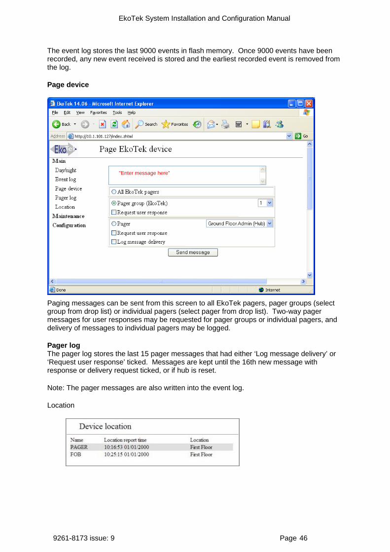
The event log stores the last 9000 events in flash memory. Once 9000 events have been recorded, any new event received is stored and the earliest recorded event is removed from the log.
Page device
Paging messages can be sent from this screen to all EkoTek pagers, pager groups (select group from drop list) or individual pagers (select pager from drop list). Two-way pager messages for user responses may be requested for pager groups or individual pagers, and delivery of messages to individual pagers may be logged.
Pager log The pager log stores the last 15 pager messages that had either ‘Log message delivery’ or ‘Request user response’ ticked. Messages are kept until the 16th new message with response or delivery request ticked, or if hub is reset.
Note: The pager messages are also written into the event log.
Location
EkoTek System Installation and Configuration Manual
9261-8173 issue: 9 Page 47
If location reporting for mobile devices has been enabled under the device mode, the location screen shows the last location reported by each mobile device.
If a device does not have location reporting enabled ‘Not enabled’ will appear in place of the location report time and location.
If a device has not reported its location since the hub has powered up it will display ‘Unknown’.
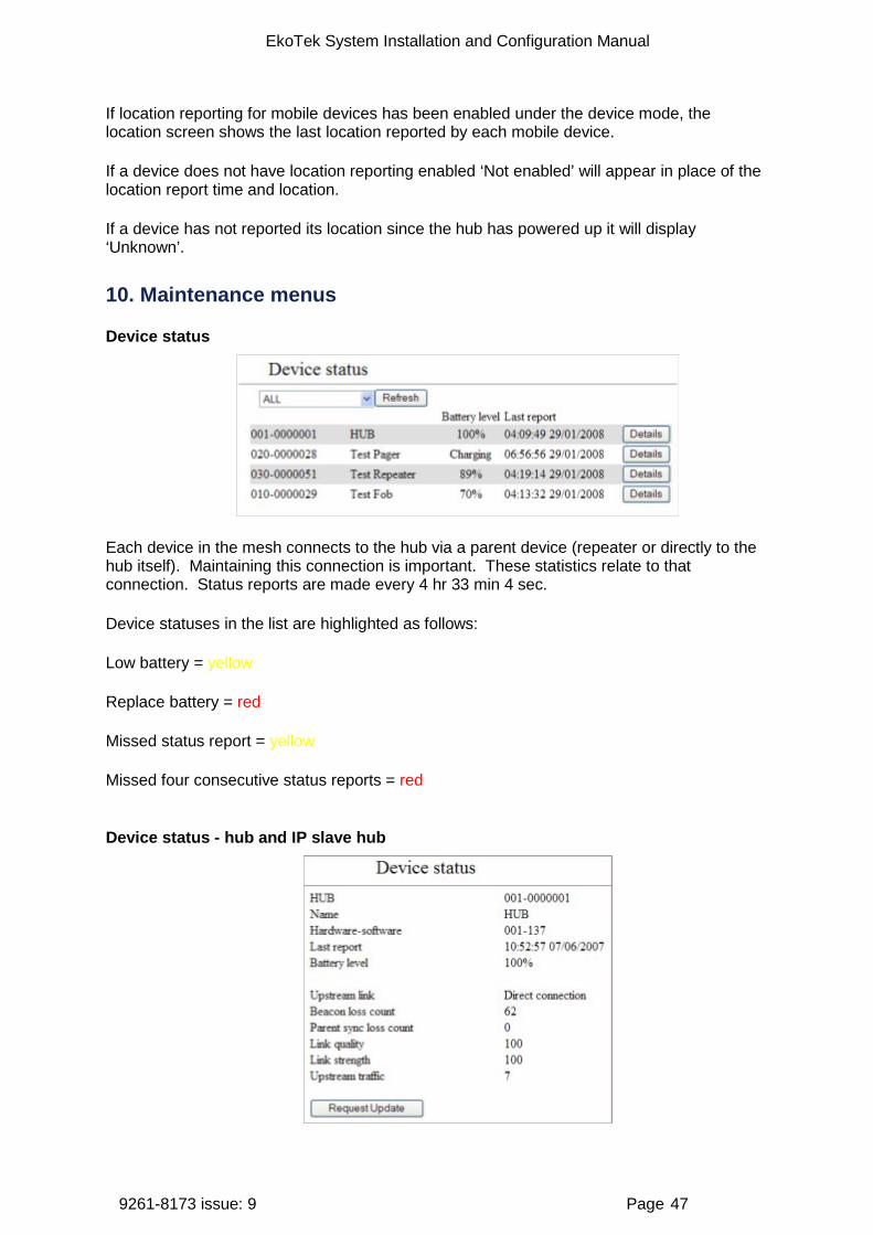
10. Maintenance menus
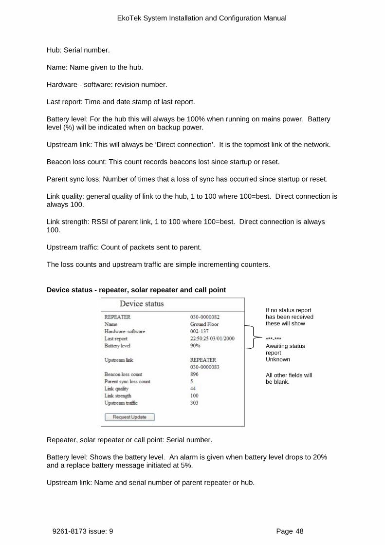
Device status
Each device in the mesh connects to the hub via a parent device (repeater or directly to the hub itself). Maintaining this connection is important. These statistics relate to that connection. Status reports are made every 4 hr 33 min 4 sec.
Device statuses in the list are highlighted as follows:
Low battery = yellow
Replace battery = red
Missed status report = yellow
Missed four consecutive status reports = red
Device status - hub and IP slave hub
EkoTek System Installation and Configuration Manual
9261-8173 issue: 9 Page 48
Hub: Serial number.
Name: Name given to the hub.
Hardware - software: revision number.
Last report: Time and date stamp of last report.
Battery level: For the hub this will always be 100% when running on mains power. Battery level (%) will be indicated when on backup power.
Upstream link: This will always be ‘Direct connection’. It is the topmost link of the network.
Beacon loss count: This count records beacons lost since startup or reset.
Parent sync loss: Number of times that a loss of sync has occurred since startup or reset.
Link quality: general quality of link to the hub, 1 to 100 where 100=best. Direct connection is always 100.
Link strength: RSSI of parent link, 1 to 100 where 100=best. Direct connection is always 100.
Upstream traffic: Count of packets sent to parent.
The loss counts and upstream traffic are simple incrementing counters.
Device status - repeater, solar repeater and call point
Repeater, solar repeater or call point: Serial number.
Battery level: Shows the battery level. An alarm is given when battery level drops to 20% and a replace battery message initiated at 5%.
Upstream link: Name and serial number of parent repeater or hub.
If no status report has been received these will show
***-*** Awaiting status report Unknown
All other fields will be blank.

EkoTek System Installation and Configuration Manual
9261-8173 issue: 9 Page 49
Beacon loss count: Missed parent beacons. This counts the number of times the beacon was expected but not received, either through a faulty parent or degradation of the signal to the parent.
Parent sync loss: Number of times that a loss of sync with parent has occurred.
Other fields are the same as for the hub.
Device status - call fob and pager
Pager or fob: Serial number.
Name: Name given to device.
Hardware - software: revision number.
Last report: Time and date stamp of last report.
Battery level: Shows the battery level (%) or ‘Charging’ if the battery is being charged.
Beacon loss count: Missed parent beacons. This counts the number of times the call fob or pager has lost contact with its parent either, through faulty parent or degradation of the signal through moving out of range of the repeaters.
Parent sync loss: number of times that a loss of sync with parent has occurred.
Request update: Click to retrieve current statistics.
EkoTek System Installation and Configuration Manual
9261-8173 issue: 9 Page 50
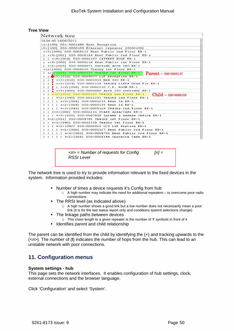
Tree View
The network tree is used to try to provide information relevant to the fixed devices in the system. Information provided includes:
Number of times a device requests it’s Config from hub o A high number may indicate the need for additional repeaters – to overcome poor radio
connections The RRSI level (as indicated above)
o A high number shows a good link but a low number does not necessarily mean a poor link (it is for the last status report only and conditions /parent selections change)
The linkage paths between devices o This chain length to a given repeater is the number of ‘I’ symbols in front of it
Identifies parent and child relationship
The parent can be identified from the child by identifying the (+) and tracking upwards to the (<n>). The number of (I) indicates the number of hops from the hub. This can lead to an unstable network with poor connections.
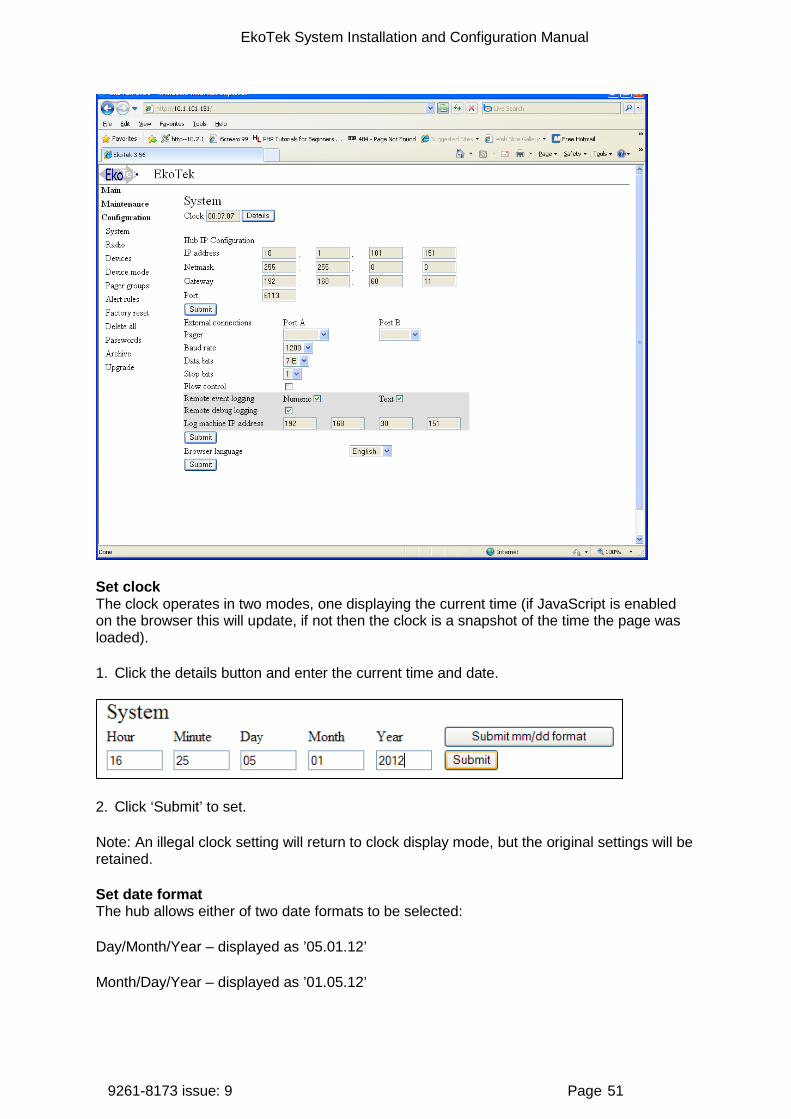
11. Configuration menus
System settings - hub This page sets the network interfaces. It enables configuration of hub settings, clock, external connections and the browser language.
Click ‘Configuration’ and select ‘System’.
Parent – 030-0005137
Child – 030-0005103
<n> = Number of requests for Config [n] = RSSI Level
EkoTek System Installation and Configuration Manual
9261-8173 issue: 9 Page 51
Set clock The clock operates in two modes, one displaying the current time (if JavaScript is enabled on the browser this will update, if not then the clock is a snapshot of the time the page was loaded).
1. Click the details button and enter the current time and date.
2. Click ‘Submit’ to set.
Note: An illegal clock setting will return to clock display mode, but the original settings will be retained.
Set date format The hub allows either of two date formats to be selected:
Day/Month/Year – displayed as ’05.01.12’
Month/Day/Year – displayed as ’01.05.12’
EkoTek System Installation and Configuration Manual
9261-8173 issue: 9 Page 52
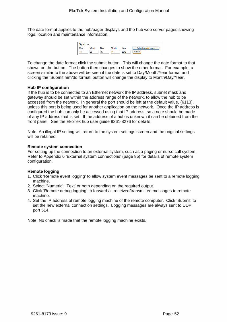
The date format applies to the hub/pager displays and the hub web server pages showing logs, location and maintenance information.
To change the date format click the submit button. This will change the date format to that shown on the button. The button then changes to show the other format. For example, a screen similar to the above will be seen if the date is set to Day/Month/Year format and clicking the ‘Submit mm/dd format’ button will change the display to Month/Day/Year.
Hub IP configuration If the hub is to be connected to an Ethernet network the IP address, subnet mask and gateway should be set within the address range of the network, to allow the hub to be accessed from the network. In general the port should be left at the default value, (6113), unless this port is being used for another application on the network. Once the IP address is configured the hub can only be accessed using that IP address, so a note should be made of any IP address that is set. If the address of a hub is unknown it can be obtained from the front panel. See the EkoTek hub user guide 9261-8276 for details.
Note: An illegal IP setting will return to the system settings screen and the original settings will be retained.
Remote system connection For setting up the connection to an external system, such as a paging or nurse call system. Refer to Appendix 6 ‘External system connections’ (page 85) for details of remote system configuration.
Remote logging 1. Click ‘Remote event logging’ to allow system event messages be sent to a remote logging
machine. 2. Select ‘Numeric’, ‘Text’ or both depending on the required output. 3. Click ‘Remote debug logging’ to forward all received/transmitted messages to remote
machine. 4. Set the IP address of remote logging machine of the remote computer. Click ‘Submit’ to
set the new external connection settings. Logging messages are always sent to UDP port 514.
Note: No check is made that the remote logging machine exists.
EkoTek System Installation and Configuration Manual
9261-8173 issue: 9 Page 53
For more details of the event logging protocol see Appendix 4B: Channel allocation with SER
1. Overview
The SERs is used in a customer network to provide synchronised radio coverage over a larger site without having to resort to separate or overlapping systems. The repeater operates in a similar way to a normal repeater except for the fact it is linked back to the hub via the customer’s LAN. Each SER is allocated its own channels to operate in its own area and link with the other repeaters in its vicinity, because it is linked back via the LAN it does not need to be able to reach back to the hub via the radio path.
This helps to reduce long chains of repeaters across a larger site and means set channels can be used in different areas of a large site. This helps to ensure a stable radio network. Linking between buildings can be done using SERs via LAN where before a ‘chain of repeaters’ would have been required (this helps by reducing the overall device count on the system).
With complex network setups advice should always be sought from Multitone Customer Services for assistance when planning this type of installation.
Appendix 5: Remote logging protocol (page 85).
Language The browser interface is available in multiple language variants and it is therefore important to ensure you have the correct version installed for your customer. Select the required language from the drop list and click ‘Submit’.
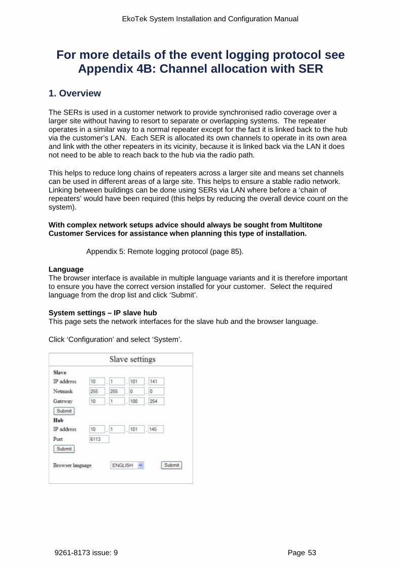
System settings – IP slave hub This page sets the network interfaces for the slave hub and the browser language.
Click ‘Configuration’ and select ‘System’.
EkoTek System Installation and Configuration Manual
9261-8173 issue: 9 Page 54
Slave The IP address, subnet mask and gateway should be set within the address range of the network, to allow the hub to be accessed from the network. Once the IP address is configured, then the slave hub can only be accessed using that IP address, so a note should be made of any IP address that is set. If the address of a hub is unknown it can be obtained from the front panel.
Click ‘Submit’ to save the slave hub settings.
Hub IP address: Enter the IP address of the main system hub.
Port: Set the port to that set in the system settings for the main hub.
Click ‘Submit’ to save the main hub settings.
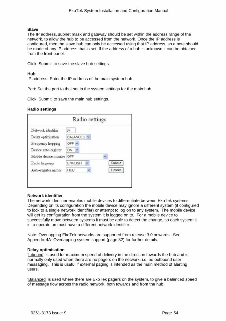
Radio settings
Network identifier The network identifier enables mobile devices to differentiate between EkoTek systems. Depending on its configuration the mobile device may ignore a different system (if configured to lock to a single network identifier) or attempt to log on to any system. The mobile device will get its configuration from the system it is logged on to. For a mobile device to successfully move between systems it must be able to detect the change, so each system it is to operate on must have a different network identifier.
Note: Overlapping EkoTek networks are supported from release 3.0 onwards. See Appendix 4A: Overlapping system support (page 82) for further details.
Delay optimisation ‘Inbound’ is used for maximum speed of delivery in the direction towards the hub and is normally only used when there are no pagers on the network, i.e. no outbound user messaging. This is useful if external paging is intended as the main method of alerting users.
‘Balanced’ is used where there are EkoTek pagers on the system, to give a balanced speed of message flow across the radio network, both towards and from the hub.
EkoTek System Installation and Configuration Manual
9261-8173 issue: 9 Page 55
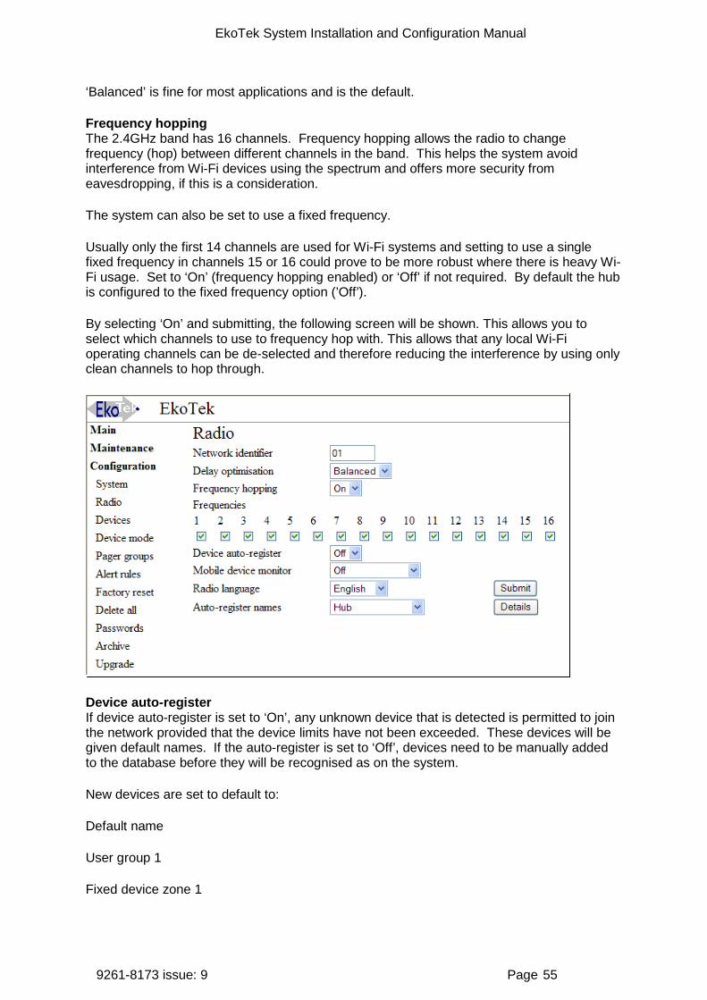
‘Balanced’ is fine for most applications and is the default.
Frequency hopping The 2.4GHz band has 16 channels. Frequency hopping allows the radio to change frequency (hop) between different channels in the band. This helps the system avoid interference from Wi-Fi devices using the spectrum and offers more security from eavesdropping, if this is a consideration.
The system can also be set to use a fixed frequency.
Usually only the first 14 channels are used for Wi-Fi systems and setting to use a single fixed frequency in channels 15 or 16 could prove to be more robust where there is heavy Wi-Fi usage. Set to ‘On’ (frequency hopping enabled) or ‘Off’ if not required. By default the hub is configured to the fixed frequency option (’Off’).
By selecting ‘On’ and submitting, the following screen will be shown. This allows you to select which channels to use to frequency hop with. This allows that any local Wi-Fi operating channels can be de-selected and therefore reducing the interference by using only clean channels to hop through.
Device auto-register If device auto-register is set to ‘On’, any unknown device that is detected is permitted to join the network provided that the device limits have not been exceeded. These devices will be given default names. If the auto-register is set to ‘Off’, devices need to be manually added to the database before they will be recognised as on the system.
New devices are set to default to:
Default name
User group 1
Fixed device zone 1

EkoTek System Installation and Configuration Manual
9261-8173 issue: 9 Page 56
Device mode 1
Any devices with a display will be added to the first pager group if capacity exists.
Mobile device monitor All fixed devices are automatically monitored for battery condition and presence on the network, with maintenance messages generated on low battery or absence of the device from the network; these messages are sent to all users in pager group 1. Mobile devices (pagers and call fobs) can also be monitored for battery condition and presence on the network. Set to ‘Off’, ‘Battery’ or ‘Network+Battery’ as required.
Note: The battery condition will be displayed on the ‘Device status’ page, regardless of this setting.
Radio language The pager display language is available in English, Francais, Espanol, Deutsch, Svenska or Norsk. Select required language from the drop list and click ‘Submit’.
Auto-register names With the device auto-register set to ‘On’, when the network detects a device it gives a default name appropriate to the device type: HUB, IP SLAVE, REPEATER, SOLAR REPEATER, CALL POINT, PAGER or FOB. This default name can be redefined if required.
Select device from the drop list and click ‘Details’. Enter a new name for the default and click ‘Submit’ to set. For example, this sequence could be used to set all pagers to register by default as ‘Staff’ and all call fobs as ‘Visitor’.
Devices
The devices page lists ALL the devices connected in the EkoTek network when ALL is selected.
Refresh To get the current list of devices, select the hardware type to be listed from the drop list and click the ‘Refresh’ button.
The devices will then be listed;
1. The first column gives the hardware type and serial number of the device.

EkoTek System Installation and Configuration Manual
9261-8173 issue: 9 Page 57
2. The second column gives the device name. 3. The third provides a ’Details ‘- button, to go to that specific device’s record.
The serial number of each device is displayed and the device name.
001-xxxxxxx indicates a hub.
002-xxxxxxx indicates a IP slave hub
004-xxxxxxx indicates an Ethernet Repeater
010-xxxxxxx indicates a call fob
020-xxxxxxx indicates a pager
030-xxxxxxx indicates a repeater
031-xxxxxxx indicates a solar repeater
040-xxxxxxx indicates a call point
Click the ‘Details’ button to see the device configuration.
Add Click ‘Add’ at the bottom of the displayed list to go to the ‘Select device’ new entry pages.
1. Select device type from menu. 2. Enter serial box and enter the serial number and name. The entry screen below is for a
repeater. Similar screens are shown for other device types, with the appropriate hardware code displayed.
3. Click ‘Add’ to add the new device. If the entry is valid the individual device entry page will then be displayed. If entry is not possible (invalid serial number length, attempt to add a device prior to the hub, attempt to add a second hub, too many devices already on-system, etc.) then ‘Invalid device request’ will be displayed. If a device exists in the database with the same serial number as the new requested device, the existing device details will be displayed.
Details Hub, IP slave hub and call point

EkoTek System Installation and Configuration Manual
9261-8173 issue: 9 Page 58
Name The name of the hub or call point may be changed, by entering a new name in the box.
Device mode The hub or call point is allocated a device mode (1-32), with 1 as default. However, the name for each device mode can be user configured, in which case different options will appear in this menu. The device mode defines the behaviours of all similar devices (radio channel, alarm raising ability, etc). See the ‘Device mode’ section (page60).
User group Select from the drop list, to set ‘User Group’ (1-16). Used to route alarms to different pager groups.
Zone Fixed devices are allocated a zone number, allowing alarms from mobile devices to be sent to different pager groups based on the hub or repeater (and therefore zone) that the mobile device is connected to, and for directly raising location alarms. Up to 16 zones are supported by the EkoTek system.
After selecting the device mode parameters, click ‘Submit’ to enter the changes.
Repeater and solar repeater
Name The name of the repeater may be changed, by entering a new name in the box.
Device mode Each repeater is allocated a device mode (1-32), with 1 as default. However, the name for each device mode can be user configured, in which case different options will appear in this
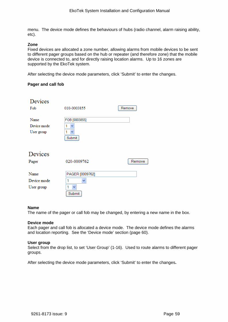
EkoTek System Installation and Configuration Manual
9261-8173 issue: 9 Page 59
menu. The device mode defines the behaviours of hubs (radio channel, alarm raising ability, etc).
Zone Fixed devices are allocated a zone number, allowing alarms from mobile devices to be sent to different pager groups based on the hub or repeater (and therefore zone) that the mobile device is connected to, and for directly raising location alarms. Up to 16 zones are supported by the EkoTek system.
After selecting the device mode parameters, click ‘Submit’ to enter the changes.
Pager and call fob
Name The name of the pager or call fob may be changed, by entering a new name in the box.
Device mode Each pager and call fob is allocated a device mode. The device mode defines the alarms and location reporting. See the ‘Device mode’ section (page 60).
User group Select from the drop list, to set ‘User Group’ (1-16). Used to route alarms to different pager groups.
After selecting the device mode parameters, click ‘Submit’ to enter the changes.

EkoTek System Installation and Configuration Manual
9261-8173 issue: 9 Page 60
Device mode
This section allows changes to be made to device parameters. The initial page presents a list of the different hardware types. A drop down menu allows selection of a specific device mode for the hardware type (by default these are 1-32, but they can be renamed) and a ‘Details’ button, which goes to the specific hardware device mode page.
Device mode – hub and IP slave hub
The hardware type is followed by the modifiable device mode name (default is 1-32).
Channel Select from the drop down menu (1 -> 16) to set the radio channel to be used by the hub. The default value of 15 should be used where possible. Different channels should be used for each hub when installing overlapping systems. Channel 15 should not be used by any overlapping system – as this can interfere with location reporting of the other overlapped systems.
See Appendix 4A: Overlapping system support (page 82).
Location range Defines the range of the location signal from the hub. The default value is ‘2’ which gives an approximate range in indoor environments of 3 metres. A value of ‘1’ gives the shortest
EkoTek System Installation and Configuration Manual
9261-8173 issue: 9 Page 61
range and ‘10’ the longest range. The range should not be set to high values in deployments where location signal penetration through walls and floors is not desired.
Manual alarm enable Sets whether the hub can raise manual alarms, i.e. by pressing the button.
Alert text Modify text to define the message sent to pagers when the alarm is activated. The default text is ‘Assist’.
Operation Define how many button presses are required to trigger the manual alarm (1 or 2) selected by drop-down menu. Select either ‘Single click’ or ‘Double click’.
Alarm audible alert Define whether device buzzer sounds when manual alarm is raised.
Dead man alarm enabled Enable the dead man automatic alarm. This is raised if no input is received from the user when prompted by the device.
Assist alarm enabled Enable the assist alarm. This is raised using the blue button on the Assist pager and fob.
Alert text Modify text to define the message sent to pagers when this alarm is activated. The default text is ‘No response’.
Timer interval Sets the time (minutes) between user input prompts.
User alert period Sets the length of time (seconds) that the buzzer sounds on the hub after the user input prompt before the alarm is raised. If the user presses a button during this time the alarm is not raised.
Alarm clearance alert text Modifiable text appears in the message sent to pagers when any alarm for this device is cleared. The default text is ‘Cleared’.
Alarm escalation period If an active alarm is not cleared within this period of time (minutes), then the device resends the alarm with an alternate escalation level.
After selecting the above parameters, click ‘Submit’ to enter the changes.

EkoTek System Installation and Configuration Manual
9261-8173 issue: 9 Page 62
Device mode – repeater and solar repeater
The device mode entry page shows the hardware type, followed by the modifiable device mode name (defaults 1-32).
Lock to network With Overlapping System Support (OSS), the repeaters must be locked to a network if there are overlapping systems. To lock to a network check the ‘Lock to network’ box. It is advised that ‘Lock to network’ should not be checked for single standalone systems, and should not be checked for an overlapping system until all devices have joined the network. For more details see Appendix 4A: Overlapping system support (page 78).
Upstream channel/downstream channel This applies to repeaters, solar repeaters and call points only. It is used to determine the radio channel (1-16) of the repeater, selected via drop down menu. In addition, the ‘As parent’ setting allows a repeater to use the same radio channel as its parent device. This is the default setting but should be set to match ‘local’ site network requirements, allowing for a self-organising radio network.
Location range Defines the range of the location signal from the repeater. The default value is ‘2’ which gives an approximate range in indoor environments of 3m. A value of ‘1’ gives the shortest range and ‘10’ the longest range. The range should not be set to high values in deployments where location signal penetration through walls and floors is not desired.
After selecting the above parameters, click ‘Submit’ to enter the changes.
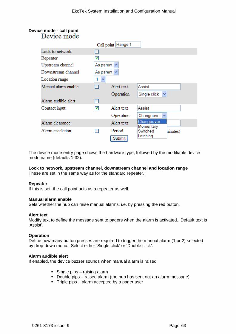
EkoTek System Installation and Configuration Manual
9261-8173 issue: 9 Page 63
Device mode - call point
The device mode entry page shows the hardware type, followed by the modifiable device mode name (defaults 1-32).
Lock to network, upstream channel, downstream channel and location range These are set in the same way as for the standard repeater.
Repeater If this is set, the call point acts as a repeater as well.
Manual alarm enable Sets whether the hub can raise manual alarms, i.e. by pressing the red button.
Alert text Modify text to define the message sent to pagers when the alarm is activated. Default text is ‘Assist’.
Operation Define how many button presses are required to trigger the manual alarm (1 or 2) selected by drop-down menu. Select either ‘Single click’ or ‘Double click’.
Alarm audible alert If enabled, the device buzzer sounds when manual alarm is raised:
Single pips – raising alarm Double pips – raised alarm (the hub has sent out an alarm message) Triple pips – alarm accepted by a pager user

EkoTek System Installation and Configuration Manual
9261-8173 issue: 9 Page 64
Contact Input Alert text Modify text to define the message sent to pagers when the alarm is activated. The default is ‘Red button’.
Operation This sets the criteria for the operation of the alarm.
Changeover - pull cords that have a contact that changes state each time the cord is pulled
Momentary - a momentary change of state on the 'raise' line input will cause an alarm to be raised (e.g. contact open-closed-open, or closed-open-closed). A second momentary change of state on the line will cause the alarm to be cleared. The alarm can also be cleared using the clear line or a long red button press. Really intended for connection to devices that automatically raise and clear alarms
Switched - switch type input e.g. a thermostat Latched – a momentary change of state on the 'raise' line input will cause an
alarm to be raised (e.g. contact open-closed-open, or closed-open-closed). Any further change of state will have no action. The alarm must be explicitly cleared by the clear line or red button. Allows the call point to be used in nurse call or other situations where there is a risk of repeated switch activation (ie. a patient repeatedly pulling on an emergency pull cord)
Alarm escalation enabled If the ‘Alarm escalation enable’ option is not selected, the call point will raise the alarm only once and the audible alarm indication on the call point will cancel after 30 seconds.
This is useful for non-critical alarms where the hassle of clearing the alarm outweighs the benefits of repeating alarms with escalation.
When the audible alarm indication cancels after 30 seconds a ‘Cleared’ message is not sent.
When the audible alarm indication ends the alarm can be raised again.
Alarm escalation period If an active alarm is not cleared within this period of time (minutes), the device resends the alarm with an alternate escalation level.
Device mode - pager and call fob
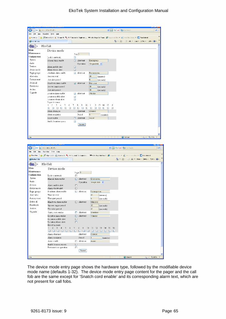
EkoTek System Installation and Configuration Manual
9261-8173 issue: 9 Page 65
The device mode entry page shows the hardware type, followed by the modifiable device mode name (defaults 1-32). The device mode entry page content for the pager and the call fob are the same except for ‘Snatch cord enable’ and its corresponding alarm text, which are not present for call fobs.
EkoTek System Installation and Configuration Manual
9261-8173 issue: 9 Page 66
Lock to network If the pager or call fob is to be used exclusively on a single network then the ‘Lock to network’ should be checked. See Appendix 4A: Overlapping system support (page 31).
Manual alarm enable Sets whether the pager or call fob can raise manual alarms, i.e. by pressing the button.
Alert Modify text to define the message sent to pagers when the alarm is activated. Defaults to ‘Assist’.
Operation Define how many button presses are required to trigger the manual alarm (1 or 2) selected by drop-down menu. Select either ‘Single click’ or ‘Double click’.
Alarm audible alert Define whether device buzzer sounds when manual alarm is raised.
Alarm vibrate alert Defines whether the vibrate motor is activated when a manual alarm is raised.
Dead man alarm enabled Enable the dead man automatic alarm. This is raised if no input is received from the user when prompted by the device.
Alert text Modify text to define the message sent to pagers when this alarm is activated. The default text is ‘No response’.
Timer interval Sets the time (minutes) between user input prompts being requested.
User alert period This feature sets the length of time (seconds) that the buzzer sounds on the hub after the user input prompt. If no entry from User then the alarm is raised, if the user presses a button during this time then the alarm is not raised.
Man down alarm enable Enable the tip-over switch automatic alarm. This is raised if the unit has been moved away from an upright position for a defined period of time.
Alert text Modifiable text appears in the message sent to pagers when this alarm is activated. Default text is ‘Man over’.
Tip-over trigger period Length of time a device must be moved away from upright, until the user warning buzzer sounds (seconds).
User alert period Length of time that the buzzer sounds on the device, without it being returned to the upright position and the cancel button pressed, before the alarm is raised (seconds).

EkoTek System Installation and Configuration Manual
9261-8173 issue: 9 Page 67
Snatch cord For pagers fitted with a snatch cord.
Snatch cord enabled When enabled, the user will raise an alarm whenever the snatch cord on a pager fitted with this device is removed. The alarm will be automatically cleared when the snatch cord is reattached.
Note: Where the blanking plug is used instead of the snatch cord, this feature should always be disabled.
Alert text Modifiable text appears in the message sent to pagers when this alarm is activated. Default text is ‘Snatched’.
Location alarm enabled Enable the location-based alarm. This is raised if the unit is moved to an area covered by repeaters assigned to an unauthorised zone. Check the box to enable this feature. Enter the text to be displayed when the alarm is triggered.
Location audible alert / vibrate alert The mobile device beeper and vibrate functions can be enabled or disabled when the alarm is raised, allowing either covert or normal alarm operation. Check boxes to enable alert.
Report in zones To select those zones where the alarm is to be raised, check the box associated with that zone. If the pager or call fob enters an unauthorised (checked) zone the location alarm will be raised. The location alarm will be cancelled automatically if the pager or call fob re-enters an authorised (unchecked) zone.
Alarm clearance alert text Modifiable text appears in the message sent to pagers when any alarm for this device is cleared. The default text is ‘Cleared’.
Alarm escalation period If an active alarm is not cleared within this period of time (minutes), then the device resends the alarm with an alternate escalation level.
Permanent on operation This disables the ability to turn off the device, providing permanent on operation.
Assist This enables the assist alert on both the fob and pager (blue button).
After selecting the above parameters, click ‘Submit’ to enter the changes.
Pager groups These pages are used to manage hubs and display pagers into groups. Devices may appear in none, one or many pager groups. Each group is restricted to 35 devices.
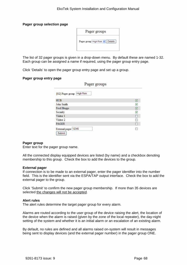
EkoTek System Installation and Configuration Manual
9261-8173 issue: 9 Page 68
Pager group selection page
The list of 32 pager groups is given in a drop-down menu. By default these are named 1-32. Each group can be assigned a name if required, using the pager group entry page.
Click ‘Details’ to open the pager group entry page and set up a group.
Pager group entry page
Pager group Enter text for the pager group name.
All the connected display equipped devices are listed (by name) and a checkbox denoting membership to this group. Check the box to add the devices to the group.
External pager If connection is to be made to an external pager, enter the pager identifier into the number field. This is the identifier sent via the ESPA/TAP output interface. Check the box to add the external pager to the group.
Click ‘Submit’ to confirm the new pager group membership. If more than 35 devices are selected the changes will not be accepted.
Alert rules The alert rules determine the target pager group for every alarm.
Alarms are routed according to the user group of the device raising the alert, the location of the device when the alarm is raised (given by the zone of the local repeater), the day-night setting of the system and whether it is an initial alarm or an escalation of an existing alarm.
By default, no rules are defined and all alarms raised on-system will result in messages being sent to display devices (and the external pager number) in the pager group ONE.

EkoTek System Installation and Configuration Manual
9261-8173 issue: 9 Page 69
The page operates in a number of modes, displaying the current rules table, allowing new rules to be added and existing rules to be modified and deleted. Creating alert rules ensures the right device is called at the right time instead of only sending everything to PG.1.
If any rules have been entered a table is displayed, the top row of which contains:
User group Parameters set in the device entry. Groups 1 to 16.
Zone Parameters set in the device entry. Zones 1 to 16.
Time The day or night setting of the system. ‘D’=day, ‘N’=night.
Esc The escalation level of the alarm. ‘R’=raised, ‘N’=normal.
A black square means that a particular group, zone, time of day or escalation has been included in the rule. The end of the row is a button containing the name of the pager group that is targeted by the rule. If there are more than 16 rules in the table, the header will be repeated after the last rule.
Edit mapping Clicking the pager group name button at the end of the row causes the page to be reloaded with modifiable rules; the selected rule will appear as a shaded row and in place of the pager group name a ‘Remove’ button will appear. The checkboxes are preloaded with the current rules settings. Change the rule settings as required and then click ‘Submit’ to save the amendments.
Note: the EkoTek system can only send one paging message to an external system as a result of an alarm being raised. If a combination of rules is entered that would cause more than one message to be sent to an external system a conflict is detected and the ‘Submit’ entry will be ignored until the conflict is resolved.
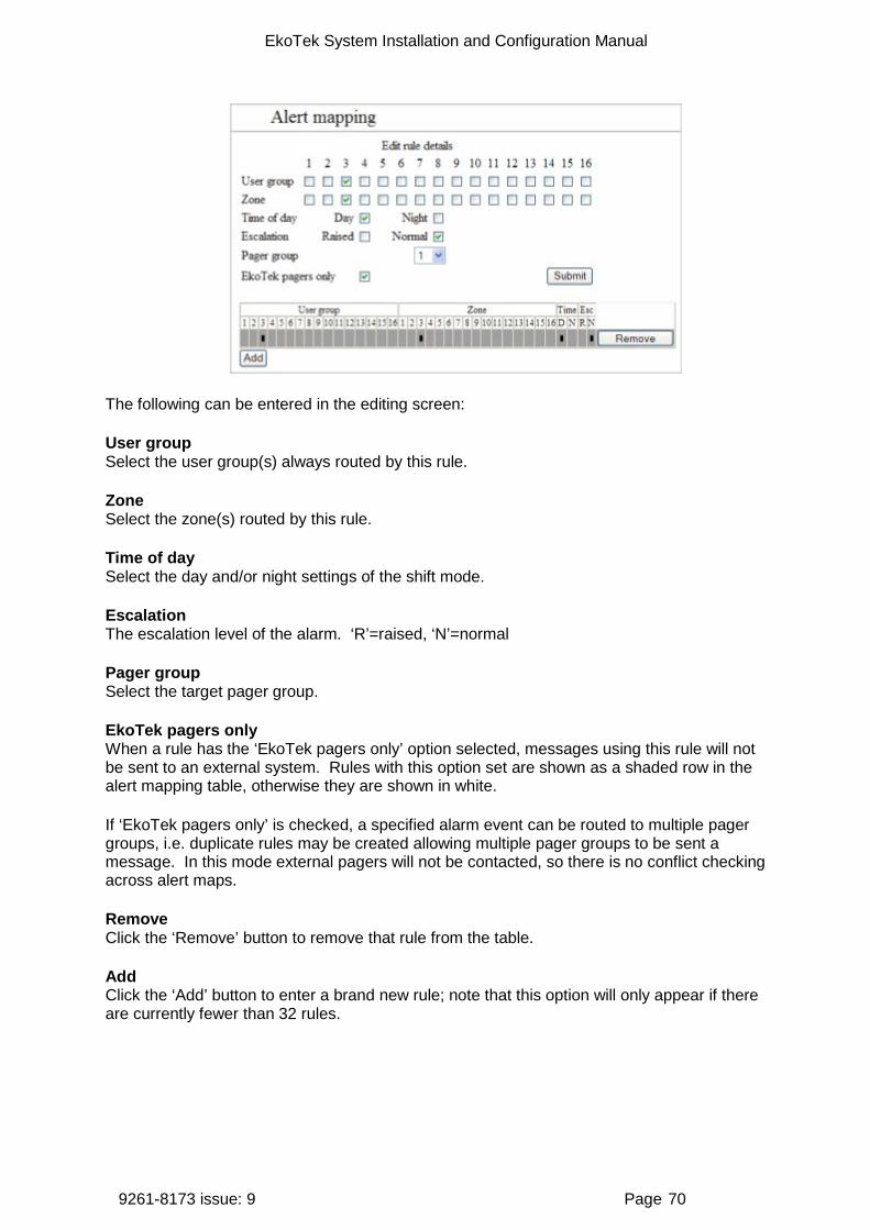
EkoTek System Installation and Configuration Manual
9261-8173 issue: 9 Page 70
The following can be entered in the editing screen:
User group Select the user group(s) always routed by this rule.
Zone Select the zone(s) routed by this rule.
Time of day Select the day and/or night settings of the shift mode.
Escalation The escalation level of the alarm. ‘R’=raised, ‘N’=normal
Pager group Select the target pager group.
EkoTek pagers only When a rule has the ‘EkoTek pagers only’ option selected, messages using this rule will not be sent to an external system. Rules with this option set are shown as a shaded row in the alert mapping table, otherwise they are shown in white.
If ‘EkoTek pagers only’ is checked, a specified alarm event can be routed to multiple pager groups, i.e. duplicate rules may be created allowing multiple pager groups to be sent a message. In this mode external pagers will not be contacted, so there is no conflict checking across alert maps.
Remove Click the ‘Remove’ button to remove that rule from the table.
Add Click the ‘Add’ button to enter a brand new rule; note that this option will only appear if there are currently fewer than 32 rules.
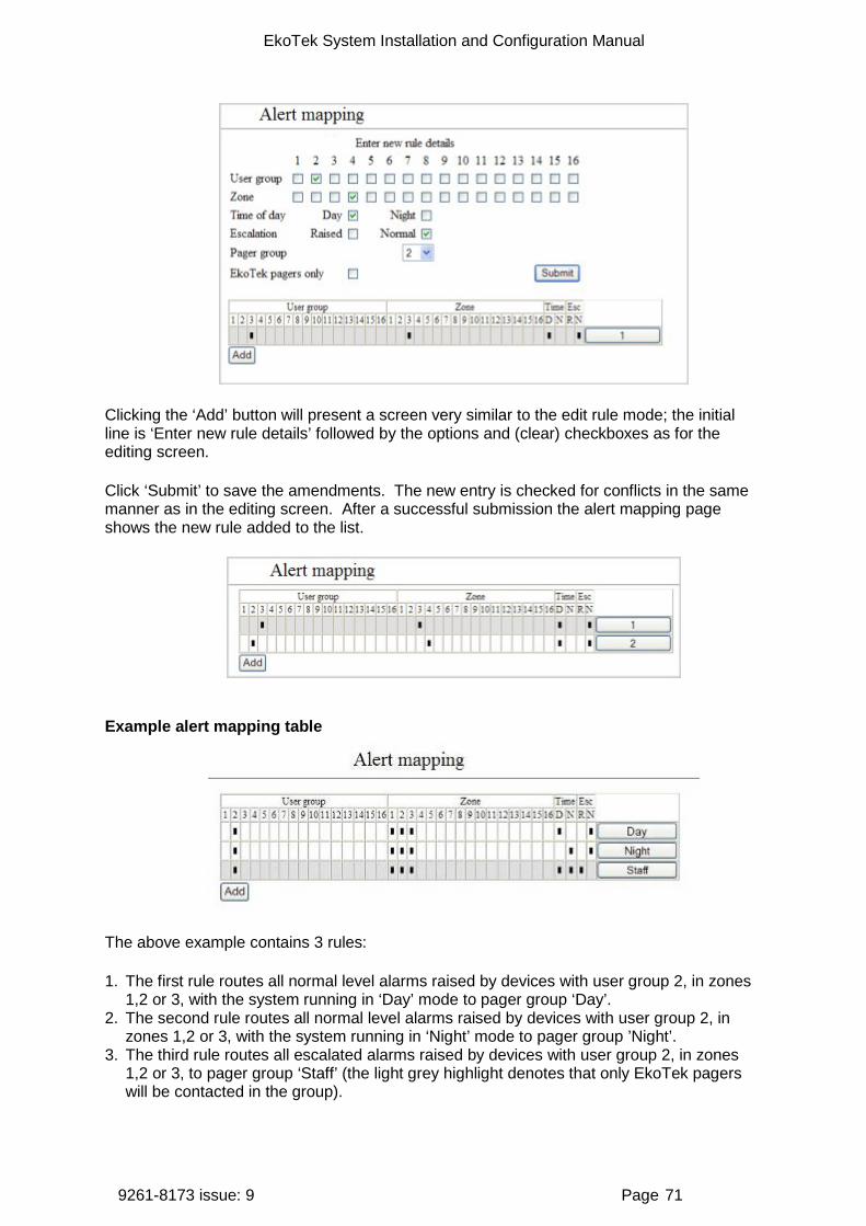
EkoTek System Installation and Configuration Manual
9261-8173 issue: 9 Page 71
Clicking the ‘Add’ button will present a screen very similar to the edit rule mode; the initial line is ‘Enter new rule details’ followed by the options and (clear) checkboxes as for the editing screen.
Click ‘Submit’ to save the amendments. The new entry is checked for conflicts in the same manner as in the editing screen. After a successful submission the alert mapping page shows the new rule added to the list.
Example alert mapping table
The above example contains 3 rules:
1. The first rule routes all normal level alarms raised by devices with user group 2, in zones 1,2 or 3, with the system running in ‘Day’ mode to pager group ‘Day’.
2. The second rule routes all normal level alarms raised by devices with user group 2, in zones 1,2 or 3, with the system running in ‘Night’ mode to pager group ’Night’.
3. The third rule routes all escalated alarms raised by devices with user group 2, in zones 1,2 or 3, to pager group ‘Staff’ (the light grey highlight denotes that only EkoTek pagers will be contacted in the group).

EkoTek System Installation and Configuration Manual
9261-8173 issue: 9 Page 72
All other alarms will be routed by (default) to pager group 1.
Factory reset
Click the ‘Factory reset’ button to return the network to factory settings (all devices deleted, IP addresses, passwords reset, etc).
Delete all devices
Click the ‘Clear database’ button to clear the database of all network devices, but leave passwords, IP addresses, etc. as before.
Passwords
Change the system passwords.
‘User’ followed by a drop-down menu containing:
User The User level allows viewing access to all pages within the main and maintenance menus and to the passwords page under the configuration menu (it can only change the password for user).
Admin The admin level allows access to all functions.
New password Enter new password in the text input box. Click ‘Submit’ to enter the new password.
‘User/admin password changed’ or ‘Password change failed’ will be displayed, according to the outcome.
A password change failure may also be accompanied by: ‘New password must be between 4 and 8 characters long’ if the password length is invalid, or ‘You do not have permission to
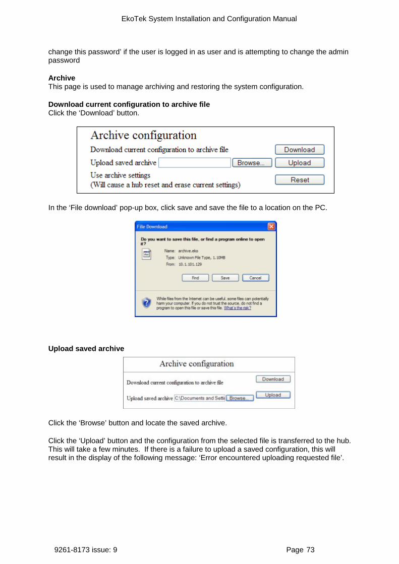
EkoTek System Installation and Configuration Manual
9261-8173 issue: 9 Page 73
change this password’ if the user is logged in as user and is attempting to change the admin password
Archive This page is used to manage archiving and restoring the system configuration.
Download current configuration to archive file Click the ‘Download’ button.
In the ‘File download’ pop-up box, click save and save the file to a location on the PC.
Upload saved archive
Click the ‘Browse’ button and locate the saved archive.
Click the ‘Upload’ button and the configuration from the selected file is transferred to the hub. This will take a few minutes. If there is a failure to upload a saved configuration, this will result in the display of the following message: ‘Error encountered uploading requested file’.
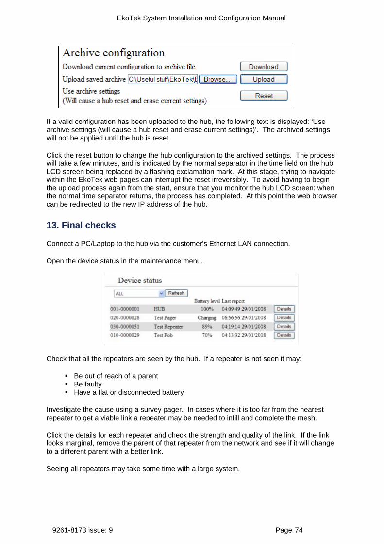
EkoTek System Installation and Configuration Manual
9261-8173 issue: 9 Page 74
If a valid configuration has been uploaded to the hub, the following text is displayed: ‘Use archive settings (will cause a hub reset and erase current settings)’. The archived settings will not be applied until the hub is reset.
Click the reset button to change the hub configuration to the archived settings. The process will take a few minutes, and is indicated by the normal separator in the time field on the hub LCD screen being replaced by a flashing exclamation mark. At this stage, trying to navigate within the EkoTek web pages can interrupt the reset irreversibly. To avoid having to begin the upload process again from the start, ensure that you monitor the hub LCD screen: when the normal time separator returns, the process has completed. At this point the web browser can be redirected to the new IP address of the hub.
13. Final checks
Connect a PC/Laptop to the hub via the customer’s Ethernet LAN connection.
Open the device status in the maintenance menu.
Check that all the repeaters are seen by the hub. If a repeater is not seen it may:
Be out of reach of a parent Be faulty Have a flat or disconnected battery
Investigate the cause using a survey pager. In cases where it is too far from the nearest repeater to get a viable link a repeater may be needed to infill and complete the mesh.
Click the details for each repeater and check the strength and quality of the link. If the link looks marginal, remove the parent of that repeater from the network and see if it will change to a different parent with a better link.
Seeing all repeaters may take some time with a large system.

EkoTek System Installation and Configuration Manual
9261-8173 issue: 9 Page 75
Register a pager and a call fob using auto-register and see if an alarm from the call fob is received at the pager and that the response is sent to the fob on the network. This will check correct configuration of alert rules and groups
This completes the installation.
14. Configuring SERs
Connecting to SER
The SER is connected to the hub via the customer’s LAN network using standard CAT5 cable with an RJ45 connector. The SER is shown using a PoE injector supplied as standard. (This LAN must be a solid guaranteed reliable connection).
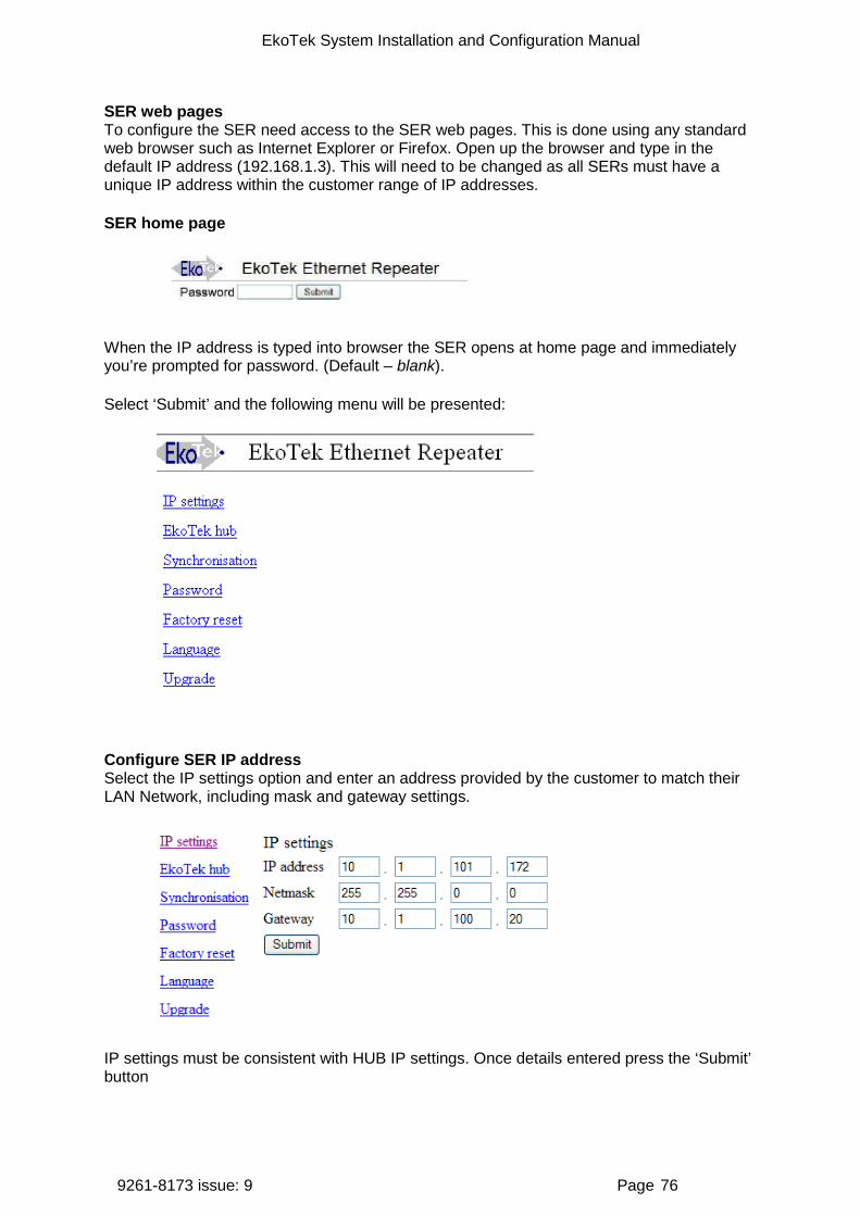
EkoTek System Installation and Configuration Manual
9261-8173 issue: 9 Page 76
SER web pages To configure the SER need access to the SER web pages. This is done using any standard web browser such as Internet Explorer or Firefox. Open up the browser and type in the default IP address (192.168.1.3). This will need to be changed as all SERs must have a unique IP address within the customer range of IP addresses.
SER home page
When the IP address is typed into browser the SER opens at home page and immediately you’re prompted for password. (Default – blank).
Select ‘Submit’ and the following menu will be presented:
Configure SER IP address Select the IP settings option and enter an address provided by the customer to match their LAN Network, including mask and gateway settings.
IP settings must be consistent with HUB IP settings. Once details entered press the ‘Submit’ button
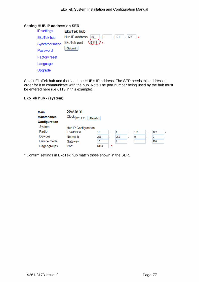
EkoTek System Installation and Configuration Manual
9261-8173 issue: 9 Page 77
Setting HUB IP address on SER
Select EkoTek hub and then add the HUB’s IP address. The SER needs this address in order for it to communicate with the hub. Note The port number being used by the hub must be entered here (i.e 6113 in this example).
EkoTek hub - (system)
* Confirm settings in EkoTek hub match those shown in the SER.
*
*
*
*
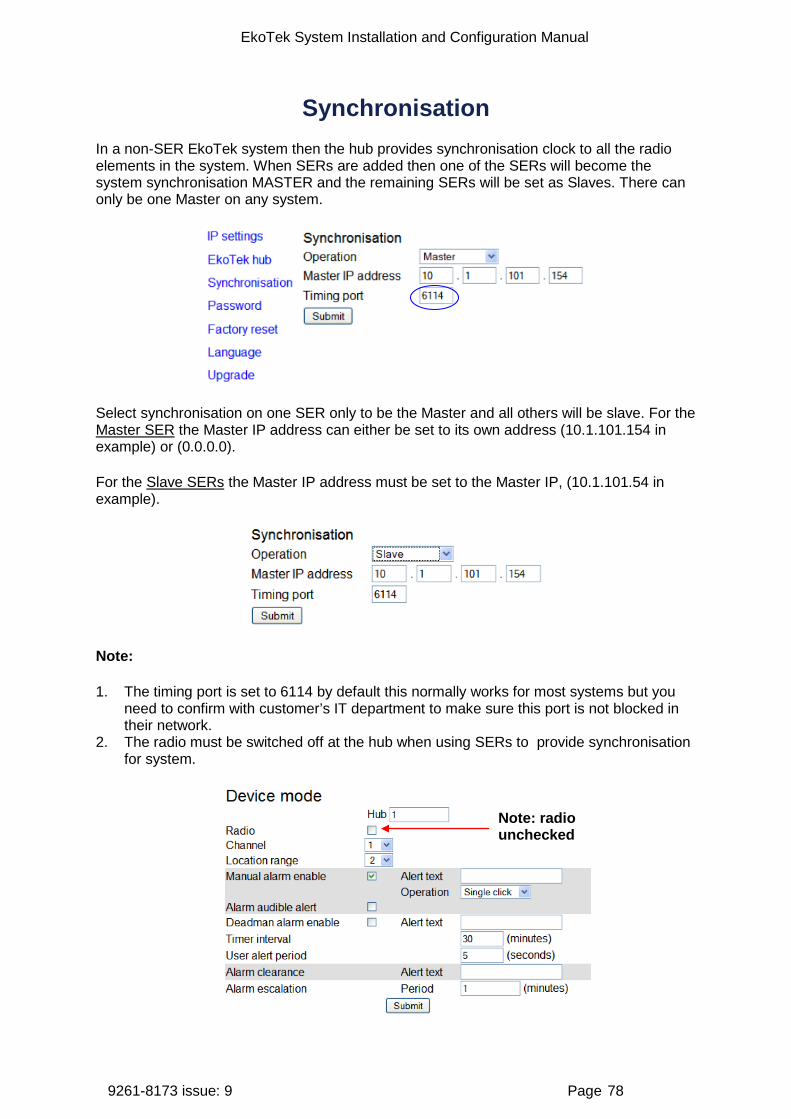
EkoTek System Installation and Configuration Manual
9261-8173 issue: 9 Page 78
Synchronisation In a non-SER EkoTek system then the hub provides synchronisation clock to all the radio elements in the system. When SERs are added then one of the SERs will become the system synchronisation MASTER and the remaining SERs will be set as Slaves. There can only be one Master on any system.
Select synchronisation on one SER only to be the Master and all others will be slave. For the Master SER the Master IP address can either be set to its own address (10.1.101.154 in example) or (0.0.0.0).
For the Slave SERs the Master IP address must be set to the Master IP, (10.1.101.54 in example).
Note:
1. The timing port is set to 6114 by default this normally works for most systems but you need to confirm with customer’s IT department to make sure this port is not blocked in their network.
2. The radio must be switched off at the hub when using SERs to provide synchronisation for system.
Note: radio unchecked
EkoTek System Installation and Configuration Manual
9261-8173 issue: 9 Page 79
Appendix 1: Miscellaneous system messages The following on-system messages are generated in addition to alert texts configured using the web server interface.
1. Personal security messages
Accepted Generated as a consequence of a pager accepting a raised alarm.
2. Pager response messages
Delivered
Accepted
Rejected
Denoting the delivery acknowledgement and appropriate user acceptance or rejection.
3. Maintenance messages
Low battery Generated from the Hub when the battery level drops to 20%, will be re-generated for every further 3% drop
Replace battery Generated from the Hub at 5% battery level and regenerated for every further drop.
Maintenance required If a fixed device fails to report its status as scheduled on 4 consecutive occasions (each report sent at 4.5 hour intervals) and if the device remains persistently not reporting its status (i.e. a further 6 consecutive missed status reports), a ‘Maintenance required’ message is generated.

EkoTek System Installation and Configuration Manual
9261-8173 issue: 9 Page 80
Appendix 2: Specifications Radio frequency 2405 – 2480MHz Radio channels 16 Channel operating mode Fixed frequency, or frequency hopping Maximum number of radio channels simultaneously used per system 16
Radio power 10mW Radio coding CDMA IEEE 802.15.4 Hub power AC-DC power adaptor Hub backup batteries 3 x C cell NiMH rechargeable batteries
Repeater power 2 x D cell high capacity alkaline manganese batteries
Pager power 1 x AAA cell high capacity alkaline manganese, or NiMH rechargeable battery
Call fob power 1 x AAA cell high capacity alkaline manganese, or NiMH rechargeable battery
Assist pager power 1 x soldered AAA NiMH battery Assist fob power 1 x soldered AAA NiMH battery Solar repeater power Proprietary battery pack
Mains powered repeater power 9.5-15V DC 15mA, with proprietary rechargeable battery pack as backup
Charging rack AC-DC power adaptor
Call point 2 x D cell high capacity alkaline manganese batteries
Mains powered call point 11 – 15v 25mA , with proprietary rechargeable battery pack as backup
Maximum number of repeaters per radio channels 90
Maximum number of pagers 127 Maximum number of pagers in a pager group 35
Maximum number of devices per system 500
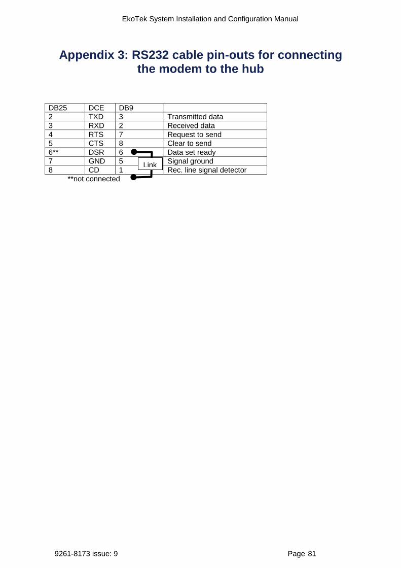
EkoTek System Installation and Configuration Manual
9261-8173 issue: 9 Page 81
Appendix 3: RS232 cable pin-outs for connecting the modem to the hub
DB25 DCE DB9 2 TXD 3 Transmitted data 3 RXD 2 Received data 4 RTS 7 Request to send 5 CTS 8 Clear to send 6** DSR 6 Data set ready 7 GND 5 Signal ground 8 CD 1 Rec. line signal detector
**not connected
Link

EkoTek System Installation and Configuration Manual
9261-8173 issue: 9 Page 82
Appendix 4A: Overlapping system support
1. Overview
With complex network setups advice should always be sought from Multitone Customer Services for assistance when planning this type of Installation.
Overlapping System Support (OSS) allows the mesh network radio footprint of multiple hubs to overlap. This may be necessary, for example, where different departments of an organisation have their own independent overlapping EkoTek systems, or where there are fringe radio areas where the networks of multiple hubs overlap.
Each network needs to be set with different network identifiers and radio channels. Frequency hopping is forbidden with OSS.
2. Overlapping and mobile roaming systems
Two possible configurations for overlapping systems are supported when not using SERs.
A. Overlapping networks, where two networks substantially overlap at the same location. This could be used to provide exclusive networks within the same area each with its own population of pagers and call fobs.
B. Mobile roaming networks, where pagers and call fobs roam between the two networks. In order that pagers and call fobs hand over upon entry to an adjacent network it is important to design the networks to have minimum overlap to give a clear indication of the zone where the pager or call fob is located. This also ensures that pagers and call fobs
Overlapping networks
Network A
Network B
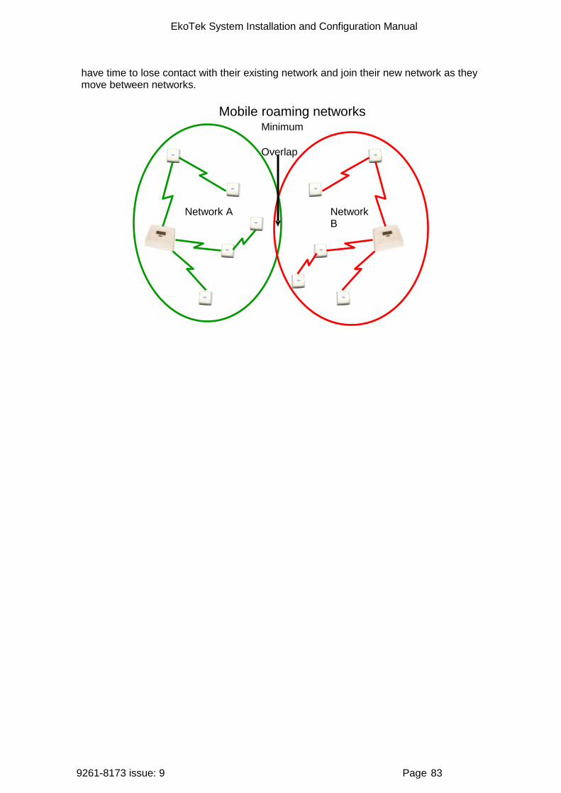
EkoTek System Installation and Configuration Manual
9261-8173 issue: 9 Page 83
have time to lose contact with their existing network and join their new network as they move between networks.
Network B
Network A
Mobile roaming networks Minimum
Overlap
EkoTek System Installation and Configuration Manual
9261-8173 issue: 9 Page 84
Appendix 4B: Channel allocation with SER
1. Overview
The SERs is used in a customer network to provide synchronised radio coverage over a larger site without having to resort to separate or overlapping systems. The repeater operates in a similar way to a normal repeater except for the fact it is linked back to the hub via the customer’s LAN. Each SER is allocated its own channels to operate in its own area and link with the other repeaters in its vicinity, because it is linked back via the LAN it does not need to be able to reach back to the hub via the radio path.
This helps to reduce long chains of repeaters across a larger site and means set channels can be used in different areas of a large site. This helps to ensure a stable radio network. Linking between buildings can be done using SERs via LAN where before a ‘chain of repeaters’ would have been required (this helps by reducing the overall device count on the system).
With complex network setups advice should always be sought from Multitone Customer Services for assistance when planning this type of installation.

EkoTek System Installation and Configuration Manual
9261-8173 issue: 9 Page 85
Appendix 5: Remote logging protocol
1. Overview of logging
The remote logging facility can be used for real time recording and remote storage of system events. Third parties are able to make use of the hub’s remote logging output and external system input as a low level RS232 paging interface with higher level application software creating more sophisticated functions. For example, an application could be created to page staff members closest to the location where a request for assistance is made from, or to display the location of an individual on a graphical site plan, or to send an SMS message when a location alarm is raised.
The logging output from the hub supports output of the following message types:
Paging messages Output each time a paging message is sent or responded to.
Location report Output each time a device with location reporting enabled changes location.
Personal security alarm Output when PS alarms are raised/cleared.
Maintenance message Output when maintenance messages are raised e.g. low battery alarms from repeaters.
Remote logging information is sent within a payload of SysLog formatted messages. It is sent to UDP port 514 of the IP address specified on the system configuration page. No check is made to ensure that the machine is present.
Remote debug logging The hub also supports low-level message debug logging. This can be used by Multitone for the diagnosis of network problems, but in a standard running system should be set to ‘Off’. In order to differentiate between debug and event logging different SysLog levels are used. Event logging is priority ‘info’ and debug logging is priority ‘debug’.
2. General formatting
Remote logging messages can be set to numeric only, text only or a combination of numeric and text. These combinations allow the output to be easily human or machine readable as required.
Tabs delimit the fields.
All fields are present in all messages, even if empty, unless no more fields are to be filled in, where the line is then newline terminated.
Message always terminated by newline. Output can be off, numeric, text or numeric and text.
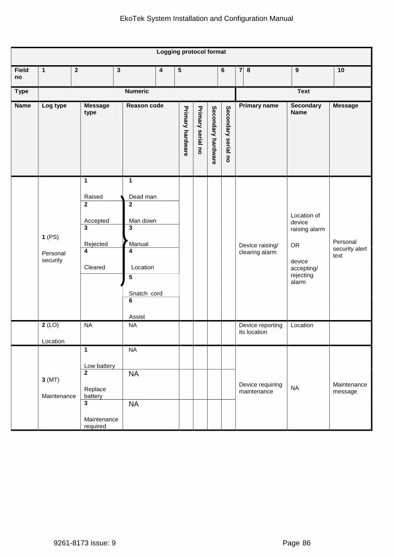
EkoTek System Installation and Configuration Manual
9261-8173 issue: 9 Page 86
Logging protocol format
Field no
1 2 3 4 5 6 7 8 9 10
Type Numeric Text
Name Log type Message type
Reason code Primary hardw
are
Primary serial no
Secondary hardware
Secondary serial no
Primary name Secondary Name
Message
1 (PS)
Personal security
1
Raised
1
Dead man
Device raising/ clearing alarm
Location of device raising alarm
OR
device accepting/ rejecting alarm
Personal security alert text
2
Accepted
2
Man down 3
Rejected
3
Manual 4
Cleared
4
Location 5
Snatch cord 6
Assist 2 (LO)
Location
NA NA Device reporting its location
Location
3 (MT)
Maintenance
1
Low battery
NA
Device requiring maintenance NA Maintenance
message
2
Replace battery
NA
3
Maintenance required
NA

EkoTek System Installation and Configuration Manual
9261-8173 issue: 9 Page 87
Logging protocol format
Field no 1 2 3 4 5 6 7 8 9 10
Name Log type
Message type
Reason code
Primary hardw
are
Primary serial no
Secondary hardware
Secondary serial no
Primary name
Secondary name
Message
Type Numeric Text
4 (PG)
Paging
1 Message
1
No response required
Individually addressed destination pager/ responding pager
or
0,0 for broadcast
or
0,pager group number for pager group
NA NA
Blank for broadcast,
or
pager group name,
or
individual pager name
NA
Message text / delivery report / user response
2
Delivery report required 3
User response required 4
Delivery report & user response required 5
Externally generated message
2 Delivery report
NA
3 Message response
1 Accept 2 Reject
3. Log examples
Key: Green: all SysLog messages; yellow: numeric output selected; blue: Text output selected.
PS: Call fob raising manual alarm at reception repeater.
Note: The numbers in columns 4 to 7 are example serial number data. These will be repeated throughout, but are omitted for clarity.
1 1 3 010
1000039
030 0045096
Call fob 1 Reception Assist

EkoTek System Installation and Configuration Manual
9261-8173 issue: 9 Page 88
PS: Pager accepting (manual) alarm raised by call fob.
LO: Pager moving within range of hub.
MT: Repeater not reporting status.
PG: Message to all pagers, no response request.
PG: Message to pager group 1, response requested.
PG: Delivery report from pager.
PG: Accept response from pager.
PG: Reject response from pager.
1 2 3 010
1000039
020 0098354
Call fob 1 Pager 1 Accepted
1 020
0098354
001 0023076
Pager 1 The hub
3 1 030
0045096
Reception Maintenance required
4 1 1 0 0 The message sent
4 1 3 0 1 Group 1 The message sent
4 2 030
0045096
Pager 1 Delivered
4 3 1 030
0045096
Pager 1 Accepted

EkoTek System Installation and Configuration Manual
9261-8173 issue: 9 Page 89
4 3 2 030
0045096
Pager 1 Rejected

EkoTek System Installation and Configuration Manual
9261-8173 issue: 9 Page 90
Appendix 6: External system connections If the hub’s external system interface is to be used, a link is connected to the serial port. The data rate should be set to the link speed (options are 300, 600, 1200, 2400, 4800 and 9600 bits per second). The data format and flow control should be set to match that of the receiving device (options are 7 bit even parity or 8 bit no parity with 1 or 2 stop bits). Messages will be truncated to 138 characters for TAP messages and 128 characters for ESPA messages.
Only a single selection from those below can be made on the hub; bidirectional paging operation has limited support by using Port A for Output and Port B as an Input.
Options are: port A
ESPA input (maximum 138 characters). Note that 128 characters are defined by the standard
ESPA output (maximum 101 characters, because only alarms are sent via this interface). Note that 128 characters are defined by the standard
TAP input (maximum 138 characters) TAP output (maximum 101 characters, because only alarms are sent via this interface)
Options are: Port B
ESPA input (maximum 138 characters). Note that 128 characters are defined by the standard
TAP input (maximum 138 characters)
Incoming pager messages are addressed as follows:
0 = all pagers
1-32 = pager group
HHHNNNNNNN for individual pagers where HHH = hardware type and NNNNNNN = serial number.
Note: ESPA and TAP protocols do not have standardised third party implementations – a test with third party equipment is necessary.
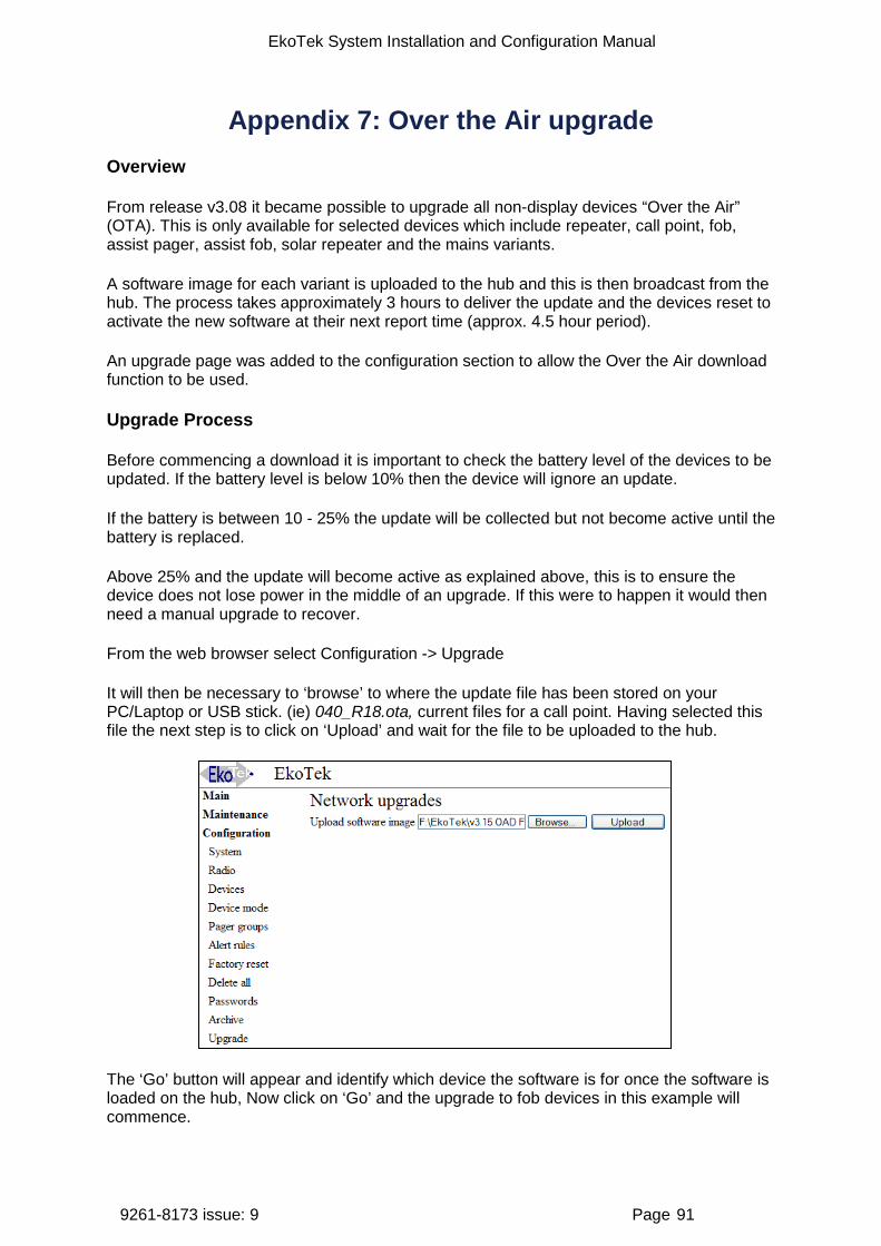
EkoTek System Installation and Configuration Manual
9261-8173 issue: 9 Page 91
Appendix 7: Over the Air upgrade Overview
From release v3.08 it became possible to upgrade all non-display devices “Over the Air” (OTA). This is only available for selected devices which include repeater, call point, fob, assist pager, assist fob, solar repeater and the mains variants.
A software image for each variant is uploaded to the hub and this is then broadcast from the hub. The process takes approximately 3 hours to deliver the update and the devices reset to activate the new software at their next report time (approx. 4.5 hour period).
An upgrade page was added to the configuration section to allow the Over the Air download function to be used.
Upgrade Process
Before commencing a download it is important to check the battery level of the devices to be updated. If the battery level is below 10% then the device will ignore an update.
If the battery is between 10 - 25% the update will be collected but not become active until the battery is replaced.
Above 25% and the update will become active as explained above, this is to ensure the device does not lose power in the middle of an upgrade. If this were to happen it would then need a manual upgrade to recover.
From the web browser select Configuration -> Upgrade
It will then be necessary to ‘browse’ to where the update file has been stored on your PC/Laptop or USB stick. (ie) 040_R18.ota, current files for a call point. Having selected this file the next step is to click on ‘Upload’ and wait for the file to be uploaded to the hub.
The ‘Go’ button will appear and identify which device the software is for once the software is loaded on the hub, Now click on ‘Go’ and the upgrade to fob devices in this example will commence.
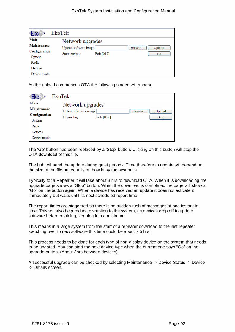
EkoTek System Installation and Configuration Manual
9261-8173 issue: 9 Page 92
As the upload commences OTA the following screen will appear:
The ‘Go’ button has been replaced by a ‘Stop’ button. Clicking on this button will stop the OTA download of this file.
The hub will send the update during quiet periods. Time therefore to update will depend on the size of the file but equally on how busy the system is.
Typically for a Repeater it will take about 3 hrs to download OTA. When it is downloading the upgrade page shows a “Stop” button. When the download is completed the page will show a “Go” on the button again. When a device has received an update it does not activate it immediately but waits until its next scheduled report time.
The report times are staggered so there is no sudden rush of messages at one instant in time. This will also help reduce disruption to the system, as devices drop off to update software before rejoining, keeping it to a minimum.
This means in a large system from the start of a repeater download to the last repeater switching over to new software this time could be about 7.5 hrs.
This process needs to be done for each type of non-display device on the system that needs to be updated. You can start the next device type when the current one says “Go” on the upgrade button. (About 3hrs between devices).
A successful upgrade can be checked by selecting Maintenance -> Device Status -> Device -> Details screen.

EkoTek System Installation and Configuration Manual
9261-8173 issue: 9 Page 93
Revision history and related documentation
1. Revision history
Issue Date Author Revision 1 June 2007 M Windett Initial Document 2 30.08.07 R Robertson Production Issue 3 January 2008 M Windett Update for System Release 3 Sub Release 1 4 July 2008 M Windett Update for System Release 3 Sub Release 2 5 August 2008 D Neale Corrections and addition of new products 6 18.06.09 Gooding Latest Base and revise the drill diameter 7 03.11.09 D Neale Added mains powered repeater 8 13.01.12 D.Simpson Review Document & Update 9 12.08.13 D.Simpson Update after introduction of New Pagers & Fobs
2. Related documentation
Title Part Number EkoTek Pager User Guide 9261-8275 EkoTek Hub User Guide 9261-8276 EkoTek Call Fob User Guide 9261-8277 EkoTek Call Fob Quick Instructions 9261-8311 EkoTek Pager Quick Instructions 9261-8312 EkoTek Hub Help Files (HTML) 4761-8313 EkoTek Assist Pager Quick Guide 9261-9210 EkoTek Assist Fob Quick Guide 9261-9209
Document number: 9261-8173