ekor - Ormazabal · LIB ekor.stp Programmable transfer unit General instructions IG-164-EN, version...
28
LIB ekor.stp Programmable transfer unit General instructions IG-164-EN, version 04, 06/04/2017
Transcript of ekor - Ormazabal · LIB ekor.stp Programmable transfer unit General instructions IG-164-EN, version...
LIB
ekor.stp Programmable transfer unit
General instructionsIG-164-EN, version 04, 06/04/2017
In view of the constant evolution in standards and design, the characteristics of the elements contained in this manual are subject to change without prior notice. These characteristics, as well as the availability of components, are subject to confirmation by Ormazabal.
CAUTION!
When medium-voltage equipment is operating, certain components are live, other parts may be in movement and some may reach high temperatures. Therefore, the use of this equipment poses electrical, mechanical and thermal risks.
In order to ensure an acceptable level of protection for people and property, and in compliance with applicable environmental recommendations, Ormazabal designs and manufactures its products according to the principle of integrated safety, based on the following criteria:
• Elimination of hazards wherever possible. • Where elimination of hazards is neither technically nor economically feasible, appropriate protection functions are
incorporated in the equipment. • Communication about remaining risks to facilitate the design of operating procedures which prevent such risks,
training for the personnel in charge of the equipment, and the use of suitable personal protective equipment. • Use of recyclable materials and establishment of procedures for the disposal of equipment and components so
that once the end of their service lives is reached, they are duly processed in accordance, as far as possible, with the environmental restrictions established by the competent authorities.
Consequently, the equipment to which the present manual refers complies with the requirements of section 11.2 of Standard IEC 62271-1. It must therefore only be operated by appropriately qualified and supervised personnel, in accordance with the requirements of standard EN 50110-1 on the safety of electrical installations and standard EN 50110-2 on activities in or near electrical installations. Personnel must be fully familiar with the instructions and warnings contained in this manual and in other recommendations of a more general nature which are applicable to the situation according to current legislation[1].
The above must be carefully observed, as the correct and safe operation of this equipment depends not only on its design but also on general circumstances which are in general beyond the control and responsibility of the manufacturer. More specifically:
• The equipment must be handled and transported appropriately from the factory to the place of installation. • All intermediate storage should occur in conditions which do not alter or damage the characteristics of the equipment
or its essential components. • Service conditions must be compatible with the equipment rating. • The equipment must be operated strictly in accordance with the instructions given in the manual, and the applicable
operating and safety principles must be clearly understood. • Maintenance should be performed properly, taking into account the actual service and environmental conditions in
the place of installation.
The manufacturer declines all liability for any significant indirect damages resulting from violation of the guarantee, under any jurisdiction, including loss of income, stoppages and costs resulting from repair or replacement of parts.
Warranty
The manufacturer guarantees this product against any defect in materials and operation during the contractual period. In the event that defects are detected, the manufacturer may opt either to repair or replace the equipment. Improper handling of this equipment and its repair by the user shall constitute a violation of the guarantee.
Registered Trademarks and Copyrights
All registered trademarks cited in this document are the property of their respective owners. The intellectual property of this manual belongs to Ormazabal.
[1] For example, in Spain the “Regulation on technical conditions and guarantees for safety in high-voltage electrical installations” – Royal Decree 337/2014 is obligatory.
General instructionsekor.stp
Contents
IG-164-EN version 04; 06/04/2017 3
Contents
1. General description ...................................................4
2. ekor.stp equipment ....................................................5
2.1. Medium-voltage cubicles . . . . . . . . . . . . . . . . . . . .52.2. ekor.rtk voltage presence/absence unit . . . . . .62.3. Control box . . . . . . . . . . . . . . . . . . . . . . . . . . . . . . . . . .62.4. ekor.rpg.ci. . . . . . . . . . . . . . . . . . . . . . . . . . . . . . . . . . .72.5. ekor.ccp. . . . . . . . . . . . . . . . . . . . . . . . . . . . . . . . . . . . .72.6. CE Conformity . . . . . . . . . . . . . . . . . . . . . . . . . . . . . . .8
3. Application description .............................................9
3.1. Automatic mode . . . . . . . . . . . . . . . . . . . . . . . . . . . . .93.2. Manual mode. . . . . . . . . . . . . . . . . . . . . . . . . . . . . . .113.2.1. Remote operation. . . . . . . . . . . . . . . . . . . . . . . . . . .113.2.2. Operation using push-buttons . . . . . . . . . . . . . .113.2.3. Direct operation from the cubicle. . . . . . . . . . . .123.2.4. Operation from the ekor.ccp unit. . . . . . . . . . . .12
4. Navigating the ekor.ccp menu ................................13
4.1. Introduction to the ekor.ccp interface . . . . . . .134.2. Menus system . . . . . . . . . . . . . . . . . . . . . . . . . . . . . .164.3. Parameters . . . . . . . . . . . . . . . . . . . . . . . . . . . . . . . . .164.3.1. Date and time setting . . . . . . . . . . . . . . . . . . . . . . .164.3.2. Adjusting timings . . . . . . . . . . . . . . . . . . . . . . . . . . .174.4. Alarms. . . . . . . . . . . . . . . . . . . . . . . . . . . . . . . . . . . . . .174.5. Definition of events log texts . . . . . . . . . . . . . . . .18
5. Commissioning instructions ...................................19
5.1. Control equipment power supply. . . . . . . . . . . .195.1.1. Activating the equipment . . . . . . . . . . . . . . . . . . .195.1.2. Precautions during commissioning . . . . . . . . . .195.2. Checking information on the main screen . . .195.2.1. Presence of electrical voltage. . . . . . . . . . . . . . . .195.2.2. Voltage presence simulation . . . . . . . . . . . . . . . .205.2.3. Switch positions . . . . . . . . . . . . . . . . . . . . . . . . . . . .215.3. Entering and leaving the transformer
substation . . . . . . . . . . . . . . . . . . . . . . . . . . . . . . . . . .21
6. Anomalies .................................................................22
7. Associated documentation .....................................24
IG-164-EN version 04; 06/04/20174
General description General instructionsekor.stp
1. General description
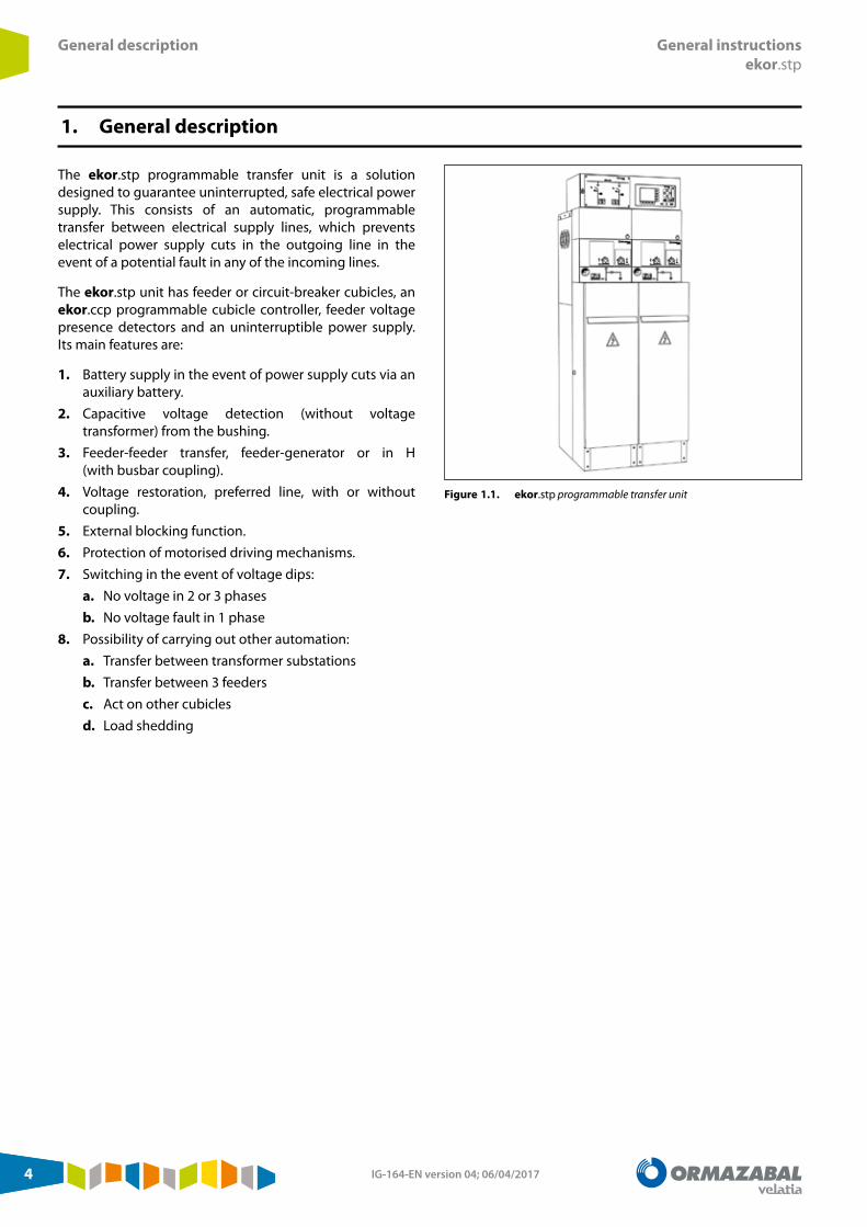
The ekor.stp programmable transfer unit is a solution designed to guarantee uninterrupted, safe electrical power supply. This consists of an automatic, programmable transfer between electrical supply lines, which prevents electrical power supply cuts in the outgoing line in the event of a potential fault in any of the incoming lines.
The ekor.stp unit has feeder or circuit-breaker cubicles, an ekor.ccp programmable cubicle controller, feeder voltage presence detectors and an uninterruptible power supply. Its main features are:
1. Battery supply in the event of power supply cuts via an auxiliary battery.
2. Capacitive voltage detection (without voltage transformer) from the bushing.
3. Feeder-feeder transfer, feeder-generator or in H (with busbar coupling).
4. Voltage restoration, preferred line, with or without coupling.
5. External blocking function.6. Protection of motorised driving mechanisms.7. Switching in the event of voltage dips:
a. No voltage in 2 or 3 phasesb. No voltage fault in 1 phase
8. Possibility of carrying out other automation:a. Transfer between transformer substationsb. Transfer between 3 feedersc. Act on other cubiclesd. Load shedding
Figure 1.1. ekor.stp programmable transfer unit

IG-164-EN version 04; 06/04/2017 5
General instructionsekor.stp
ekor.stp equipment
2. ekor.stp equipment
2.1. Medium-voltage cubicles
The set is made up of switch-disconnector cubicles or circuit-breaker cubicles. Each of these provides electrical energy to the installation from a different electrical supply line, which allows of them to be used in the event of a supply fault from the other.
This solution is very popular in important facilities such as hospitals, factories or hotels where a continuous electrical current is required. In accordance with the criticality of the load, it is possible to choose to install feeder cubicles or circuit-breaker cubicles, with the main difference being the time taken for the unit to make the transfer Table 2.1.
Topology Conventional controlLine-line < 8 s
Breaker-breaker < 0.8 s
Table 2.1. Transfer times depending on the topology
More advanced solutions are also carried out for more complex installations, which include the following:
1. Network-set transfer, if there is internal generation. Transfer between outdoor incoming feeder and generator set.
2. Transfer between busbar couplings for integrated transformer substations in ring distribution.
3. H transfer for switching substations. Transfer between incoming feeders for switching substations with split busbar topology.
4. Advanced automation to manage load shedding or management of the transfer between different switching substations such as IT servers, hospitals or tunnels.
Below, electrical diagrams are displayed as an example of the proposed solutions.
Figure 2.1. Network-set transfer
Figure 2.2. H transfer using breaker.
Figure 2.3. H transfer using busbar switch.

IG-164-EN version 04; 06/04/20176
ekor.stp equipment General instructionsekor.stp
2.2. ekor.rtk voltage presence/absence unit
The ekor.rtk unit is electronic equipment developed to detect the presence and absence of voltage in medium-voltage (MV) lines.
This unit is installed in automatic transfers between two supplies equipped with a switch-disconnector or between two supplies equipped with circuit-breakers without protection relays that can perform the function of detecting voltage presence.
The unit is built into the switchgear and uses the same signals as the ekor.vpis voltage presence indicators to perform detection functions. Thus, conventional MV line coupling systems such as voltage transformers are not required.
The ekor.rtk is supplied duly installed, configured and tested at factory, and integrated in the cubicles.
For more information on the functional and technical specifications or electrical diagrams of this unit, see IG-094. 1 ekor.rtk to ekor.vpis relay cable
2 Support for ekor.rtk relay in circuit-breaker cubicles
3 Support for ekor.rtk relay in feeder cubicles
4 Bushing to ekor.rtk relay cable
5 User terminal block
6 ekor.vpis voltage presence indication
7 ekor.rtk relay to user terminal block cable
8 User terminal block
Figure 2.4. ekor.rtk unit detail
2.3. Control box
The main elements included in the ekor.stp control box are as follows:
1. Charger with 230 Vac input and 2.5 A output.2. 48Vdc battery with capacity for 4 Ah, for the transfer
between feeder cubicles or 7 Ah for circuit-breaker cubicles.
3. Manual operation push-buttons for 2 incoming lines.4. 3 miniature circuit-breakers: 2 of them protect the
auxiliary LV elements of each feeder cubicle, while the third one protects the ekor.ccp unit's power supply.
5. ekor.ccp: Programmable cubicle controller.
Figure 2.5. ekor.ccp unit and manual operation push-buttons.
Figure 2.6. Battery and miniature circuit-breakers, and electrical connection terminals

IG-164-EN version 04; 06/04/2017 7
General instructionsekor.stp
ekor.stp equipment
2.4. ekor.rpg.ci
The ekor.rpg.ci protection, metering and control unit, depending on the model, may incorporate overcurrent protection functions as well as other functions such as local control, remote control, electrical parameter measurement, presence and absence of voltage, automation, recloser, phase unbalance and cumulative breaking current value, among others.
In the case of automatic transfer, its function consists of sending the voltage presence/absence signal in the incoming line, in addition to tripping the circuit-breaker in the event of an overtravel fault. The signals are sent using two physical outputs of the ekor.rpg.ci, leading to 2 inputs of the ekor.ccp.
For more information on the functional and technical specifications or electrical diagrams of this unit, see IG-157.
Figure 2.7. ekor.rpg.ci protection, metering and control unit
2.5. ekor.ccp
The programmable cubicle controller ekor.ccp is the unit in charge of managing the line transfer. It is a flexible, programmable microprocessor system with PC structure and Linux operating system, which enables use in remote-controlled installations, supporting a large number of protocols.
Its 320x240 graphic display allows the single-wire diagram of the installation to be displayed, along with history log data (up to 1792 events), alarms, etc., of the medium-voltage installation.
The front panel is fitted with an RS-232 port and an Ethernet port to configure the unit.
The ekor.ccp unit includes a Web server that is accessible in local mode and in remote mode via any of the Ethernet ports on the unit. Alarms and logs can be checked through this server. The web page can be accessed from any web browser, either locally or remotely. To enable remote access, it is necessary to install and configure communications equipment with WAN access connected to the ekor.ccp unit, which is not included in the ekor.stp.
Figure 2.8. ekor.ccp controller view

IG-164-EN version 04; 06/04/20178
ekor.stp equipment General instructionsekor.stp
The following table gives a summary of the technical specifications of the ekor.ccp unit.
Power supply Voltage range 30 Vdc to 80 Vdc
Rated ConsumptionWith display on and all outputs activated
21 W30 W
Digital inputsVia cardMaximum capacityPolarisation voltage
12 inputs48 inputs 30 Vdc to 80 Vdc
Digital outputs
TypeVia cardMaximum capacityContacts
Volt-free contacts6 outputs24 outputs5A/250 Vac/resistive
Temperature Operation - 10 °C...+ 60 °C
Storage - 25 °C...+ 70 °C
CPU RAM 16 MB
Real time clock hh: mm: ss: dd
Event log 1792
Graphic capacity Up to 6 cubicles are viewed on the display
Table 2.2. ekor.ccp characteristics summary
For more information on the functional and technical specifications or electrical diagrams of this unit, see IG-156.
2.6. CE Conformity
This product complies with European Union Directive 2014/30/EU on electromagnetic compatibility, and with IEC 60255 international regulations. The unit has been designed and manufactured for use in industrial areas, in accordance with EMC standards. This conformity is a result of the test carried out in accordance with article 7 of the Directive.
IG-164-EN version 04; 06/04/2017 9
General instructionsekor.stp
Application description
3. Application description
3.1. Automatic mode
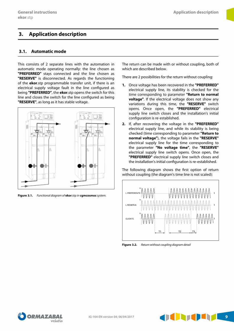
This consists of 2 separate lines with the automation in automatic mode operating normally: the line chosen as "PREFERRED" stays connected and the line chosen as "RESERVE" is disconnected. As regards the functioning of the ekor.stp programmable transfer unit, if there is an electrical supply voltage fault in the line configured as being "PREFERRED", the ekor.stp opens the switch for this line and closes the switch for the line configured as being "RESERVE", as long as it has stable voltage.
Figure 3.1. Functional diagram of ekor.stp in cgmcosmos system.
The return can be made with or without coupling, both of which are described below.
There are 2 possibilities for the return without coupling:
1. Once voltage has been recovered in the "PREFERRED" electrical supply line, its stability is checked for the time corresponding to parameter "Return to normal voltage". If the electrical voltage does not show any variations during this time, the "RESERVE" switch opens. Once open, the "PREFERRED" electrical supply line switch closes and the installation's initial configuration is re-established.
2. If, after recovering the voltage in the "PREFERRED" electrical supply line, and while its stability is being checked (time corresponding to parameter "Return to normal voltage"), the voltage fails in the "RESERVE" electrical supply line for the time corresponding to the parameter "No voltage time", the "RESERVE" electrical supply line switch opens. Once open, the "PREFERRED" electrical supply line switch closes and the installation's initial configuration is re-established.
The following diagram shows the first option of return without coupling (the diagram's time line is not scaled):
Figure 3.2. Return without coupling diagram detail

IG-164-EN version 04; 06/04/201710
Application description General instructionsekor.stp
The parameters to bear in mind are as follows:
Parameter Value for L-L Value for V-V Description
T1 10 seconds 4 secondsTime during which voltage is absent in the user's line (Sum of the “No voltage time" (set to 3s by default) plus the preferred line opening time plus the reserve line closing time)
T2 3 minutes 3 minutes "Return to normal voltage" time (set to 3s by default)
T3 7 seconds 1 secondReturn to initial configuration time. (Sum of the reserve line opening time plus the preferred line closing time)
Table 3.1. Default times for automatic transfer without coupling
There are also 2 possibilities for the return with coupling:
1. Once voltage has been recovered in the "PREFERRED" electrical supply line, its stability is checked for the time corresponding to parameter "Return to normal voltage". If the electrical voltage does not show any variations during this time, the "PREFERRED" electrical supply line switch closes. Once closed, the "RESERVE" electrical supply line switch opens and the installation's initial configuration is re-established.
2. If, after recovering the voltage in the "PREFERRED" electrical supply line, and while its stability is being checked (time corresponding to parameter "Return to normal voltage"), the voltage fails in the "RESERVE" electrical supply line for the time corresponding to the parameter "No voltage time", the "RESERVE" electrical supply line switch opens. Once open, the "PREFERRED" electrical supply line switch closes and the installation's initial configuration is re-established.
3. The following diagram shows the first option of return with coupling (the diagram's time line is not scaled):
Figure 3.3. Return with coupling diagram detail
The parameters to bear in mind are as follows:
Parameter Value for L-L Value for V-V Description
T1 10 seconds 4 secondsTime during which voltage is absent in the user's line. (Sum of the “No voltage time" (set to 3s by default) plus the preferred line opening time plus the reserve line closing time)
T2 3 minutes 3 minutes "Return to normal voltage" time
Table 3.2. Times for automatic transfer with coupling
There is a backup system that minimises the effects on the electrical system in the event of a permanent internal fault in the customer installation. This fault, due to a non-isolated fault in the installation itself, causes constant switching between both power feeders. Detection is not performed for the following reasons:
1. Fault in detection failure due to no action by the protection system:a. Erroneous protection unit setting without selectivity
with main circuit-breaker.b. Failure in the trip chain or protection unit shut down.
2. The protection unit does not clear the fault due to an electrical power supply failure or to an internal problem.
This fault causes an upstream trip in the power feeder of the installation, which results in the absence of electrical voltage due to the opening of the main circuit-breaker, meaning the "Transfer operation" is carried out. Since the fault remains in the installation, it will cause another voltage absence in the electrical supply line on which it has switched. In this situation, conditions exist for return to the initial configuration, meaning the system finds itself in a switching cycle.
IG-164-EN version 04; 06/04/2017 11
General instructionsekor.stp
Application description
The installation will successively change electrical supply lines until the main reclosers are definitively tripped (a double zero voltage), caused by the opening of the 2 main circuit-breakers.
In order to avoid this situation, the backup system monitors the stability of the voltage of the electrical supply line on which it has switched, during the period of time corresponding to parameter "No fault detec. time". If a voltage absence is detected in the recently switched electrical supply line, this means that there is a fault in the installation, as described previously. The backup system opens the power supply switch and blocks the transfer operation with a return to the "Manual" mode. To re-establish the transfer automation system, the undetected
fault "Alarm" must be reset. Consequently, the following occurs:
1. The permanent opening of the main circuit-breaker is prevented, since the main recloser does not definitively trip. If the main circuit-breaker does not have a recloser, when it closes again, the installation's protection device will not be allowed to act due to the fault, since the fault is not in the line.
2. It permits recognition (using the ekor.ccp unit's alarm system) of incorrect functioning in the installation's protection systems, enabling the anomaly which caused the electrical supply fault to be located. Once it has been isolated, the service is re-established in the installation.
3.2. Manual mode
There are 4 ways to manually operate the switches:
1. Remote operation (if there is remote control)2. Manual operation from the control box push-buttons
3. Lever operation from the cubicle control or push-buttons in the case of circuit-breaker cubicles
4. Operation from the front panel of the ekor.ccp unit.
In order to be able to operate the switchgear in graphic mode, the ekor.ccp must be in "Manual" mode.
3.2.1. Remote operation
Remote operation consists of operation using the selected cubicle. This can only be carried out in transfers that have a remote-controlled dispatching station and have been programmed for this function. The remote control function is NOT available by default.
Remote operation can only be performed while the transformer substation is in "Manual" and "Remote" ("Remote" LED on) functioning modes.
3.2.2. Operation using push-buttons
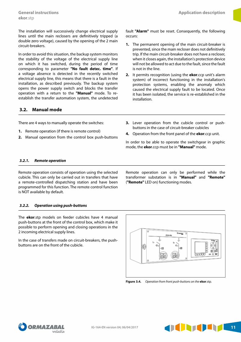
The ekor.stp models on feeder cubicles have 4 manual push-buttons at the front of the control box, which make it possible to perform opening and closing operations in the 2 incoming electrical supply lines.
In the case of transfers made on circuit-breakers, the push-buttons are on the front of the cubicle.
Figure 3.4. Operation from front push-buttons on the ekor.stp.
IG-164-EN version 04; 06/04/201712
Application description General instructionsekor.stp
The 2 incoming electrical supply lines can never be coupled under any circumstances. Hence, if an attempt is made to close one of the electrical supply line switches while the other is connected, the operation cannot be carried out. This interlock can be removed if specifically requested.
Operations from the control box push-buttons must only be carried out while the transformer substation is in "Manual" and "Local" mode ("Manual" and "Local" LEDs on). If they are carried out in "Automatic" mode, an alarm is triggered for exterior operation and the system switches to "Manual" mode.
3.2.3. Direct operation from the cubicle
cgmcosmos feeder cubicles permit manual operation using an actuating lever which is supplied with the equipment. The circuit-breaker cubicles allow the manual operation of the circuit-breaker using opening and closing push-buttons and of the disconnector using an actuating lever which is supplied with the equipment.
Figure 3.5. Push-buttons for opening and closing in circuit-breaker cubicles
This method of operation permits the coupling of both power supply lines. However, if this were to occur, the transformer substation would show an alarm situation without being able to switch to "Automatic" mode until the situation becomes normal again in the incoming electrical supply lines and the alarm generated has been reset.
The circuit-breaker cubicles have 2 push-buttons for local opening and closing.
3.2.4. Operation from the ekor.ccp unit
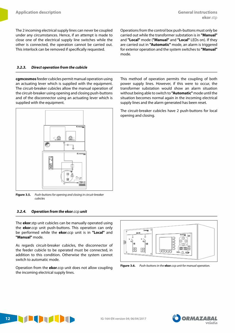
The ekor.stp unit cubicles can be manually operated using the ekor.ccp unit push-buttons. This operation can only be performed while the ekor.ccp unit is in "Local" and "Manual" mode.
As regards circuit-breaker cubicles, the disconnector of the feeder cubicle to be operated must be connected, in addition to this condition. Otherwise the system cannot switch to automatic mode.
Operation from the ekor.ccp unit does not allow coupling the incoming electrical supply lines.
Figure 3.6. Push-buttons in the ekor.ccp unit for manual operation.

IG-164-EN version 04; 06/04/2017 13
General instructionsekor.stp
Navigating the ekor.ccp menu
4. Navigating the ekor.ccp menu
This section enables familiarisation with the ekor.ccp programmable cubicle controller. A general introduction to the interface is presented, followed by a description
of the functions that the ekor.ccp brings to the ekor.stp automatic transfer unit.
4.1. Introduction to the ekor.ccp interface
When on standby, the display in the ekor.ccp unit remains switched off. To activate the display, press any of the buttons, accessing the general information screen.
1. General informationThe first screen shows the following information:
1 Substation name
2 Cubicle name
3 Cubicle indications
4 Cubicle driving mechanism status
5 Voltage indication
6 Preferred line indication
7 Switch error indication
8 Indication error
Figure 4.1. General information screen
This screen indicates the general status of the substation: status of the switches, absence/presence of voltage, tripping of protection relays, etc. Additionally, it is possible to access the remaining information on the installation using the display option selection keypad on this screen: alarms, statuses.
2. Selected cubicleOperations are carried out using the "Cubicle Screen", which is accessed from the main screen by pressing the "Selection" button. Once the cubicle's status is known, it can be operated by pressing the "Open" button or the "Close" button on the front of the ekor.ccp unit.
After choosing the operation to perform, the ekor.ccp unit requests that you confirm it, the options are "OK" or "Cancel".
Figure 4.2. Selected cubicle screen and operation confirmation
IG-164-EN version 04; 06/04/201714
Navigating the ekor.ccp menu General instructionsekor.stp
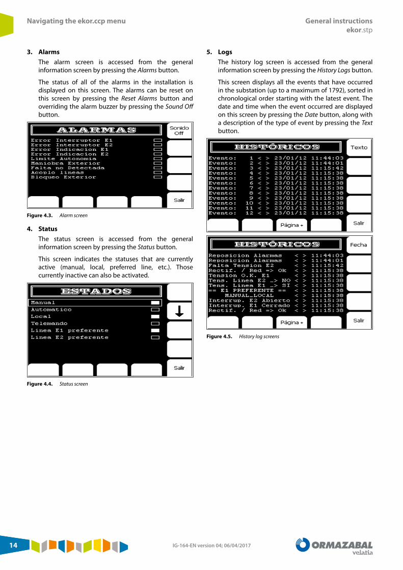
3. AlarmsThe alarm screen is accessed from the general information screen by pressing the Alarms button.
The status of all of the alarms in the installation is displayed on this screen. The alarms can be reset on this screen by pressing the Reset Alarms button and overriding the alarm buzzer by pressing the Sound Off button.
Figure 4.3. Alarm screen
4. StatusThe status screen is accessed from the general information screen by pressing the Status button.
This screen indicates the statuses that are currently active (manual, local, preferred line, etc.). Those currently inactive can also be activated.
Figure 4.4. Status screen
5. LogsThe history log screen is accessed from the general information screen by pressing the History Logs button.
This screen displays all the events that have occurred in the substation (up to a maximum of 1792), sorted in chronological order starting with the latest event. The date and time when the event occurred are displayed on this screen by pressing the Date button, along with a description of the type of event by pressing the Text button.
Figure 4.5. History log screens

IG-164-EN version 04; 06/04/2017 15
General instructionsekor.stp
Navigating the ekor.ccp menu
6. Inputs/OutputsThese screens display the status (active or inactive) of the physical inputs and outputs of the automaton. Active inputs/outputs (contact closed in the case of outputs) are displayed by a filled rectangle and inactive inputs/outputs by an empty one.
The input screen is accessed from the general information screen by pressing the I/O button. The output screen is accessed from the input screen by pressing the “Outputs” button.
Figure 4.6. Input and output screens

IG-164-EN version 04; 06/04/201716
Navigating the ekor.ccp menu General instructionsekor.stp
4.2. Menus system
The menus system is a tree with the following structure:
PARAMETERS
Change TIMES
No voltage timeReturn to normal voltageNo fault detec. timeDisplay off time
See No. OPERATIONS
E1 switching operationsE2 switching operations
TIME setSOFTWARE VERSION
4.3. Parameters
Parameters are displayed and adjusted using the "Menus Mode" and never the "Graphics Mode".
The parameters are always numerical. Place the cursor on the required parameter using the arrows .
To view the value of the parameter selected, press the "Enter" key. Once viewed, return to the parameter selection menu by clicking on "Cancel".
Parameter Default value Description
No voltage time 3 secondsTime needed without electrical voltage in one of the 2 power supply lines to start the automatic transfer operation
Return to normal voltage
3 minutesTime during which the volt-free line's electrical voltage remains uninterruptedly stable, this being the time needed for automatically returning to the transformer substation's initial configuration
Fault undetected time 10 secondsTime during which the transformer substation's supply is monitored. This monitoring is carried out after a supply switch has been closed, after the automatic line transfer
Display time off 1 minute Time that elapses until the ekor.ccp unit's screen goes into standby mode
E1 switching operations
Number of operations performed by the E1 cubicle switch
E2 switching operations
Number of operations performed by the E2 cubicle switch
Time Set Allows the user to adjust the day, month, year and local time
Table 4.1. Programmable parameters
In order to save modifications made to a parameter, you must press the "Enter" key after making them.
4.3.1. Date and time setting
To adjust the date and time, follow the steps below:
1. Starting from the main screen, choose the "Parameters" option using the keys and press "Enter" .
2. Choose "Time Set" and press "Enter".3. To make any modifications, move the '^' cursor through
the digits using the and keys.4. Change the settings value by pressing the key to take
1 unit away from the number, or the key to increase the number by 1 unit.
IG-164-EN version 04; 06/04/2017 17
General instructionsekor.stp
Navigating the ekor.ccp menu
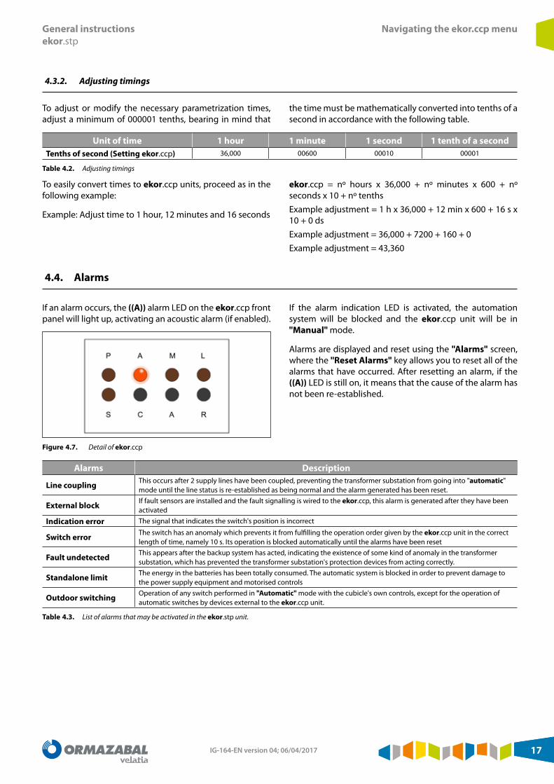
4.3.2. Adjusting timings
To adjust or modify the necessary parametrization times, adjust a minimum of 000001 tenths, bearing in mind that
the time must be mathematically converted into tenths of a second in accordance with the following table.
Unit of time 1 hour 1 minute 1 second 1 tenth of a secondTenths of second (Setting ekor.ccp) 36,000 00600 00010 00001
Table 4.2. Adjusting timings
To easily convert times to ekor.ccp units, proceed as in the following example:
Example: Adjust time to 1 hour, 12 minutes and 16 seconds
ekor.ccp = nº hours x 36,000 + nº minutes x 600 + nº seconds x 10 + nº tenthsExample adjustment = 1 h x 36,000 + 12 min x 600 + 16 s x 10 + 0 dsExample adjustment = 36,000 + 7200 + 160 + 0Example adjustment = 43,360
4.4. Alarms
If an alarm occurs, the ((A)) alarm LED on the ekor.ccp front panel will light up, activating an acoustic alarm (if enabled).
Figure 4.7. Detail of ekor.ccp
If the alarm indication LED is activated, the automation system will be blocked and the ekor.ccp unit will be in "Manual" mode.
Alarms are displayed and reset using the "Alarms" screen, where the "Reset Alarms" key allows you to reset all of the alarms that have occurred. After resetting an alarm, if the ((A)) LED is still on, it means that the cause of the alarm has not been re-established.
Alarms Description
Line coupling This occurs after 2 supply lines have been coupled, preventing the transformer substation from going into "automatic" mode until the line status is re-established as being normal and the alarm generated has been reset.
External block If fault sensors are installed and the fault signalling is wired to the ekor.ccp, this alarm is generated after they have been activated
Indication error The signal that indicates the switch's position is incorrect
Switch error The switch has an anomaly which prevents it from fulfilling the operation order given by the ekor.ccp unit in the correct length of time, namely 10 s. Its operation is blocked automatically until the alarms have been reset
Fault undetected This appears after the backup system has acted, indicating the existence of some kind of anomaly in the transformer substation, which has prevented the transformer substation's protection devices from acting correctly.
Standalone limit The energy in the batteries has been totally consumed. The automatic system is blocked in order to prevent damage to the power supply equipment and motorised controls
Outdoor switching Operation of any switch performed in "Automatic" mode with the cubicle's own controls, except for the operation of automatic switches by devices external to the ekor.ccp unit.
Table 4.3. List of alarms that may be activated in the ekor.stp unit.

IG-164-EN version 04; 06/04/201718
Navigating the ekor.ccp menu General instructionsekor.stp
4.5. Definition of events log texts
The history log texts and their descriptions are as follows:
History log text Description== E1 preferred == Line E1 has been selected as the "PREFERRED" line
== E2 preferred == Line E2 has been selected as the "PREFERRED" line
=== Connection ekor.ccp ===
The ekor.ccp cubicle controller has been connected to the auxiliary voltage.
Automatic Automation in "Automatic" mode
Automation block Transfer automation is blocked
Ext. block enabled The external blocking signal has been activated and therefore the system is forced into "Manual" mode, blocking the automation system
Ext. block disabled The external blocking signal has been disabled
Fault undetected After cutting off a power supply, electrical voltage has been lost during the monitoring period "Fault undetected”
No voltage E1 No electrical voltage in the 3 phases of the E1 supply feeder cubicle for time "No voltage time".
No voltage E2 No electrical voltage in the 3 phases of the E2 supply feeder cubicle for time "No voltage time".
Charger Fault -> NO The self-powered equipment's charger does not detect any errors
Charger Fault -> YES The self-powered equipment's charger has detected an error and switches the automation system into "Manual" mode
Rectif. fault/NETWORK The self-powered equipment's AC power supply has been interrupted or there is a fault in the rectifier
E1 error indication Error in the E1 cubicle's switch status indication
E2 error indication Error in the E2 cubicle's switch status indication
E1 Switch error E1 cubicle switch operation error
E2 Switch error E2 cubicle switch operation error
E1 Switch open The E1 cubicle's switch has changed to open position
E1 Switch closed The E1 cubicle's switch has changed to closed position
E2 Switch open The E2 cubicle's switch has changed to open position
E2 Switch closed The E2 cubicle's switch has changed to closed position
Standalone limit The energy in the batteries has been totally consumed. The automatic system is blocked in order to prevent damage to the power supply equipment and motorised controls
E1 Outdoor switching E1 cubicle switch operation not performed from the controller in automatic mode
E2 Outdoor switching E2 cubicle switch operation not performed from the controller in automatic mode
Manual-local Automation system set to "Manual-local" mode
Manual-tele Automation system remotely switched from "Automatic" mode to "Manual" mode by means of remote control
RECTIF./NETWORK => OK The self-powered equipment's AC power supply has been re-established or a fault in the rectifier has been corrected
Alarms reset The "Alarms reset" option has been selected in the controller
E1 feeder voltage → NO Electrical voltage has been lost in one of the 3 phases of the E1 power supply feeder cubicle
E2 feeder voltage → NO Electrical voltage has been lost in one of the 3 phases of the E2 power supply feeder cubicle
E1 feeder voltage → YES The electrical voltage has been recovered in all of the phases of the E1 power supply line
E2 feeder voltage → YES The electrical voltage has been recovered in all of the phases of the E2 power supply line
Voltage OK E1 All of the E1 power supply line phases have recovered electrical voltage, which has remained stable for time "Return to normal volt»
Voltage OK E2 All of the E2 power supply phases have recovered electrical voltage, which has remained stable for time "Return to Normal".
Table 4.4. List of events log texts

IG-164-EN version 04; 06/04/2017 19
General instructionsekor.stp
Commissioning instructions
5. Commissioning instructions
5.1. Control equipment power supply
To feed to the control equipment, proceed as follows:
1. Check that all of the power supply and control equipment's miniature circuit-breakers and fuses are open.
2. Reach 230 Vac for feeding the control box using a sheath with 3 conductors or 3 separate connection cables with a 1.5 mm2 cross-section.
3. Connect the AC power supply to the corresponding terminals, following the self-powered equipment user manual (if it is not integrated into the control system). If the ekor.stp has integrated self-powered equipment, connect the power supply cables to the terminals labelled "230", "0" and "^".
5.1.1. Activating the equipment
To activate the equipment, proceed as follows:
1. Close the miniature circuit-breaker identified as "CP" for activating ekor.ccp, which must show its status by the LEDs "Auxiliary", "Local", "Manual" being on and "Service" flashing.
2. Press any ekor.ccp key to switch on the display, thus activating "Graphic mode".
3. Close the miniature circuit-breakers "L1" and "L2", corresponding to the power supplies of the feeder cubicles L1 and L2, respectively.
5.1.2. Precautions during commissioning
It is recommended that you connect the self-powered equipment 24 hours before commissioning the installation. To do this, feed it with an AC current, keeping the miniature circuit-breakers identified as "CP", "L1" and "L2" open until the battery is charged to the correct level.
In terms of the feeder cubicle's operability, the following should be taken into consideration:
1. When switching from "Manual" to "Automatic" mode, automatic operations can be performed if any of the conditions described in section 5 of this document, "Description of the application of the programmable transfer system (ekor.stp)” are met.
2. If the switch in the feeder cubicle is in earthing position, its operation cannot be motorised.
5.2. Checking information on the main screen
5.2.1. Presence of electrical voltage
Correspondence between the feeder cubicles and the ekor.ccp must be checked in accordance with the following table:
Cubicle E1 Cubicle E2
Voltage presence indication lights
Display indication ekor.ccp
Voltage presence indication lights
Display indication ekor.ccp
All 3 light up (presence) Filled circle All 3 light up (presence) Filled circleNo lights are on (absence) Empty circle No lights are on (absence) Empty circle
Table 5.1. Correspondence between the feeder cubicles and the ekor.ccp

IG-164-EN version 04; 06/04/201720
Commissioning instructions General instructionsekor.stp
While the ekor.rtk or the ekor.rpg.ci is fed and with no electrical voltage in the electrical supply line, ekor.ccp shows the absence of voltage on screen.
1 Voltage presence graphic indication
Figure 5.1. Correspondence between the feeder cubicles and the ekor.ccp
5.2.2. Voltage presence simulation
With ekor.rtk
To simulate the presence of voltage, press the test button on the side of the ekor.rtk while pressing the test button, ekor.ccp shows the presence of voltage on screen (both in menu mode and in graphic mode). Stopping pressing the test button, ekor.ccp, shows absence of voltage.
This test button changes the status of the output contacts of the ekor.rtk.
1 Test push-button
Figure 5.2. Voltage presence simulation
With ekor.rpg.ci
To simulate the presence of voltage, disconnect the output cable of the ekor.rpg.ci corresponding to "Voltage presence". To simulate the presence of voltage, apply a positive impulse to the terminal of terminal block A corresponding to the "Voltage presence" output. Voltage presence/absence signalling in the ekor.ccp is modified by applying a positive impulse to the terminal or disconnecting the cable. See the project diagrams to confirm which ekor.rpg.ci output to use for this signalling.
IG-164-EN version 04; 06/04/2017 21
General instructionsekor.stp
Commissioning instructions
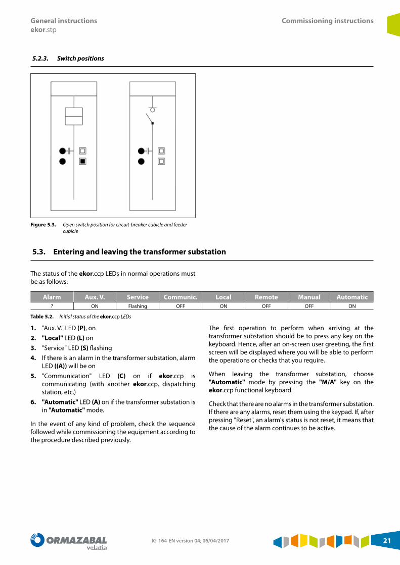
5.2.3. Switch positions
Figure 5.3. Open switch position for circuit-breaker cubicle and feeder cubicle
5.3. Entering and leaving the transformer substation
The status of the ekor.ccp LEDs in normal operations must be as follows:
Alarm Aux. V. Service Communic. Local Remote Manual Automatic? ON Flashing OFF ON OFF OFF ON
Table 5.2. Initial status of the ekor.ccp LEDs
1. "Aux. V." LED (P), on2. "Local" LED (L) on3. "Service" LED (S) flashing4. If there is an alarm in the transformer substation, alarm
LED ((A)) will be on5. "Communication" LED (C) on if ekor.ccp is
communicating (with another ekor.ccp, dispatching station, etc.)
6. "Automatic" LED (A) on if the transformer substation is in "Automatic" mode.
In the event of any kind of problem, check the sequence followed while commissioning the equipment according to the procedure described previously.
The first operation to perform when arriving at the transformer substation should be to press any key on the keyboard. Hence, after an on-screen user greeting, the first screen will be displayed where you will be able to perform the operations or checks that you require.
When leaving the transformer substation, choose "Automatic" mode by pressing the "M/A" key on the ekor.ccp functional keyboard.
Check that there are no alarms in the transformer substation. If there are any alarms, reset them using the keypad. If, after pressing "Reset", an alarm's status is not reset, it means that the cause of the alarm continues to be active.
IG-164-EN version 04; 06/04/201722
Anomalies General instructionsekor.stp
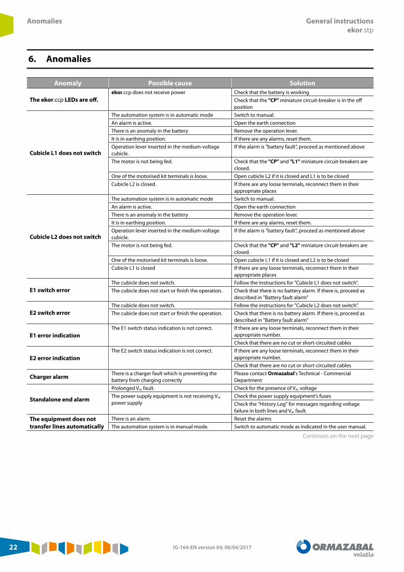
6. Anomalies
Anomaly Possible cause Solution
The ekor.ccp LEDs are off.ekor.ccp does not receive power Check that the battery is working
Check that the "CP" miniature circuit-breaker is in the off position
Cubicle L1 does not switch
The automation system is in automatic mode Switch to manual.An alarm is active. Open the earth connectionThere is an anomaly in the battery Remove the operation lever.It is in earthing position. If there are any alarms, reset them.Operation lever inserted in the medium-voltage cubicle.
If the alarm is "battery fault”, proceed as mentioned above
The motor is not being fed. Check that the "CP" and "L1" miniature circuit-breakers are closed.
One of the motorised kit terminals is loose. Open cubicle L2 if it is closed and L1 is to be closedCubicle L2 is closed. If there are any loose terminals, reconnect them in their
appropriate places
Cubicle L2 does not switch
The automation system is in automatic mode Switch to manual.An alarm is active. Open the earth connectionThere is an anomaly in the battery Remove the operation lever.It is in earthing position. If there are any alarms, reset them.Operation lever inserted in the medium-voltage cubicle.
If the alarm is "battery fault”, proceed as mentioned above
The motor is not being fed. Check that the "CP" and "L2" miniature circuit-breakers are closed.
One of the motorised kit terminals is loose. Open cubicle L1 if it is closed and L2 is to be closedCubicle L1 is closed If there are any loose terminals, reconnect them in their
appropriate places
E1 switch errorThe cubicle does not switch. Follow the instructions for "Cubicle L1 does not switch".The cubicle does not start or finish the operation. Check that there is no battery alarm. If there is, proceed as
described in "Battery fault alarm”
E2 switch errorThe cubicle does not switch. Follow the instructions for "Cubicle L2 does not switch".The cubicle does not start or finish the operation. Check that there is no battery alarm. If there is, proceed as
described in "Battery fault alarm"
E1 error indicationThe E1 switch status indication is not correct. If there are any loose terminals, reconnect them in their
appropriate number.Check that there are no cut or short-circuited cables
E2 error indicationThe E2 switch status indication is not correct. If there are any loose terminals, reconnect them in their
appropriate number.Check that there are no cut or short-circuited cables
Charger alarm There is a charger fault which is preventing the battery from charging correctly
Please contact Ormazabal's Technical - Commercial Department
Standalone end alarm
Prolonged Vac fault. Check for the presence of Vac voltageThe power supply equipment is not receiving Vac power supply
Check the power supply equipment's fusesCheck the "History Log" for messages regarding voltage failure in both lines and Vac fault.
The equipment does not transfer lines automatically
There is an alarm. Reset the alarmsThe automation system is in manual mode. Switch to automatic mode as indicated in the user manual.
Continues on the next page
IG-164-EN version 04; 06/04/2017 23
General instructionsekor.stp
Anomalies
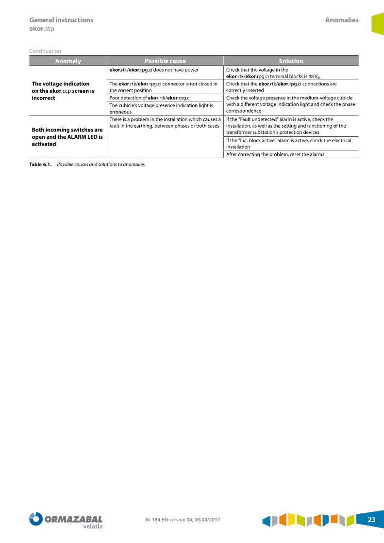
Continuation
Anomaly Possible cause Solution
The voltage indication on the ekor.ccp screen is incorrect
ekor.rtk/ekor.rpg.ci does not have power Check that the voltage in the ekor.rtk/ekor.rpg.ci terminal blocks is 48 Vdc
The ekor.rtk/ekor.rpg.ci connector is not closed in the correct position
Check that the ekor.rtk/ekor.rpg.ci connections are correctly inserted
Poor detection of ekor.rtk/ekor.rpg.ci Check the voltage presence in the medium-voltage cubicle with a different voltage indication light and check the phase correspondence
The cubicle's voltage presence indication light is erroneous
Both incoming switches are open and the ALARM LED is activated
There is a problem in the installation which causes a fault in the earthing, between phases or both cases
If the "Fault undetected" alarm is active, check the installation, as well as the setting and functioning of the transformer substation's protection devices
If the "Ext. block active" alarm is active, check the electrical installationAfter correcting the problem, reset the alarms
Table 6.1. Possible causes and solutions to anomalies

IG-164-EN version 04; 06/04/201724
Associated documentation General instructionsekor.stp
7. Associated documentation
The following documentation references correspond to the General Instructions documents of the various models of units mentioned in this document:
1. IG-094: ekor.rtk Voltage detection unit2. IG-156: ekor.ccp Programmable cubicle controller3. IG-157: ekor.rpg.ci Protection unit
4. ekor.ccp-evt Software: Ormazabal's IG-156 document describes how this software works
5. If there is no advanced automation or non-standard topology, this IG will have a specific annex for the particular project with specific descriptions of the automation, in addition to necessary guidelines on verification and commissioning.

General instructionsekor.stp
Notes
Notes
IG-164-EN version 04; 06/04/2017 25

Notes General instructionsekor.stp
Notes
IG-164-EN version 04; 06/04/201726
General instructionsekor.stp
Notes
Notes
IG-164-EN version 04; 06/04/2017 27

Subject to change without prior notice.
For further information, contact Ormazabal.
Ormazabal Protection & Automation
IGORRE Spain
www.ormazabal.com