EITF35: Introduction to Structured VLSI Design · Lund University / EITF35/ Liang Liu ASM...
36
Lund University / EITF35/ Liang Liu EITF35: Introduction to Structured VLSI Design Part 3.1.1: FSMD Liang Liu [email protected] 1
Transcript of EITF35: Introduction to Structured VLSI Design · Lund University / EITF35/ Liang Liu ASM...
Lund University / EITF35/ Liang Liu
EITF35: Introduction to Structured
VLSI Design
Part 3.1.1: FSMD
Liang Liu
1
Lund University / EITF35/ Liang Liu
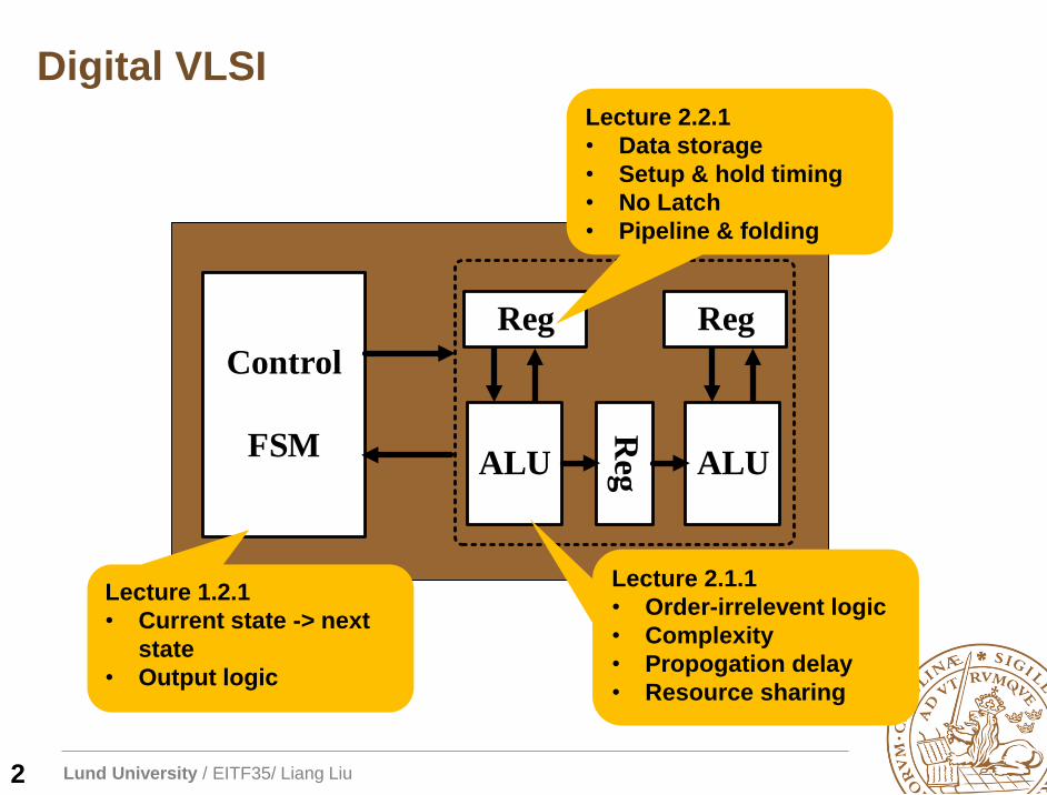
Digital VLSI
2
Control
FSMR
egALU ALU
Reg Reg
Lecture 1.2.1
• Current state -> next
state
• Output logic
Lecture 2.1.1
• Order-irrelevent logic
• Complexity
• Propogation delay
• Resource sharing
Lecture 2.2.1
• Data storage
• Setup & hold timing
• No Latch
• Pipeline & folding
Lund University / EITF35/ Liang Liu
Outline
FSMD Overview
Algorithmic state machine with data-path (ASMD)
FSMD design of a repetitive-addition multiplier
3
Lund University / EITF35/ Liang Liu
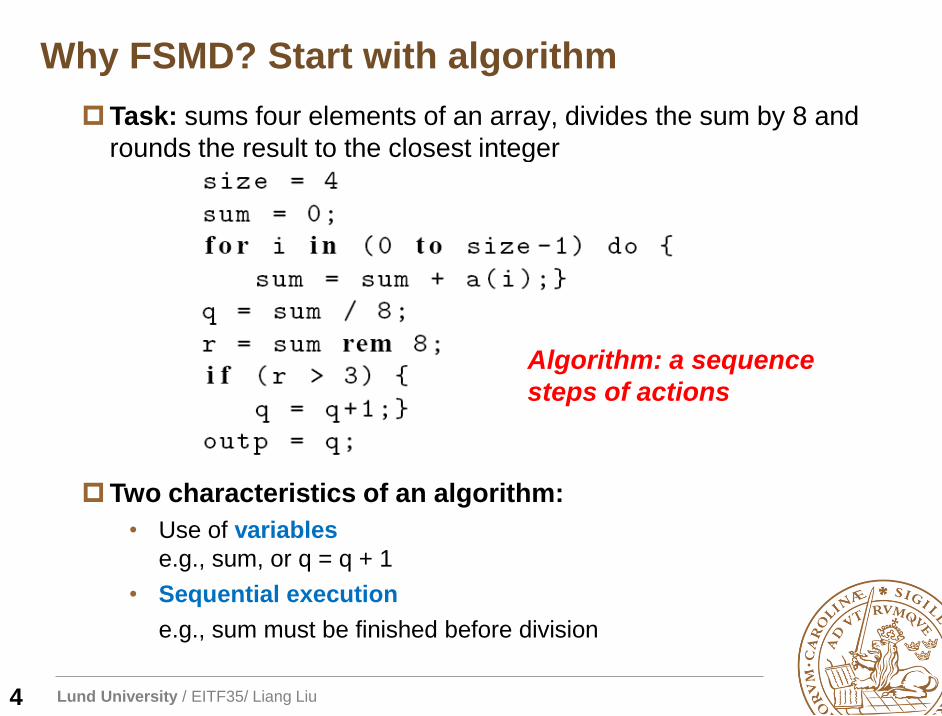
Why FSMD? Start with algorithm
Task: sums four elements of an array, divides the sum by 8 and
rounds the result to the closest integer
Two characteristics of an algorithm:
• Use of variables
e.g., sum, or q = q + 1
• Sequential execution
e.g., sum must be finished before division
Algorithm: a sequence
steps of actions
4
Lund University / EITF35/ Liang Liu
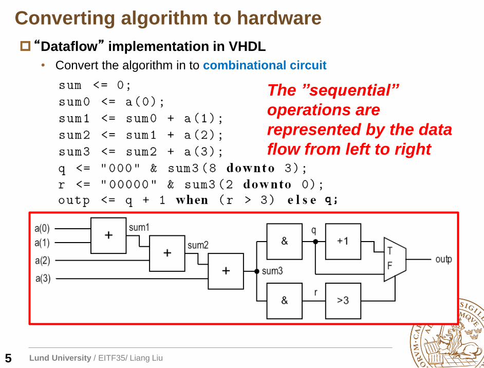
“Dataflow” implementation in VHDL
• Convert the algorithm in to combinational circuit
Converting algorithm to hardware
5
The ”sequential”
operations are
represented by the data
flow from left to right
Lund University / EITF35/ Liang Liu
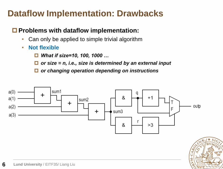
Problems with dataflow implementation:
• Can only be applied to simple trivial algorithm
• Not flexible
What if size=10, 100, 1000 …
or size = n, i.e., size is determined by an external input
or changing operation depending on instructions
Dataflow Implementation: Drawbacks
6
Lund University / EITF35/ Liang Liu
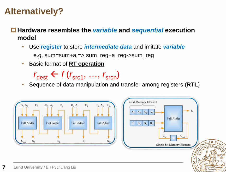
Alternatively?
Hardware resembles the variable and sequential execution
model
• Use register to store intermediate data and imitate variable
e.g. sum=sum+a => sum_reg+a_reg->sum_reg
• Basic format of RT operation
rdest f (rsrc1, …, rsrcn)• Sequence of data manipulation and transfer among registers (RTL)
7
Lund University / EITF35/ Liang Liu
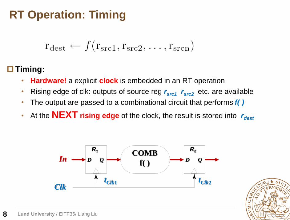
RT Operation: Timing
Timing:
• Hardware! a explicit clock is embedded in an RT operation
• Rising edge of clk: outputs of source reg rsrc1 rsrc2 etc. are available
• The output are passed to a combinational circuit that performs f( )
• At the NEXT rising edge of the clock, the result is stored into rdest
8
R1
D QCOMB
f( )In
ClktClk1
R2
D Q
tClk2
Lund University / EITF35/ Liang Liu
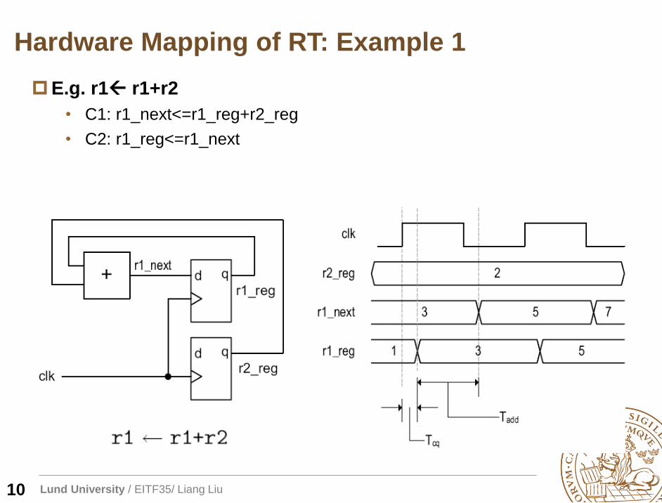
Hardware Mapping of RT: Example 1
E.g. r1 r1+r2
• C1: r1_next<=r1_reg+r2_reg
• C2: r1_reg<=r1_next
10
Lund University / EITF35/ Liang Liu
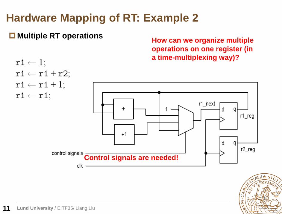
Multiple RT operationsHow can we organize multiple
operations on one register (in
a time-multiplexing way)?
Hardware Mapping of RT: Example 2
Control signals are needed!
11
Lund University / EITF35/ Liang Liu
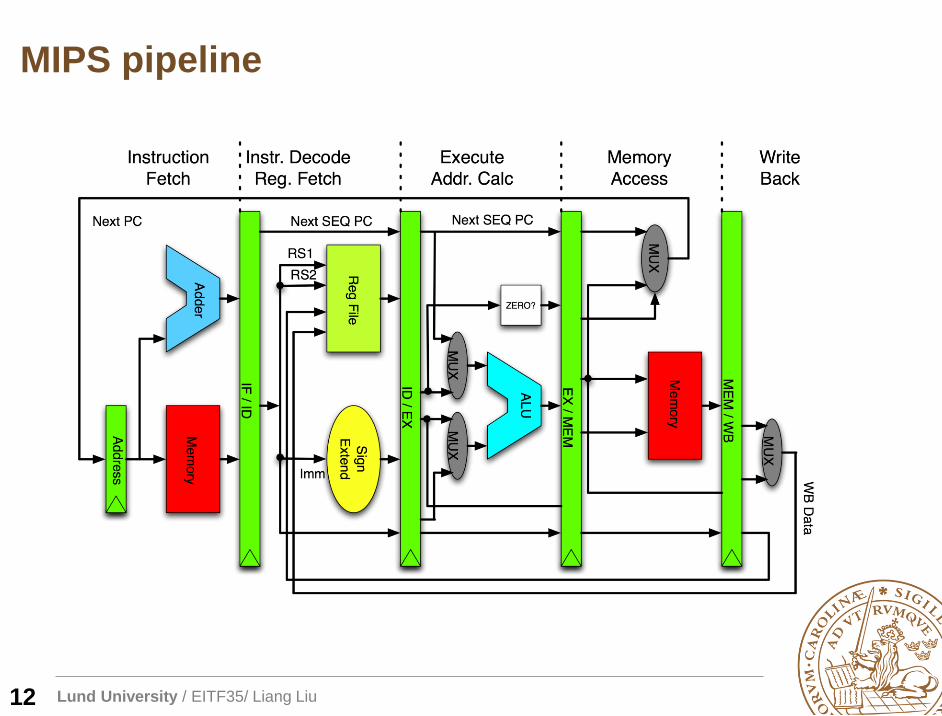
MIPS pipeline
12
Lund University / EITF35/ Liang Liu
FSM as Control Path
FSMD: FSM with data path
• Use a data path to realize all the
required RT operations
• Use a control path (FSM) to
specify the order of RT operation
13
Lund University / EITF35/ Liang Liu
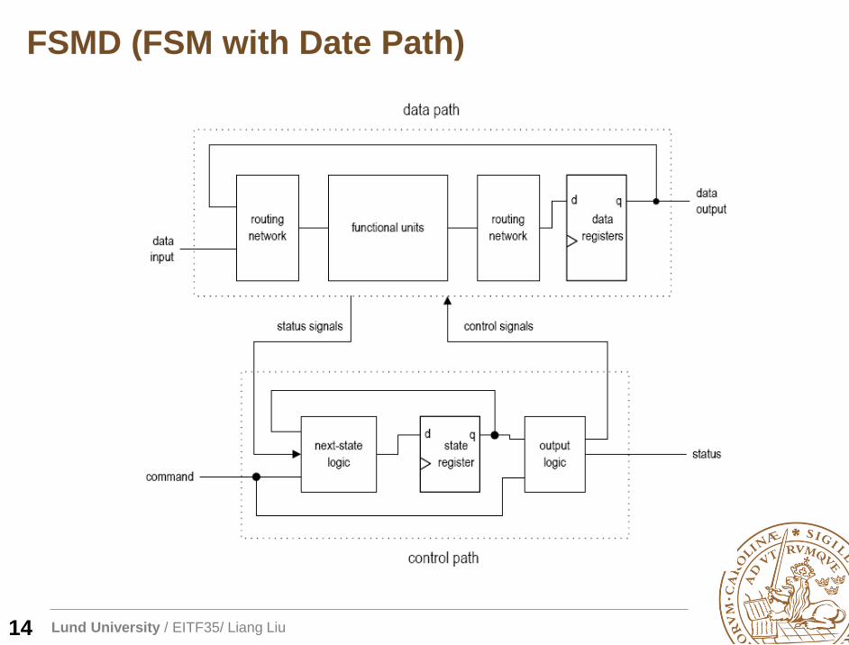
FSMD (FSM with Date Path)
14
Lund University / EITF35/ Liang Liu
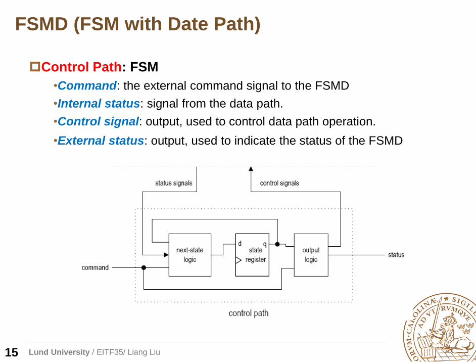
FSMD (FSM with Date Path)
Control Path: FSM
•Command: the external command signal to the FSMD
•Internal status: signal from the data path.
•Control signal: output, used to control data path operation.
•External status: output, used to indicate the status of the FSMD
15
Lund University / EITF35/ Liang Liu
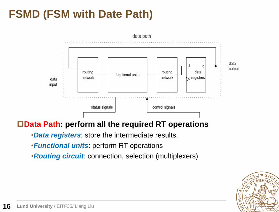
FSMD (FSM with Date Path)
Data Path: perform all the required RT operations
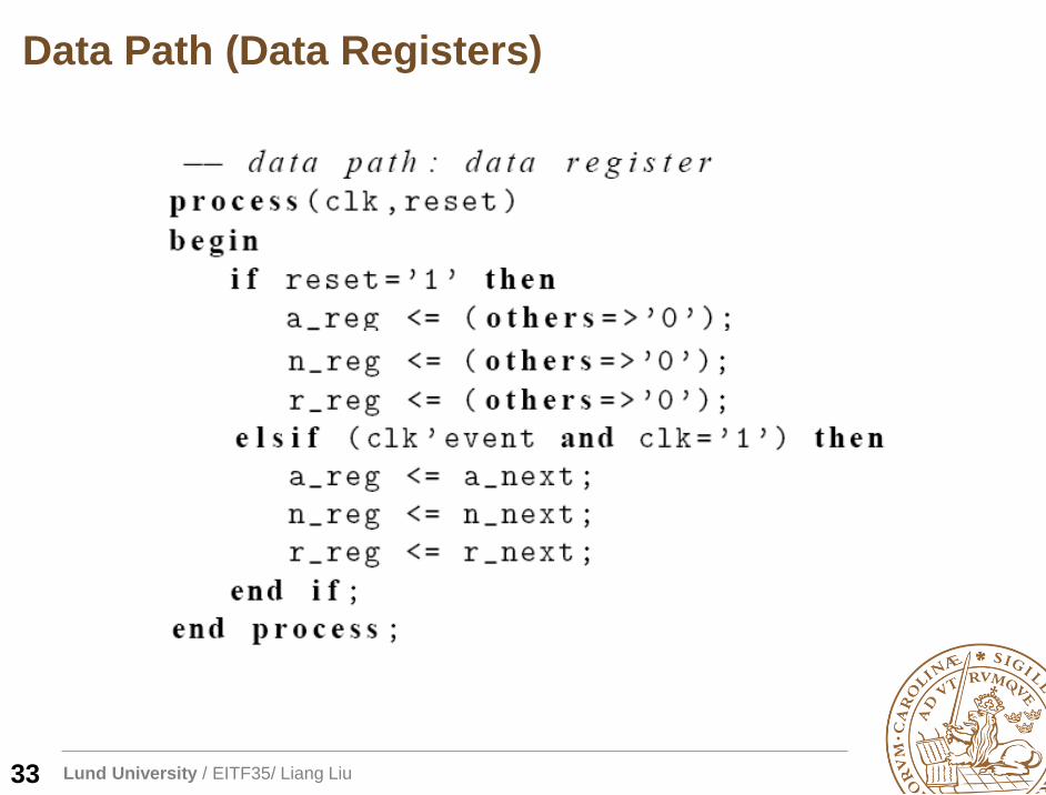
•Data registers: store the intermediate results.
•Functional units: perform RT operations
•Routing circuit: connection, selection (multiplexers)
16
Lund University / EITF35/ Liang Liu
Outline
Overview of FSMD
Algorithmic state machine with data-path (ASMD)
FSMD design of a repetitive-addition multiplier
Timing analysis of FSMD
17
Lund University / EITF35/ Liang Liu
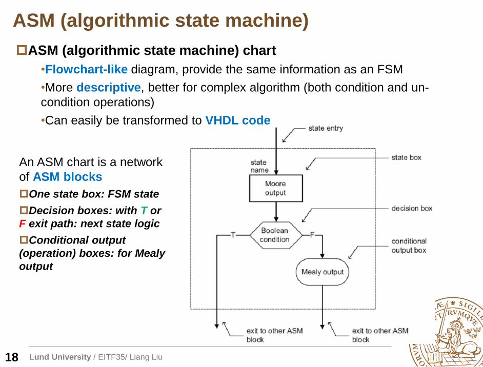
ASM (algorithmic state machine) chart
•Flowchart-like diagram, provide the same information as an FSM
•More descriptive, better for complex algorithm (both condition and un-
condition operations)
•Can easily be transformed to VHDL code
ASM (algorithmic state machine)
An ASM chart is a network
of ASM blocks
One state box: FSM state
Decision boxes: with T or
F exit path: next state logic
Conditional output
(operation) boxes: for Mealy
output
18
Lund University / EITF35/ Liang Liu
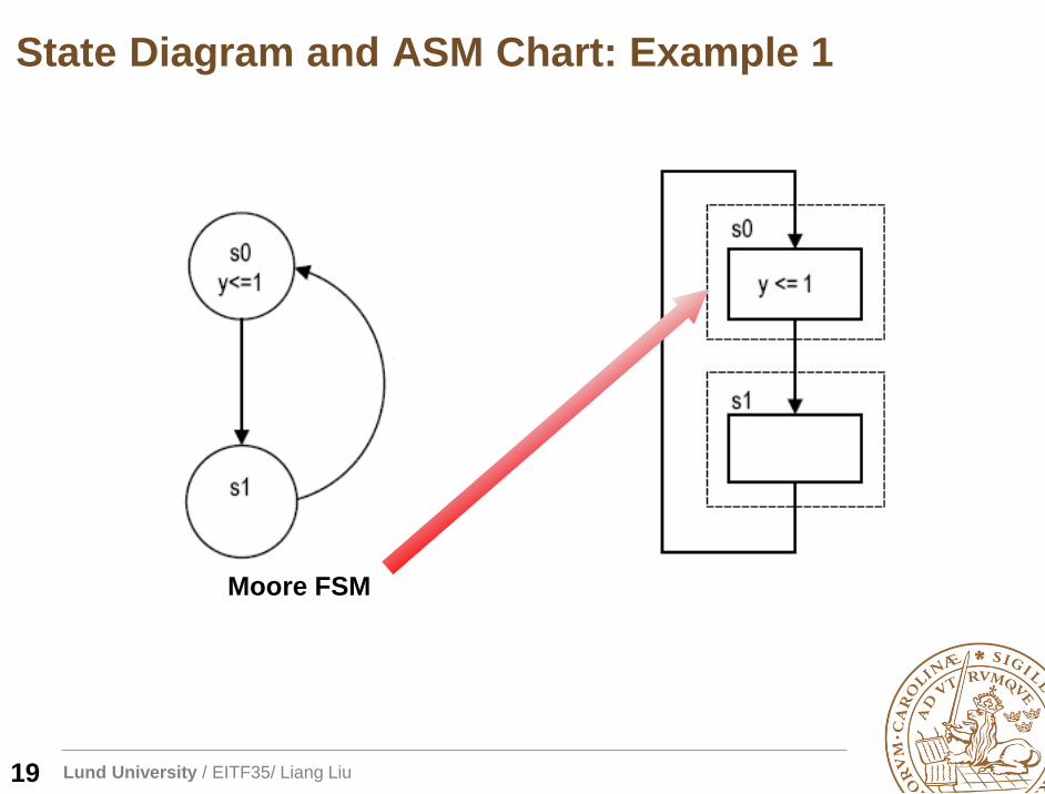
State Diagram and ASM Chart: Example 1
Moore FSM
19
Lund University / EITF35/ Liang Liu
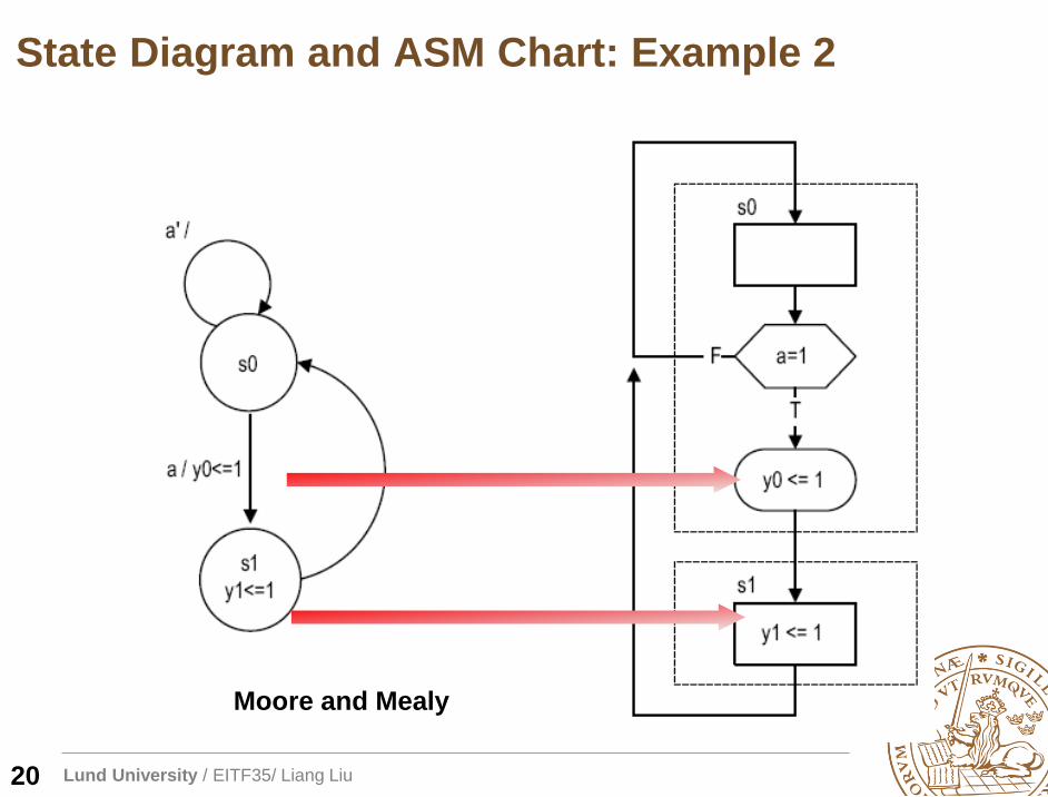
Moore and Mealy
State Diagram and ASM Chart: Example 2
20
Lund University / EITF35/ Liang Liu
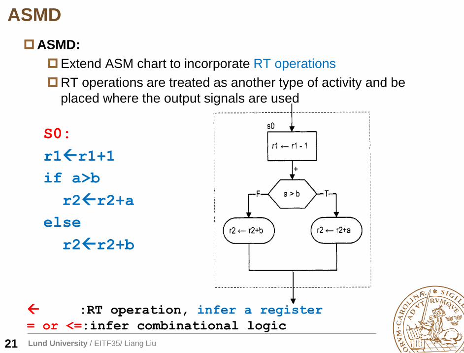
ASMD
21
ASMD:
Extend ASM chart to incorporate RT operations
RT operations are treated as another type of activity and be
placed where the output signals are used
S0:
r1r1+1
if a>b
r2r2+a
else
r2r2+b
+
:RT operation, infer a register
= or <=:infer combinational logic
Lund University / EITF35/ Liang Liu
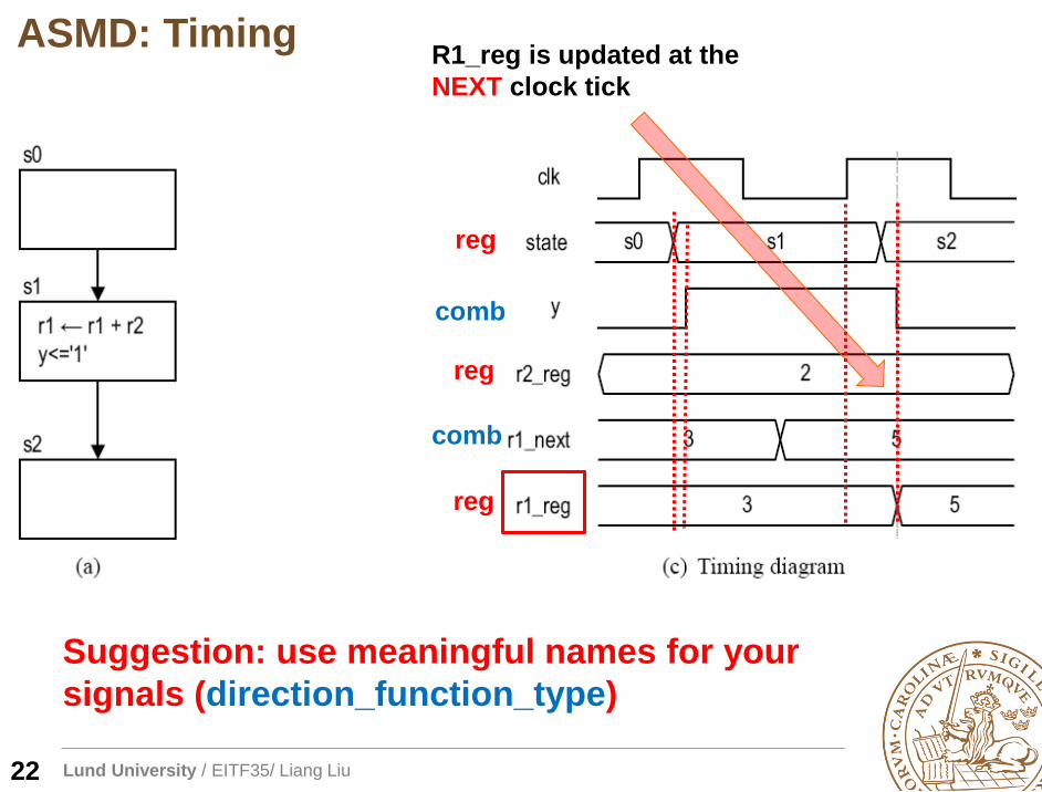
Suggestion: use meaningful names for your
signals (direction_function_type)
ASMD: TimingR1_reg is updated at the
NEXT clock tick
22
reg
reg
reg
comb
comb
Lund University / EITF35/ Liang Liu
Outline
Overview of FSMD
Algorithmic state machine with data-path (ASMD)
FSMD design of a repetitive-addition multiplier
Timing analysis of FSMD
23
Lund University / EITF35/ Liang Liu
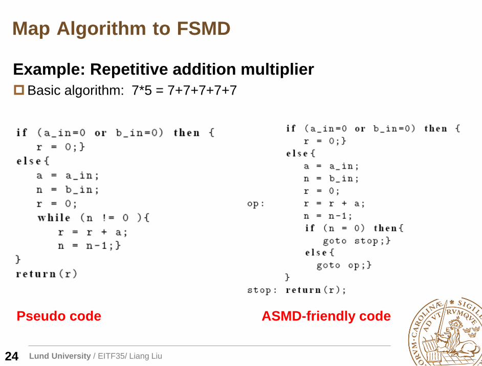
Map Algorithm to FSMD
Example: Repetitive addition multiplier
Basic algorithm: 7*5 = 7+7+7+7+7
Pseudo code ASMD-friendly code
24
Lund University / EITF35/ Liang Liu
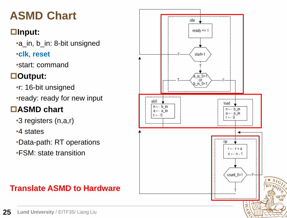
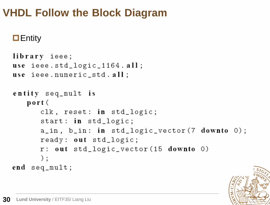
Input:
•a_in, b_in: 8-bit unsigned
•clk, reset
•start: command
Output:
•r: 16-bit unsigned
•ready: ready for new input
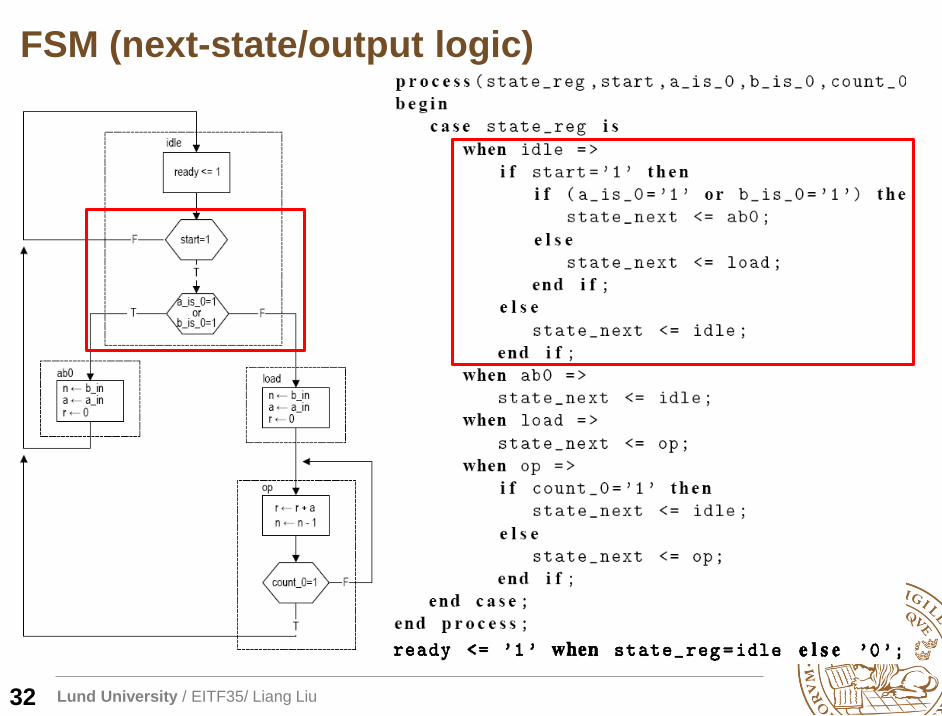
ASMD chart
•3 registers (n,a,r)
•4 states
•Data-path: RT operations
•FSM: state transition
ASMD Chart
25
Translate ASMD to Hardware
Lund University / EITF35/ Liang Liu
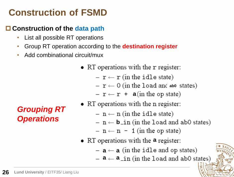
Construction of the data path
• List all possible RT operations
• Group RT operation according to the destination register
• Add combinational circuit/mux
Construction of FSMD
26
a
b
ab0
Grouping RT
Operations
a
a
a
a
a
Lund University / EITF35/ Liang Liu
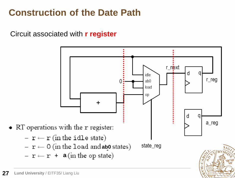
Circuit associated with r register
ab0
a
Construction of the Date Path
27
Lund University / EITF35/ Liang Liu
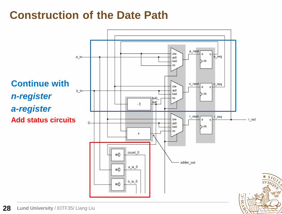
Continue with
n-register
a-register
Add status circuits
28
Construction of the Date Path
Lund University / EITF35/ Liang Liu
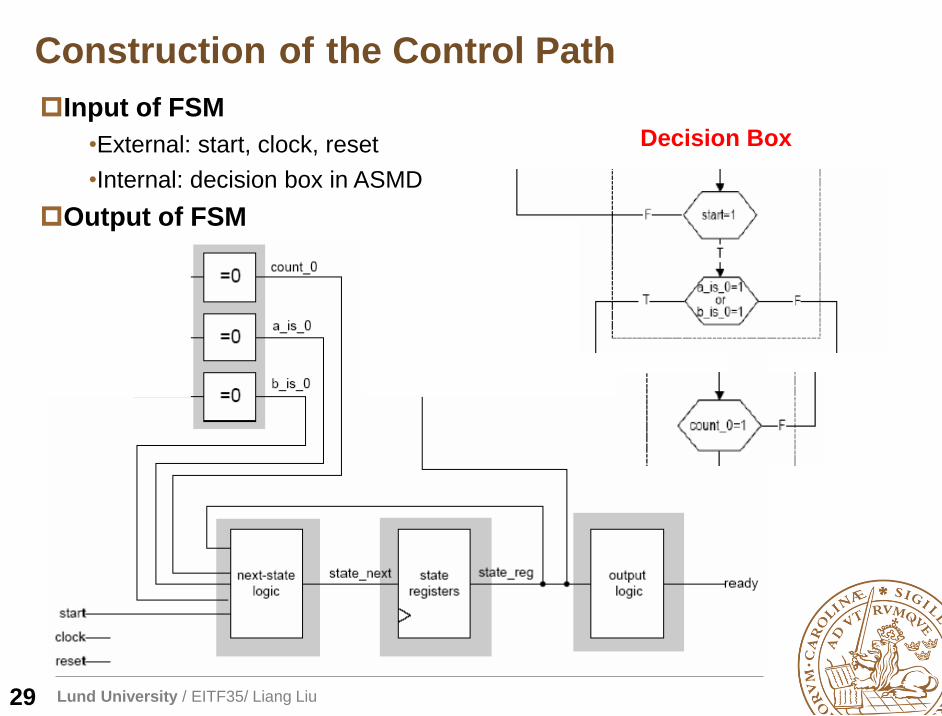
Input of FSM
•External: start, clock, reset
•Internal: decision box in ASMD
Output of FSM
Construction of the Control Path
29
Decision Box
Lund University / EITF35/ Liang Liu
Entity
VHDL Follow the Block Diagram
30
Lund University / EITF35/ Liang Liu
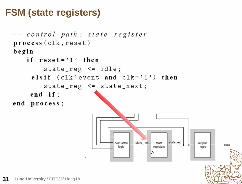
FSM (state registers)
31
Lund University / EITF35/ Liang Liu
FSM (next-state/output logic)
32
Lund University / EITF35/ Liang Liu
Data Path (Data Registers)
33
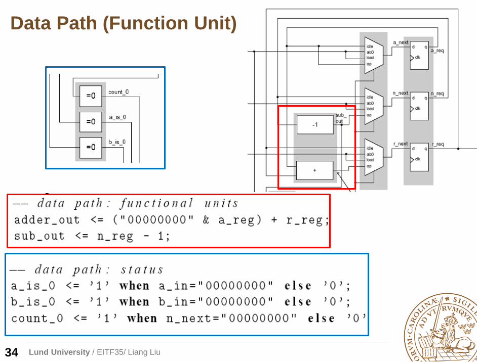
Lund University / EITF35/ Liang Liu
Data Path (Function Unit)
34
Lund University / EITF35/ Liang Liu
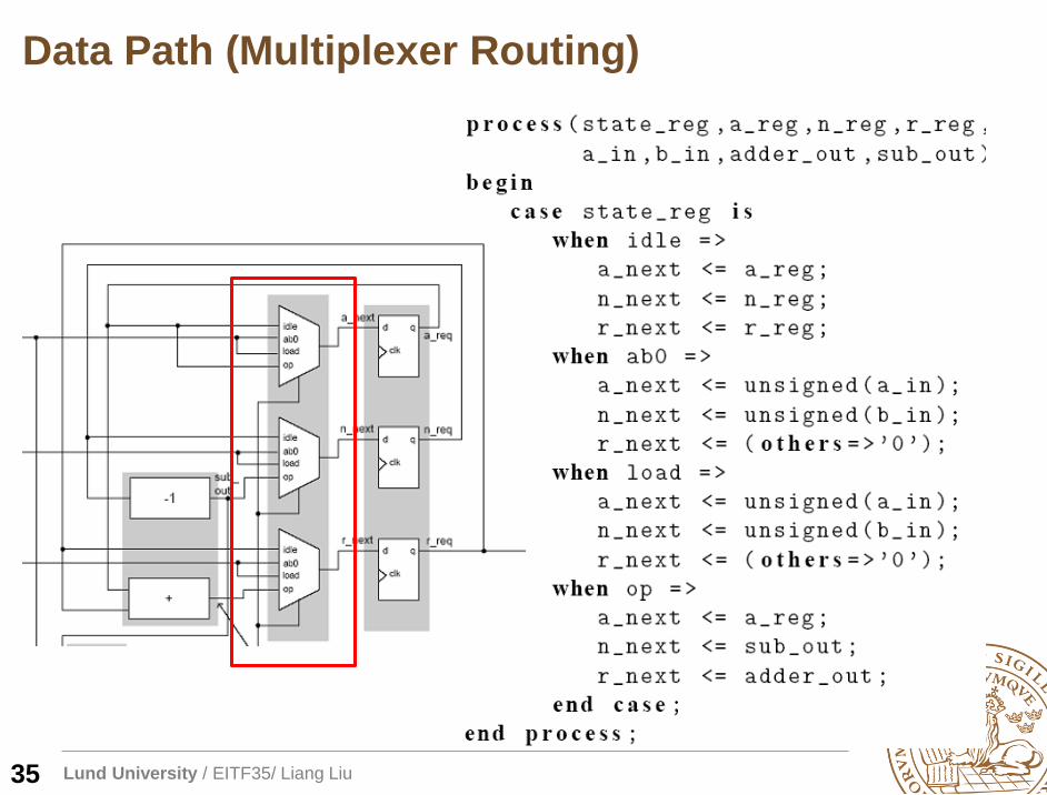
Data Path (Multiplexer Routing)
35
Lund University / EITF35/ Liang Liu
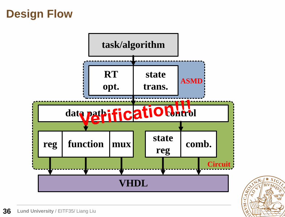
Design Flow
36
task/algorithm
RT
opt.
state
trans.
data path control
reg function muxstate
regcomb.
VHDL
ASMD
Circuit
Lund University / EITF35/ Liang Liu
Thanks!